
IAN 295607 - Balance bike Playtive - Free user manual and instructions
Find the device manual for free IAN 295607 Playtive in PDF.
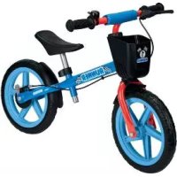
| Product type | Balance bike for children |
| Brand | Playtive |
| Model | IAN 295607 |
| Recommended age | 2 to 5 years |
| Child's height | 85 to 120 cm |
| Maximum user weight | 50 kg |
| Bike weight (with accessories) | Approximately 3.8 kg |
| Adjustable saddle height | 32 to 43 cm |
| Dimensions (H x L x W) | 52 x 82 x 44 cm |
| Frame material | Steel |
| Wheels | Rubber, with bearings |
| Brake | Rear hand brake (optional, supplied disassembled) |
| Adjustable steering limiter | 23° or 33° |
| Included accessories | Basket, bell, impact protection, front and rear mudguards, decals |
| Usage | Private, do not use on public roads |
| Maintenance | Clean with water, oil every 3 months |
| Warranty | 3 years |
| Customer service France | 0800 919270 |
| Customer service Belgium | 070 270 171 (€0.15/min) |
Frequently Asked Questions - IAN 295607 Playtive
User questions about IAN 295607 Playtive
0 question about this device. Answer the ones you know or ask your own.
Ask a new question about this device
Download the instructions for your Balance bike in PDF format for free! Find your manual IAN 295607 - Playtive and take your electronic device back in hand. On this page are published all the documents necessary for the use of your device. IAN 295607 by Playtive.
USER MANUAL IAN 295607 Playtive
Assembly instructions
① ME
LOOPFIEIS
op
BALANCE BIKE
Before reading, fold out the illustration page and get to know all of the functions of your unit.
Fig. 11
GS/IE Instructions and Safety Notice Page 16

DE AT CH
Scope of delivery 12
Technical data 12
Risk of injury! 16 - 17
Safety Instructions for Use 17
Assembly 17-18
Assemble the Fork 17
Affix Rear Mud Guard 17
Affixing the Saddle 17
Affix Rear Mud Guard 17
Mounting the Front Wheel 17
Mounting the Basket 17
Mounting the Bell (optional) 18
Mounting Crash Protection 18
Assembling the Brake (optional) 18
Attach Stickers 18
Settings 18
Brake 18
Saddle Height 18
Turning Angle 18
Care, Storage, Maintenance 19
Disposal 19
Notes on the guarantee and
service handling 19
FR BE
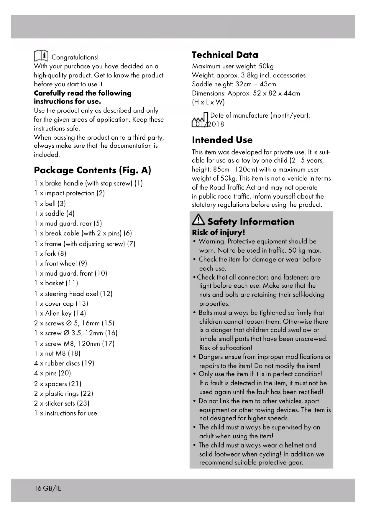
With your purchase you have decided on a high-quality product. Get to know the product before you start to use it.
Carefully read the following instructions for use.
Use the product only as described and only for the given areas of application. Keep these instructions safe.
When passing the product on to a third party, always make sure that the documentation is included.
Package Contents (Fig. A)
1 x brake handle (with stop-screw) (1) 1 x impact protection (2) 1 x bell (3) 1 x saddle (4) 1 x mud guard, rear (5) 1 x break cable (with 2 x pins) (6) 1 x frame (with adjusting screw) (7) 1 x fork (8) 1 x front wheel (9) 1 x mud guard, front (10) 1 x basket (11) 1 x steering head axel (12) 1 x cover cap (13) 1 x Allen key (14) 2 x screws ∅ 5, 16mm (15) 1 x screw ∅ 3,5, 12mm (16) 1 x screw M8, 120mm (17) 1 x nut M8 (18) 4 x rubber discs (19) 4 x pins (20) 2 x spacers (21) 2 x plastic rings (22) 2 x sticker sets (23) 1 x instructions for use
Technical Data
Maximum user weight: 50kg
Weight: approx. 3.8kg incl. accessories
Saddle height: 32cm - 43cm
Dimensions: Approx. 52 x 82 x 44cm
(H × L × W)

Date of manufacture (month/year):
2018
Intended Use
This item was developed for private use. It is suitable for use as a toy by one child (2 - 5 years, height: 85cm - 120cm) with a maximum user weight of 50kg. This item is not a vehicle in terms of the Road Traffic Act and may not operate in public road traffic. Inform yourself about the statutory regulations before using the product.

Safety Information
Risk of injury!
- Warning. Protective equipment should be worn. Not to be used in traffic. 50 kg max.
- Check the item for damage or wear before each use.
- Check that all connectors and fasteners are tight before each use. Make sure that the nuts and bolts are retaining their self-locking properties.
- Bolts must always be tightened so firmly that children cannot loosen them. Otherwise there is a danger that children could swallow or inhale small parts that have been unscrewed. Risk of suffocation!
- Dangers ensue from improper modifications or repairs to the item! Do not modify the item!
- Only use the item if it is in perfect condition! If a fault is detected in the item, it must not be used again until the fault has been rectified!
- Do not link the item to other vehicles, sport equipment or other towing devices. The item is not designed for higher speeds.
- The child must always be supervised by an adult when using the item!
- The child must always wear a helmet and solid footwear when cycling! In addition we recommend suitable protective gear.
- The item may not be used in the dark or when there is poor visibility!
- The item may not be used on sloping ground, or in the vicinity of stairs or open water! Avoid danger areas!
- Use the item only on appropriate surfaces, which are level, clean and dry. Keep away from other traffic users, if possible.
- The saddle height may only be adjusted by adults. Afterwards, fasten the screw tightly. The screw's tightness must be checked regularly.

Safety Instructions for Use
- Keep in mind that children often cannot correctly assess their own abilities and certain dangerous situations! Unforeseeable situations can arise due to children's play needs, for which the liability of the distributor/manufacturer is excluded.
- Do not let your child use the item unsupervised, since children cannot assess potential dangers.
- Teach the child how to handle the item properly and alert them to possible dangers!
- Be careful when using the toy. Skill is required to avoid falls or crashes, which can lead to injury of the user or other persons.
- The child must be confident that he/she is always in control of slowing down and braking the item. Practice slowing down and braking with the feet, as well as with the brake, before using the item.
- There is a danger of slipping on slippery surfaces! Bear in mind that the danger of falling exists when the item is being used.
Assembly

CAUTION!
Assembly of the item must always be
carried out by an adult!

CAUTION!
Keep children away from the item and the packaging materials during assembly. Risk of suffocation and choking due to small parts that can be swallowed or inhaled and risk of suffocation due to plastic bags.
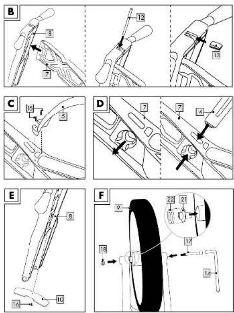
Assemble the Fork (Fig. B)
- Insert the frame (7) in the appropriate groove in the fork (8).
- Insert the steering head axel (12), from above, into the appropriate groove and affix it until it is flush.
- Slide the cover cap (13) on.
Affix Rear Mud Guard (Fig. C)
Affix the rear mud guard at the rear (5) with the 2 screws (15).
Affixing the Saddle (Fig. D)
- Screw off the adjusting screw.
- Insert the saddle (4) and screw the adjusting screw tightly again afterwards.
Affix Rear Mud Guard (Fig. E)
Turn the item around and affix the front (10) mud guard with the screw (16).
Mounting the Front Wheel (Fig. F)
⚠ Ensure that the nut (18) is inserted into the square groove, and the screw (17) into the round groove.
- Place the spacers (21) and the plastic rings (22) one after the other on both sides of the wheel axle.
- Insert the screw (17) on one side, into the opening of the fork, through the wheel, and through the other fork opening.
- Place the nut (18) onto the end of the screw, and screw it in with the Allen key (14).
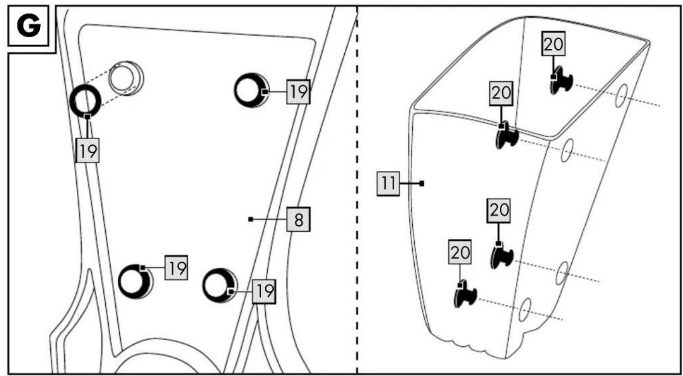
Mounting the Basket (Fig. G)
- Put the 4 rubber discs (19) into the places provided.
- Affix the basket (11) by pressing on the 4 pins (20).
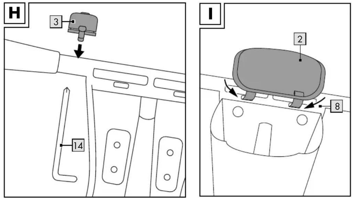
Mounting the Bell (optional) (Fig. H)
Loosen the screw on the bell (3), affix the bell on the left side of the handle bar and tighten the screw again afterwards.
Mounting Crash Protection (2) (Fig. I)
Pull the Velcro fasteners through the openings on the steering fork (8).
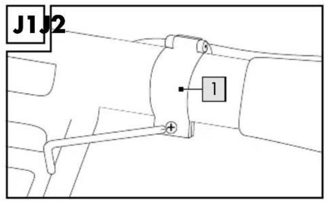
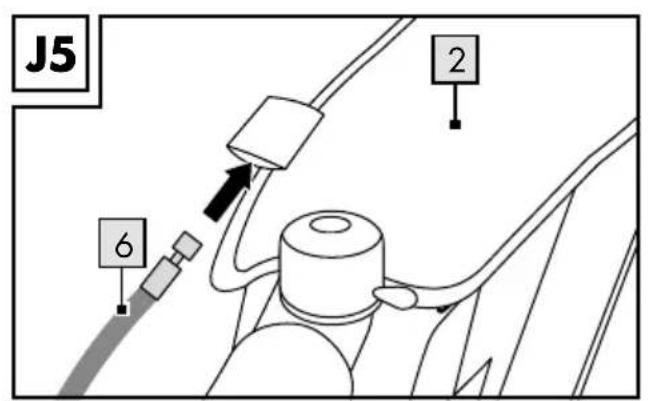
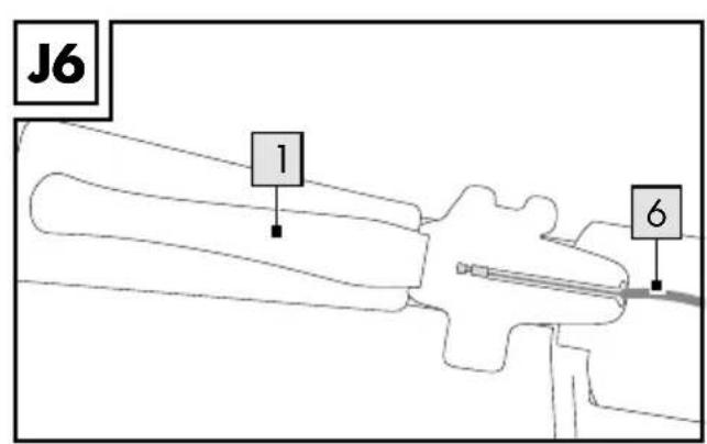
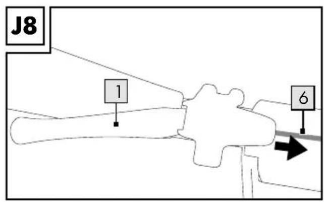
Assembling the Brake (optional) (Fig. J1 - J8)
CAUTION!
Should you decide to assemble the brake, it must always be adjusted (see Fig. M).
- Loosen the screw on the brake handle (1), affix the brake on the right side of the handlebar, and tighten the screw again afterwards.
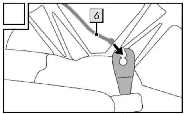
- Hook the brake cable (6) into the upper intake of the brake arm.
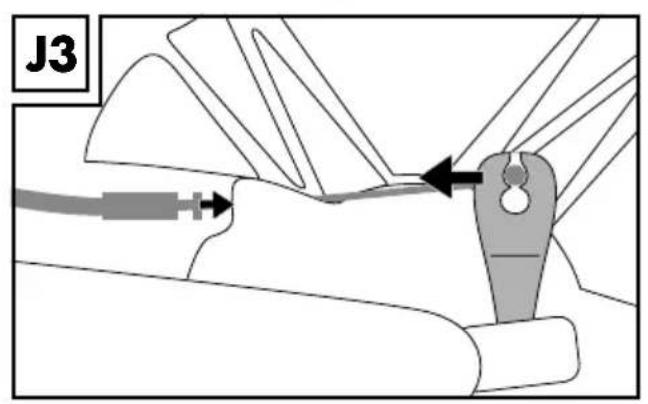
- Press the brake arm firmly in the direction of the arrow, and hook the adjustable lock nut into the duct.
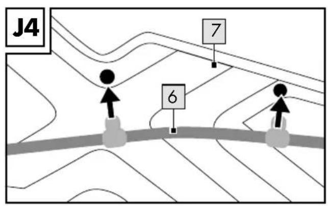
- Attach the brake cable (6) along the frame (7). Press the 2 pins on the brake cable into the opening provided on the frame.
- Thread the brake cable (6) through the lug on the crash protection (2).
- Pull the brake handle (1) and hook the abutment of the brake cable (6) into the groove provided on the handle (1).
- Press the brake arm in the direction of the arrow.
- Let the brake handle go and pull the brake cable (6) in the direction of the arrow until the end position is reached.
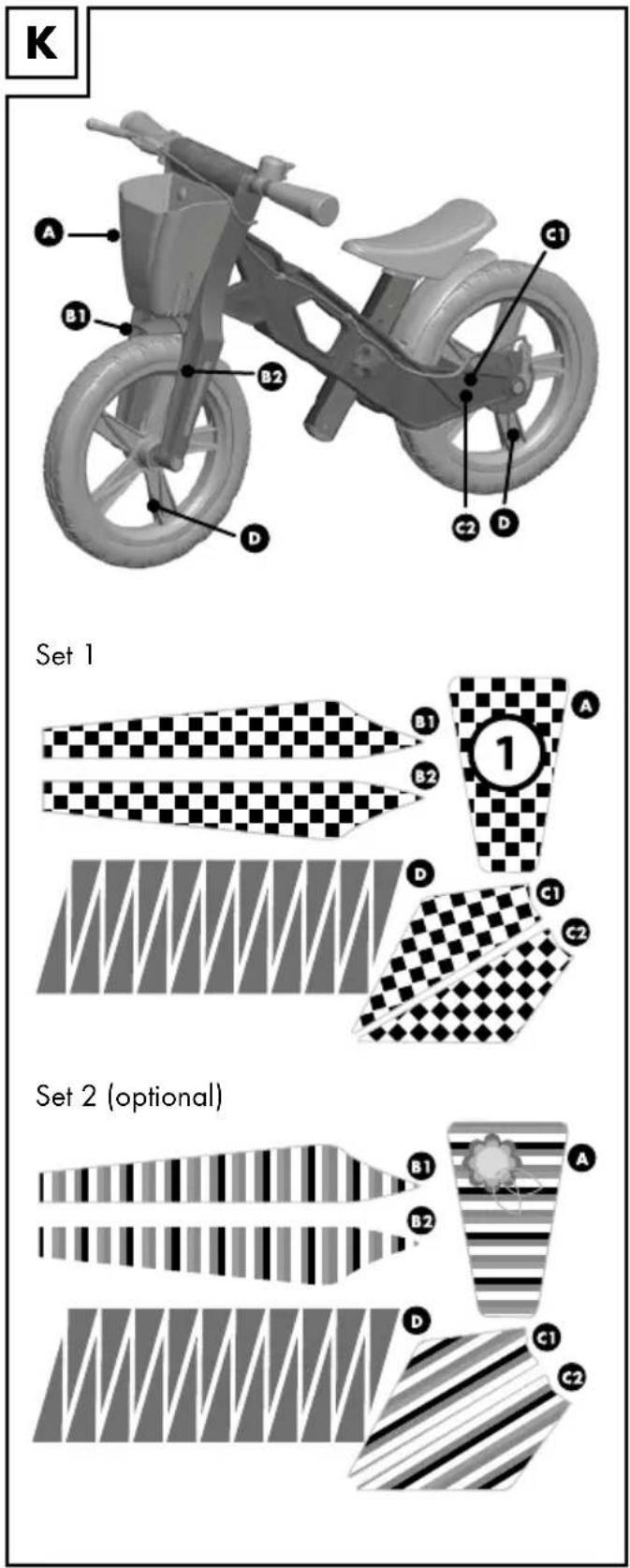
Attach stickers (Fig. K).
Remove the protective foil from the stickers and stick them onto the appropriate surfaces.
Settings
Brake
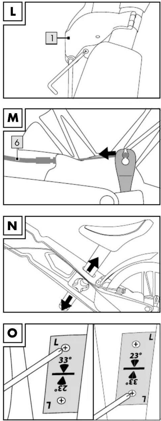
Brake handle (Fig. L).
Adjust the distance of the brake handle (1) to the grip by adjusting the stop screw (Fig. L).
Braking force (Fig. M) CAUTION!
The braking force must be set in such a way that the rear wheel spins freely when the brake handle is released, and jams when the brake handle is pulled.
Press the brake arm in the direction of the arrow. Turn the adjuster and the lock nut to the left to reduce the braking force, and turn the adjuster and lock nut to the right to increase the braking force (Fig. M).
Saddle Height (Fig. N) CAUTION!
The saddle height may only be adjusted by adults.
Note:
The saddle height is set correctly if the child can reach the ground securely with their feet.
Loosen the nut until the saddle can be pushed up or down. Set the saddle to the appropriate height, and tighten the nut again (Fig. N). The screw's tightness must be checked regularly.
Turning Angle (Fig. O)
The turning angle can be adjusted via two plates, either at 23 or 33 degrees. The lesser degree is appropriate for inexperienced riders, the higher degree is for children who are already confident with the use of the item.
IMPORTANT!
The plates must always be mounted on both sides, and have the identical degree of adjustment on both sides! The plate marked L, must always be mounted on the left, and the plate marked R, always on the right.
- On delivery, the plates are mounted with an angle of 33 degrees (33 is legible on both sides, above, Fig. O).
- To adjust the steering angle to 23 degrees, you remove 2 screws each, on both sides, turn the plates around (23 is legible on both sides, above), and afterwards tighten the screws again (Fig. O).
Care, Storage, Maintenance
We recommend thorough cleaning with water after using the item.
IMPORTANT! Clean the product with water only, do not use harsh cleaning products. Then wipe the item dry with a cleaning cloth. Always keep the item dry and clean in a temperature-controlled room. Every three months, put a drop of oil into the bearing bush of the handle bars and wheels.
Disposal
Dispose of the article and the packaging materials in accordance with current local regulations. Packaging materials such as foil bags are not suitable to be given to children. Keep the packaging materials out of the reach of children.
Notes on the guarantee and service handling
The product was produced with great care and under constant supervision. You receive a three-year warranty for this product from the date of purchase. Please retain your receipt.
The warranty applies only to material and workmanship and does not apply to misuse or improper handling. Your statutory rights, especially the warranty rights, are not affected by this warranty.
With regard to complaints, please contact the following service hotline or contact us by e-mail.
Our service employees will advise as to the subsequent procedure as quickly as possible.
We will be personally available to discuss the situation with you.
Any repairs under the warranty, statutory guarantees or through goodwill do not extend the warranty period. This also applies to replaced and repaired parts.
Repairs after the warranty are subject to a charge.
IAN: 295607
GB Service Great Britain
Tel.: 0871 5000 720
(£ 0.10/Min.)
E-Mail: deltasport@lidl.co.uk
IE Service Ireland
Tel.: 1890 930 034
(0.08 EUR/min., (peak))
(0.06 EUR/min., (off peak))
E-Mail: deltasport@lidl.ie

Congratulations!

- DE AT CH
- FR BE
- CAREFULLY READ THE FOLLOWING INSTRUCTIONS FOR USE
- PACKAGE CONTENTS (FIG. A)
- TECHNICAL DATA
- INTENDED USE
- SAFETY INFORMATION
- RISK OF INJURY
- SAFETY INSTRUCTIONS FOR USE
- ASSEMBLY
- CAUTION
- ASSEMBLE THE FORK (FIG. B)
- AFFIX REAR MUD GUARD (FIG. C)
- AFFIXING THE SADDLE (FIG. D)
- AFFIX REAR MUD GUARD (FIG. E)
- MOUNTING THE FRONT WHEEL (FIG. F)
- ⚠ ENSURE THAT THE NUT (18) IS INSERTED INTO THE SQUARE GROOVE, AND THE SCREW (17) INTO THE ROUND GROOVE
- MOUNTING THE BASKET (FIG. G)
- MOUNTING THE BELL (OPTIONAL) (FIG. H)
- MOUNTING CRASH PROTECTION (2) (FIG. I)
- ASSEMBLING THE BRAKE (OPTIONAL) (FIG. J1 - J8)
- SHOULD YOU DECIDE TO ASSEMBLE THE BRAKE, IT MUST ALWAYS BE ADJUSTED (SEE FIG. M)
- ATTACH STICKERS (FIG. K)
- SETTINGS
- BRAKE
- BRAKE HANDLE (FIG. L)
- BRAKING FORCE (FIG. M) CAUTION
- THE BRAKING FORCE MUST BE SET IN SUCH A WAY THAT THE REAR WHEEL SPINS FREELY WHEN THE BRAKE HANDLE IS RELEASED, AND JAMS WHEN THE BRAKE HANDLE IS PULLED
- SADDLE HEIGHT (FIG. N) CAUTION
- THE SADDLE HEIGHT MAY ONLY BE ADJUSTED BY ADULTS
- NOTE
- THE SADDLE HEIGHT IS SET CORRECTLY IF THE CHILD CAN REACH THE GROUND SECURELY WITH THEIR FEET
- TURNING ANGLE (FIG. O)
- IMPORTANT
- THE PLATES MUST ALWAYS BE MOUNTED ON BOTH SIDES, AND HAVE THE IDENTICAL DEGREE OF ADJUSTMENT ON BOTH SIDES! THE PLATE MARKED L, MUST ALWAYS BE MOUNTED ON THE LEFT, AND THE PLATE MARKED R, ALWAYS ON THE RIGHT
- CARE, STORAGE, MAINTENANCE
- DISPOSAL
- NOTES ON THE GUARANTEE AND SERVICE HANDLING
- CONGRATULATIONS
Brand : Playtive
Model : IAN 295607
Category : Balance bike