
MIG 1926K - Welding machine Güde - Free user manual and instructions
Find the device manual for free MIG 1926K Güde in PDF.
| Brand | Güde |
| Model | MIG 1926K |
| Product type | MIG/MAG welding machine with shielding gas |
| Power supply voltage | 230 V / 400 V single-phase, 50 Hz |
| Max. mains power | 16 A (fuse 16 A) |
| Open-circuit voltage (U0) | 25 – 40 V |
| Welding current range | 25 – 160 A |
| Weldable material thickness | 1 – 9 mm |
| Wire diameter | 0.6 – 1.0 mm |
| Duty cycle (ED) | 60% at 160 A (10 min cycle) |
| Protection class | IP 21 S |
| Insulation class | H |
| Weight | 39.1 kg |
| Dimensions (approx.) | Approx. 70 × 40 × 50 cm (with wheels and handle) |
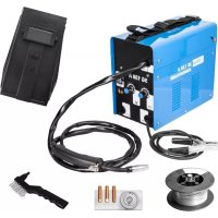
| Included equipment | MIG/MAG torch, ground clamp, welding mask, pressure regulator, Schuko-CEE 16 A adapter, spare nozzles, wire pulley |
| Voltage adjustment | 6 control steps |
| Wire speed | Continuously adjustable |
| Thermal protection | Yes, with indicator light and automatic reset after cooling |
| Shielding gas | CO2 or Ar/CO2 mixture, flow rate 6-10 l/min |
| Warranty | 24 months for end consumer, 12 months for industrial use |
Frequently Asked Questions - MIG 1926K Güde
User questions about MIG 1926K Güde
0 question about this device. Answer the ones you know or ask your own.
Ask a new question about this device
Download the instructions for your Welding machine in PDF format for free! Find your manual MIG 1926K - Güde and take your electronic device back in hand. On this page are published all the documents necessary for the use of your device. MIG 1926K by Güde.
USER MANUAL MIG 1926K Güde
Welders for manual welding in shielding gas with automatic wire feed enable jointing of metal parts by fusing the jointed edges and accessory material. Fusion is induced by an electric arc generated between the welded material and metal wire continuously protruding from the torch end and serving as accessory material for jointing of parts. Higher welding current allows welding of stronger sheets. We do not guarantee for damages caused by neglecting these instructions.
Product Overview
- This gas-shielded Welding Machine MAG series is designed for ease of welding. It conforms to the safety standard EN 60974-1. The device operates with single-phase input voltage and current at the output. It is mainly used for the welding of metals such as copper, steel, low carbon, low alloy steel, stainless steel, etc..
- This welding machine is mainly characterized by low cost, high productivity and resistance to corrosion. There welded slag-free. The unit is very versatile, and the welding can be done in any position.
- The welding machine is like a step up transformer built and has a built in wire feed and a feed roller. It is characterized by ease of use and low failure rate. The feed rollers can be configured to a range of between 0.5 to 5kg .
- The voltage can be adjusted gradually. Voltage and current can be adjusted to the thickness of the metal .. Multi-speed control of the wire feed .
- Constant voltage
- Equipped with indicator light, heat protection indicators and cooling fan.
- A device that is easy to carry.
- Accessories for the welding machine are : a MAG welding gun , a torch , a ground terminal and a welding hood.
The device is packaged in a carton.
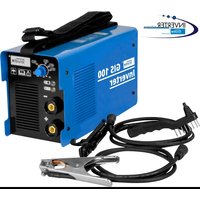
Welder in MIG 192/6K Shielding Gas
A compact upper-class welder for do-it-yourself works. With its 6 gear levels, it is also suitable for problematic welding. With fluently adjustable wire feed and rich accessories.
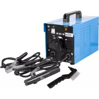
Equipment:
Welding shield and pressure control valve with two pressure indicators. 2 trundles at the back - 2 castor wheels in the front, including Schuko-CEE 16 A adapter, protections against thermal overloading and sets of 2-meter hoses.
- Welder with MIG 192/6K shielding gas
- Set of hoses
- Grounding terminal
- Spare nozzles and wire feed pulley
- Pressure control valve with 2 pressure indicators
- Power plug
- Plug with CEE 16 A earthing contact for 230V
- Welding shield
Warranty
A warranty period of 12 months applies to commercial use and 24 months apply to private use and commences on the day of purchase of the device.
Warranty applies exclusively to failures due to defective material or workmanship. An original sale slip with indication of date of sale must be presented in case of claiming for the warranty rights.
Warranty does not cover unprofessional use such as device overload, violent use, damage caused by third party or foreign materials, failure to comply with operations and assembly manual, and normal wear and tear.
General Safety Instructions
It is necessary to read through the entire Operating Instructions before first use of the appliance. If there are any doubts concerning connection and operation of the appliance, please contact the manufacturer (service department).
PAY ATTENTION TO THE FOLLOWING INSTRUCTIONS TO ENSURE HIGH SAFETY LEVEL:
ATTENTION!
Switch-on time
The appliance output is expressed by the "Einschaltdauer/Switch-on time" (ED%) data on the type label of the appliance, i.e. ratio between the welding and cooling time. This factor changes at the same appliance according to load conditions, i.e. according to the welding current delivered. It states how long the appliance may work in the given welding current when loaded and always relates to the time interval of 10 minutes. E.g. the appliance works continuously for 6 minutes at welding current for ED 60% . After this time there is a dead phase so that inner parts could cool down and protection against thermal overloading is restarted then.
Use of welders and execution of welding works may represent a danger both for person handling the appliance and for others. Therefore the person operating the welder is in all circumstances obliged not only to read the safety regulations given here but also know and observe them. It is necessary to always bear in mind that cautious, well-instructed operating staff strictly performing their duties is the best protection from injuries. You should read the regulations given in the following text and obey them before connection, preparation, use or transport of the appliance.
APPLIANCE INSTALLATION
- Installation and maintenance of the appliance must take place in accordance with local safety regulations.
- Pay attention to the state of wear of cables of connecting elements and plugs. They need to be replaced if damaged. Execute regular maintenance of the equipment. Use cables with sufficient cross-section only.
- Connect the grounding cable as near to the workplace as possible.
- Never use the appliance in a wet environment. Make sure the workplace, objects situated around and the welder were dry.
PERSONAL PROTECTION AND PROTECTION OF THIRD PARTIES
Radiation and heat are generated at the welding process. It is therefore necessary to ensure use of suitable protective means and take measures for personal protection and protection of third parties.
- Never expose yourself or other persons to electric arc or red hot metal effects without necessary protection.

Ensure suction of the welding smoke or good tion of the welding workplace.
PREVENTIVE MEASURES AGAINST FIRE AND EXPLOSION
Hot cinder parts and sparks may cause fire. Fire and explosion represent other danger. They can be prevented by observing the following rules:
- Do not use the appliance in immediate surroundings of easily combustible materials such as wood, wooden sawdust, "varnishes", solvents, petrol, petroleum, natural gas, acetylene, propane and similar inflammable materials. Remove them from the workplace or protect them against sparks.
- A suitable extinguisher needs to be around as a measure for fire extinguishing.
- Do not execute any welding or cutting works on closed vessels or tubes.
- Do not execute any welding or cutting works on vessels or tubes even when open if they contain or have contained any materials that could explode or elicit any dangerous reactions due to heat or moisture.
WELDER INSTALLATION
The following regulations must be observed at the welder installation:
- The operating staff must have free access to the operating elements and appliance connectors.
- It is not suitable to install the appliance in tight rooms: Sufficient welder ventilation is very important. Avoid heavily dusty or dirty rooms where the equipment could suck in dust or other objects.
The appliance (including cables) must not be an obstacle in passage or inhibit other persons from working.
It is necessary to work with the welder on a flat surface and use suitably secured gas bottle for its operation only.
Emergency Action
Apply the first aid adequate to the injury and get qualified medical assistance as quickly as possible. Protect the injured person from more accidents and calm him/her down.
For the sake of eventual accident, in accordance with DIN 13164, a workplace has to be fitted with a first-aid kit. It is essential to replace any used material in the first-aid kit immediately after it has been used. If you seek help, state the following pieces of information:
- Accident site
- Accident type
- Number of injured persons
- Injury type(s)
Marking on appliance
Explanation of symbols
The following symbols are used in these Instructions and/or on the appliance:
Product safety:
| CE | |
| Product is in accordance with appropriate standards of the European Community |
Prohibitions:
| Prohibition, general (in connection with any other icon) | Fire, open light source and no smoking |
| No cable pulling | Appliance not to be used when wet |
Warning:
| ! | |
| Warning/Attention | Warning against dangerous electric voltage |
| Warning against danger of trip | Warning against deleterious gases |
| Warning against hot surface |
Instructions:
| Use protective boots Use | protective gloves |
| Use protective clothes | Use a shield for face protection |
| Pull the power plug out before opening | Please read the Operating Instructions before use |
Environment protection:
| Do not throw waste to environment but dispose it properly. | Packing cardboard material may be delivered to collecting centres designed thereto. |
| Any damaged or liquidated electric or electronic devices must be delivered to appropriate collection centre.. |
Package:
| Protect against humidity This side up | |
| Interseroh Tensorrhynchus 6544 | |
| Interseroh-Recycling | |
Technical data:
| Network connection Network safeguarding | |
| MAG- welding material thickness | |
| IP 21 S | |
| protection | Weight |
| —— | |
| Welding transformer | Thermal protection |
| S | —— |
| In this environment, there is an increased risk of electric shock | single-phase transformer - rectifier |
| 1~50kA | |
Applicable safety standards: EN 60974-1:2005
U1: Rated Input Voltage (AC) (Tolerance ± 10%)
11max: Maximum rated input current
11eff: Maximum effective input current
X: load duration factor
Ratio of actual working time to total working time
Note 1: This factor is between 0 and 1 and can be specified with a percentage
Note 2: The default is meant by total working time a cycle of 10 min.
A load duration factor of 60% means, for example, that follow welding 4 to 6 minutes minutes idle.
U0: Open circuit voltage
Open-circuit voltage of the secondary coil
U2: Working voltage
Nominal output voltage during welding U2 = (14 +0.05 I2) V
A/V-A/V:Adjustment of welding current and in working voltage
IP: protection class example IP21S
H:insulation class
Intended Use
Welding machine for thermal compound of iron - ferrous metals by melting the edges and supply of an additional material.
Failure to comply with the provisions of the general regulations and the provisions of this manual, the manufacturer for damages can not be held responsible.
Residual risks and protective measures
Mechanical residual risks
| Threat Description Protective | measure Residual risk | ||
| Perforation, puncture | Hands can be perforated by wire | Wear protective gloves or keep hands in safe distance from wire exit. | |
| Liquid spraying | Spraying drops at welding can cause burns. | Wear protective clothes and welder's mask. |
Electric residual risks
| Threat Description Protective | measure Residual risk | ||
| Direct electric contact | Faulty cable or plug can cause electric shock. | Avoid contact with wet hands and ensure corresponding grounding |
Heat residual risks
| Threat Description Protective | measure Residual risk | ||
| Burns, chilblains | Contact with the hose nozzle and processed piece can cause burns. | Let the hose nozzle and processed piece cool down after operation finishing.Wear protective gloves. |
Exposure to radiation
| Threat Description Protective | measure Residual risk | ||
| Infrared, visible and ultraviolet light | Electric arc causes infrared and ultraviolet radiation | Always use a suitable protective welding shield, protective clothes and protective gloves. |
Exposure to processed material and other matters
| Threat Description Protective | measure Residual risk | ||
| Contact, aspiration | Long-term aspiration of welding gases can be harmful to health. | Use exhaust equipment when working or work in rooms with good ventilation. Avoid direct gas aspiration. | |
| Fire or explosion | Hot cinder and sparks can cause fire and explosion. | Never work with the appliance in an easily combustible environment. |
Other risks
| Threat Description Protective measure Residual risk | ||
| Slip, trip or fall of persons Slip, trip or fall of persons Keep your workplace clean |
Disposal
Disposal instructions are illustrated in the form of pictograms on the device or packaging. Description of the pictograms is given in "Identification" chapter.
Disposal of transport packaging
Packaging protects the device against damage during transport. Packaging materials are usually selected according to their effect on environment and disposal methods and can therefore be recycled. Returning of the packaging back to circulation saves resources and costs for packaging disposal. Parts of the packaging (e.g. foil, styropor) may be dangerous for children. Risk of suffocation! Keep these parts of the packaging out of reach of children and dispose as soon as possible.
Operation requirements
The operating staff must carefully read the Operating Instructions before appliance use.
Qualification
No professional qualification is needed for work with the appliance apart from the detailed training provided by a qualified expert.
Minimum age
Only persons above 18 years of age are allowed to work with the appliance. An exception includes cases when the appliance is used by a youngster within professional training to reach skills supervised by a trainer.
Training
Appliance use only requires appropriate instructions. No special training is needed.
Technical data
| Voltage | 230 V/400 V |
| Frequency | 50 Hz |
| Max. network output | 16 A |
| Protection | 40 V |
| Idle run voltage | 25-160 A |
| Control range 230 V | 115 A ~ 15 %/ |
| Control range 400 V | 160 A ~ 10%/ |
| Received material thickness | 1-9 mm |
| Switch-on time | 0,6-1,0 mm |
| Max. wire thickness | H |
| Insulation class | IP 21 S |
| Protection type 6 | |
| Gearing levels | 39,1 kg |
Transport and storing

Attention:
The appliance can be used and stored in an even working position (on a flat surface). Please respect the symbols on the package!
Make sure the gas bottle was well fixed and sealed.
Assembly and first putting into operation
Assembly set 1 - Assembly of wheels on the appliance: Fig.2, Fig.3, Fig.4
Assembly set 2 - Appliance handle assembly: Fig. 5 Assembly set 3 - Installation of the gas bottle on the appliance Fig.6, Fig.7
Assembly set 4 - Welder's shield assembly: Fig.8, Fig.9
Safety instructions for first putting into operation
-
Make sure the electric connection is sufficiently protected.
Use the prescribed protective clothes (pic.10). 1. Welder's helmet -
Welder's apron
-
Welding gloves
-
Ensure there are no other persons near the workplace or in dangerous areas.
- Make sure there are no flammable materials near the workplace.
- Plug the cable into appropriate outlet, the outlet must be protected by a safety fuse or power interlock switch.

on Installation only by qualified electricians!
Power factor (cos): 0.70
H07RN-F4G1.5 mm² power cable
H01N2-D 1*16 mm² welding cable
The power cable and any extension cable must have at least identical cross-section.
- ATTENTION! Electric safety is only guaranteed when the appliance is in accordance with valid regulations for electric equipment, properly connected to efficient grounding equipment.
- Check whether the power voltage and frequency you dispose of correspond to the data on the appliance type label.
Procedure
Proceed in the mentioned order at assembly of individual parts.
Keep correct layout of the assembly parts according to the given pictures. The appliance is not functional yet. Open the gas flow by 5-7 l/a min pressure. Protect the gas outlet against wind gust. In addition, it is necessary to respect the following information: The first switch levels 1-2 serve for welding of thin-walled sheets with other levels serving for thicker walls. Wire feed speed also needs to be set at each switch level change. If a drop is formed on the wire end at welding, the wire feed speed must be increased whereas if wire pressure is perceivable against the hose, you must reduce the speed. As parts being welded are very hot always use pliers if you want to move them and remove deposits on the torch end. As soon as the electric arc has been ignited hold the hose at an angle of app. 30irc to the perpendicular.
Welding wire installation pic. 11
1) Open the left side door of the welder by pulling the lever.
2) Insert the welding wire spool (weight depends on the appliance model) so that it was possible to pull the wire out of the spool at the top.
Caution: Make sure the wire did not uncoil from the spool and that its end was straight and without fray. The spool resistance can be adjusted to a fixing nut in the centre.
3) Open the turning knob.
4) Lift the stirrup element.
5) Check whether the grooves on the wire feed pulley correspond to the wire diameter and, if necessary, remove the wire pulley fixation by loosening the screws.
6) Position now the stirrup element and tighten the turning knob so that the wire on pulleys ran evenly. If the wire on pulleys slips, tighten more the turning knob. Attention: Do not tighten it too firmly as the extreme pressure to pulleys could cause damage to the wire feed engine.
7) Select 230V or 400V voltage. For 230V, use the supplied adapter plug, for 400V, connect the lead-in cable directly by CEE 16A red plug.
8) Now, switch on the welder by setting the selector voltage switch to voltage selected in point 7.
9) After you have checked that all safety measures have been taken set the changeover switch to level 1 and wire feed regulation to level 1.
10) Remove the gas nozzle and current nozzle and let the wire get out of the hose by pressing the pressure switch on the hose. Re-fit both nozzles subsequently.
11) Set the necessary gas volume on the gas bottle armature.
Tip: (0.6 mm-wire → 6 l/ an hour); (0.8 mm-wire → 8 l/ an hour); (1.0 mm-wire → 10 l/ an hour)
12) The appliance is now ready for welding.
General information on welding and shielding gas
The main area of application is in shops, can be applied universally, suitable both for thinner sheets and thicker materials. The more welding levels the appliance has, the better utilisation at work with sheets applies.
Necessary accessories: Co 2/Argon mixed gas, welding wire, welder's shield, pressure control valve. It is also suitable for aluminium and VA premium steel, using suitable gas and wire. (Clean argon/VA-wire/aluminium wire), potentiometer.
Control
- Connection of set of hoses
- Grounding terminal connection
- Wire feed speed setting
- Welding level setting
- 230V/400V selector switch
- "Thermal protection" signal light
- Operation signal light
- Power plug connection
Safety instructions fro operating staff
- Use the appliance only after you have carefully read the Operating Instructions.
- Respect all safety instructions mentioned in the Instructions.
- Behave responsibly to other persons.
- Attention!!! Never use a rusted welding wire.
Instructions step by step
The welded zone must be free of rust and varnish. Always use a protective welder's shield, welding gloves and suitable protective clothes. The angle of the set of hoses setting should be app. 30 degrees with respect to the processed piece.
- Polish a large surface on the processed piece at the weld seam and grounding terminal connection until glossy.
- Mount the grounding terminal to the prepared spot of the processed piece.
- Set parameters of the welder according to the user table for welding (chap. 3).
- Set necessary volume of gas on the gas bottle armature
- Tip: (0.6 mm-wire → 6 l/ an hour); (0.8 mm-wire → 8 l/ an hour); (1.0 mm-wire → 10 l/ an hour)
- You can start welding if you have protective clothes on.
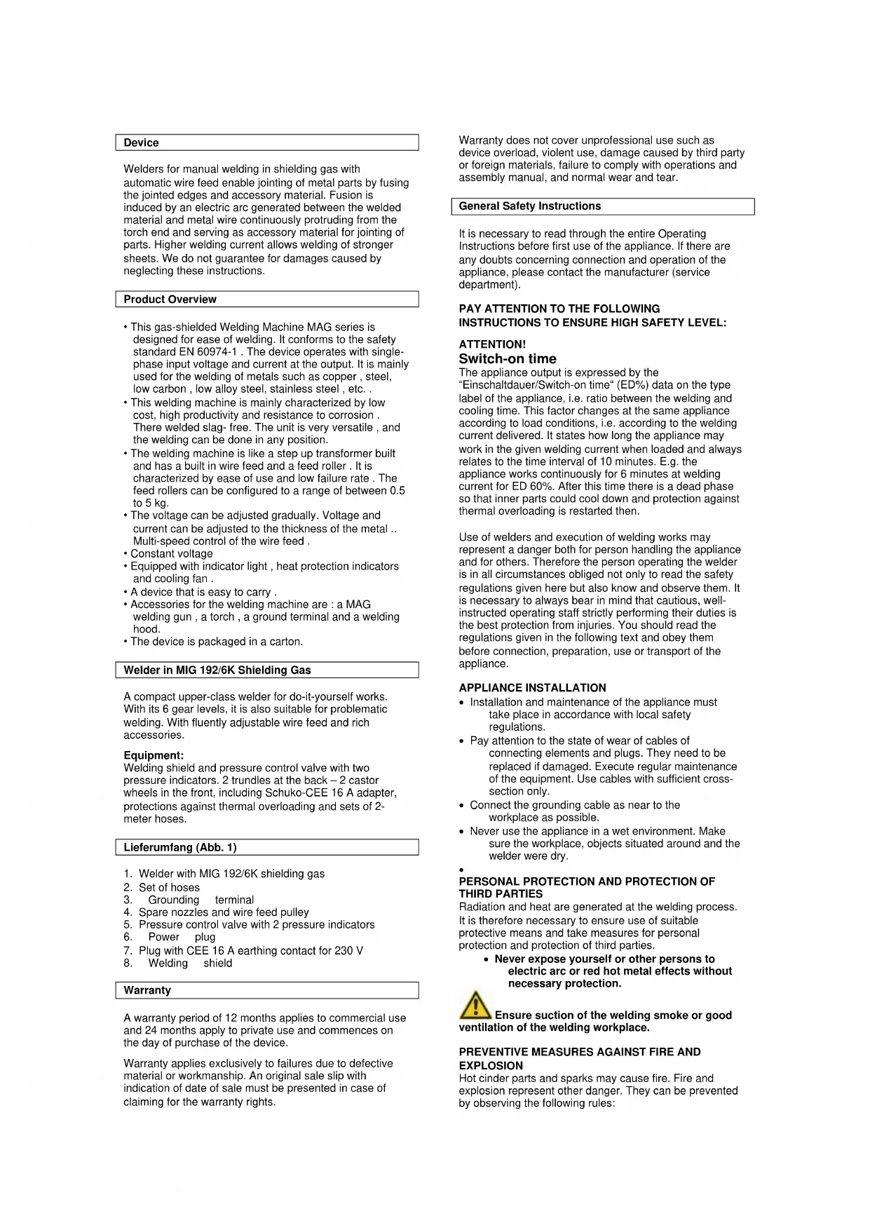
Tip: Before you start working do some testing welding to test the optimum setting of the welding parameters and reach an optimum result. Fig.14
Parameters for welding are set optimally when uniform noise is present and the welding seam is well penetrated in the material, i.e. it is relatively flat during work.
Tips for welding
| Failure Cause and remedy Example | ||
| The processed piece is awry | 1. Poor seam preparation2. Straighten the edges and fix them to the welding | |
| Weld elevation 1. Idle run | voltage is too low2. Welding speed is too low3. Faulty adjacent angle of the welding torch4. Too strong wire | |
| Small metal layer 1. Welding is too quick | 2. Too low voltage for welding speed | |
| Welds have oxidised appearance | 1. Weld in a pit with a long electric arc2. Set the voltage3. The wire is crooked or it excessively protrudes from the wire guidance4. Faulty wire feed speed | |
| Insufficient root welding | Irregular or insufficient distance2. Faulty adjacent angle of the welding torch3. Worn-out wire guidance tube4. Wire feed or welding speed is too low | |
| The processed piece is awry | 1. Wire feed speed is too high2. Faulty adjacent angle of the welding torch3. Too long distance | |
The welded zone should be free of rust and varnish. The torch is selected according to material type. We recommend first trying the current strength on a waste piece.
Failures - Causes - Removal
| Failure | Cause | Removal |
| The welding current falters | 1. The excessive temperature protection has failed due to overloading. | 1. The excessive temperature protection will automatically be reset after transformer has cooled down (after app. 10 minutes, pay attention to ED!) |
| The welding current is not available at all.The interlock power switch or RCD has failed | 1. The line fuse has failed | 1. Have the fuse checked2. Switch on the interlock power switch3. Switch on RCD |
| The welding current is not available. | 1. Poor contact between the grounding terminal and welded piece.2. Any failure in the grounding cable or grounding guide3. Any failure in the torch guide | 1. Clean and refine the welded area and part surface.2. Repair or replace the grounding cable.3. Repair or replace the torch. |
| The wire feed engine does not work, the signal light is switched on. | 1. The gear ring is failed or blocked.2. Faulty engine. | 1. Replace the gear ring.2. Replace the engine (contact your customer service). |
| The wire feed engine does not work, pulleys are turning. | 1. The pulley pressure is not set correctly.2. Impurities, dust, etc. on the torch current nozzle.3. Faulty gas nozzle.4. Warped wire.5. The wire guidance tube is dirty or damaged. | 1. Set the pulley pressure correctly.2. Clean the appliance contact tube. Use an air compressor for that. Replace the contact tube when heavily dirty.3. Replace the gas nozzle and check the edge.4. Check the pulley pressure and set it correctly if necessary.5. Clean it with compressed air and, if necessary, have the hose set replaced. |
| Wire feed is irregular. | 1. Impurities on the wire guidance. The gas nozzle is worn-out or faulty.2. The gas nozzle is clogged.3. There is an obstacle in the wire feed pulley guide.4. The wire feed pulley guide has been deformed.5. Faulty wire voltage. | 1. Clean the appliance wire guidance with air compressor.2. Replace the gas nozzle or contact tube.3. Clean or replace the gas nozzle.4. Clean the wire feed pulleys.5. Replace the wire feed pulleys.6. Set the wire voltage correctly. |
| Instable burning of the electric arc. | 1. Faulty wire speed setting.2. Impurities on the welded area.3. The gas nozzle is worn-out or faulty. | 1. Set the wire speed according to recommended parameters.2. Clean or polish the welded surface.3. Replace the gas nozzle and check the edge. |
| Welded seam is porous. | 1. No gas.2. The nozzle holder is clogged.3. Rusty or damp material.4. The torch is too far or you are holding it at a wrong angle to the welded spot. | 1. Open the gas and set the gas supply.2. Clean or replace the gas nozzle.3. Arrange the spot of welding properly or increase the gas supply.4. Clean or polish the material.5. The distance between the gas nozzle and processed piece must be 8-10 mm and the hose needs to be held at an angle of 30°.6. Check the rubber hose, connector and assemblage of the set of hoses - Press the gas nozzle down to a correct position. |
| The welding wire stops near the current nozzle. | 1. The current nozzle is worn-out.2. The welding wire is warped.3. The wire feed speed is too low. | 1. Replace the current nozzle.2. Check the pulley voltage pressure.3. Follow the wire feed speed instructions. |
| The welding pressure is irregular. | 1. The welding wire has been blocked on the spool. | 1. Check and, if necessary, adjust the pulley voltage pressure. |
| Penetration is too weak. | 1. Too weak welding current.2. Too long electric arc. | 1. Increase the welding current and wire feed.2. Hold the hose near the processed piece. |
| Penetration is too strong. | 1. Too high welding current.2. The wire feed speed is too low.3. Incorrect distance of the torch from the processed piece. | 1. Reduce the welding current and wire feed.2. Move the torch slowly and smoothly.3. The nozzle distance from the processed piece must be 8-10 mm. |
Inspection and maintenance
Hose set maintenance
Regular maintenance needs to be executed for perfect function of the hoses.
The gas nozzle needs to be regularly sprinkled by protective nozzle spray and freed of deposits inside.
The following steps need to be taken for this case:
- Remove the nozzle (1) by pulling forward
- Free the nozzle of any deposits formed by the weld cinder.
- Sprinkle it with protective nozzle spray.
- If the nozzle is rusty, it needs to be replaced.
Current nozzle maintenance
The following steps need to be taken for this case:
- Remove the nozzle (1) by pulling forward.
- Unscrew the current nozzle (2)
- Check whether the hole the wire goes through is not too wide or, in case of need, replace it before reassembly.
- Press the button on the hose so that the wire protruded and remount the current nozzle.
Nozzle holder maintenance
The following steps need to be taken for this case (see pic. 15):
- Holes for gas drainage can sometimes be slightly stuffed, in such a case the gas nozzle needs to be disassembled by pulling (1),
- unscrew then the current nozzle (2),
- unscrew the gas distributor (3) and replace with a new one.
Safety instructions for inspection and maintenance
Only a regularly maintained and treated appliance can become a reliable helper. Insufficient care and maintenance can be a cause of unpredictable accidents and injuries.
Service
Any technical questions? Complaint? Do you need spare parts or operation manual?
Go to our website www.guide.com and the section Service will help you quickly and without bureaucracy. Please, help us to help you. In order to identify your device in case of complaint, please indicate serial number, order number and year of manufacture. All information is available on the product label. To have all information always at hand, put them down.
Serial number:
Order number:
Year of manufacture:
Phone: +49 (0) 79 04 / 700-360
Fax: +49 (0) 79 04 / 700-51999
E-Mail: support@ts.guide.com
Important information for the customer
Please be sure to know that returning the product in or after the warranty period must be made in the original packaging.
| Time interval Description | Other | details |
| Remove the nozzle (1) by pulling forward. | Remove the nozzle (1) by pulling forward. |
Appareil
Manuale step by step
INSTALLATIE VAN HET APPARAAT
X: load duration factor
U0: Open circuit voltage
CnrypHocHa npoun3BedeHneTo:
| CE | |
| ПОНЗВЕДЕННО OTROВАРЯ На С bóТБЕТНITE HOPМИ В EC |
Verbote:
U1: Rated Input Voltage (AC) (Tolerance ± 10%)
11max: MaKcHMaJHa HOMHaJHa BXOJa TOnJIuHHa
MOLUHOCT TOK
11eff: MaKcImMaHa epeKtNBHa BXOeH TOK
X:HaTOBaBaHe npoDbJnxTeHnOCT paKTOp
CbtoHoueHHe Ha peaHHTo pa60THO Bpeme Ha o6uTo pa60THO BpeMe
3a6eEckka 1: To3nФakTop eMekdy O n mOke da
6bde onpeidenen c npoent
BeneKka 2: Np noPpa36npahe ce pa36npa noid o6oTo pa60THo BpeMe Ha uKbI OT 10 MNHTN.
AΦakTop npoDbJnxIteJIHOCT HaTOBapBaHe ot 60%
O3HaayBa, HApnMp, Ye CNeDbaT 3aBapraBaHe 4 Do 6
MNHyTN MNHyTN Ha npa3eH XoI.
U0: HanpeXeHne npn OToBopeHa Bepura
Open-HanpexeHne Ha BToPnHaTa HAmOtKa
U2:Pa6oTHo HanpeKeHne
HOMHaHNo HAppeKeHne no BpeMe Ha 3aBapBaHe U2 = (14 +0.05 I2) V
A/V-A/V:PerynnpaHe Ha 3abapbHnra TOK n B pa6oTHHO HAppeXeHne
IP: Hanpnmep knae Ha 3aunTa IP21S
H:130anaJnac
PpeHa3NaeHne
3aBapbHn MaHn H3a TOnHHa CbeHHeHne Ha XeJIa30 -CBETHN MeTAn Ype3 TOnHe Ha KpaIaTa I
npeIarHeTo Ha DonbHHTeNeH MaTePnaJ.
HeycnebxT da ce cb6pa3r c pa3npoe6nte Ha o6uNTe pa3npoe6n i pa3npoe6nte Ha TOBa p6koBOcTBO,Ha npOn3BOUHTen 3a BpeH He MoKe da 6bJe DbpxKaH OTROBOpE H.
OcTaBChn OnaHocTh N MepK 3a CnryphocT
MexAHueckn OCTaTbHn onaCHOCTn
ToJIHHHIOCTaTbUHN ONaCHOCTN
OnachoctOTn3JbYBaHe
MOHTaXHa rpyna 4-MoHTaX Ha 3aBapbHnA UJneM:
Φnr.8,Φnr.9
Hnctpykua 3a 6e3oanachocT npn pBpTO BbBexdahe Bekcnloatauia
Cb6nDaaBaiTe da 6bDe DocTaBHyO 3aunTeHO eNeKtpnueckTo npncBeHHeHne.
- N3noJ3BaIe npednicaHITe npedna3Hn 06neKna (ФИг.10).
1.3abapbueHwneM
2.3aBapbHa MaHTa
3. 3aBapbUH pKabUN
- OngpIXeTe ce OKO NO MCTOTO Ha pa60Ta eBENTyAINO B ONaCHATA 30Ha Da He Ce HAMnPAT NHKAKB DpyrN IIMua.
OrneaTe OKoNo MrcTo 3a paBoTa Da He ce HAMpaT 3anaNTeJIH MaTePnAn.
BkapaTte uenCeNa B c0tBeTHNHOKTAKT, KOHATAktbTp86Ba Da 6be3aunTe H ca3TOnem PpeDnAHTEN INI ppeDnAeH N3KNUChateN HA MOuHCT.

BHHMaHHe HcTaJauncaMoOT KBaJIINpHaH
eNeKToTeXHnIu!
-ΦaKTop (COS) MoUHocT: 0.70
H07RN-F4G1.5 mm² 3axpaHbaa Ka6eI
H01N2-D 1*16 mm2
Ka6eN 3aBpaBaHne IpeynpexKeHne Ka6eN MoKe da ce 3aMeHra cMoO T KBaInnFUnpaH nepcoHAn.
BHIMAHHE!EneKtpnueckKaTa 6e3onacHocTe oOCHypeHa cAmo Toraba, KoraTo anapaTbTe npaBnHO CBpb3Ah KbM eFKeKTHBNO 3a3EmRAuO cbOpBXeHHe Cnopei BaNNDHTe HOpMn 3a eNeKtpnueckn CbOpBXeHn.
- Поберетe,данинзлбаноте eнктческо
Нарженьи и сестоа отrobapгт ha даннite ot
Тиноья etiket ha anapata.
PocneIOBaTeHNOCT
PnMOHTnpaHToHaOTeJIHHTe cactn cna3BaTe fIrypAlHaTnocneDobatEnHOCT.
Cn3BaIte npabINHOTo pa3noJoxHe Ha MoHTnpaHITe
actIn cnopei. AnapatbT oue He e noTROBEN
da yHKUHOHa. OTBOpTe ra3a Da n3TNu C HAnrahe
5-7 m/MnN. N3nyckaHANr Ra3 nepeJa3BaIte OT Hanop Ha
Btbp.OCbeH ToBA Tp86Ba Da ce cbO6pa3BaTe CBc
CneHNTE uHFCOPMaUN: TpbNTe CTeneHn Ha
npBKBIOUbaTeI 1-2 clykAT 3a 3abapraBaHe Ha
TbHKOCTeHa JAmapHa, DOkATO OCTaHaJIte DBe CTeneHn
cLykAt 3a No-de6EJIu CTehn. PnP BCKa NpOMHa Ha
CTeEHnTE Ha npBekIOUbATEr Tp86Ba Da ce perynIPA u
CKOpocTTA Ha TENoONDaBAHeTO. Ako np3 3abapraBaHoTe ce
06pa3yBa HA Kpa HA TeNTA KAKA, Tp86Ba DA ce NOBUn
CKOpocTTA Ha TENoONDaBATeHNTO yCTpoCTBO AKO
6bPAtho YCbCTBaTe HATNC HA TeNTA IPOTNB UlnHaRa,
Tp86Ba DA CE HAMAI CKOpocTTA. Tb kato Toky uO
3aBapraBaHHTe YAcTn Ca MHO rOpeU, INoTBAWte
BnHarN KNeU, KOrAto NCKate Da rN MPbDHeTn d
OTcPaHHTe HAnocITE O KpA Ha rOpeKata. BeHara
CleD Kato CE 3anaN enEKTPNueckata Dbra, dpXkTe
ShNaHra NOD bTbn OKOno 30irc cnPMAO nepneHdkyIpa.
IpoBmuaHe Ha 3aBapbHata TeJ fnr.11
1) OTBopTe IeBnIcTpaHnueH Kanak Ha 3aBapbHnAnapat n3dbpNBAkNi ro 3a NoCTa.
2) NocTaBeTe poNkata CbC 3abApbUHaTate TEL (TertnoTo 3aBucn OT TUNa Ha anapaTa) Taka, Ye Da MoKe TeNTa da 6bDe n3dbpNaHa ot poNkata Harope.
Ipeynpexdne: O6bpHeTe BnHMaHne, da He ce pa3MOtaba TeJIa OT poKATA n KpaTn Da 6bJe paBEN 6e3 DeFopMaUN. CbnpoTnBHeMeTo Ha poKATA ce peryInpa c nomOuHa npTnraUata raKa Ha Dbpxkaa.
3) Pa3BnTe BbpTAAuBAHNT
4) NOBUNHHepe pAMOTO.
5) IpoBepTe daHn WnIcOBeTe B pONkata 3a NOdaBaHE Ha TEJIa OTTOBaprt Ha DmAMeTbpa Ha TEJIta, Ako e HeoBXOIMO CmKHeTe dbpKaHa HPONKATA 3a Teno KaTo paXna6Bte BoNTObete.
6) Cera Harnacepe pAMOTN 3aTgAraTe C Bbptuuece BNHT, DOKATO TENTa He 3anoVHe da CE HABINBa paBHOMepHO. AKO TENTa PpINMb3Ba Ha ponKITE, BNHTa OUe npnterHete. BHIMAHne: He 3aTARte MHORO CnHNO, B nPOTUBEN Cnyau npekaneHOTO HAJRAHE Bpxy PONKTE MoKe Da nobpeDN MOTopa 3a NODABAHe Ha TENTa.
7) ɪsèpète HαnpèkèHηne 230 V ἀπν 400 V. 3a 230 V nɪŋnəBaiTe DocTæbEHN ΜειCηeLηen aʌaNTop , 3a 400 V Cbþkète πριcβeɪnHηnteɪnna Kaβeɪ dɪpɛkTHo c nɒmòuHa YæpβeHηu Κεncel CCE 16A.
8) Cera KblnoTe 3aBapuHnAn apat Taka, Ye c npeBknObTaTeN 36peTe HnpeKeHne Cnpede N36paHOTo B TOka 7.
9) Cnaid KaTo cTe cnAaHb BCuKm MepKn 3a 6e3oNaChocT, NoCTaBeTe npeBknOyBaTeYr (fNr. 21/4) Ha 1 CTenEn H perynaIra Ta TeNoOnDaabaHTo (fNr. 21/3) Ha1 CTenEn.
10) CmBkHeTe ra3oBaTa n KOHTaTHaTa IIO3a n HAtnCKaIK N KHOKNaTa 3a HaJIraHe Ha WnHaRa n3KapaiTe TeNTa. CneI TOBA KOHTaTHaTa n ra3oBaTa IIO3a BbPheTe o6paTHo.
11) HarnaceTe Heo6xOIMMOTO KOINueCTBO ra3 Ha apMatypata Ha ra30BaTa 6byuNka.
Hae:(0,6 MM-TeN → 6 n/4); (0,8 MM-TeN → 8 n/4); (1,0 MM-TeN → 10 n/4)
12) Moxete Da 3aOnuHHe Ta 3aBapBaTe.
06uHΦopMaun 3a 3aBaprahe B 3aunTHara3oBa cpea
Главно ce n3non3BaВ pa6OtnHnUm, Иму yHbEpcaHnO npInnoxHeN,poXoJIO e KaKTo 3a TbKnIЯMapnHn, Taka n 3aNo-de6eMn MaTePnAn. Baxn npabnTo, Ye KOKOTO NOBceY cTeNeHn IMa anapA bT, TOnKOba no- RONMO e HerOBOTo pInnoXoe Hnp np pa6Otn CJaMapnHn.
Heo6xodmo 60bpyBahe:cmec ot ra3 Co 2/AproH, 3aBapyHa TeN, 3aBapyH NeuEM, peyuinpBeHTn. POnxoJIo e n 3a anyMmHn V A ne npa H CTOMaH npynotpeBa Ha noDxOJa Ra3 n TeN. (NcT aproH/VaTe/anyMNHeBa TeN), NoteHcHometbp.
06cnyxBaHe
- PnncbeDHHTeJ Ha WJNaHROBnKOMnNeKT
- PnncbeHnHTe Ha 3a3emBaauTe uinn (MaCA
- Perynaia Ha ckopoctn Ha TeIonoDaBaHaTeO
- PerynaunHa cTeenHtHa 3aBapBaHe
5.Ппевклочьтел 230V/400V - KoHTpOJHa JAMMa,ToTJIINHHa 3aUNTa
- KoHTponHa JAmna,eknnoataun
- PnncbEeHHeHne KbM MpeKaTa
PpeJn3Hm MepK 3a CnrypHocT npn 06cJyXbaHeTo
- I3noI3BaIe anapata Yak CneI ToBa, CneI KaTo CTc cn npOeyIN BHHMaTeIHO pbKOBoDCTBOTO 3a o6cnyKBAHe.
Cn3BaIe BCnKIMepKn 3a CnrypHOCT NOMEcTeHN ByyNbTBAHeTo.
BbTeBDbpKaHHeTO Cn OTROBOpN CnpraMO octaHaII Nua.
BHHMaHHe!! Hkora He n3non3BaIte pbxJcana 3aBapbYHa TeI.
YnbTbaHe CTbnKa no CtbnKa
Ha macto 3a 3abapbahe He Tp6Ba Da nHa Ma pBxda nn 60a. Pn npHnHn 3nON3BaTe PnpA3eH 3abapbueH 7IeM, npEpa3HN 3abapbCHN PbKABuNn N NOXo4o 6bn. Tbblt Ha HKnOHa 7naHra cnpmo 3abapbaHaTa aact 6n Tp6BaNo da 6bde Okono 30 rpaUca.
- N3bckaIte do 6nrcbk ronma nnou Bbpxy o6pa6oTBaHOTIO m3dJeNBE 06NaCTTa Ha 3aBapbYHn IeB INrTOTo 3a npCbeDInHeHne Ha 3a3EmBaUHTe uINKn.
- Ykpenete cera 3a3emraaunite uinnKaHa NOdrotBeHOTo MCTO Ha o6pa60TaHOTo H3dneHne.
- HactpoTe napaMeTpne Ha 3abapbHnna anapat cnopeedekcnloaTaunOHnHTe TaBnncn 3a 3abapBaHe (rnaBa.3).
- HactpoTe Heo6xOIMOTO KOINueCTBO Ra3 Ha apMaTypata Ha ra3ObTa 6ytnIka.
- Μιηρε: (0,6 MM-Teπ → 6 π/4); (0,8 MM-Teπ → 8 π/4); (1,0 MM-Teπ → 10 π/4)
- Ako Cte eknnpaH c KOMNKeTHo 3aunTHo 06JeKNO, MOKeTe Da 3aNoCHe Ta 3aBapBaTe.
IpeJn Da 3aOnOHTe NCTHCKOTo 3aBapBaHe,
N3BbPwTe NpO6Ha 3aBapKa, 3a Da npOBepNTe npABINHn
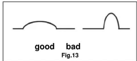
N3bOp Ha npAmeTpTE 3a 3aBapBaHe e 3a da
NoCTHHeTe ONTImaHn pezytATn. r.14
IapaMeTpnte 3a 3abapBaHe ca n36paHn ONTmMaJIHO TORaba, KORATO CE yBa eHaKBO INTeH3nBEH Wym IN 3abapyHnT Web NMa Do6p IpObapBaHe B MaTePnAna, Toec Tc e cpaBHTeHIO IIOcbK.
Iden 3a Do6po 3aBapBaHe
PoiIbpxKaHaKoHTaKTHataIIO3a
B To3n cIyau Tp86Ba Da ce NocTbNBA Taka (cnopeD cnir.15):
- CmBkHeTe IIO3aTa (1) n3IbPnBaNkn Ha nped
- Pa3BnTe KOHTaKTHaTa IIO3a (2)
- IpoBepTe OTBopa, npe3 KOIto MNHaba TeTta, da He e MHoro WnPOK, eBEHTyaJHO r CMeHeTe ppei Da ra MOHTnpate O6paTHo.
- HATNCHETe KHOHKATA Ha JIaNHa 3a Da N3Ne3e TEJI Ta IN CNEI TOBA KOHTAKTHA TIO3a OTHOBO MOHTHPaJTe.
IopdbpckKaHaHocayaI03a
BTo3n CnyaTpy6Ba Da ce NoctbNbTaKa (cnopeD
OTbOpITHe 3a n3yCKaHe Ha r3Ta MOrat da 6bDat NOHKAORA 3aApbCTeHn, Toraba e Heo6xOJMo Da ce CmBkA Ra3OBATA JIO3a KATO yN3dbPnate (1),
- CNEI TOBa pa3BnTe KOHTaKTHaTa IIO3a (2),
- pa3BnTe ra3Opa3PepEnTeTn (3) n ro cMeHeTe C HOB.
Mepkn 3a 6e3onacnoct npn pnernei n noDbpxka
Camo peoOBHO NOIbPkaH npeIeXdaH anapat MoKe Da 6bIe HAdEckHO NOMOuHO cpeCTBO.HeocTaTbUHaTa NOIbPka HrpKMOrAT da IpeDn3BkKaT HenpeDbNeH aAbpN u 3JIOJNYK.
Service
IMate JN TexHnueCKn Bbnpoc? PeknaMaun?
HeoXoDMn Jn Bn ca pe3epBn qactn nn ynbTbaHe 3a o6cnykBaHe?
Ha haata DomaHa cTpaHua www.guide.com B
pa3dien CepBn3 ue Bn nomorhem 6bp3o n 6e3
6bokpkaia. MoI NaomorHeTe Hn Da Bn nomorHem. 3a da
6bde Bb3MoKHO B cnUaH na peKnaMaunla Da
uDeHTnΦnUpaMe Baunna ypeH n e Heo6XoIM
cepHnHnHomeP, HomePa Ha 3a8BaKaTa n RoDInHa Ta
pano3BOcTBo. BcNkH Te3n DaHHn Ye hamePte Ha
Ta6eKnKaTa 3a Tnna. 3a Da MoKeTe Da NmTe 3eN DaHHn
BnHarNo pBka, MoIra 3aNNWeTe rN No-DoNY.
CepneH Homep
3aBka No
ToHnHa Ha npOn3BOdCTBO:
Ten.: +49 (0) 79 04 / 700-360
ΦaKc: +49 (0) 79 04 / 700-51999
E-Mail: support@ts.guide.com
BaxHn HΦopMaun 3a KneHeTa.
PpeDynpexdAme, Ye BpBuaHeTo no BpeMe Ha rapaunOHnncpok INN IN CneIrapaunOHnncpok e Heo6xOIMO BNHarN Da ce N3BpSn BOpINHnHa OnaKOBka. C Ta3n MprKa Ue Ce N36erHe N3InuHto YbpeKaDeNo BpeMe H TpaHcnpTupane H HerobOTO cecTo cnpoHO ypeKaHe. YctPoIcTBoTo e 3aUnTeHo ONTMAnHO CAMo BOpINHaHaTaOnaKOBKa, INaka e OcnYrpeHa PnabHa npepa60Ka.
11eff: Current maxim de efective de intrare
EC-DECLARATION OF CONFORMITY
We, hereby declare the conception and construction of the below mentioned appliances correspond - at the type of construction being launched - to appropriate basic safety and hygienic requirements of EC Directives. In case of any change to the appliance not discussed with us the Declaration expires.
DECLARATION CE DE CONFORMITE
PROHLASENI O SHODE EU
Tínto prohlasujeme my, ze koncepce a konstrukce uvedenych pristroju v provedenich, ktera uvadime do obéhu, odpovída prisluśný základnim požadavkum směrnic EU na bezpečnost a hygienu. V pripline dzeny pristroja, ktorá s nami nebola konzultovaná, stráca toho vyhlasnie svóju platnost.
VYHLASENIE O ZHODE EU
Tymto vyhalujeme my, ze koncepcia a konstrukcia uvedenych pristrojov vo vyhotoveniach, ktoré uvadzame do obehu, zodpoveda prislusnym zakladnym poziadavkam smernic EU na bezpečnost a hygienu. V pripadě zmeny pristroje, ktera s nami neblya konzultována, ztraci toho prohlášeni svou platnost.
EG-CONFORMITEITVERKLARING
English GB 8 Original Operating Instructions AUTOMATIK WELDING HELMET
To enjoy your new Automatic welding helmet as long as possible, please read carefully the Operating Instructions and the attached safety instructions before putting the appliance into operation. We also recommend keeping the Operating Instructions for future reference.
Making technical changes to improve the appliance as part of the continuous product development reserved.
This document represents the original Operating Instructions.
Supply includes
Take the Automatik 4/9-13 out of the transport container and check whether there are the following parts:
- Automatik 4/9-13 welding helmet
- 2 AAA micro batteries
- Original Operating Instructions
Warranty certificate
If any parts are missing or are damaged, please contact your dealer.
Appliance description
Extremely light helmet, though extremely stable and durable. Plastic material resistant to high thermal and mechanical load.
Fittings:
Adjustable continuous darkening DIN 9 to 13. Suitable for all welding processes with various lightness. Big auto darkening filter (90x45mm). Welding helmet is supplied by common batteries. Continuously adjustable band around head with padded front band. Manual switching using the Auto-Off function. Adjustable filter sensitivity.
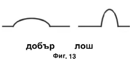
Product description (pic. 1, 2)
- Pre-fitted
- Auto darkening filter
- Welding
- Potentiometer for protection level selection (9 to 13)
- Filter holder
- Adjusting nut
- Screening
- Screening limitation
- Bolt
- Front band
- Band around head
- Solar cell
- Sensor
- Battery compartment
- Sensitivity controller
- On/Automatic off
Darkening instructions (pic. 3)
A. Electrode
B. MIG
C. MIG
D. WIG welding
E. CO2 MAG
F. Tubular cord electrode welding
G. Plasma arc cutting
H. Plasma arc welding
ding
welding
welding
welding
Technical specifications
Automatik 4/9-13 welding helmet
Sight glass size: 90 × 45 mm
Supply: 2 AAA micro batteries
Lightening and darkening
delay rate: 1/25,000 s
Darkening and lightening
delay rate: 0.4 s
Darkening level: from DIN 9 to DIN 13
Lightening level: DIN 4
Weight: 0.5 kg
General safety instructions

Please read carefully the Operating Instructions.
Familiarise with the control elements and appropriate use of the appliance. Keep the Operating Instructions for future reference.
Safe work
Keep the place of your work clean!
Mess in the place of your work may result in injuries.
Consider the environment
Do not expose the appliance to rain.
Do not use the appliance in a wet or moist environment.
Provide adequate lighting.
Keep other persons in a safe distance!
Do not let other persons, especially children, touch the appliance. Keep them in a sufficient distance from the place of your work. Behave responsibly to other persons.
Store the appliance properly!
An appliance that is not used should be kept in a dry, locked place inapproachable to children.
Do not overload your appliance!
Work within the specified output range.
Use the right appliance!
Do not use the appliance for purposes for which it has not been designed.
Look after your appliance!
Follow the servicing regulations and instructions.
Check regularly the appliance and have it replaced by an authorised professional if damaged.
Be careful!
Pay attention to what you are doing. Use common sense when working. Do not use the appliance when you are tired.
CAUTION!
Use of any other accessory equipment may lead to a risk of injury.
Have your appliance repaired by a professional only!
This appliance corresponds to appropriate safety regulations. Repairs may only be executed by a professional, using original spare parts; otherwise, the user will face a risk of injury.
Appliance-specific safety instructions

Appliance to be used only after reading the Operating Instructions.
- The Automatik welding helmet protects against intensive exposure, e.g. explosive
substances and fragments of abrading wheels and grinding wheels.
-
The Automatik welding helmet does not protect against splashing by dangerous and corrosive liquids.
-
The Automatik welding helmet is not suitable for oxy-acetylene welding, laser welding or welding works with a too low number of amperes.
-
Never weld with the Automatik welding helmet without being adequately instructed by qualified staff first.
-
Never open and handle the Automatik welding helmet electronic cassette. The manufacturer will not be liable for any consequential damage or injury.
-
Never leave the place of your work with the Automatik welding helmet being on as it could unexpectedly get dark and cause injury.
-
The Automatik welding helmet must never be exposed to excess temperatures.
-
Working temperature: -5ircC + 55ircC
-
Storage temperature: -20°C +70°C
-
Appropriate protective equipment must necessarily be worn for welding: safety shoes, utility gloves, protective glasses and closefitting clothing.
-
Check the Automatik welding helmet function every time it is to be used. Appropriate darkening must especially be provided for welding.
-
If the Automatik welding helmet or electronic cassette are damaged, you must not work with the Automatik welding helmet. Risk of injury! Any scratched or damaged foils must be immediately replaced.
-
Mineral filter foils may only be used in combination with an appropriate underlying foil.
-
Work under adequate visibility or lighting only.
-
Follow all safety instructions specified in the manual.
-
Parts of the Automatik welding helmet that may come into contact with skin may invoke an allergic reaction with sensitive persons.
Marking
Product safety:
| CE | |
| Product corresponds to appropriate EU standards |
Prohibitions:
| Protect against rain and moisture! |
Warning:
| ! | |
| Warning/Caution |
Commands:
| Do not touch these parts to prevent any burns. Learn to use the appliance before using it. |
Environment protection:
| PAP | |
| Dispose waste professionally so as not to harm the environment. | Packing cardboard material may be delivered to collecting centres for recycling. |
| Any faulty and/or disposed electric or electronic devices must be delivered to appropriate collection centres. |
Package:
| Interseroh Interseroh Interseroh Interseroh Interseroh | |
| - Protect against moisture - Fragile - This side up | Interseroh-Recycling |
Technical specifications:
| Sight glass size Power supply | |
| Lightening level Darkening level | |
| Lightening and darkening delay rate | Darkening and lightening delay rate |
| Weight | |
Helmet specification: GUEDE EN 175 S CE
GUEDE: manufacturer
EN 175: standard number
S: mechanical resistance: increased resistance
Pre-fitted glass specification: GUEDE S CE
GUEDE: manufacturer
S: mechanical resistance: increased resistance
Underlying foil specification: GUEDE S CE
GUEDE: manufacturer
1: optical class
S: mechanical resistance: increased resistance
Auto welding protective filter specification: 4-9-13 GUEDE S CE
4: lightening level
9: lowest darkening level
13: highest darkening level
GUEDE: manufacturer
1: optical class
3: scattered light class
1: homogeneity
3: angle-dependent light transmission level
379: used standard number
S: mechanical resistance: increased resistance
Training
Please read carefully the Operating Instructions and the servicing instructions. Familiarise thoroughly with the controls and proper using of the appliance. You must know how the appliance works and how controls can quickly be switched off. Never let children work with the appliance. Never let an adult person work with the appliance without proper training. Do not let any persons, especially small children and pets, to the place of your work. Be careful to prevent slipping or falling.
Use as designated
The Automatik 4/9-13 welding helmet has been approved to be solely used for the following:
Head and eye protection when welding by these methods:
- Electrode welding
MIG Fe welding
MIG AI welding
WIG welding
CO2 MAG welding - Tubular cord electrode welding
- Plasma arc cutting
- Plasma arc welding
The Automatik welding helmet is not suitable for oxyacetylene welding, laser welding or welding works with a too low number of amperes.
The appliance cannot be used for other works than those for which it has been designed and which are specified in these Operating Instructions.
Any other use will be considered a use in conflict with the designation. The manufacturer will not be liable for any consequential damage and injuries. Please be sure to know that the appliance has not been designed for industrial purposes.
Before using the appliance
Before using the fittings, please check whether all components of the Automatik welding helmet have been fitted properly.
Adjust the Automatik welding helmet considering the comfortable and perfect use and the required dimensions. Adjust the Automatik welding helmet bands using the bolt on the back side and appropriate holes on the band around head. The front part with the welding band must remain centred on the forehead.
Insert the batteries included in the supply. Respect the positive/negative pole.
Protective foils of the Automatik welding helmet must necessarily be removed before using the appliance for the first time; otherwise, auto darkening will not work properly.
The Automatik welding helmet must not be exposed to impacts, must not fall on the floor and never be exposed to excess temperatures.
Protection level selection
There are 5 protection levels (9 to 13) that can be adjusted during the welding process using the external potentiometer on the side of the helmet. After the welding process is initiated, the helmet gets automatically dark. Otherwise, please check whether the filter cassette has been switched on properly. Please follow the darkening instructions (pic. 3)
Sensitivity selection
Use the turning knob in the upper part of the filter cassette to adjust the sensitivity. This will prevent the welding process from being negatively affected by the change in the lightness in the environment.
LOW
Recommended for welding works with a high number of amperes and processes in an environment with intensive light.
HIGH
Recommended for welding works with a low number of amperes and processes in an environment with lack of light. Also recommended for permanent soldering works, e.g. TIG soldering.
Warranty
The warranty exclusively applies to material or manufacturing defects. Original purchase voucher with the purchase date must be provided for lodging a claim in the warranty period. The warranty does not cover any unauthorised use such as appliance overload, violent use, damage by a foreign person or an undesirable item. Failure to follow the Operating Instructions or assembly instructions and ordinary wear and tear are also excluded from the warranty.
Residual risks and protective measures
Other risks:
| Risk | Description | Protective | measure(s) |
| Eye injury No | solar radiation protection, e.g. at solar eclipse | Not to be used |
Behaviour in case of emergency
Provide necessary first aid treatment corresponding to the injury nature and seek qualified medical help as soon as possible. Protect the injured person from other injuries and calm him/her down.
First aid kit must always be available in the place of your work in case of accident in accordance with DIN 13164. Material taken out of the first aid kit needs to be supplemented right away.
If help is needed, please provide the following details:
- Place of accident
- Accident nature
- Number of injured persons
- Injury type
Disposal
The disposal instructions are based on icons placed on the appliance or its package. The description of the meanings can be found in the "Marking" section.
Transport package disposal
The package protects the appliance against damage during transport. Packing materials are usually chosen depending on their environmental friendliness and disposal method and can therefore be recycled.
Returning the package to material circulation saves raw materials and reduces waste disposal costs.
Parts of packages (e.g. foils, styropor) can be dangerous to children. Risk of suffocation!
Keep parts of packages away from children and dispose them as soon as possible.
Operator requirements
The operator must carefully read the Operating Instructions before using the appliance.
Qualification
No special qualification is necessary for using the appliance apart from detailed instruction by an expert.
Minimum age
The appliance can only be operated by persons over 18 years of age. An exception includes youngsters operating the appliance within their professional education to achieve necessary skills under trainer's supervision.
Training
Using the appliance only requires appropriate instructions by a professional or reading the Operating Instructions. No special training necessary.
Maintenance
Do you have any technical questions? A claim? Do you need spare parts or the Operating Instructions?
You will be helped quickly and without needless bureaucracy at our webpage www.guede.com in the Services part. Please help us be able to assist you. To be able to identify your appliance when claimed, we need to know its serial No., order No. and year of production. All these details can be found on the type label. Enter the details below for future reference.
Serial No.
Order No.
Year of production:
Tel.: +49 (0) 79 04 / 700-360
Fax: +49 (0) 79 04 / 700-51999
E-mail: support@ts.guede.com
Accessory equipment/spare parts
- Band around head 16957-010
- Fixation for band around head16957-01002
- Pre-fitted glass holder 16957-01003
- Potentiometer 16957-01004
- Pre-fitted glass 16957-01005
Transport and storage
Protect the Automatik shield against moisture and dust when being transported.
Servicing and cleaning
Protect the Automatik welding helmet, especially the electronic cassette, against liquids, in particular, corrosive liquids and dirt.
Clean the Automatik welding helmet and electronic cassette at regular intervals. In any case, do not use aggressive solvents or alcohol.
Make sure the sensors and solar cells are always clean. Clean them with a soft clean cloth (never plunge it in liquids).
Electronic cassette and filter cover change
Change the filter covers at regular intervals. Loosen the fastening screws of the filter cassette and remove the cassette. Filter covers can now be removed and changed.
Service life
The service life of these fittings especially depends on the maintenance and how the fittings are used. The fittings have no special applicability term; however, we recommend changing the Automatik welding helmet after 3 years.
Troubleshooting
The table below shows potential failures, their possible cause and remedy options. If the problem cannot be removed, contact a professional to help you.
| Symptoms | Possible cause | Remedy |
| Darkening pace is reducing | Low batteries Insert | new batteries |
| Darkening does not work | Darkening filter is switched offPoor batteries | Switch the darkening filter onInsert new batteries |
| Filter cover light transmission is too low | Filter cover is worn out | Remove the filter cover |
EU DECLARATION OF CONFORMITY
We,
Güde GmbH & Co. KG
Birkichstrasse 6
D-74549 Wolpertshausen
Germany,
herewith declare that the following appliance complies with the appropriate basic safety and health requirements of the EU Directives based on its design and type, as brought into circulation by us.
In case of alternation of the appliance, not agreed upon by us, this declaration will lose its validity.
Appliance specification:
AUTOMATIK 4/9-13 WELDING HELMET
Art. No.
16957
Applicable EU Directives:
89/686/EWG
Applicable harmonised standards:
EN 166/A3:2002-04
EN 379/A3:2009-07
EN 175/A3:1997-08
Place of certification:
Title of signatory: Managing Director
Mr
Technical documentation: J. Burkle FBL; QS
Arnold
Introduction


- Product Overview
- Welder in MIG 192/6K Shielding Gas
- Equipment:
- Warranty
- General Safety Instructions
- PAY ATTENTION TO THE FOLLOWING INSTRUCTIONS TO ENSURE HIGH SAFETY LEVEL:
- ATTENTION!
- Switch-on time
- APPLIANCE INSTALLATION
- PERSONAL PROTECTION AND PROTECTION OF THIRD PARTIES
- Ensure suction of the welding smoke or good tion of the welding workplace.
- PREVENTIVE MEASURES AGAINST FIRE AND EXPLOSION
- WELDER INSTALLATION
- Emergency Action
- Marking on appliance
- Explanation of symbols
- Product safety:
- Prohibitions:
- Warning:
- Instructions:
- Environment protection:
- Package:
- Intended Use
- Residual risks and protective measures
- Disposal
- Disposal of transport packaging
- Operation requirements
- Qualification
- Minimum age
- Training
- Technical data
- Transport and storing
- Attention:
- Assembly and first putting into operation
- Safety instructions for first putting into operation
- Procedure
- Welding wire installation pic. 11
- General information on welding and shielding gas
- Control
- Safety instructions fro operating staff
- Instructions step by step
- Tips for welding
- Inspection and maintenance
- Hose set maintenance
- Current nozzle maintenance
- The following steps need to be taken for this case:
- Nozzle holder maintenance
- The following steps need to be taken for this case (see pic. 15):
- Safety instructions for inspection and maintenance
- Service
- Any technical questions? Complaint? Do you need spare parts or operation manual?
- Serial number:
- Important information for the customer
- Appareil
- Manuale step by step
- INSTALLATIE VAN HET APPARAAT
- PpeHa3NaeHne
- Hnctpykua 3a 6e3oanachocT npn pBpTO BbBexdahe Bekcnloatauia
- PocneIOBaTeHNOCT
- IpoBmuaHe Ha 3aBapbHata TeJ fnr.11
- 06uHΦopMaun 3a 3aBaprahe B 3aunTHara3oBa cpea
- 06cnyxBaHe
- PpeJn3Hm MepK 3a CnrypHocT npn 06cJyXbaHeTo
- YnbTbaHe CTbnKa no CtbnKa
- PoiIbpxKaHaKoHTaKTHataIIO3a
- B To3n cIyau Tp86Ba Da ce NocTbNBA Taka (cnopeD cnir.15):
- IopdbpckKaHaHocayaI03a
- BTo3n CnyaTpy6Ba Da ce NoctbNbTaKa (cnopeD
- Mepkn 3a 6e3onacnoct npn pnernei n noDbpxka
- BaxHn HΦopMaun 3a KneHeTa.
- EC-DECLARATION OF CONFORMITY
- DECLARATION CE DE CONFORMITE
- PROHLASENI O SHODE EU
- VYHLASENIE O ZHODE EU
- EG-CONFORMITEITVERKLARING
- Supply includes
- Appliance description
- Fittings:
- Product description (pic. 1, 2)
- Darkening instructions (pic. 3)
- Safe work
- Consider the environment
- Store the appliance properly!
- Use the right appliance!
- Look after your appliance!
- Be careful!
- CAUTION!
- Have your appliance repaired by a professional only!
- Appliance-specific safety instructions
- Marking
- Helmet specification: GUEDE EN 175 S CE
- Pre-fitted glass specification: GUEDE S CE
- Underlying foil specification: GUEDE S CE
- Auto welding protective filter specification: 4-9-13 GUEDE S CE
- Use as designated
- Before using the appliance
- Protection level selection
- Sensitivity selection
- LOW
- HIGH
- Behaviour in case of emergency
- Transport package disposal
- Operator requirements
- Maintenance
- Accessory equipment/spare parts
- Transport and storage
- Servicing and cleaning
- Electronic cassette and filter cover change
- Service life
- Troubleshooting
- EU DECLARATION OF CONFORMITY
- Introduction
Brand : Güde
Model : MIG 1926K
Category : Welding machine