
DCU - Air Conditioning DOMETIC - Free user manual and instructions
Find the device manual for free DCU DOMETIC in PDF.

| Product Type | Self-contained Marine Air Conditioner |
| Brand | Dometic |
| Model | DCU (DCU series) |
| Available Capacities | 12,000, 16,000, 24,000, 30,000, 36,000 BTU/h (depending on version) |
| Power Supply | AC or high-voltage DC depending on model (see nameplate) |
| Refrigerant | R-32 (flammable, A2L) |
| Main Functions | Cooling, dehumidification, ventilation |
| Installation | By a certified technician; comply with local maritime regulations |
| Maintenance and Cleaning | Clean air filters regularly; check electrical connections and seawater circuit |
| Safety | Fire/explosion hazard (flammable refrigerant); electric shock hazard; requires grounding and equipotential bonding |
| Spare Parts and Repairability | Use only Dometic original parts; repair by qualified personnel |
| Warranty | Varies by country; 1 year minimum in Asia-Pacific region; refer to warranty document |
| Intended Use | Boats and yachts (marine use) |
| Seawater Operating Temperature | Min 4°C (40°F), max 30°C (86°F) |
| Seawater Pressure | Min 0.2 bar (2.9 psi), max 4.1 bar (60 psi) |
| Minimum Duct Dimensions | Depending on capacity: diameter from 100 to 200 mm (see specifications table) |
| Required Air Clearance | 400 mm (16 in) minimum in front of the return air grille |
| Electrical Protection | Dedicated circuit breaker; appropriately sized fuse or circuit breaker (see nameplate) |
| Disposal | Entrust to a specialist; contains fluorinated greenhouse gases |
Frequently Asked Questions - DCU DOMETIC
User questions about DCU DOMETIC
0 question about this device. Answer the ones you know or ask your own.
Ask a new question about this device
Download the instructions for your Air Conditioning in PDF format for free! Find your manual DCU - DOMETIC and take your electronic device back in hand. On this page are published all the documents necessary for the use of your device. DCU by DOMETIC.
USER MANUAL DCU DOMETIC
DCU, DLU, DTG, ECD, GT, GTX, GTX-LP, GVTX, TX
EN
Self-Contained Air Conditioning System
Installation Manual....(1)
DE
Self-Contained Air Conditioning System
Self-Contained Air Conditioning System
Instructions de montage.... 20
ES
Self-Contained Air Conditioning System
Self-Contained Air Conditioning System
Self-Contained Air Conditioning System
Self-Contained Air Conditioning System
Montagehandleiding....PQ
DA
Self-Contained Air Conditioning System
Self-Contained Air Conditioning System
Monteringsanvisning.... R4
NO
Self-Contained Air Conditioning System
Monteringsanvisning.... S2
F!
Self-Contained Air Conditioning System
Asennusohje....T0
PL
Self-Contained Air Conditioning System
Cancer and Reproductive Harm
www.P65Warnings.ca.gov
SK
Self-Contained Air Conditioning System
Návod na montáz....J OR
CS
Self-Contained Air Conditioning System
Self-Contained Air Conditioning System
Self-Contained Air Conditioning System
Self-Contained Air Conditioning System
Montaj ' (lavuzu....J 42
SL
Self-Contained Air Conditioning System
Navodilo za montažo.... J PO
0
Self-Contained Air Conditioning System
Instruc)iuni de montaj....JPT
BG
Self-Contained Air Conditioning System
Ин, - /0123 45 67н-58.....] GS
ET
Self-Contained Air Conditioning System
Self-Contained Air Conditioning System
Self-Contained Air Conditioning System
Self-Contained Air Conditioning System
Uzst: dšanas rokasgr: mata....202
Copyright t
© 2024 Aometric Broup. Che visual appearance of the contents of this manual is protected EF copFright and design laG. Che underIFing technical design and the products contained herein maF Ee protected EF designH patent or pending patent. Che trademarks mentioned in this manual Eelong to Aometric ! Geden AI . All rights are reserved.
Englis'
J Important notes....(v)
2 KLplanation of sFmEols....M
M Carget group's 4
4 Intended use....4
P KLplanation of sFmEols on the device....4
Q 9re-installation....4
R Installation....0
S Aisposal....T
T Cechnical data....T
J0 Jegal....J0
JJ V arrantF....J0
) !important notes
Please read these instructions carefully and likely all instructional guidelines and Garnings included in this product manual in order to ensure that Fou install user and maintain the product proper at all times. These instructions MU C staff Gth this product.
If the product's for here?E confirms that Fou have read all instructions! guidelines and Garnings call full and that Fou understand and agree to date it the terms and conditions as set forth herein. You agree to use this product onl for the intended purpose and application and in accordance with the instructions! guidelines and Garnings as set forth in this product manual as Cell as in accordance with all applicable laqs and regulations. A failure to read and folio the instructions and Garnings set forth herein made in an injure to counsel and other damage to your product or damage to other property in the vicinity. This product manual including the instructions: guidelines and Garnings and related documentationi ma? Ee suEject to changes and updates. Your up-to-date product information please visit documents.dsnmrc.com,
2 Explanation of sym, ols
A signal Gord Gill identiF safetF messages and propertF damage messages+ and also Gill indicate the degree or level of hazard seriousness.

DANGE - Indicates a hazardous situation that I'd not avoided Gill result in death or serious injurf.

. A NING- Indicates a hazardous situation that it not avoided could result in death or serious injurF.

NOTICE- Indicates a situation that it is not avoided can result in property damage.

NOTE ! upplementarF information for operating the product.
2/) S0ppplemental dire1ti2es
Co reduce the risk of accidents and injuries please serve the following directives. Before proceeding to install this appliance?
[ Read and folloG all saCetF information and instructions.
[ Read and understand these instructions Before installing this product.
[ Che installation must complF Gith all applicaEle local or national codes- including the latest edition of the folloGing standards?
[ American | oat and Xacht ] ouncil |AI| X]
[AN! I/NY9A R0- National Electrical ] ode [NK]
2/2 Safety instr01tions

DANGE - is3 of fire or explosion/ Some models 0se flamma, le refrigerant/
Yailure to oEeF the JolloGing Garnings Gill result in death or serious injurFZ
Co Ee repaired onlF EF trained service personnel.
Ao not install or store in a location Gith continuousF operating sources of ignition.
Maintain all required ventilation openings free from oEstructions.
Ao not puncture refrigerant tuEing.
Refer to the product data plate for refrigerant tFpe.

. A NING- Fire and4or explosion 'a5ard Yailure to oEeF the JolloGing Garnings could result in death or serious injurF?
Ao not use potential sources of ignition to detect or search for refrigerant leaks. Ao not use a halide torch or anF other detector that uses a naked flame.
I e sure that detection equipment is suitable for the refrigerant tFpe used in the product. Refer to the product data plate for the refrigerant tFpe.
Klechnic leak detectors maF Ee used to detect refrigerant leaks in hoGever their sensitivit F maF Ee inadequate for flammaEle refrigerants and maF need recalEration. ] aliErate detection equipment in a refrigerant-free area.

. A NING-Car, on monoxide 'a5ard Yailure to oEeF the JolloGing Garnings could result in death or serious injurF?
Ao not install or operate a self-contained air conditioner in the Eilge or engine room area/h or near an internal comEustion engine. Knsure that the selected location is sealed from direct access to Eilge and/or engine room vapors.
aerIF the condensate drain line is properIF installed and sealed. Ao not end the condensate drain line Github M b, 30.Tj m0 o0 anF outlet o0 an engine or generator eLhaust sFstemH in a compartment containing an engine or generator or in a EilgeH unless the drain is connected properIF to a sealed condensate or shoGer sump pump. If the drain line is not properIF installedD dangerous fumes maF travel up the drain line and contaminate the living quarters.
Ao not install the air conditioner in a location Ghere it can circulate carEon monoLideH fuel vaporsh or other noLious fumes into the Eoats living spaces.

. A NING-Ele1tro10tion 'a5ard Che installation maF onlF Ee carried out EF a qualified electrician.

A NING- Eletrilal s' o13, fire and4or explosion ' a5ard Failure to folloG these precautions could result in death or serious injurF. This appliance is not intended for use EF persons including children. Gith reduced phSical sensorE or mental capaEilities or lack of experience and knoGledge unless theF have Eeen given supervision or instruction eOut the use of the appliance EF a person responsiEle for their saetF. ] hildren should Ee supervised to ensure that theF do not plaF Gith the appliance. ] leaning and user maintenance shall not Ee made EF children Githout supervision. This appliance should not Ee accessiEle to the general puElic.

. A NING- Explosion 'a5ard Yailure to lolloG these precautions could result in death or serious injurF.
Ao not install the air conditioner in a location containing gasoline engines tanks 09B /] 9B cFlindersl regulatorsll valvesll or fuel line Wttings. Unless laEeled otherGiseI sell-contained units do not meet federal requirements for ignition protection. Failure to oEeF this Gaining could result in death or serious injurF.
Electrical components that can arc or spark shall only be replaced with parts specified by the appliance manufacturer. Replacement with other parts may result in the ignition of refrigerant in the event of a leak.
EN[1]
![DOMETIC DCU - EN[1] - 1](/content/2026/03/549804/images/9b70ad7aec040effc9fc8c96a808319086dc8344982fbb222a5b1f50948d6e82.jpg)
. A NING- Eletrilal s' o13 'a5ard
Yailure to JolloG these precautions could result in death or serious injurF.
I e sure to effective ground the air conditioner to minimize the electrical shock hazard. Refer to the installation guidelines for further information.
Kach air conditioner installed requires a dedicated circuit Breaker. D there is only one air conditioner installed the seaGater pump does not require a dedicated circuit Breaker. D tGo or more air conditioning units use the same seaGater pump the pump Gires Gill Ee connected to a pump rela panel 9R90- Ghich in turn has its oGn dedicated circuit Breaker sized for the pump 20 A maL. Refer to the Giring diagram furnished Gith the 9R9. Electrical connections in the Elge and/or EeloG the Gaterline should use heat shrink fpe Eutt splices.
Yield Giring must complF Gith A1 X] electrical codes. 9oGer to the unit must Ee Githin the operating voltage range indicated on the data plate. 9properF sized [uses or e A] R circuit Breakers must Ee installed for Eranch circuit protection. I ee the data plate for the maximum use/circuit Breaker size HMY10 and minimum circuit capacitF HM] A0.
![DOMETIC DCU - EN[1] - 2](/content/2026/03/549804/images/747b8b0f1f4c177b57a684581e53aa3bd741a8e10732971cf2e01d5f66a5b798.jpg)
NOTICE-
This appliance has fluorinated greenhouse gases in hermeticalF sealed equipment. Refer to the condensing units product data plate laEel for the quantitF of refrigerant shoGn in Geight and BV 9. Che refrigerant added should Ee noted on the unit laEel.
![DOMETIC DCU - EN[1] - 3](/content/2026/03/549804/images/4f48c9ffd51d3b6e358384d20512409a31e2d27e362f4f8faac7d974f7bf50d3.jpg)
NOT!CE-
Ao not use the copper tuEing to pushH pullH libH or carrF the product.
6 Target gro0p7s8

The mechanical and electrical installation and setup of the device must Ee performed EF a qualified technician Gho has demonstrated skill and knoGledge related to the construction and operation of marine equipment and installations and Gho is familiar Gith the applicaEle regulations of the countrF in Chich the equipment is to Ee installed and/or used and has received safety training to identify and avoid the hazards involved.
9 !Intended 0se
This manual is intended for the installation of A] U-AUU-ACB+K] AF-BCH B Cf H B Cf - U9r B aCfF and Cf sel-contained air conditioning sFstems whereinaber referred to as air conditioner. The air conditioner is intended for use on Eoats and Fachts. This air conditioner is onlyf suitaEle for the intended purpose and application in accordance Gith these instructions.
This product is onIF suitaEle for the intended purpose and application in accordance Gith these instructions.
This manual provides information that is necessary for proper installation and/or operation of the product. Good installation and/or improper operation or maintenance Gill result in unsatisfactor performance and a possiEle failure.
Che manufacturer accepts no liaEilitF for anF injurF or damage to the product resulting from?
[ Incorrect installationH assemEIF or connectionH including eLcess voltage
[ Incorrect maintenance or use of spare parts other than original spare parts provided EF the manufacturer
[ Alterations to the product Gwithout eLpress permission from the manufacturer
[ Use for purposes other than those described in this manual
Aometic reserves the right to change product appearance and product specifications.
: Explanation of sym, ols on t' e de2i1e

V armingg Risk of 'tre / YlammaEle materials

V arming; LoG Eurning velocitF material. YlammaEle refrigerant.
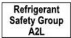
Refrigerant safety group A2J
Read operating manual.

Read service manual.
6 Pre-installation

NOTICE-
Che ACB + B Cf + B a Cf II and Cf self-contained condensate Ease pans are equipped Gith viEration isolators installed in the Eottom of the pan. These isolators are designed to dampen the viEration caused EF the operating air conditioner from transferring into the mounted surface. ] are must Ee taken Chen moving the air conditioner across mounting surfaces as the isolators can Ee damaged.

NOTICE-
Che air conditioner must Ee mounted to a loG+ flat+ level surface+ like in the Ebottom of a lockerH under a Eunk or dinette seat+ or in a similar location.
Knsure that the caEling Gill not Ee suEject to Gearl corrosionl eLcessive pressurel viErationl sharp edgesl or anF other adverse environmental edectsll including edects from aging or continual viErationl from sources such as compressors or fans.
Knsure that protection devices- piping ^b and Wittings are protected as far as possiEle against adverse environmental effect such as dirt and deEris accumulation or Gater collecting and freezing in relief pipes.
9 precautions should Ee taken to avoid eLcessive viEration or pulsation to the refrigerating piping.
6/) Determining t' e installation lo1ation
J. BaCf and Cf placement relative to airfloG
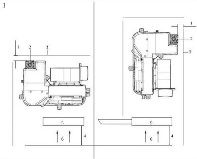
) M.00 in RQ2 cm
9 4.00 in NJ 0J Q cm ^2
2 e eat sink : Return air grille
6 | ulkhead 6 AirloG
All other air conditioning units placement relative to airfloG
) 4.00 in N J G cm ^3
9 M.00 in MRQ2 cm
2 Return air grille : 1 ulkhead
6 AirCloG
- ] choose a location Gith enough airfloG. Che return air grille should have a minimum of 4.00 in ∥ 0.1 G cm ^2 or air circulation clearance in front of it free from anF oEstruction.
M. 10 the air conditioner is positioned perpendicular to the return air grille- maintain a minimum of M.00 in MRQ2 cm/ air circulation clearance on the air intake side. - GVTX and TX only: 9 provide a minimum open area of M.00 in IR.02 cm ^3 aEove and EeloG the heat sink.
6/2 otating t' e, lower
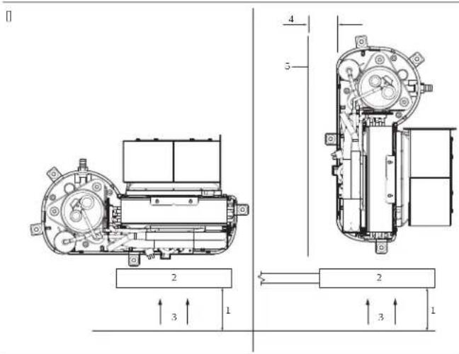
This section eLplains hoG to rotate the EloGer for each unit tFpe. It needed to rotate the EloGer to the direction that alloGs the most direct airfloG discharge through the ducting.
6/2/) GTX, GVTX, DTG, and TX, lowers
B Cf + B a Cf + A C B H and Cf sFstem EloGer rotation
) Adjustment screG
2 | loGer
-
Loosen the adjustment screG on the EloGer mount ring.
-
Rotate the EloGer to the desired position.
M. Cighten the adjustment screG.
6/2/2 MCS, ECD and GT, lowers
M] !HK] A+ and BC sfstem EloGer rotation
EN
)!creG
29late
6 | loGer
]. Remove the seven screGs on the plate.
2. Rotate the EloGer to the desired position.
M. I secure the EloGer in place using self-tapping screGs (not provided).
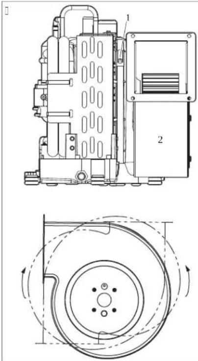
6/2/6 DCU, lower
A] U sFstem EloGer rotation
)! creGs on EloGer ring
2 ! creGs on drain pan or Eracket
J. Remove the screGs from the EloGer ring.
2. Remove the screGs attaching the EloGer to the drain pan or Eracket.
M. Rotate the EloGer to the desired position,
4. I secure the EloGer in place using self-tapping screGs (not provided).
P. 9lug anF unused holes to prevent air loss.
6/6 Plating t' e air filters
Air Wters remove airEorne particles from the caEin air and keep the evaporator coil clean. 9 place one air Witer+ either on the air conditioner or in the return air grilleH Dor each air conditioner.
6/9 Pla1ing t' e grilles and transition, oxes
] onsider the JolloGing Ghen placing the grilles and transition EoLes?
[ Install the supplF air grille as high as possiEle in a location that Gill give uniform air distriEution throughout the caEin. Airect the grille louvers upGard.
[ Install the return air grille as loG and close to the air conditioner as possiEle to ensure airfloG to the evaporator.
Ao not direct the supplF air discharge toGards the return air grille as this Gill cause the sFstem to short cFcle.
| AlloG for adequate clearance E behind the supplF air grille for the transition Eol and ducting connection. Refer to ! specifications on page J 0
7 !Installation

. A N!NG- Ele1tro10tion 'a5ard
Che installation maF onlF Ee carried out EF a qualified electrician.
7/) Installing t' e mo0nting, ra13ets and 1ondensate drain

NOT!CE-
Co prevent cracking the drain pan do not use more than tGo laFers o)
plumEers tape to Grap the hose EarE and do not overtighten the hose EarE.
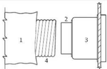
CFpical placement of mounting Erackets and condensate drains
natural_image
Technical line drawings of two mechanical components, one open and one closed, with no visible text or symbols.) ] ondensate drain hose EarE
2 Mounting Eracket
] ondensate drain installation for B Cf + B a Cf + ACB H and Cf
) e ose EarE 9 Arain pan
2 Chreaded drain hole : Arain hose
6 ! lug knockout
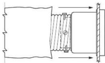
] ondensate drain installation for all other air conditioning units
) Ucking nut 9 ! olid Gasher
2 Arain pan
: 9a | Citting 0.P in ∥2.R mm∅ c | L 0.P in ∥2.R mm∅ M9C
6 Liquid-seal Gasher
- Yor B Cf + Ba Cf + ACB and Cf units?
a) Use the small end of the hose EarE to knock out a slug from an ab-facing drain hole EF applFing one quick strike Cith a ruEEer mallet. Aiscard the slug knockout.
E0V rap the threaded end of the hose EarE Gith plumEers tape.
c!! creG the hose EarE into the threaded drain hole and tighten secureF.
- Yor all other air conditioners?
a) Chread the hose EarE through a solid Gasher and liquid-seal Gasher and insert it into the drain hole.
E0!ecure Gith a locking nut.
M. I secure the drain hose to the hose EarE Gith a stainless steel hose clamp.
- Route the drain hose doGnGard to a safe and proper collection point.
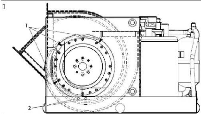
Mounting Eracket installation for B Cf H B a Cf H ACB + and Cf units
natural_image
Technical line drawing of a mechanical device with numbered components (no text or symbols present)) Mounting Eolt (not provided)
2 Yender Gasher provided
6 Mounting Eracket (provided)
Mounting Eracket installation for other air conditioning units
) Arain pan
2 Mounting Eracket
6 Mounting Colt Knot provided
EN
P. Install one mounting Eracket on each side of the drain pan even if spaced.
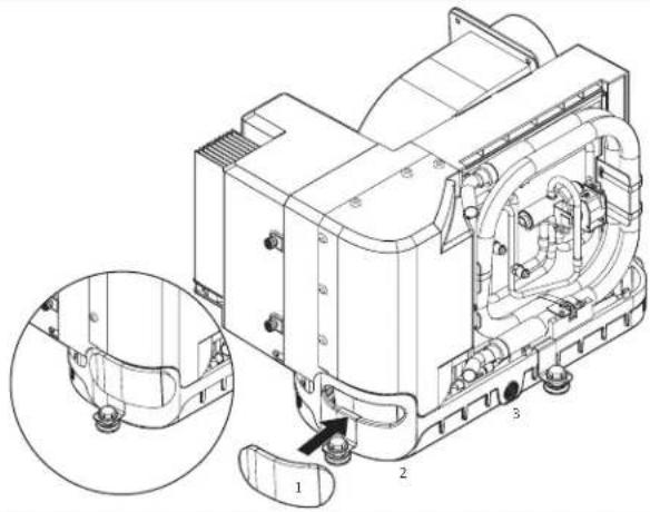
Installing Joam handle insulation on BaCf and Cf units
□
natural_image
Technical line drawing of a mechanical device with labeled parts (1, 2, 3), showing internal components and a magnified inset view (no text or symbols beyond labels)) Yoam handle insulation
2 e andle opening
6 Arain pan
Q. Yor Ba Cf and Cf units?
a) Remove the film covering the adhesive Eacking on the foam handle insulation.
E0 9osition the loam handle insulation to completelf cover the handle opening Gith the adhesive side facing the drain pan.
ci 9ress around the handle opening to adhere the loam handle insulation to the drain pan.
7/2 !nstalling t' e d01ting

. A N!NG- is3 of fire or explosion
AuLiliarF devices Ghich maF Ee ignition sources shall not Ee installed in the ductGorki other than auLiliarF devices listed for use Gith the specific appliance.
Yor models using flammaEle refrigerantsH Ghich are connected via an air duct sFstem to one or more roomsH the supplF and return air shall Ee directIF ducted to the space. h pen areas such as false ceilings shall not Ee used as a return air duct.
Ao not route ducting through an engine room or anF area Ghere it maF Ee eLposed to dangerous vapors or eLhaust lumes.
h Eserve the folloGing conditions Ghen installing the ducting?
[ Aucting must Ee appropriatelf sized for Four application.
[ Run ducting as straight smooth and taut as possiEle minimizing the numEer of TOI Eends and loops GHich can reduce airfloG.
[ Yasten the ducting secure] to prevent sagging.
[ Ao not alloG ducting to Ee flattened or kinked.
[ Crim eLcess ducting lengths JolloGing installation.
[ Insulate ducting Chen it is located in high-heat areas.
D a transition EoL is used the total area of supplF air ducts going out of the EoL should Ee at least equal to the total area of the supplF ducts going into the EoL. Refer to specifications on page 10
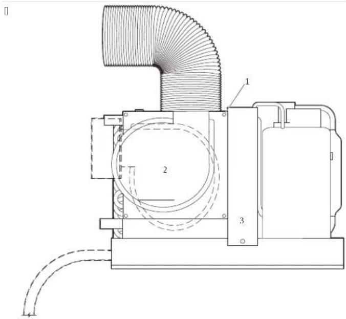
Aucting connections
□
natural_image
Pure mechanical diagram showing a coil and shaft assembly without any text, numbers, or symbols
natural_image
Pure technical line drawing of a mechanical component with no text or symbols) YiEerglass insulation 9 Inner mFlar duct hose
2 Mount ring: Auct tape
6 Transition EoL
J. Ilide the inner mFlar duct hose around the mount ring to the transition EoL.
- ! creG three or four stainless steel screGs through the mFlar duct hose into the mount ring† capturing tGo or three Gires Gith screG heads.
M. Ilide the 12 Eerglass insulation around the inner mFlar duct hose to the transition Eol. Iecure Gith duct tape.
7/6 !Installing t' e seawater system

NOT!CE-
Yailure to folloG this procedure Gill void the GarrantF.
h Eserve the JolloGing considerations Ghen setting up the seaGater sFstem?
[ Che strainer must Ee EeloG the pump.
[ oses must Ee douEle clamped.
[ e oses must not have kinksH loops- or high spots Ghere air can Ecome trapped.
[ Che pump and strainer must Ee EeloG the Gater line.
[ Che thru-hull inlet Eall valve- hose and strainer should Ee no smaller than the pump inlet.
[ Install the thru-hull 'tting as Jar EeloG the Gater line as possiEle.
[ Che pump must have a dedicated thru-hull.
[ Avoid T0.00 i elEoG "ttings as much as possiEle.
[ Knsure that the pump head is rotated toGard the direction of Gater floG.
[ Use plumEers tape on all threaded connections.
Refer to ! specifications on page 0 for maximum and minimum Gater temperature and pressure values.
!eaGater sFstem
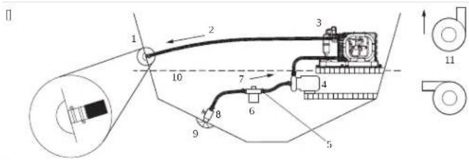
) !eaGater outlet 7 Uphill inlet floG
2 h utlet floG 8 l all valve
6 Air conditioner A ! coop thru-hull inlet
9 | eaGater pump )B V ater line
: e ose clamps )) ] orrect pump head strainer orientations
6! trainer
J. Install a seaGater scoop thru-hull inlet as close to the keel and as far EeloG the Gater line as possiEle. I secure the scoop thru-hull inlet using a marine-grade sealant designed for underGater use.
2. Install a Eronze+full-floG seacock on the seaGater scoop thru-hull inlet.
M. Install a seaGater strainer EeloG the level of the pump Gith access to the Witer.
4. Mount the pump aEove the strainer and at least one foot EeloG the Gaterline.
P. | onnect the seacock and strainer Gith an uphill run o) reinforced marine-grade hose.
Q.] onnect the discharge from the pump uphill to the Eottom inlet of the air conditioners condenser coil Gith a P/S in reinforced marine-grade hose.
R.] onnect the discharge from the condenser coil to the overBoard discharge thru-hull
Witting Gith a P/S in, reinforced marine-grade hose.
S. Avoid loops ^a high spots ^b or the use of T0i elEoGs Gith the seaGater hose. Kach T0i elEoG is equivalent to 2.P b 10.RQ m ^b o ^b hose and a T0i elEoG on the pump outlet is equivalent to 20.0 b 10.CJ 0 m ^b o ^b hose.
T. AouEle-clamp all hose connections using tGo stainless steel clamps reversing the clamps Ghere necessarF.
[0.] onnect all metallic parts in contact Gith seaGater to the vessels Eonding sFstem.
7/9 Ma3ing ele1trial 1onne1tions

. A N!NG- Ele1trials' o13 ' a5ard
AlGaFs turn od the air conditioning poGer supplF Breaker Eefore opening the electrical EoL. Yailure to oEeF this Gaining could result in death or serious injurF.
Knsure the electrical EoL is located in an area that is protected from Gater.

NOTICE-
Che air conditioner must Ee connected to the Eoats Eonding sFstem to prevent corrosion due to straF electrical current. All pumps: metallic valves and fittings in the seaGater circuit that are isolated from the air conditioner EF 9a] or ruEEer hoses: must Ee individually F Eonded to the Eoats Eonding sFstem.

NOTE Yailure to properIF ground and Eond the sFstem Gill void the GarrantF.
All conditioning units have a terminal strip[laEeled] for proper connections inside the electric EoL. Che Giring diagram inside the electric EoL supersedes Al X] standards. Use the correct size circuit Breaker to protect the sFstem as specified EF the air conditioning units data plate laEel. A minimum oJ 2 AV B Boat caEle should be used to suppIF poGer to the air conditioner and the seaGater pump. Make all connections using ring or captive fork terminals.
h Eserve the JolloGing Ghen making electrical connections?
[ Alternating current |A] 0 grounding must Ee connected to the ground terminal |B RNA at the A] poGer input terminal Elock.
[ ] oconnions EetGeen the vessels A] sFstem grounding conductor and the vessels direct current [A] 0 negative or Eonding sFstem should Ee made as part of the vessels Giring. V hen maintenance or replacing listing equipment that has a chassis-mounted ground stud check the vessels Giring for these connections.
[BaCf and Cf air conditioners are designed to operate on A] or high voltage A]. Refer to the vessels Giring diagram for correct placement.
Knsure that the A] ground of the air conditioner is properlF connected to the A] ground of the Boat. Within the Boat itself ensure that the A] ground Eus is connected to the A] ground Eus at elactlF one place.
] heck and retighten as necessarF all electrical connections prior to start up.
8 Disposal

CAUTION- Fire 'a5ard
This device contains flammaEle insulation EloGing gas.
h nIF have the device removed and disposed o) EF a specialist.

9 place the packaging material in the appropriate recFcling Gaste Eins² [Wherever possiEle.] onsult a local recFcling center or specialist dealer for details aEout hoG to dispose of the product in accordance Gith the applicaEle disposal regulations.
A Tel' nilal data
Read these instructions complete F and then plan the connections that must Ee made to the air conditioner (including ducting) condensate drain line seaGater inlet and outlet hoses electrical poGe connections location of the controlH and seaGater pump placement to assure easF access for routing and future maintenance.
A/) Part lolations
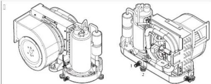
Air ] onditioning ! [Fstem ] component Identification
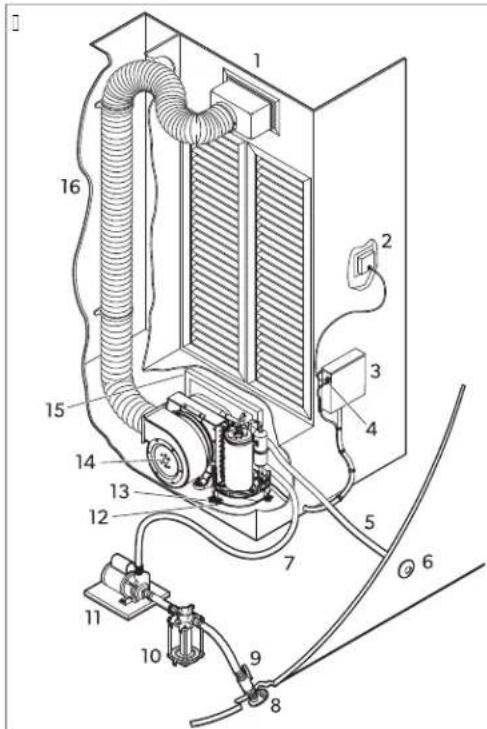
) UpplF air grille and transition EoL
A I eacock shut-od valve
2 Aigital displa
)B!eaGater strainer
EN( )
6 Klectric EoL)) 9ump
9 h p tional remote air sensor caEle )2 ] ondensate drain hose EarE
: |eaGater outlet hose)6 Mounting Eracket
6 h verEoard discharge)9 Air conditioner
7!eaGater inlet hose): Return air grille and filter
8 | eaGater scoop thru-hull inlet )6 Insulated JleLiEle ducting
A/2 Spelifilations
The refrigeration circuit contains a small quantitF of an environmentalIf FriendIf Eut flammaEle refrigerant. It does not damage the ozone laFer and does not increase the greenhouse effect. AnF leaking refrigerant maF ignite.
This product contains fluorinated greenhouse gases.
Che cooling unit is hermeticallF sealed.
Ta, le): Minim0m d01t and grille si5es per BTU 1apa1ity
| 6/: 3 BTU 6 3 BTU 8 3 BTU) B 3 BTU | ||||
| Minim0m d01t diameter | M.00 inMRG,2 mm ^2 | 4.00 inNJ 0J .Q mm ^2 | P.00 inNJ 2R.0 mm ^2 | Q.00 inNJ P2.4 mm ^2 |
| Minim0m d01t area | Q.S injMRW.T cmj ^2 | J 2.Q injKSJ .M cmj ^2 | J T.G injNJ 2G.P cmj ^2 | 2S.M injNJ S2.G cmj ^2 |
| Minim0m retOrn air grille | 4S.0 injMMOT.R cmj ^2 | Q4.0 injNJ 2.T cmj ^2 | S0.0 injWPJ G.2 cmj ^2 | J 00.0 injHG4P.2 cmj ^2 |
| Minim0ms0pply air grille | J 2.0 injMRR.4 cmj ^2 | M2.0 injN20Q.P cmj ^2 | 4S.0 injWMOT.R cmj ^2 | Q0.0 injMWSR.J cmj ^2 |
| ) 2 3 BTU ) 6 3 BTU ) 8 3 BTU 27 3 BTU | ||||
| Minim0m d01t diameter | Q.00 inNJ P2.4 mm ^2 | R.00 inNJ RR.S mm ^2 | R.00 inNJ RR.S mm ^2 | S.00 inN20M.2 mm ^2 |
| Minim0m d01t area | 25.M injNJ S2.Q cmj ^2 | MS.P injN24S.4 cmj ^2 | MS.P injN24S.4 cmj ^2 | P0.M injNW24.P cmj ^2 |
| Minim0m retOrn air grille | JM0.0 injHSMS.S cmj ^2 | J Q0.0 injNJ 0M2.M cmj ^2 | 200.0 injNJ 2T0.4 cmj ^2 | 240.0 injNJ P4S.P cmj ^2 |
| Minim0ms0pply air grille | R0.0 injI4PJ .Q cmj ^2 | S0.0 injWPJ Q.2 cmj ^2 | J 00.0 injVQ4P.2 cmj ^2 | J 20.0 injKRR4.2 cmj ^2 |
Ta, le 2: Operating water temperatOre and pressOre
| MinimOm operating water temperatOre 40.0i ¥14.44i ] 0 | |
| MaximOm operating water temperatOre 50.0i ¥120.00i ] 0 | |
| MinimOm operating water pressOre | 4.2 psi ¥0.2T Ear! ¥2T.00 k9a0 |
| MaximOm operating water pressOre | 0.00 psi ¥0.4| Ear! ¥4|.4 k9a0 |
YolloG K9A use conditions.

NOTE. Che unit can operate outside these conditions Gith reduced capacitF.
) B Legal
GVTX models only? Co complF Gith IK] QOPMMF do not mount the product Githin T.S b MM.00 m ^1 of a receiving antenna.
)) . arranty
Refer to the sections EeloG for information aEout GarrantF and GarrantF support in the U![] anada- and all other regions.
United States and Canada
UIMICKA V ARRANCX AaAllAl UK AC Ah MKCI] ] h M/KN-U! /CKRM! -ANA- ] h NAICIn N! -] h N! UMKR/V ARRANCX. IY Xh U e AaK k UK! CIh N! H h R Ch h I CAIN A] h 9X h Y Ce K UIMICKA V ARRANCX YRKK h Y] e ARB K- ] h NCA] G
DOMETIC CORPORATION
MARINE CUSTOMER SUPPORT CENTER
2000 NORTH ANDREWS AVENUE
POMPANO BEACH, FLORIDA, USA 33069
1-800-542-2477
Asia-Pa1ifi17APAC8 100ntries
If the product does not Cork as it should please contact Four retailer or the manufacturer's Eranch in Four countrF see dometic.com/dealer. The GarrantF applicaEle to Four product is J Fearls.
Yor repair and GarrantF processingH please include the JolloGing documents Ghen Fou send in the device?
[ A copF of the receipt Gith purchasing date
[ A reason for the claim or description of the fault
Note that self-repair or nonprofessional repair can have safety consequences and might void the GarrantF.
Australia Only
h ur goods come Gith guarantees that cannot Ee elcluded under the Australian ] onsumer UaG. You are entitled to a replacement or refund for a major failure and for compensation for anF other reasonaElf foreseeaEle loss or damage. You are also entitled to have the goods repaired or replaced if the goods fail to Ee of acceptaEle qualitF and the failure does not amount to a major failure.
New Cealand only
Chis GarrantF policF is suEject to the conditions and guarantees Ghich are mandatorF as implied EF the ] onsumer B guarantees Act JTTMNmC.
All ot' er regions
Che statutorF GarrantF period applies. To the product is defective please contact the manufacturer's Ercnch in Four countrF 'see dometic.com/dealer' or Four retailer.
Yor repair and GarrantF processingH please include the lolloGing documents Ghen Fou send in the device?
[ A copF o0 the receipt Gith purchasing date
[ A reason for the claim or description of the fault
Note that self-repair or nonprofessional repair can have safety consequences and might void the GarrantF.
De0ts1'
J V ichtige e inGeise....
[ American I oat and Xacht ] ouncil NAl X]
[AN! I/NY9A RO- National Electrical] ode INK]
2/2 Si1' er' eits' inweise

) 4+00 in 10J G cm³
9 WH00 in HR-G2 cm
2 AEluDtgitter : ! chott
6 Uitströmung
natural_image
Technical line drawing of a mechanical device with top and side views (no text or symbols))!creG
2 Uasche
6 BeEInse
natural_image
Technical line drawings of two mechanical components, one open and one closed, with no visible text or symbols.)!chlauchtplle (pr ' ondensataElau)
2 MontageEogel
) e ose EarE 9 Arain pan
) Uocking nut 9 ! olid Gasher
2 AElau!Ganne
: 9a] -Anschluss OHP in |J 2HR mmol E L OHP in |J 2HR mmol M9C0
6 AichtscheiEe
natural_image
Technical line drawing of a mechanical device with labeled components (no text or symbols present))! chaumsto@gri:-Isolierung
2 Briöchnung
6 AElau:Ganne
natural_image
Pure mechanical diagram showing a coil and housing assembly without any text, numbers, or symbols
natural_image
Pure technical line drawing of a mechanical component with no text or symbolsQ 9r"-installation....2]
R Installation....2M
J 0 Mentions 1" gales....2R
JJ B arantie....2R
[ American | oat and Xacht ] ouncil [Al X]
[ AN! I/NY9A R0- National Electrical ] ode [NK]
2/2 Consignes de sL10ritL

DANGE - isl 0e dllin1endie o0 dllexplosion/ Certains modNles Otilisent d0 rLfrigLrant inflamma, le/
) Adjustment screG
2 | loGer
)! creGs on EloGer ring
2 ! creGs on drain pan or Eracket
natural_image
Technical line drawings of two mechanical components, one showing internal components and the other a close-up view (no text or symbols)) Raccord cannel" de purge des condensats
2 | upport de montage
FR(
) e ose EarE 9 Arain pan
2 h rilice de purge filet : CuFau de purge
6 | ouchon d'entr" e d" conçaEle
) Docking nut 9 | olid Gasher
2 | ac de purge
: Raccord en 9a] 0HP in || 2HR mm0 e L 0HP in || 2HR mm0 M9C0
6 Rondelle dc 'tanch" it' liquide
) 1 oulon de filation non bournic
2 Rondelle plate HournieC
6 ! upport de montage Kourni?
) | ac de purge
2 : upport de montage
6 | oulon de Dilation non Dournic
natural_image
Technical line drawing of a mechanical device with labeled parts (1, 2, 3), showing internal components and a magnified inset view of a component detail (no text or symbols present)) Isolant de poign" e en mousse
2 h uverture de la poign' e
6 | ac de purge
natural_image
Pure mechanical diagram showing a coil and housing assembly without any text, numbers, or symbols
natural_image
Pure technical line drawing of a mechanical component with no text or symbols) 4:00 in 101Q cm ^2
9 NH00 in HR-C2 cm
2 Rejilla del aire de retorno : Mamparo
6 Ylujo de aire
)!creG
29laca
6 a entilador
natural_image
Technical line drawings of two mechanical components, one open and one closed, with no visible text or symbols.) Locking nut 9 ! olid Gasher
natural_image
Technical line drawing of a mechanical device with labeled parts (1, 2, 3), showing internal components and a magnified inset view of a component detail.natural_image
Pure mechanical diagram showing a coil and housing assembly without any text, numbers, or symbols
natural_image
Pure technical line drawing of a mechanical component with no text or symbols[ American | oat and Xacht ] ouncil | Al | X ]
[ AN! I/NY9A R0- National Electrical ] ode [NK]
) 4:00 in 10H Q cm³
9 NH00 in HR-C2 cm
2 B rade de ar de retorno : Antepara
6 YluLo de ar
) Adjustment screG
2 | loGer
natural_image
Technical line drawings of two mechanical components, one open and one closed, with no visible text or symbols.) Close EarE 9 Arain pan
PT(11)
) Uocking nut 9 ! olid Gasher
natural_image
Technical line drawing of a mechanical device with labeled parts (1, 2, 3), showing internal components and a magnified inset view of a component detail (no text or symbols present)natural_image
Pure mechanical diagram showing a coil and housing assembly without any text, numbers, or symbols
natural_image
Pure technical line drawing of a mechanical component with no text or symbolsA/) Lo1ali5ajões das pej as
[ American I oat and Xacht ] council |AI | X]
[AN! I/NY9A R0- National Electrical ] ode [NK]
2/2 !str05ioni per la si10re55a

natural_image
Technical line drawings of two mechanical components, one showing internal components and the other with internal structure (no text or symbols)) close EarE 9 Arain pan
) Uocking nut 9 ! olid Gasher
natural_image
Technical line drawing of a mechanical device with labeled parts (1, 2, 3), showing internal components and a magnified inset view of a component detail.) 4+00 in 10J G cm³
9 WH00 in HR-G2 cm
2 A:voerlucht-rooster : ! chutEord
6 Uuchtstroom
natural_image
Technical line drawing of a mechanical device with top and side views (no text or symbols)) Adjustment screG
2 | loGer
)!creG
2 | ord
6 a entilator
natural_image
Technical line drawings of two mechanical components, one open and one closed, with no visible text or symbols.) Uocking nut 9 ! olid Gasher
2 AivoerEak
: 9a | -Citting OHP in || 2HR mm0 c | L OHP in || 2HR mm0 M9Cl
6 aloeistol-a-dichtring
J. aoor units B Cf H Ba Cf H ACB en Cf units?
natural_image
Technical line drawing of a mechanical assembly with numbered components (no text or symbols)natural_image
Technical line drawing of a mechanical device with labeled components (no text or symbols present)) ! chuimgreepisolatie
2 e andgreepopening
6 AvoerEak
Q. aoor units BaCf en Cf?
natural_image
Pure mechanical diagram showing a coil and housing assembly without any text, numbers, or symbols
natural_image
Pure technical line drawing of a mechanical component with no text or symbols) Blasvezelisolatie 9 MFlar EinnenEuisslang
2 Montagering: Auct tape
6 h vergangsdoos
[ American | oat and Xacht ] ouncil NAI X]
[ AN! I/NY9A R0- National Electrical ] ode [NK] 0
2/2 Si33er' eds' en2isninger

FA E- isi3o for, rand eller e3splosion/ Nogle modeller an2ender, rb nd, art 3clemiddel/
ADVA SEL- Fare for ele3tris3 stcd
) 4+00 in 10J Q cm
9 WH00 in HR-C2 cm
2 Returluftgitter : ! kot
6 Uitström
DA
)!creG
2 Uaske
6 | læser
natural_image
Technical line drawings of two mechanical components, one open and one closed, with no visible text or symbols.) close EarE 9 Arain pan
2 AlloEshul med gevind : AlloEsslange
6 Udslagshul
) Locking nut 9 ! olid Gasher
2 AltapningsEakke
: 9a] -Eeslag 0HP in 2HR mmC e L 0HP in 2HR mmO M90
6 Cætningsskive
J. Yor B Cf - H Ba Cf - H ACB - og Cf -enheder?
) AltapningsEakke
2 MonteringsEeslag
6 MonteringsEolt medølger ikke:
DA
natural_image
Technical line drawing of a mechanical device with labeled components (no text or symbols present)) ! kumhändtagsisolering
2 e åndtagsåEning
6 AltapningsEakke
natural_image
Pure mechanical diagram showing a coil and housing assembly without any text, numbers, or symbols
natural_image
Pure technical line drawing of a mechanical component with no text or symbols) BlasiiEerisolering 9 Indvendig kanalslange a:mFlar
FO S!GT!G- Brandfare
A/) Delenes pla1ering
[ American I oat and Xacht ] ouncil NAI X]
[ AN! I/NY9A RO- National Electrical ] ode NNK]
2/2 SD3er' etsan2isningar

FA A- is3 fHr, rand eller explosion/ Vissa modeller an2Dnder lDttantDndligt 3ylmedel/
aarning | randrisk/ErnnnEara material

Refrigerant Safety Group A2L
) 4+00 in 10J G cm³
9 WH00 in HR-G2 cm
2 Yrånluftsgaller : ! kott
6 Uutlqde
)!creG
2!kFlt
6 Yinkt
natural_image
Technical line drawings of two mechanical components, one with internal components and the other showing internal structure (no text or symbols)) ! langnippel till kondensatavlopp
2 Monteringsløste
) e ose EarE 9 Arain pan
) Docking nut 9 | olid Gasher
2 AvloppsEehållare
: 9a] -anslutning 0HP in 12-R mmol L 0HP in 12-R mmol M90
SV(111)
6 CtningsEricka
J. Yqr B Cf -H B a Cf -H ACB -och Cf -enheter?
natural_image
Technical line drawing of a mechanical device with numbered components (no text or symbols present)) MonteringsEult hmed:qljer ej
2 | tnnkskFddsEricka :medqljer0
6 Monteringsrste medioljer
natural_image
Technical line drawing of a mechanical device with labeled parts (1, 2, 3), showing internal components and a magnified inset view of a component detail.natural_image
Pure mechanical diagram showing a coil and housing assembly without any text, numbers, or symbols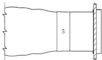
natural_image
Pure technical line drawing of a mechanical component with no text or symbols) BlasliEerisolering 9 Inre slangqr av MFlar
2 Monteringsring : Cejp
6 s vergångslåda
ADVA SEL-Fare for ele3tris3 stct
ADVA SEL- Fare for ele3tris3 stct, , rann og4eller e3splos/on
ADVA SEL-Fare for ele3tris3 stct
) 4+00 in 10J G cm³
9 WH00 in HR-G2 cm
2 Bitter for utElåsningslu:t : ! kott
6 Uitström
natural_image
Technical line drawing of a mechanical device with top and side views (no text or symbols))!creG
2'lad
6 ailte
ADVA SEL- Fare for ele3tris3 stct
natural_image
Technical line drawings of two mechanical components, one open and one closed, with no visible text or symbols.) Yeste for kondensavtappingsledning
2 MonteringsErakett
) e ose EarE 9 Arain pan
2 B jenget avtappingshall : Avtappingsslange
6 9lugg som kan slås ut
NB
) Ucking nut 9 ! olid Gasher
2 AvtappingsErett
: 9a] -rørdel 0P in |j 2HR mm ^1 e | L 0P in |j 2HR mm ^1 M9Cl
natural_image
Technical line drawing of a mechanical device with numbered components (no text or symbols)natural_image
Technical line drawing of a mechanical device with labeled components (no text or symbols present)natural_image
Pure mechanical diagram showing a coil and housing assembly without any text, numbers, or symbols
natural_image
Pure technical line drawing of a mechanical component with no text or symbols) BlassliEerisolering 9 Indre mFlarrørslange
2 Yestering : Industritape
6 Inntaksskap
ADVA SEL-Fare for ele3tris3 stct
I lå alltid av sikringen til klimaanlegget før du Eetjener koElingsEoksen. Manglende overholdelse av denne adverselen kan resultere i alvorlige personskader eventuelt med døden til følge.
!org for at koElingsEoksen er plassert på et sted der den er EeskFttet mot vann.

PASS Pf -
Gelder 30n for Australia
Gelder 30n for New Zealand
Aenne garantien underligger vilkårene og garantiEestemmelsene i JorErukergarantiloven ] onsumer B guarantees Act JTTMNm ^1 .
Alle andre regioner
Lovmessig garantitid gjelder. e vis produktet er dejekt? Ca kontakt med produsentens Wial Use dometic.com/dealer? eller Dorhandler i ditt land.
[ American I oat and Xacht ] council NAI X]
[ AN! I/NY9A R0- National Electrical ] ode [NK] 0
2/2 T0r2allis00so' Veet

VAA A- Palo- tai rDVD' dys2aara/ eoissa3in malleissa 3DytetDDn sytty2DD 3ylmDainetta/


- Copyright t
- Englis'
- ) !important notes
- Explanation of sym, ols
- 2/) S0ppplemental dire1ti2es
- 2/2 Safety instr01tions
- EN[1]
- Target gro0p7s8
- !Intended 0se
- : Explanation of sym, ols on t' e de2i1e
- Pre-installation
- 6/) Determining t' e installation lo1ation
- 6/2 otating t' e, lower
- 6/2/) GTX, GVTX, DTG, and TX, lowers
- EN
- !Installation
- 7/2 !nstalling t' e d01ting
- 7/6 !Installing t' e seawater system
- 7/9 Ma3ing ele1trial 1onne1tions
- Disposal
- A Tel' nilal data
- A/) Part lolations
- EN( )
- A/2 Spelifilations
- ) B Legal
- )) . arranty
- United States and Canada
- Asia-Pa1ifi17APAC8 100ntries
- Australia Only
- New Cealand only
- All ot' er regions
- De0ts1'
- 2/2 Si1' er' eits' inweise
- 2/2 Consignes de sL10ritL
- FR(
- PT(11)
- A/) Lo1ali5ajões das pej as
- 2/2 !str05ioni per la si10re55a
- 2/2 Si33er' eds' en2isninger
- DA
- Cætningsskive
- A/) Delenes pla1ering
- 2/2 SD3er' etsan2isningar
- SV(111)
- CtningsEricka
- ADVA SEL-Fare for ele3tris3 stct
- NB
- PASS Pf -
- Gelder 30n for Australia
- Gelder 30n for New Zealand
- Alle andre regioner
- 2/2 T0r2allis00so' Veet
Brand : DOMETIC
Model : DCU
Category : Air Conditioning