Q270 Pro BTC+ - Motherboard ASROCK - Free user manual and instructions
Find the device manual for free Q270 Pro BTC+ ASROCK in PDF.
Download the instructions for your Motherboard in PDF format for free! Find your manual Q270 Pro BTC+ - ASROCK and take your electronic device back in hand. On this page are published all the documents necessary for the use of your device. Q270 Pro BTC+ by ASROCK.
USER MANUAL Q270 Pro BTC+ ASROCK
Version 1.0 Published June 2021 Copyright©2021 ASRock INC. All rights reserved. Copyright Notice: No part of this documentation may be reproduced, transcribed, transmitted, or translated in any language, in any form or by any means, except duplication of documentation by the purchaser for backup purpose, without written consent of ASRock Inc. Products and corporate names appearing in this documentation may or may not be registered trademarks or copyrights of their respective companies, and are used only for identication or explanation and to the owners’ benet, without intent to infringe. Disclaimer: Specications and information contained in this documentation are furnished for informational use only and subject to change without notice, and should not be constructed as a commitment by ASRock. ASRock assumes no responsibility for any errors or omissions that may appear in this documentation. With respect to the contents of this documentation, ASRock does not provide warranty of any kind, either expressed or implied, including but not limited to the implied warranties or conditions of merchantability or tness for a particular purpose. In no event shall ASRock, its directors, ocers, employees, or agents be liable for any indirect, special, incidental, or consequential damages (including damages for loss of prots, loss of business, loss of data, interruption of business and the like), even if ASRock has been advised of the possibility of such damages arising from any defect or error in the documentation or product. is device complies with Part 15 of the FCC Rules. Operation is subject to the following two conditions: (1) this device may not cause harmful interference, and (2) this device must accept any interference received, including interference that may cause undesired operation.
CALIFORNIA, USA ONLY
e Lithium battery adopted on this motherboard contains Perchlorate, a toxic substance controlled in Perchlorate Best Management Practices (BMP) regulations passed by the California Legislature. When you discard the Lithium battery in California, USA, please follow the related regulations in advance. “Perchlorate Material-special handling may apply, see www.dtsc.ca.gov/hazardouswaste/ perchlorate” ASRock Website: http://www.asrock.comAUSTRALIA ONLY Our goods come with guarantees that cannot be excluded under the Australian Consumer Law. You are entitled to a replacement or refund for a major failure and compensation for any other reasonably foreseeable loss or damage caused by our goods. You are also entitled to have the goods repaired or replaced if the goods fail to be of acceptable quality and the failure does not amount to a major failure. If you require assistance please call ASRock Tel : +886-2-28965588 ext.123 (Standard International call charges apply) e terms HDMI® and HDMI High-Denition Multimedia Interface, and the HDMI logo are trademarks or registered trademarks of HDMI Licensing LLC in the United States and other countries.
INTEL END USER SOFTWARE LICENSE AGREEMENT
IMPORTANT - READ BEFORE COPYING, INSTALLING OR USING. LICENSE. Licensee has a license under Intel’s copyrights to reproduce Intel’s Soware only in its unmodied and binary form, (with the accompanying documentation, the “Soware”) for Licensee’s personal use only, and not commercial use, in connection with Intel-based products for which the Soware has been provided, subject to the following conditions: (a) Licensee may not disclose, distribute or transfer any part of the Soware, and You agree to prevent unauthorized copying of the Soware. (b) Licensee may not reverse engineer, decompile, or disassemble the Soware. (c) Licensee may not sublicense the Soware. (d) e Soware may contain the soware and other intellectual property of third party suppliers, some of which may be identied in, and licensed in accordance with, an enclosed license.txt le or other text or le. (e) Intel has no obligation to provide any support, technical assistance or updates for the Soware. OWNERSHIP OF SOFTWARE AND COPYRIGHTS. Title to all copies of the Soware remains with Intel or its licensors or suppliers. e Soware is copyrighted and protected by the laws of the United States and other countries, and international treaty provisions. Licensee may not remove any copyright notices from the Soware. Except as otherwise expressly provided above, Intel grants no express or implied right under Intel patents, copyrights, trademarks, or other intellectual property rights. Transfer of the license termi- nates Licensee’s right to use the Soware. DISCLAIMER OF WARRANTY. e Soware is provided “AS IS” without warranty of any kind, EITHER EXPRESS OR IMPLIED, INCLUDING WITHOUT LIMITATION, WARRANTIES OF MERCHANTABILITY OR FITNESS FOR ANY PARTICULAR PUR- POSE. LIMITATION OF LIABILITY. NEITHER INTEL NOR ITS LICENSORS OR SUPPLIERS WILL BE LIABLE FOR ANY LOSS OF PROFITS, LOSS OF USE, INTERRUPTION OF BUSINESS, OR INDIRECT, SPECIAL, INCIDENTAL, OR CONSEQUENTIAL DAMAG-DAMAGES OF ANY KIND WHETHER UNDER THIS AGREEMENT OR OTHERWISE, EVEN IF INTEL HAS BEEN ADVISED OF THE POSSIBILITY OF SUCH DAMAGES. LICENSE TO USE COMMENTS AND SUGGESTIONS. is Agreement does NOT obligate Licensee to provide Intel with comments or suggestions regarding the Soware. However, if Licensee provides Intel with comments or suggestions for the modication, correction, improvement or enhancement of (a) the Soware or (b) Intel products or processes that work with the Soware, Licensee grants to Intel a non-exclusive, worldwide, perpetual, irrevocable, transferable, royalty-free license, with the right to sublicense, under Licensee’s intellectual property rights, to incorporate or otherwise utilize those comments and suggestions. TERMINATION OF THIS LICENSE. Intel or the sublicensor may terminate this license at any time if Licensee is in breach of any of its terms or conditions. Upon termination, Licensee will immediately destroy or return to Intel all copies of the Soware. THIRD PARTY BENEFICIARY. Intel is an intended beneciary of the End User License Agreement and has the right to enforce all of its terms. U.S. GOVERNMENT RESTRICTED RIGHTS. e Soware is a commercial item (as dened in 48 C.F.R. 2.101) consisting of commercial computer soware and commercial computer soware documentation (as those terms are used in 48 C.F.R. 12.212), consistent with 48 C.F.R. 12.212 and 48 C.F.R 227.7202-1 through 227.7202-4. You will not provide the Soware to the U.S. Government. Contractor or Manufacturer is Intel Corporation, 2200 Mission College Blvd., Santa Clara, CA 95054. EXPORT LAWS. Licensee agrees that neither Licensee nor Licensee’s subsidiaries will export/re-export the Soware, directly or indirectly, to any country for which the U.S. Department of Commerce or any other agency or department of the U.S. Government or the foreign government from where it is shipping requires an export license, or other governmental approval, without rst obtaining any such required license or approval. In the event the Soware is exported from the U.S.A. or re-exported from a foreign destina- tion by Licensee, Licensee will ensure that the distribution and export/re-export or import of the Soware complies with all laws, regulations, orders, or other restrictions of the U.S. Export Administration Regulations and the appropriate foreign government. APPLICABLE LAWS. is Agreement and any dispute arising out of or relating to it will be governed by the laws of the U.S.A. and Delaware, without regard to conict of laws principles. e Parties to this Agreement exclude the application of the United Nations Convention on Contracts for the International Sale of Goods (1980). e state and federal courts sitting in Delaware, U.S.A. will have exclusive jurisdiction over any dispute arising out of or relating to this Agreement. e Parties consent to personal jurisdiction and venue in those courts. A Party that obtains a judgment against the other Party in the courts identied in this section may enforce that judgment in any court that has jurisdiction over the Parties. Licensee’s specic rights may vary from country to country.English
- ere are two LEDs on the LAN port. Please refer to the table below for the LAN port LED indications. Activity / Link LED Speed LED Status Description Status Description O No Link O 10Mbps connection Blinking Data Activity Orange 100Mbps connection On Link Green 1Gbps connection ACT/LINK LEDSPEED LEDLAN Port
** Function of the Audio Ports in 7.1-channel Conguration: Port Function Light Blue (Rear panel) Rear Speaker Out Lime (Rear panel) Front Speaker Out Pink (Rear panel) Central /Subwoofer Speaker Out Lime (Front panel) Side Speaker OutEnglish
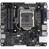
ank you for purchasing ASRock Q270 Pro BTC+ motherboard, a reliable motherboard produced under ASRock’s consistently stringent quality control. It delivers excellent performance with robust design conforming to ASRock’s commitment to quality and endurance.
1 x I/O Panel Shield Because the motherboard specications and the BIOS soware might be updated, the content of this documentation will be subject to change without notice. In case any modications of this documentation occur, the updated version will be available on ASRock’s website without further notice. If you require technical support related to this motherboard, please visit our website for specic information about the model you are using. You may nd the latest VGA cards and CPU support list on ASRock’s website as well. ASRock website http://www.asrock.com.English
Solid Capacitor design CPU
Supports CPU up to 91W
6 Power Phase design
Supports Intel® Turbo Boost 2.0 Technology Chipset
Supports Intel® Active Management Technology 11.6
Technology and Intel® Active Management Technology 11.6 can be supported only with Intel® Core
processor family Memory
Dual Channel DDR4 Memory Technology
Gen Intel® CPU supports DDR4 up to 2400; 6
Gen Intel® CPU supports DDR4 up to 2133.
Supports ECC UDIMM memory modules (operate in non- ECC mode)
Max. capacity of system memory: 32GB
Supports Intel® Extreme Memory Prole (XMP) 2.0
- Supports NVMe SSD as boot disks
Intel® HD Graphics Built-in Visuals and the VGA outputs can be supported only with processors which are GPU integrated.
Supports HDMI 1.4 with max. resolution up to 4K x 2K (4096x2160) @ 24Hz / (3840x2160) @ 30HzEnglish
Supports Auto Lip Sync, Deep Color (12bpc), xvYCC and HBR (High Bit Rate Audio) with HDMI 1.4 Port (Compliant HDMI monitor is required)
Supports HDCP 1.4 with HDMI 1.4 Port
Supports Full HD 1080p Blu-ray (BD) playback with HDMI
Supports Surge Protection LAN
Supports Wake-On-LAN
Supports Lightning/ESD Protection
Supports Energy Ecient Ethernet 802.3az
Supports PXE Rear Panel I/O
4 x USB 2.0 Ports (Supports ESD Protection)
2 x USB 3.2 Gen1 Ports (Supports ESD Protection)
1 x RJ-45 LAN Port with LED (ACT/LINK LED and SPEED LED)
HD Audio Jacks: Line in / Front Speaker / Microphone Storage
Supports RAID 0, RAID 1, RAID 5 and RAID 10 for SATA storage devices Connector
1 x CPU Fan Connector (4-pin)
- e CPU Fan Connector supports the CPU fan of maximum 1A (12W) fan power.
1 x Front Panel Audio Connector
1 x USB 2.0 Header (Supports 2 USB 2.0 ports) (Supports ESD Protection)
1 x USB 3.2 Gen1 Header (Supports 2 USB 3.2 Gen1 ports) (Supports ESD Protection)
AMI UEFI Legal BIOS with multilingual GUI support
ACPI 6.0 Compliant wake up events
CPU/Chassis Quiet Fan (Auto adjust chassis fan speed by CPU temperature)
CPU/Chassis Fan multi-speed control
- To install Windows® 7 OS, a modied installation disk with xHCI drivers packed into the ISO le is required. Please refer to page 28 for more detailed instructions.
ErP/EuP Ready (ErP/EuP ready power supply is required) Please realize that there is a certain risk involved with overclocking, including adjusting the setting in the BIOS, applying Untied Overclocking Technology, or using third-party overclocking tools. Overclocking may aect your system’s stability, or even cause damage to the components and devices of your system. It should be done at your own risk and expense. We are not responsible for possible damage caused by overclocking.
- For detailed product information, please visit our website: http://www.asrock.comEnglish
Q270 Pro BTC+ is is an ATX form factor motherboard. Before you install the motherboard, study the conguration of your chassis to ensure that the motherboard ts into it. Pre-installation Precautions Take note of the following precautions before you install motherboard components or change any motherboard settings.
Make sure to unplug the power cord before installing or removing the motherboard components. Failure to do so may cause physical injuries and damages to motherboard components.
In order to avoid damage from static electricity to the motherboard’s components, NEVER place your motherboard directly on a carpet. Also remember to use a grounded wrist strap or touch a safety grounded object before you handle the components.
Hold components by the edges and do not touch the ICs.
Whenever you uninstall any components, place them on a grounded anti-static pad or in the bag that comes with the components.
When placing screws to secure the motherboard to the chassis, please do not over- tighten the screws! Doing so may damage the motherboard.
2.1 Installing the CPU
1. Before you insert the 1151-Pin CPU into the socket, please check if the PnP cap
is on the socket, if the CPU surface is unclean, or if there are any bent pins in the socket. Do not force to insert the CPU into the socket if above situation is found. Otherwise, the CPU will be seriously damaged.
Please save and replace the cover if the processor is removed. e cover must be placed if you wish to return the motherboard for aer service.English
2.2 Installing the CPU Fan and Heatsink
is motherboard provides two 288-pin DDR4 (Double Data Rate 4) DIMM slots, and supports Dual Channel Memory Technology. e DIMM only ts in one correct orientation. It will cause permanent damage to the motherboard and the DIMM if you force the DIMM into the slot at incorrect orientation.
1. For dual channel conguration, you always need to install identical (the same
brand, speed, size and chip-type) DDR4 DIMM pairs.
2. It is unable to activate Dual Channel Memory Technology with only one memory
3. It is not allowed to install a DDR, DDR2 or DDR3 memory module into a DDR4
slot; otherwise, this motherboard and DIMM may be damaged.English
ere are 13 PCI Express slots on the motherboard. PCIe slots: PCIE2 (PCIe 3.0 x16 slot) is used for PCI Express x16 lane width graphics cards. PCIE1_1/PCIE1/PCIE2_1/PCIE3_1/PCIE3/PCIE4_1/PCIE4/PCIE5_1/PCIE5/ PCIE6_1/PCIE6/PCIE7_1 (PCIe 3.0 x1 slot) is used for PCI Express x1 lane width graphics cards. Before installing an expansion card, please make sure that the power supply is switched o or the power cord is unplugged. Please read the documentation of the expansion card and make necessary hardware settings for the card before you start the installation.
1. Please connect the SATA power connector and PCIe power connectors to the power
supply when three graphics cards are installed on this motherboard.
2. 12V power supply can only provide 1.2A current in the white PCIe slots.English
e illustration shows how jumpers are setup. When the jumper cap is placed on the pins, the jumper is “Short”. If no jumper cap is placed on the pins, the jumper is “Open”. Clear CMOS Jumper (CLRMOS1) (see p.1, No. 12) CLRMOS1 allows you to clear the data in CMOS. To clear and reset the system parameters to default setup, please turn o the computer and unplug the power cord from the power supply. Aer waiting for 15 seconds, use a jumper cap to short the pins on CLRMOS1 for 5 seconds. However, please do not clear the CMOS right aer you update the BIOS. If you need to clear the CMOS when you just nish updating the BIOS, you must boot up the system rst, and then shut it down before you do the clear-CMOS action. Please be noted that the password, date, time, and user default prole will be cleared only if the CMOS battery is removed. Please remember toremove the jumper cap aer clearing the CMOS. 2-pin Jumper If you clear the CMOS, the case open may be detected. Please adjust the BIOS option “Clear Status” to clear the record of previous chassis intrusion status.English
2.6 Onboard Headers and Connectors
System Panel Header (9-pin PANEL1) (see p.1, No. 10) Connect the power switch, reset switch and system status indicator on the chassis to this header according to the pin assignments below. Note the positive and negative pins before connecting the cables. Chassis Intrusion and Speaker Header (7-pin SPK_CI1) (see p.1, No. 11) Please connect the chassis intrusion and the chassis speaker to this header. PWRBTN (Power Switch): Connect to the power switch on the chassis front panel. You may congure the way to turn o your system using the power switch. RESET (Reset Switch): Connect to the reset switch on the chassis front panel. Press the reset switch to restart the computer if the computer freezes and fails to perform a normal restart. PLED (System Power LED): Connect to the power status indicator on the chassis front panel. e LED is on when the system is operating. e LED keeps blinking when the system is in S1/S3 sleep state. e LED is o when the system is in S4 sleep state or powered o (S5). HDLED (Hard Drive Activity LED): Connect to the hard drive activity LED on the chassis front panel. e LED is on when the hard drive is reading or writing data. e front panel design may dier by chassis. A front panel module mainly consists of power switch, reset switch, power LED, hard drive activity LED, speaker and etc. When connecting your chassis front panel module to this header, make sure the wire assignments and the pin assignments are matched correctly. Onboard headers and connectors are NOT jumpers. Do NOT place jumper caps over these headers and connectors. Placing jumper caps over the headers and connectors will cause permanent damage to the motherboard. GN D R E S ET#P W R BTN#P L E D-P L E D+ GN D H D L ED-H D L ED+
Q270 Pro BTC+ Serial ATA3 Connectors Right Angle: (SATA3_0: see p.1, No. 8) (Upper) (SATA3_1: see p.1, No. 8) (Lower) (SATA3_2: see p.1, No. 9) (Upper) (SATA3_3: see p.1, No. 9) (Lower) ese four SATA3 connectors support SATA data cables for internal storage devices with up to
6.0 Gb/s data transfer rate.
SATA Power Connector (SATA_POW1) (see p.1, No. 17) Please connect this connector to the power supply when three graphics cards are installed on this motherboard. USB 2.0 Header (9-pin USB_5_6) (see p.1, No. 14) ere is one header on this motherboard. is USB 2.0 header can support two ports. USB 3.2 Gen1 Header (19-pin USB3_3_4) (see p.1, No. 13) ere is one header on this motherboard. is USB 3.2 Gen1 header can support two ports. DUMMY GND GND
Front Panel Audio Header (9-pin HD_AUDIO1) (see p.1, No. 19) is header is for connecting audio devices to the front audio panel. Chassis Fan Connectors (4-pin CHA_FAN1) (see p.1, No. 7) (4-pin CHA_FAN2) (see p.1, No. 20) Please connect fan cables to the fan connector and match the black wire to the ground pin. CPU Fan Connector (4-pin CPU_FAN1) (see p.1, No. 2) is motherboard pro- vides a 4-Pin CPU fan (Quiet Fan) connector. If you plan to connect a 3-Pin CPU fan, please connect it to Pin 1-3.
1. High Denition Audio supports Jack Sensing, but the panel wire on the chassis
must support HDA to function correctly. Please follow the instructions in our manual and chassis manual to install your system.
2. If you use an AC’97 audio panel, please install it to the front panel audio header by
the steps below: A. Connect Mic_IN (MIC) to MIC2_L. B. Connect Audio_R (RIN) to OUT2_R and Audio_L (LIN) to OUT2_L. C. Connect Ground (GND) to Ground (GND). D. MIC_RET and OUT_RET are for the HD audio panel only. You don’t need to connect them for the AC’97 audio panel. E. To activate the front mic, go to the “FrontMic” Tab in the Realtek Control panel and adjust “Recording Volume”.
Q270 Pro BTC+ ATX Power Connector (24-pin ATXPWR1) (see p.1, No. 6) is motherboard pro- vides a 24-pin ATX power connector. To use a 20-pin ATX power supply, please plug it along Pin 1 and Pin
ATX 12V Power Connector (8-pin ATX12V1) (see p.1, No. 1) is motherboard pro- vides an 8-pin ATX 12V power connector. To use a 4-pin ATX power supply, please plug it along Pin 1 and Pin 5. PCIe Power Connectors (4-pin PCIE_PWR1) (see p.1, No. 21) (4-pin PCIE_PWR2) (see p.1, No. 18) Please connect these connectors to the power supply when three graphics cards are installed on this motherboard. Please refer to page 23 for PCIe Power Connector Installation Guide. Serial Port Header (9-pin COM1) (see p.1, No. 16) is COM1 header supports a serial port module. TPM Header (17-pin TPMS1) (see p.1, No. 15) is connector supports Trusted Platform Module (TPM) system, which can securely store keys, digital certicates, passwords, and data. A TPM system also helps enhance network security, protects digital identities, and ensures platform integrity.
P CICL KP CIRST #LA D3
e motherboard has two smart buttons: Power Button and Reset Button. Power Button (PWRBTN1) (see p.1, No. 4) Power Button allows users to quickly turn on/o the system. Reset Button (RSTBTN1) (see p.1, No. 5) Reset Button allows users to quickly reset the system.English
e two extra 4-pin power connectors on this motherboard oer more power for your graph-ics cards. ey provide stable voltages and greatly reduce the risks of burning your mother-board or graphics cards. When more than three graphics cards are installed, be sure to install the PSU’s 4-pin power cables to the 4-pin power connectors (PCIE_PWR) on your motherboard; otherwise, the cards may be damaged. Please MUST install TWO PSU’s 4-pin power cables to your MB’s TWO 4-pin power connectors. Plug one of the PSU's 4-pin power connector ( ) to the 4-pin power connector closer to the PCIe x16 slot ( PCIE_PWR1) . en plug another PSU's 4-pin power connector ( ) to the other 4-pin power connector ( PCIE_PWR2) . If your PSU only provides ONE, then please MUST install it to the 4-pin power connector (PCIE_ PWR1) closer to the PCIe x16 slot. Important: Besides the two PCIe power connectors, please connect the SATA power connector as well when you install more then three graphics cards. Make sure all the connected power connectors (4-pin, 24-pin and SATA) are on the same PSU; otherwise, the motherboard may be damaged. *e diagrams shown here are for reference only. Please refer to the user manual that comes with your motherboard for the accurate location of the 4-pin power connectors.
The M.2, also known as the Next Generation Form Factor (NGFF), is a small size and versatile card edge connector that aims to replace mPCIe and mSATA. e M.2 Socket (M2_1) supports type 2260/2280 M.2 SATA3 6.0 Gb/s module. Installing the M.2_SSD (NGFF) Module Step 1 Prepare a M.2_SSD (NGFF) module and the screw. Step 2 Depending on the PCB type and length of your M.2_SSD (NGFF) module, nd the corresponding nut location to be used. No. 1 2 Nut Location A B PCB Length 6cm 8cm Module Type Type2260 Type 2280English
Q270 Pro BTC+ Step 3 Move the stando based on the module type and length. e stando is placed at the nut location B by default. Skip Step 3 and 4 and go straight to Step 5 if you are going to use the default nut. Otherwise, release the stando by hand. Step 4 Peel o the yellow protective lm on the nut to be used. Hand tighten the stando into the desired nut location on the motherboard. Step 5 Gently insert the M.2 (NGFF) SSD module into the M.2 slot. Please be aware that the M.2 (NGFF) SSD module only ts in one orientation. Step 6 Tighten the screw with a screwdriver to secure the module into place. Please do not overtighten the screw as this might damage the module.
is motherboard has included a smart way to show the status of every graphics card. While the system is booting, the Power-On, Self-Test (POST) screen will show the status of the graphics cards that were installed on the motherboard.English
Intel® new processors have removed their support for the Enhanced Host Controller Interface (EHCI – USB2.0) and only kept the eXtensible Host Controller Interface (XHCI – USB3.0). Due to that fact that XHCI is not included in the Windows 7 inbox drivers, users may nd it dicult to install Windows 7 operating system because the USB ports on their motherboard won’t work. In order for the USB ports to function properly, please create a Windows® 7 installation disk with the Intel® USB 3.2 Gen1 eXtensible Host Controller (xHCI) drivers packed into the ISO le. Requirements
Win7 USB Patcher (included in the ASRock Support CD or downloaded from website) Scenarios You have an ODD and PS/2 ports: If there is an optical disc drive, PS/2 ports and PS/2 Keyboard or mouse on your computer, you can skip the instructions below and go ahead to install Windows® 7 OS. You’ve got nothing: If you do not have an optical disc drive, please nd another computer and follow the instructions below to create a new ISO le with the “Win7 USB Patcher”. en use the new patched Windows® 7 installation USB drive to install Windows® 7 OS.English
Q270 Pro BTC+ Instructions Step 1 Insert the Windows® 7 installation disk or USB drive to your system. Step 2 Extract the tool (Win7 USB Patcher) and launch it. Step 3 Select how you want to install Windows 7 later. Step 4 Locate your Win7 source folder or your ISO le.English
CC T S#1RR TS#1DD S R#1DD T R#1RR X D1 GN D TT X D1DD C D#1 RR I #1
GN D SM B _DATA_MAI NLA D 2LA D 1 GN D
S_ P WRDWN #SE R IRQ #
CC TS#1RR TS #1DD SR#1DD TR#1RR XD1 GN D TT XD1DD CD#1 RR I#1
Supporto WOL (Wake-On-LAN)
Supporto Energy Ecient Ethernet 802.3az
1 x porta mouse PS/2
4 x Connettori SATA3 6,0 Gb/s
CC TS # 1RR TS #1DD SR #1DD TR #1RR XD 1 GN D TT XD 1DD CD #1 RR I# 1
P CICLKP CIRST #LA D3
CC TS #1RR TS#1DD SR #1DD TR #1RR XD 1 GN D TT XD 1DD CD #1 RR I# 1
P CICLKP CIRST #LA D3
4 x Conectores SATA3 6,0 Gb/s
CC T S#1RR TS#1DD S R#1DD T R#1RR X D1 GN D TT X D1DD C D#1 RR I #1
CC T S#1RR TS#1DD S R#1DD T R#1RR X D1 GN D TT X D1DD C D#1 RR I #1
GN D SM B _DATA_MAI NLA D 2LA D 1 GN D
S_ P WRDWN #SE R IRQ #
CC TS#1RR TS #1DD SR#1DD TR#1RR XD1 GN D TT XD1DD CD#1 RR I#1
CC TS #1RR TS #1DD SR #1DD TR #1RR XD 1 GN D TT XD 1DD CD #1 RR I# 1
P CICLKP CIRST #LA D3
CC TS #1RR TS #1DD SR #1DD TR #1RR XD 1 GN D TT XD 1DD CD #1 RR I# 1
P CICLKP CIRST #LA D3
CC TS #1RR TS #1DD SR #1DD TR #1RR XD 1 GN D TT XD 1DD CD #1 RR I# 1
P CICLKP CIRST #LA D3
Responsible Party Name: ASRock Incorporation Address:13848 Magnolia Ave, Chino, CA91710+1-909-590-8308/+1-909-590-1026 Phone/Fax No: hereby declares that the product
Product Name : Motherboard Model Number : Conforms to the following specications:
FCC Part 15, Subpart B, Unintentional Radiators
Supplementary Information: is device complies with part 15 of the FCC Rules. Operation is subject to the following two conditions: (1) is device may not cause harmful interference, and (2) this device must accept any interference received, including interference that may cause undesired operation. Representative Person’s Name: James Signature : Date : May 12, 2017
For the following equipment:Motherboard(Product Name)Q270 Pro BTC+ / ASRock(Model Designation / Trade Name)ASRock Incorporation(Manufacturer Name)2F., No.37, Sec. 2, Jhongyang S. Rd., Beitou District, Taipei City 112, Taiwan (R.O.C.)(Manufacturer Address)ASRock EUROPE B.V.(Company Name)Bijsterhuizen 1111 6546 AR Nijmegen e Netherlands(Company Address)Person responsible for making this declaration:(Name, Surname)A.V.P(Position / Title)July 23, 2021(Date)P/N: 15G062310000AK V1.0 EMC
Directive 2014/30/EU (from April 20th, 2016)
LVD —Directive 2014/35/EU (from April 20th, 2016) EN 60950-1 : 2011+ A2: 2013 ☐
(EU conformity marking)