
HG1825AB - Cooker ASKO - Free user manual and instructions
Find the device manual for free HG1825AB ASKO in PDF.
| Product type | Gas cooker with oven |
| Brand | ASKO |
| Model | HG1825AB |
| Number of burners | 4 (including 1 wok burner) |
| Dimensions (W x D x H) | 60 x 60 x 85 cm |
| Net weight | 50 kg |
| Gas supply | Natural gas (G20/G25) or propane/butane (G30/G31) |
| Electrical supply | 230 V, 50 Hz |
| Convertible gas type | Yes, conversion kit included |
| Oven function | Yes, with rotisserie |
| Wok burner | Yes, with specific injector (G2) and simmer injector (G1) |
| Burner powers | Low heat burner (Aa), normal (Bb), high power (Cc), wok (G1, G2, G3) |
| Thermal safety | Taps with thermal safety (prolonged press to ignite) |
| Cleaning | Ceramic glass surface: clean with damp cloth and mild detergent |
| Spare parts available | Nozzles, injectors, sealing rings, economy position screws, fiber washers |
| Repairability | Repairability index not communicated |
| Country of manufacture | European Union (Slovenia) |
| Warranty | 2 years (according to applicable legislation) |
Frequently Asked Questions - HG1825AB ASKO
User questions about HG1825AB ASKO
0 question about this device. Answer the ones you know or ask your own.
Ask a new question about this device
Download the instructions for your Cooker in PDF format for free! Find your manual HG1825AB - ASKO and take your electronic device back in hand. On this page are published all the documents necessary for the use of your device. HG1825AB by ASKO.
USER MANUAL HG1825AB ASKO
Conversion instructions
Ombouwvoerschrift
Umbauvorschrift
Adjusting for a different gas type
Hacptponka Ha npyroTn ra3a
BaKa ra3 typHe apHaIraH 6anTay
EN 3
NL 12
DE 20
IT 28
FR 36
DA 44
NO. 52
SV 60
FI. 68
RU 76
KK 84
Attention:
This instructions should be executed by an Authorised person.
When a non-qualified engineer executes these instructions it can lead to hazardous situations.
The supplier is not responsible for the consequences (the arising of a hazardous situation and/or damage to persons or goods) caused by incorrect performance of these instructions by engineers who are not employees of the supplier. Consequential damage arising through inexpert performance of these instructions is not accepted.
This conversion-set consists of original parts. Original parts are tested for suitability and safety during the type-approval of the appliance. Frequently performed batch-approvals guarantee the quality of original parts.
The supplier recommends, when converting an appliance to another gas type, to have this performed by an engineer of the service department. Phone the supplier to make an appointment with the service engineer. For addresses see the warranty regulations from the appliance.
Introduction
With this conversion-set you can convert your gas hob from natural gas (G20/G25) to propane/butane gas. Before you start conversion, check whether your gas hob is genuinely set to natural gas.
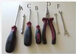
Tools
A. Tube- (or socket spanner 7)
B. Screwdriver 4mm (blade width)
C. Torx 20 screwdriver
D. Pointed pliers
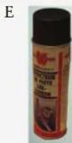
E. Leak spray and/or special pressure gauge
F. 7 + 10 open-end spanner (wok)
G. Wok insulation plate
Attention: Check the gas tightness after converting the appliance (see chapter 3).
Replace the following parts:
- injector for the burners
- simmer setting screws for the gas taps
sealing rings for the sealing under the burners - screws for fastening the burner head/drip tray on the burner
- 3 data labels with the modified gas setting
- 3 fibre rings underneath the wok burner screws
- Wok burner head (for G110 and G120 only)
- Roast burner head (for G110 and G120 only)
- Replace appliance regulator with test point adaptor (only for AU and NZ)
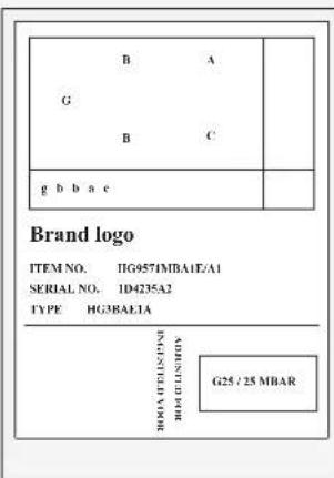
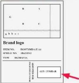
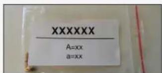
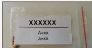
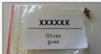
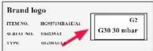
For verification, you can find the values of the injector figures and simmer setting screws on the stickers of the sets. The characters of the sets (upper case characters for injectors and lower case characters for simmer setting screws) correspond with the characters on the sticker on the base of the lower tray of the appliance. The values are also indicated on the injectors and simmer setting screws.
The following sets are possible:
- Set 'A-a' for simmer burner
- Set 'B-b' for semi rapid burner
- Set 'C-c' for rapid burner
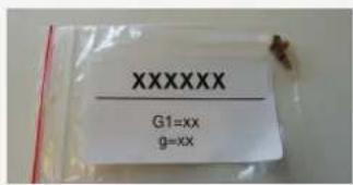
- 'G1-g', 'G2' and 'G3' sets for wok burner ('g' for simmer setting screw)
G
Examples stickers sets
Set 'A-a' for simmer burner
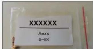
Set 'G1-g' for wok burner

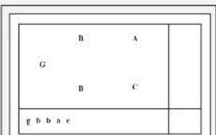
Example sticker lower tray
Dismantling (see illustration A)
Please note: disconnect the appliance before you remove the drip tray. Prevent damage of the work top. Lay down parts of the appliance on a protected base.
- Remove the pan supports and the burner heads. Pull up the control knobs vertically and remove them.
- Remove the wok burner cup and the wok heads by removing the wok distributor from the appliance (refer to the manual to do this).
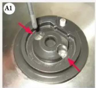
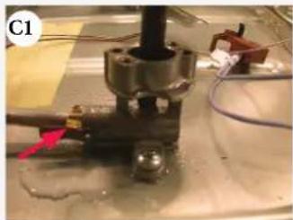
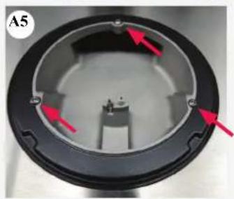
- Unscrew the burner cups (see illustration A1). For this purpose use a Torx-20 (!).
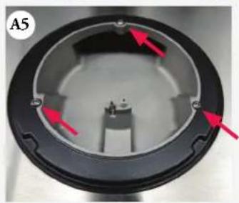
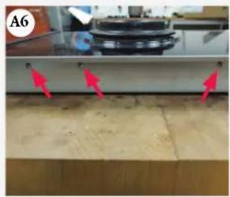
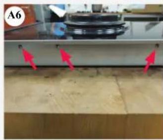
- Lift the burner cups vertically upwards. Attention: remember the position of the burner cups. The sticker in the base layer also indicates the position of the burner cups. A is the simmer burner, B the semi rapid burner, C the rapid burner and E the wok burner. For the domino wok, first remove the appliance from the recess and then remove 3 screws on the left-hand and right-hand sides (see illustration A6).
- Carefully open the drip tray at the front and slide away the pin of the grounding clip from the drip tray (see illustration A2).
- Remove the drip tray/glass plate.
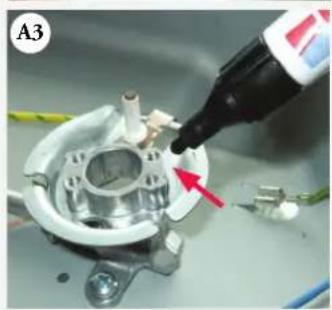
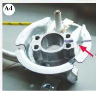
- Attention! Remember the position of the spark plug holders. Replace the spark plug holder in the same position during assembly. When necessary, mark the position of the spark plug holders (see illustrations A3 and A4).


Converting (see illustration B)
The position, the burner type (upper case character) and the tap (lower case character) are schematically indicated on the sticker in the bottom layer. There are small bags with the corresponding characters in the conversion set (see "Introduction").
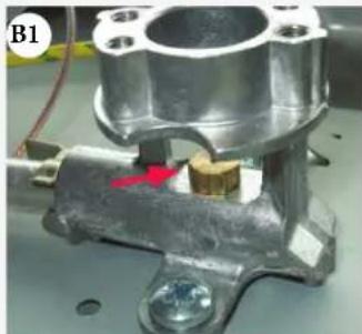
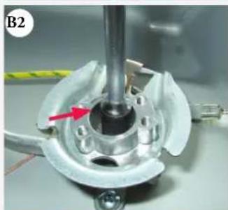
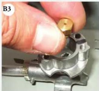
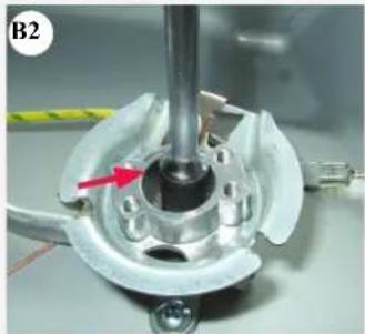
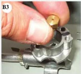
- Replace the injectors in the burners. Use a tubular spanner 7 for disassembling/assembling the injector (see illustrations B1, B2 en B3).
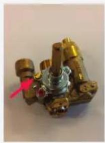
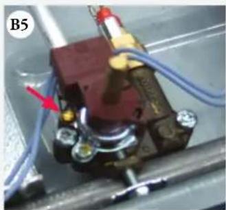
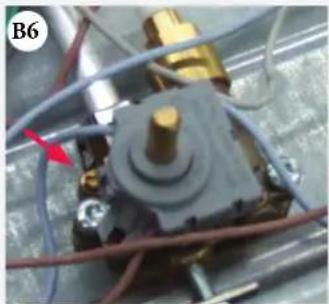
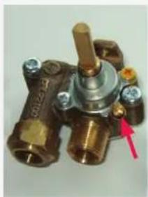
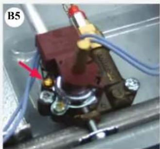
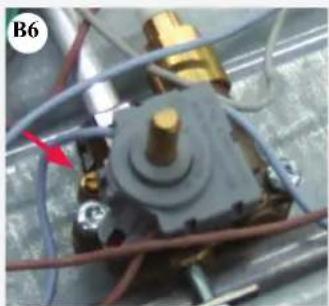
- Replace the simmer setting screws in the taps. The position of the simmer setting screw can vary per type of gas tap (see illustration B4). Use a screwdriver, blade width 4mm , for disassembling/assembling of the simmer setting screw (see illustration B5/B6) and when necessary use pliers.
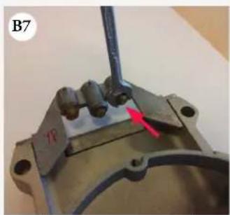
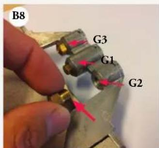
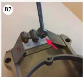
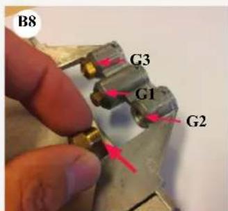
- On the wok burner, replace the injectors for simmer (G1), wok (G2) and roast (G3). The wok injector is indicated by one rib on the injector holder, the roast injector by two ribs. The simmer injector is the one in the middle (see illustrations B7 and B8). You can replace the simmer injector with a no. 7 open-end spanner and a 3.6Nm tightening moment. Use a no. 10 open-end spanner with a 5Nm tightening moment to replace the roast and wok injectors.
For verification, you can find the values of the injectors and simmer setting screws on the data label of this set! For verification also view the values table, injector and simmer setting screws.
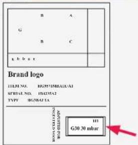
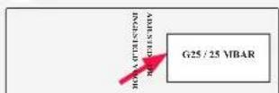
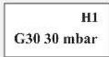
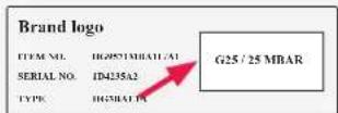
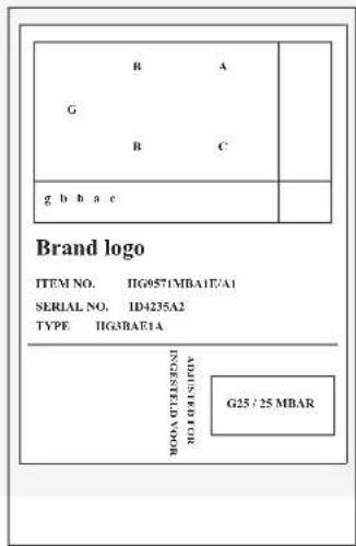
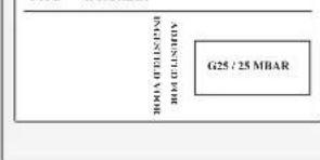
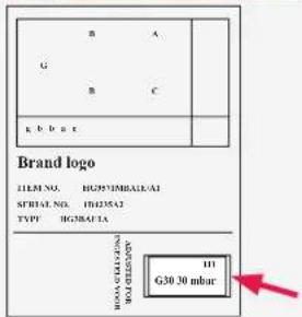
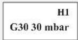
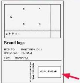
- Place the sticker 'H1' in the appropriate block on the current appliance identification card (with the type of gas/gas pressure) in the bottom tray (see illustrations B9, B10 and B11).
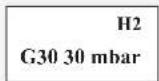
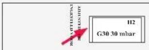
- Place the sticker 'H2' in the appropriate block on the current appliance identification card (with the type of gas/gas pressure) on the underside of the bottom tray (see illustrations B9, B12 and B13).
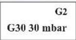
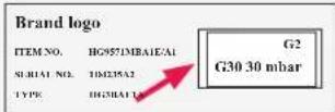
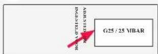
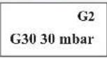
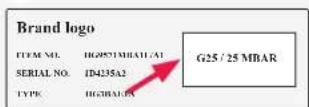
- Place the sticker 'G2' in the appropriate block on the current appliance identification card (with the type of gas/gas pressure) on the back of the user manual (see illustrations B9, B14 and B15).
Warning!
Check the appliance for gas tightness, especially the injectors and simmer setting screws!
Always check for gas tightness before using the appliance! Check the other injectors first before checking the roast injectors.
Please note: to do this, connect the appliance to the mains.
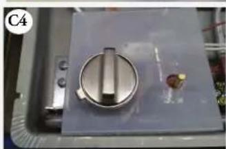
Do not forget to use the insulation plate!
B4

B11
B12
B13

B9
B14
B15
B10
This labels are examples and could different for other kind of gases.
Check for gas tightness (see illustration C)
Use leak spray to check the gas tightness when the appliance is connected to the gas supply:
- Seal the injector.
- Open the gas tap. Attention; press and open taps with thermo electric safety device and keep them pressed!
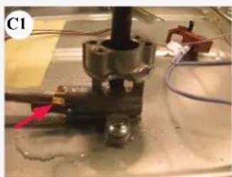
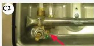
- Spray leak spray on the connections and check them for gas tightness (see illustrations C1 and C2).
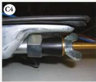
- When checking the gas density of the wok or roast injectors, the simmer injector must also be closed off. When checking the roast injector (wok), connect the appliance to the mains to be able to turn on the solenoid. Position the insulation plate to shield any live parts (switch) (C4).
When checking gas density, always leave the roast injector until last. Always use the sealing ring and the control knob. Refer to the manual. Be careful of any live parts.
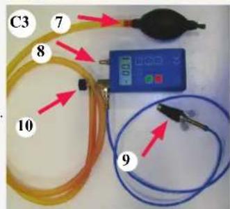
Check the gas tightness with a pressure pump (see illustration C3) when the appliance is not connected to the gas supply:
1. Connect the pressure pump to the gas pipe (see illustration C4) and close all gas taps.
2. Increase the pressure to 150 mbar and close the tap (see illustration C3/10) between the pressure pump and the pressure gauge (see illustration C3/8). Check the pressure. The maximum pressure loss may amount to 5 mbar per minute. After checking, open the tap (see illustration C3/10) between the pressure pump and the pressure gauge.
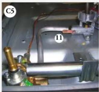
3. Open one of the taps and close the corresponding injector (see illustration C5/11).
Attention: press and open taps with thermo electric safety device and keep them pressed!
4. Increase the pressure to 150 mbar and again close the tap between the pressure pump and the pressure gauge. Check the pressure. The maximum pressure loss may amount to 5 mbar per minute.
5. Repeat this test for all taps and injectors.
You may use an other approved method for checking the gas tightness.
Final assembly (see illustrations D)
- Check the position of the spark plug holders. Incorrectly positioned spark plugs can result in incomplete combustion.
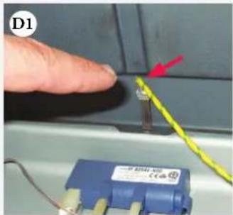
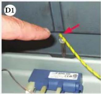
- Place the drip tray on the appliance. Do not forget to connect the earth cable to the drip tray (see illustration D1)!
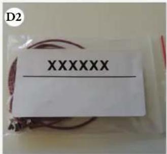
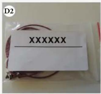
- Place new seal rings in the burner cups (see illustration D2). Screw the burner cups onto the burners with new torx-screws.
- Position new fibre rings underneath the wok burner screws.
Start up
- Put the knobs, the wok burner cup, the burner heads and the pan supports in position. For G110 and G120, replace the wok burner head and roast burner head with the burner heads included in the conversion set.
- Check whether the appliance is connected to the correct type of gas and gas pressure.
- Open the gas supply and insert the plug into the power socket.


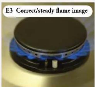
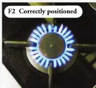
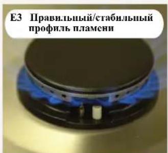
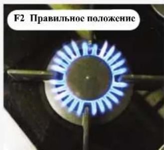
Checking operation (see images E/F)
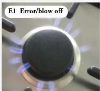
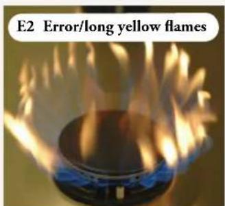
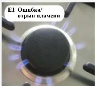
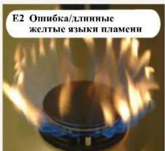
Ignite the burners. Check whether the flame profile is uniform and stable for the complete flexibility ratio (see illustrations E1, E2 en E3).
Important for this is that:
- The flame does not smother in simmer rate, the burner does not 'blow off' at maximum burning (to be recognized in flames that are at a distance from the burner in combination with a 'hissing' sound) and there are no long yellow flames.
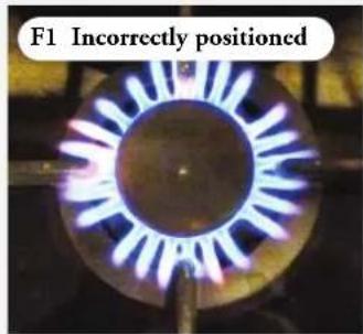
- The burners are positioned correctly (see images F1/F2).


| Gas table | G20 20 mbar | G20 13 mbar | G25 25 mbar G25.3 25 mbar | ||||
| Burner | Inscript- tion injector | Inscription sim- mer setting screw | Inscript- tion injector | Inscription simmer setting screw | Inscript- tion injector | Inscription sim- mer setting screw | |
| Aa= Simmer | 77 36 | 85 45 | 75 36 | ||||
| Bb= Semi rapid | 106 45 | 117 60 | 107 45 | ||||
| Cc= Rapid | 131 53 | 135 65 | 132 53 | ||||
| G1g= Simmer | 61 40 | 66 60 | 70 40 | ||||
| G2= Wok | 110 | 110 | 110 | ||||
| G3= Roast | 180 | 210 | 190 | ||||
| Gas table | G30/G3128-30/37 mbar | G30/G3150/67 mbar | |||
| Burner | Inscript-ion injector | Inscription sim-mer setting screw | Inscript-ion injector | Inscription simmer setting screw | |
| Aa= Si | nmer | 46 26 | 46 22 | ||
| Bb= Semi | rapid | 60 30 | 60 26 | ||
| Cc= Rapid | 72 36 | 72 30 | |||
| G1g= Simmer | 40 34 | 40 34 | |||
| G2= Wok | 61 61 | ||||
| G3= Roast | 100 100 | ||||
| Gas table | Natural gas (N.G.) 1Kpa (Au/Nz) | ULPG 2.75Kpa (Au/Nz) | |||
| Burner | Inscript- tion injector | Inscription simmer setting screw | Inscript- tion injector | Inscription simmer setting screw | |
| Aa= Small | 90 45 | 48 26 | |||
| Bb= Medium | 120 60 | 66 30 | |||
| Cc= Large | 135 65 | 77 36 | |||
| G1g= Wok Simmer | 66 65 | 40 34 | |||
| G2= Wok inner | 120 | 63 | |||
| G3= Wok outer | 210 | 100 | |||
Let op:
Sett "A-a" for småkokerbrenner
Sett "G1-g" for wokbrenner
Eksempel etikett nedre brettEksempler etike
CytncbYOT cJeIyIOHHe KOMIIeKtBt:
KOMIIeKT A-a] KHOHOpKN BapKn HA MeJeHHOM OrHe;
- KOMIIIEKT《B-b》HJKOHΦopKn cpcHcToOrH;
- KOMIIeKrT «C-c» nIa KOHΦoPkn ycnHeHHoro orTHA;
- KOMIIeKtIgG1-g,G2>H G3)nKoHΦopKn DnBOK(g)npeYINPBOOHTHO BHHaMeHHeHOrO OrHn.


PnHmepbKOMJIeKToB HAKTeE
KOMIIeKT A-a) KOHOpKP NnBAPKN HA MEJIeIHIOIOM ORIE
KOMIeKT《G1-g》HIO KOHΦOpKN HIN BOK
PnHmep HAKJIeIK HA HIXKHEM JOTKe
Brand logo
ITEMNO. HJ9957IMBAE/AI
SERIAL NO. 1D4235A2
TYPE HG3BA1A
Pa360pka (cm. pncyHok A)
Bnmaue! Npeod cunmuem kaniecboopa omknoumepnpob. He donykaume nopeocdenpaoboei noeepxhcmu. Ykaabiaume demaru npubopa na noeepxhcmb, nokpmyo 3aunmhbM mamepuanlOM.
- CHHMMTE ONOPHYO peIeKy H rIOBKn KOHΦoPOK. BbTnHITeperyHpyIOIIHe pyKu BEPTHKaJIbHO BBepx H CHHMMTE HX.
- CHHMMTe yu ky KOHΦopKn DJI BOK H KOHΦopKn DJI BOK, CHAB C IHTbI paIIpeJeHTeJIb DJI BOK (IOpAIOK CHRTN OINCAH BY PYKOBOCTBC).
- OTKpyTHTE HAMKOHΦOPOK (cm. pncyHOK A). HcnoJIb3yIe IIN 2TOrO KIOUq Torx-20 (!).
4.ПОДИМЛТЕ VAHIN KOHΦOPOK BEPTKAKJIIBHO BVEPX. BnHMaHHe! 3aONMHTe pacnoJIOKeHne YAH KOnΦopok. OHO yKa3aHO TAKKE Ha HAKTEIke HA OCHOBAHII. A O3HaJaET KOHΦOpky IIA BapKn HA McTeIHOM ORTH, B — KOHΦOpKY O6bTHORO ORTH, C— KOHΦOpKy ycJIeHHORO ORTH, a E — KOHΦOpKY DII BOK. IIpN CHaTHN OTDeIbHOI KOHΦOpKN DII BOK, cIEyET ChaHaJIa BBHyT IpH6Op H3 rHE3Ia, a 3aTeM BbIKpyTHTB 3 BnHTa CJIeBa H cIpaba (cM. pncvHOK A6).
5.OctopOKHOOTKPOHTe KANIEc6OpHN CnepEn H BbHbTe H3 Hero ⅢTHΦT3aKHMA 3a3EmJIeHHA (CM.PHCyHOK A2).
6.CINMMTE KANIEc6OpHHK/CTeKJIIMHIO NOBepxHOCb.
7.BHHMaHHe! 3aHOMHHTpe paIOJOKeHHe IepKaTeJIe CBey 3aKHaHH.
IIpu c6OpKe Hx IeO6XoHMo 6yET yCTaHOBHb Ha CBOH MecTa.
EeHN Heo6XoHMo, IOMeTbe paIOJOKeHHe IepKaTeJIe CBey 3aKHaHH (cm. pHyIKn A3 II A4).


Ipcoc60pyoobanhe (cm.phcynokB)
PacnooKemue, munbi konupopok (azaabna hykba e obosnauu) u munonomunb kpanoB (cmpouan hykba 6 oboaenuu) cxemamueecku ykaaun na nakteke na nuhcm tomke. B komtkm dne nepeobopydoaunxodm haktu c coomgemmayouumykbam, yloocenhbe nakemukc (m. «BedeHue).
- YcTAnOBHTe KHKJIepb KoHΦopOK.ДЯ CINrTHa H yctanOBKn KHKIepoB HcNoJb3yIte Tpy6aTbKIO7 (cm.pncyKN B1,B2nB3).
- YcTaHOBHTe BHTbpeyHpOBKn MeJHeHHoro OR H Ra3OBHX KpaHax. NIOToKHe BHTa peryHpOBKn MeJIeHHoro OR HA MoKet 6bITb pa3NHybIM, B 3aBHCHMOCTH OT rA3OBOr KpaHa (CM. PHCyHOK B4). BbIKpyHBAHTe H 3aKpyHBAHTe BHT peryHpOBKn MeJIeHHoro OR HA C IOMOUBIO OTBePTKN C IIHPHHoI Je3BHA 4 MM; IIIN He06XOnMOCTH HcNOJb3yIte NaCCaTHKn.
- B KOHOPKc IIN BOK yCTAHOBHTE JHKJIePbI MEJIEHHORO OTTH (G1), BOK (G2) H JkapeHHa (G3). Ha JepKaTeJIb JHKTEpa IIN BOK HAHCCIIa OJIIa p6OpTa, a IIN JkapeHHra -Ibc. JHKJIeP MeJIEHHORO OTTH paCNOIOKeH IOcepeHHe (cm. pncyHKn B7, B8). IIN YCTAHOBKH JHKJIePbI MEJIEHHORO OTTH CJEyET IINJB3OBaTbCBraeHHbIM KJIOHOM COTKpbITbIM 3CBOM No 7; MOMHT 3aTARHBaHIIH 3,6HM. IIN YCTAHOBKH JHKJIePbOB JINJkapeHHa IIN BOK CJIeDyET IINIB3OBaTbCBraeYHbIM KJIOHOM COTKpbITbIM 3CBOM No 10; MOMHT 3aTARHBaHII5HM.
KoHmpoIbIbe npamempb Icukiepo6 u nacmpoukpezyuupooohbx buhmos Mediennozo 021 naenebn ha hakteku, 6xodraue 6 konmTekm. KoHmpoIbIbe npamempb Icukiepo6 u pezyuupooohbx buhmos Mediennozo 021 yka3aibn maKnce 6 maOuue npamemp6.
- HaHcHTe HAcIcy (H1) B COOTBCTCTBYIOICM 6JOKC ICHTHINKAnHOHHoH KApTb np6opa (c ykaaHem BHa HaaJIeHHra3a) Ha HxKHe JOTKe (cm. pHyKn B9, B10 n B11).
- HaHeCNTe HAKJEKy H2 B COOTBECTBYIOEM 6IOKE IIEHTHΦKAIOHOHKO KAPbI INp6opa (c yka3aHHem BnHa HabJIeHHra3a) HA HIXKHeI NOBepxHOCTH HIXKHeO IOTKa (cm. pHyHK B9, B12 n B13).
- HahecheHte HakJeKy «G2» B COOTBETeRbYIOHem 6IKe HJENTHdHKAHHOHIO KAPbI pH6opa (c ykaaHem BNHa HnabHeHHra3a) Ha opaTHoC tOPOHe 6IooKHN pyKOBOCTBa IIOB3OBATcI (cm. pHyCN B9, B15 n B16).
Bhumahne!
IpoBepbTe Ra30nIOrHocTb np60pa, oO6eHHo JHKJIePoB H peryIHpOBouHbIX BHTOB MeIeHHOrO orH!
IpeKHe Yem npHcyTnATb K 0KcNpyaunn npH6opa, 063aTe.1bNo npOBepnre raonIOTHocB!
IpeKJIe YEM npOBepaTb KHKJepbl IIN KapeHH, ChauJa npOBepbTe ocTaJIbHbE KHKJepbl.
06paHTe BHHMaHHe: 1B3T010 Heo6xOHNMO HIOKHOHTb np6op KJIeKtPoCetn.
He 3a6yIbTe yctanOBHTB H30.TaHNOHHyIO mactHy!


B4
B11
B12
B13
B9

B14
B15
B10
IpoBepbTe Ra30nIOthocTB (cm. pHyHK C)
IIOKIIIOHbIpH6Op K HcTOUHHky Ra3a, IPOBcPbTe Ra3OIIIOHTHOCTb C NOMOIIbIO cIpCe TIN NOHCkA YTCueK. 1Ia 3TOro BbIOJIInHe CJeIyIOHne DeiCtBn.
1.3aIyInrTe OTBepTne KHKJepa.
2. OTKpoIte Ra3OBbI KpaH. BHMaHHe! Ra3OBbc KpaHbI C TcPmO3JIckTPHcCKHM IpeIOxpaHHTe.IbHbIM YcTPOHCTBOM CJCJYCT OTKpbHbATb, HAKHM H VcPcKBaB B HaKaTOM IOIOCHHH.
3. Haehcntc cnpreHa Mecta cocdHHeHHn H npOBepbrcnx Ha ra3oNIOrHocTb (cm. pHyKn C1 n C2).
4. Ipn npOBepKe RaOIOIOTHOCTH KHKIEPOB DIA BOK HIN DIA JAPeHHJXKIEP DIA BApKN HA MeIeHHOM ORHe TaKe CneDyET 3aIyUHTb. Ipn npOBepKe RaOIOIOTHOCTH KHKIEPA DIA BOK IOKIOHOTHE IpNoOp K OJIeKTPOcTe, YTO6BI MOR cpaOaTb OJIeKTPoAMrITMbIKnAaII. YCTAOHObTE HIOJIIOHIOHIOIIOIACTHNY, YTO6BI ORaHTb DEaTIH, HaxoJIMHeCecNIOI HAnpRKeHEM (BkIKHOaTeJIb) (C4). FAOIOIOHOTcB XKIEpeA DIA JAPeHHJBCTeIeYIpOBepBT BIOCEIIOIO OepeJIb. BcerJa IOIB3yIteCb yIIOHTCBILM KOJIbOM HpyKOH peYrTota. CM. pyKOBOCTBO. ByIbTC ocToPOKHIb IIpn paOBe TpAOm C KaKHMI-JH60 DeaJIaMH, HAXOJIMHMncIIOI HAnpRKeHEm.
PpOBepBte raonIOTHocTB HArHeTaTeNBbIM HAcOCOM (cm. pHyOK C3), KOrda PpHOp Ne NOKIOUcH K HCTOuHKy rA3a:
- PIOKIOHHTe HArHrTeJIbIbI HAcOc K Ra3OBoT py6e (cm. pncyIOK C4) 3aKpOITe Bce ra3OBbIe KpaIIbI.
- YBeJIHbTe IaJIeHHe IIO 150 M6ap H3aKpOHTe KpaH (cm. pHyHK C3/10) MeKJy HArHeTaTeIbHbIM HaCOCM MaHOtPOM (cm. pHyHK C3/8). HaIOJIaIIte 3a H3MeHEHHEM DAJIeHn. MaKcHMaJIbHOe IaJIeHne IaJIeHn MOKeT CoCTaBHTIb 5 M6ap/MIII. PocIc IIPOBcPKH OTKpoHTc KpaH (cm. pHyHK C3/10) MeKJy HArHeTaTeIbHbIM HACOCM mHaHometPOM.
- OTKpoIte OINH H3 KpaHOB H 3aRyUInTe COOTBCTBYUHNI JHKnep (cM. pHyOH C5/11). BHHMaIIe! RaOblBe KpAHIc TpeMOIOETrpueCKNpIeNOxPAHITeJIbHM yctpoiCTBOM cJeYer OTKpIBATb, HAKMaH N UePckHbA B HAKAtOM IOJOKChHn.
- YBeJIHbIe IaBHeHne 150 mbap n cHOBA 3akpoIte KpaH MeKdy HAIHTeJIbHbIM HaCOOM H MaHOMeIpOM. HaIOJATc 3a H3MCHINHE TaBICIHH.MaKCHMaTbHOC IaChHc IaBHeHH MoKcOCTABJIITb 5 M6ap/MHH.
5.IOBTOHPTE 3TO HcNbITAHNE IJI BCEx KpaHOM JIKKIEPOB.
OkoHuaTe.1bHaA c6opka (cm. pncyKn D)
- IIpoBepBe pacIOIOKeHHe nepKaTeNe CBeY 3aKHaHH. Hx HeINpaBnIbHOe IOIOKeHHe MOKe T npHBecTH K HENIOHOMy cTropAHIO r3a.
2.YctaHOBHTcHaIpH6OpKaJIeC6OpHHK.He3a6yJBTe NOIKJIOHTb K KaJIeC6OpHHKy IpOBoIHKK 3a3cm.1CHHn (cm.PHCyHOKDl)! - YcTaNOBHTe B qaHIN KOHΦopOK HOBbE yIIOITHTeJIbIe KOTbIIa (CM. pHyNOK D2). IIpHKpyTHTE qaHIN KOHΦOpKAM HOBbIM HHTAM Htua torX.
- YcTaHOBHTe HOBbIe HOpOBbIe IaIIbI IOI BnHTbI KOHOpOK JIA BOK.
BBoI B 3KcNJyataaHIO
1.YcTaHOBHTe Ha MeTO pyK,HaIy KOHOpKN DnBOK,TOIOBKn KOHOpOK HIOCTABKn DnIOcyDbl. Ha np6opax G110 nG120 ycTaHOBHTc rOIOBKn KOHOpOK DnBOK nJIA KApChN, BXoJIINCe B KOMIIeKT dI Inepeo6OpoyOBaHH.

- Y6eHTecb, TTO npHbOp NOKIOOH K HcToHHKy r3a COOTBcTcByIOIero TnHa N daBTeHH.
- OrkpoiTe IOnaUy Ra3a H BCTaBbTe BILIKY B PO3eTKY 3JIeKTPocetH.
KoHTpoIb pa6Otb (cm. pnc. E/F)
3aKHTRE ropeKN. Y6eHITecb, HTO npoHb IIaMeHN OAnOpOeH N yCTOHNB BO BcEM dHaIIa3OHe peryHPOBAAH (cm. pncyHK E1, E2 n E3).
PnTOMBaKHO:
-TO6bIeBpKHeBAPKnHMeJIeHHOMOTHEIIAMHeKOITIO,IPNMAKCHMAJBHOMOTHEIEPOHCXOJIICpBIBIIaMEIN(KOrlaIIaMnIOBRICTcHpaCtOHHNOT KOIΦOPKN,ANOTOKra3aBBIXOHTCOCBHCTOM)HTO6bIEbIIOIIHHBxJKeTbIXABIKOBIIaMeHN。
-TopeJKN paIIOJOKeHb IpaBnHbHO (cm.pHC.F1/F2).

- Attention:
- Introduction
- Tools
- Attention: Check the gas tightness after converting the appliance (see chapter 3).
- Replace the following parts:
- Examples stickers sets
- Example sticker lower tray
- Dismantling (see illustration A)
- Converting (see illustration B)
- Warning!
- Check for gas tightness (see illustration C)
- You may use an other approved method for checking the gas tightness.
- Final assembly (see illustrations D)
- Start up
- Checking operation (see images E/F)
- Let op:
- CytncbYOT cJeIyIOHHe KOMIIeKtBt:
- PnHmepbKOMJIeKToB HAKTeE
- PnHmep HAKJIeIK HA HIXKHEM JOTKe
- Brand logo
- Pa360pka (cm. pncyHok A)
- Ipcoc60pyoobanhe (cm.phcynokB)
- Bhumahne!
- IpoBepbTe Ra30nIOthocTB (cm. pHyHK C)
- OkoHuaTe.1bHaA c6opka (cm. pncyKn D)
- BBoI B 3KcNJyataaHIO
- KoHTpoIb pa6Otb (cm. pnc. E/F)
Brand : ASKO
Model : HG1825AB
Category : Cooker