
DigitRadio UP 1 - Radio TECHNISAT - Free user manual and instructions
Find the device manual for free DigitRadio UP 1 TECHNISAT in PDF.
| Product type | Flush-mount FM/DAB+ radio with Bluetooth |
| Brand | TechniSat |
| Model | DigitRadio UP 1 |
| Reception frequencies | DAB/DAB+: 174.928 - 239.200 MHz; FM: 87.5 - 108 MHz |
| Audio power | 2 W RMS |
| Power supply | 100 - 240 V AC, 50 ~ 60 Hz |
| Operating power consumption | 5 W max |
| Standby power consumption | < 1 W |
| Dimensions (radio unit) | 152 mm x 81 mm x 48 mm |
| Main functions | DAB+/FM reception, Bluetooth streaming, alarm, sleep timer, equalizer (treble/bass), time and date display, RDS |
| Presets | 10 DAB+ stations and 10 FM stations |
| Alarm | 2 independent alarms with choice of source (buzzer or radio) and repetition (once, workdays, weekend, daily) |
| Equalizer | Treble and bass adjustment from -5 to +5 |
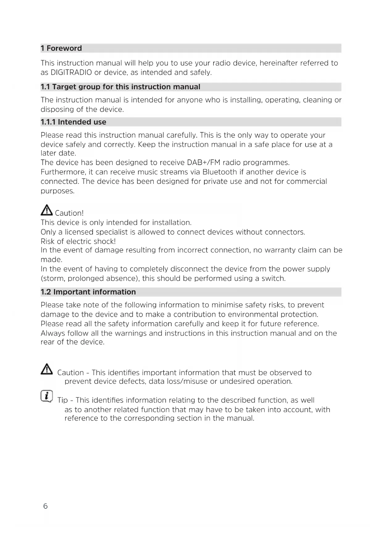
| Display | Screen with time, date, station information (scrolling text, signal strength, etc.) |
| RDS | Display of station name, radio text, program type |
| Bluetooth connectivity | Version not specified, range ~10 m |
| Maintenance | Clean with a soft, dry cloth. Do not use abrasive products or solvents. |
| Safety | Installation by a qualified professional. Do not open the device. Do not expose to moisture. |
| Supplied accessories | Antenna, double mounting frame, fixing kit, instruction manual |
| Warranty | 24 months statutory from date of purchase |
Frequently Asked Questions - DigitRadio UP 1 TECHNISAT
User questions about DigitRadio UP 1 TECHNISAT
0 question about this device. Answer the ones you know or ask your own.
Ask a new question about this device
Download the instructions for your Radio in PDF format for free! Find your manual DigitRadio UP 1 - TECHNISAT and take your electronic device back in hand. On this page are published all the documents necessary for the use of your device. DigitRadio UP 1 by TECHNISAT.
USER MANUAL DigitRadio UP 1 TECHNISAT
DAB+/FM recessed radio with Bluetooth
Contents
1 Foreword 6
1.1 Target group for this instruction manual....6
1.1.1 Intended use 6
1.2 Important information....6
1.2.1 Safety....7
1.2.2 Disposal 8
1.2.3 Legal notices....10
1.2.4 Service instructions....10
2 Illustration and buttons....11
3 Connection and assembly of the DIGITRADIO UP1 12
4 Description of the DIGITRADIO UP1....13
4.1 Scope of delivery....13
4.2 The special features of the DIGITRADIO UP1....13
5 General device functions....13
5.1 Switching on the device 13
5.2 Switching off the device 13
5.3 Changing to DAB+/FM/Bluetooth mode 13
5.4 Adjusting the volume....13
5.5 Retrieving displays....14
6 Menu operation....14
7 DAB+ (digital radio) function.... 15
7.1 What is DAB+? 15
7.1.1 Data compression....15
7.1.2 Audio stream....15
7.2 DAB+ (digital radio) reception....15
7.2.1 Performing a complete scan 15
7.2.2 Selecting stations....16
7.2.3 Storing DAB+ stations on a memory slot....16
7.2.4 Retrieving DAB+ stations from a memory slot 16
7.2.5 Overwriting/deleting a station memory slot 16
7.2.6 Signal intensity....17
7.2.7 Manual setting 17
7.2.8 Volume adjustment (DRC)....17
7.2.9 Deleting inactive stations....17
8 FM mode....18
8.1 Switching on FM radio mode 18
8.2 FM reception with RDS information....18
8.3 Automatic station scan 18
8.4 Manual station scan....18
8.5 Scan setting 18
8.6 Audio settings....19
8.7 Saving FM stations to a memory slot....19
8.8 Retrieving FM stations from a memory slot....19
8.9 Overwriting/deleting a station memory slot....19
9 Bluetooth....19
9.1 Pairing a device 20
9.2 Bluetooth playback....20
10 Other functions.... 21
10.1 Sleep timer....21
10.2 Alarm 21
10.2.1 Setting the alarm time.... 21
10.2.2 Switching off the alarm after being woken....22
10.2.3 Deactivating the alarm....22
10.3 Equaliser....22
11 System settings....23
11.1 Time and date settings....23
11.1.1 Manually setting the time/date 23
11.1.2 Time update....23
11.1.3 Setting the time format....24
11.1.4 Setting the date format 24
11.2 Display brightness 24
11.3 Language....25
11.4 Factory setting....25
11.5 Software version....25
12 Cleaning 26
13 Troubleshooting 26
14 Technical data....27
15 Installation 27
1 Foreword
This instruction manual will help you to use your radio device, hereinafter referred to as DIGITRADIO or device, as intended and safely.
1.1 Target group for this instruction manual
The instruction manual is intended for anyone who is installing, operating, cleaning or disposing of the device.
1.1.1 Intended use
Please read this instruction manual carefully. This is the only way to operate your device safely and correctly. Keep the instruction manual in a safe place for use at a later date.
The device has been designed to receive DAB+/FM radio programmes.
Furthermore, it can receive music streams via Bluetooth if another device is connected. The device has been designed for private use and not for commercial purposes.
Caution!
This device is only intended for installation.
Only a licensed specialist is allowed to connect devices without connectors.
Risk of electric shock!
In the event of damage resulting from incorrect connection, no warranty claim can be made.
In the event of having to completely disconnect the device from the power supply (storm, prolonged absence), this should be performed using a switch.
1.2 Important information
Please take note of the following information to minimise safety risks, to prevent damage to the device and to make a contribution to environmental protection.
Please read all the safety information carefully and keep it for future reference.
Always follow all the warnings and instructions in this instruction manual and on the rear of the device.
Caution - This identifies important information that must be observed to prevent device defects, data loss/misuse or undesired operation.
Tip - This identifies information relating to the described function, as well as to another related function that may have to be taken into account, with reference to the corresponding section in the manual.
1.2.1 Safety
For your own safety, you should read through the safety precautions carefully before you put your DIGITRADIO UP1 into operation. The manufacturer accepts no liability for damage caused by inappropriate handling, or by non-compliance with the safety precautions.

This device is only intended for installation. Only a licensed specialist is allowed to connect devices without connectors. Risk of electric shock! In the event of damage resulting from incorrect connection, no warranty claim can be made.

Do not open the device under any circumstances! Touching live parts poses a danger to life!

Any necessary repairs to the receiver should only be carried out by qualified personnel.

The device must only be operated in an appropriate climate.


Do not expose the device to dripping or splashing water. If water has penetrated the device, switch it off and inform the Service department.

Do not expose the device to heat sources that will heat it up more than normal use.


If you detect a device defect, odour or smoke, considerable malfunctions, or damage to the housing, switch off the device and inform the Service department.

The device must only be connected to a mains voltage of 100V-240V\~, 50/60 Hz.

Never try to operate the device with another voltage.

If the device shows signs of damage, it may not be put into operation.
Do not put the device into operation in the vicinity of baths, swimming pools or splashing water.
⚠️ Never try to repair a faulty device yourself. Always contact one of our customer service locations.
Foreign bodies, e.g. nails, coins, etc. must not be allowed to fall inside the device. Do not touch the connection contacts with metal objects or fingers. This could lead to short-circuits.
⚠️ Never allow children to use the device unsupervised.
Even when switched off and on standby, the device is still connected to the mains power supply.
Do not listen to music or the radio at high volume. Doing so can cause permanent hearing impairment.
This device is not intended to be used by people (including children) with limited physical, sensory or mental capacities or lack of experience and/or knowledge, unless they are supervised by a person responsible for their safety or they are instructed by them as to how to use the device.
Children must be supervised to ensure that they do not play with the device.
⚠️ It is forbidden to carry out modifications to the device.
⚠️ Damaged devices or damaged accessories must not continue to be used.
1.2.2 Disposal
The device packaging is exclusively comprised of recyclable materials. Please sort these and take them to the "Dual System." At the end of its service life, this device must not be disposed of with your regular household waste. It must be taken to a recycling collection point for electrical and electronic equipment.
This is indicated by the symbol on the product, the instruction manual or the packaging.
The materials are recyclable according to their identification.
An important contribution is made to our environment by recycling, recovery of materials or other kinds of recycling for old devices.

Please ask local authorities for the location of the relevant disposal point. Ensure that used batteries/rechargeable batteries as well as electronic waste are not disposed of with domestic waste, but are properly disposed of (returned to the specialist shop, hazardous waste).

natural_image
Symbol of a trash bin with crossed lines indicating no waste or restriction, and a solid black rectangle below (no text or labels)
Disposal instructions:
Disposal of packaging:
Your new device was protected by packaging on its way to you. All materials used are environmentally friendly and recyclable. Please collaborate and dispose of the packaging in an environmentally-friendly way. Ask for information from your dealer regarding current disposal means or regarding your local disposal facility.

Risk of suffocation! Do not give packaging and parts thereof to children. Risk of suffocation by films and other packaging materials.
Device disposal:
Old devices constitute valuable waste. Valuable raw materials can be recovered through environmentally-friendly disposal. Consult your town or local authority as to the possibilities for environmentally-friendly and proper disposal of the device. Prior to disposal of the device, remove the batteries/rechargeable batteries contained therein.

This device is identified in accordance with the Waste Electrical and Electronic
Equipment (WEEE) Directive 2012/19/EU.


At the end of its service life, this device must not be disposed of with your regular household waste. It must be taken to a recycling collection point for electrical and electronic equipment. The symbol on the product, the operating manual or the packaging indicates this. The materials are recyclable according to their identification. An important contribution is made to our environment by recycling, recovery of materials or other kinds of recycling for old devices.
1.2.3 Legal notices

TechniSat herewith declares that the radio system model DIGITRADIO UP1 corresponds to Directive 2014/53/EU. The complete text of the EU declaration of conformity is available at the following website:
TechniSat accepts no liability for product damage as a result of external influences, wear or improper handling, unauthorised repairs, modifications or accidents.

Changes and printing errors reserved. Version 02/18. Copy and reproduction are subject to the publisher's consent. The respective current version of the manual can be obtained in PDF format in the download area of the TechniSat homepage at www.technisat.de.

DIGITRADIO UP1 and TechniSat are registered trademarks of:
D-54550 Daun/Eifel, Germany
www.technisat.de

1.2.4 Service instructions

This product is quality-tested and provided with the legal warranty period of 24 months as from the date of purchase. Please keep your receipt as proof of purchase. In the event of warranty claims please contact the product dealer.

Note!
Should you experience a problem with this device, or for queries and information, our Technical Hotline is available:
Mon. - Fri. 8:00 am - 8:00 pm on tel.:
+49 (0) 3925 9220 1800.
If the device needs to be sent back, please use the following address only:
39418 Staßfurt, Germany
The names of the companies, institutions or makes referred to are trademarks or registered trademarks of the respective owners.
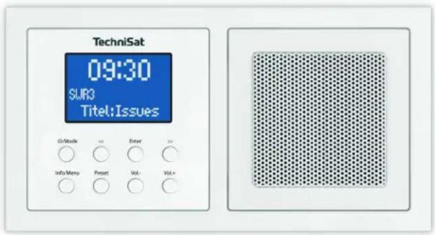
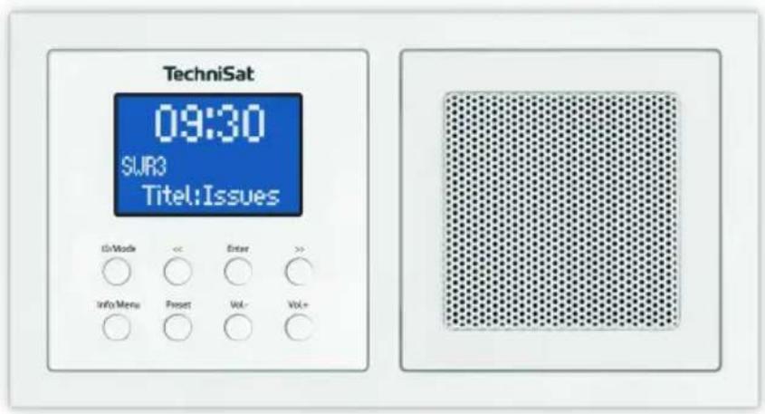
2 Illustration and buttons
1 Display
2 On/Standby/Mode change
3 Info/Menu retrieval button
4 Reduce selection/menu operation
5 Preset button
6 Enter/Confirm selection/Save/Snooze button
7 Reduce volume
8 Increase selection/Menu operation
9 Increase volume
10
Speaker
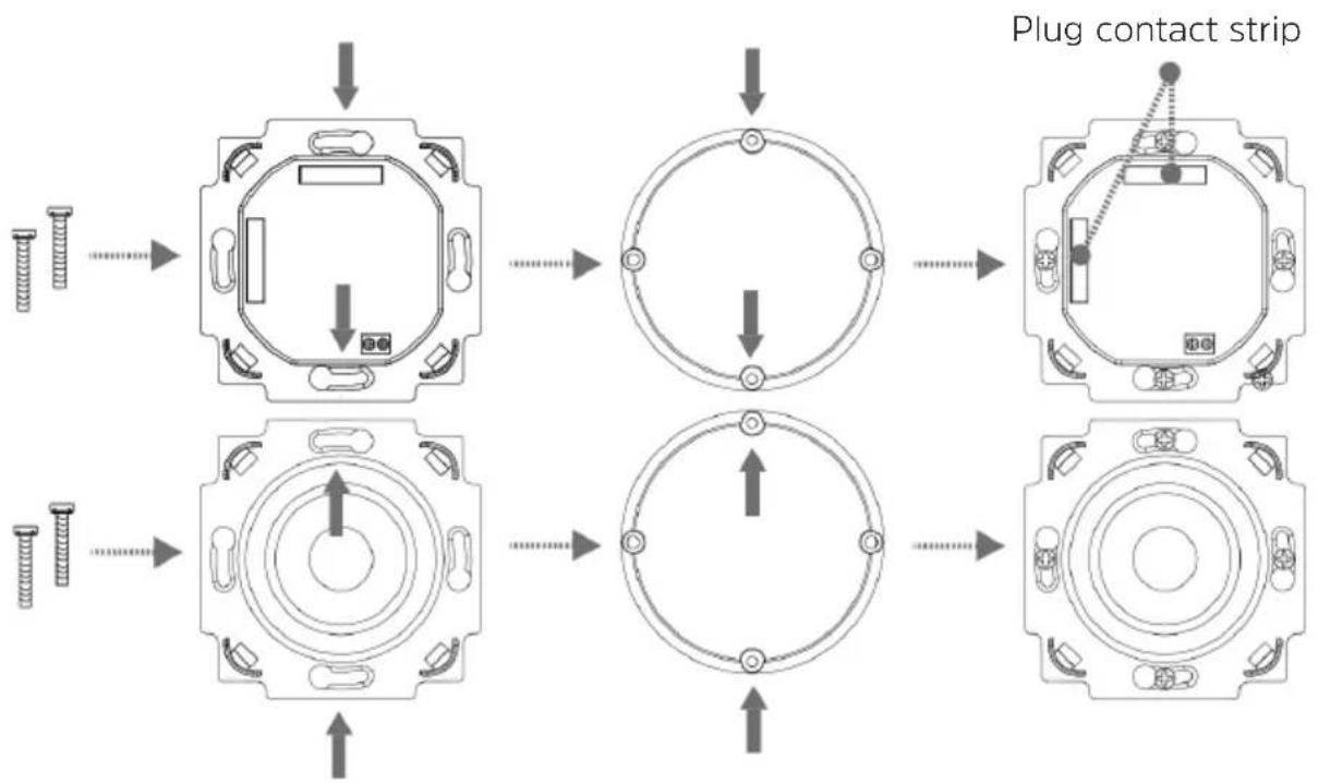
3 Connection and assembly of the DIGITRADIO UP1

Caution!
This device is only intended for installation. Work on the 230 V network may only be performed by qualified electricians. Life-threatening hazard and fire hazard from electric voltage of 230 V. Disconnect the mains power supply prior to assembly / disassembly. No claim can be made under the warranty or for liability in the event of damage due to incorrect connection.
2 x DIN flush-mounted/surface boxes are required for the radio and speaker.
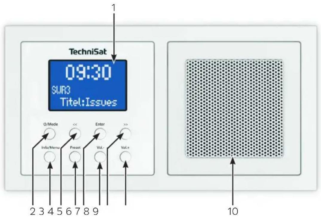
It is possible to assemble the radio and speaker in a horizontal or vertical position. When assembling the radio, ensure the correct position of the plug contacts A for the radio display operating unit.
The power supply is established via the terminal connections labelled L and N on the back of the radio unit.
The antenna must be connected to the terminal connection labelled ANTENNA.
Connect the speaker to the terminal connection B. Ensure correct polarity.

If the device is already mounted or assembled, remove the display operating unit from the radio unit with the help of the frame. If the device is in the delivery condition, remove the attachment from the radio unit using your hands. Remove the attachment using your hands only. Under no circumstances use a screwdriver or similar hard object for removal purposes. When removing, you must first of all overcome the resistance of the spring snap-in clips.
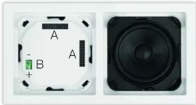
natural_image
Two electronic device components: a circular switch with labeled terminals A and B, and a black speaker grille (no text or symbols beyond labels)After successful assembly, first of all connect the display operating unit taking into account the position of the contact strip (A). To do so, carefully push the display operating unit straight onto the radio unit until it engages.

More detailed installation instructions and illustrations can be found in section "15 Installation" auf Seite 27.
4 Description of the DIGITRADIO UP1
4.1 Scope of delivery
Before start-up, please check whether everything has been delivered.
1 x DIGITRADIO UP1
1 x instruction manual
1 x Dual Installation Frame
1 x Antenna
Attachment materials
4.2 The special features of the DIGITRADIO UP1
The DIGITRADIO UP1 is comprised of a DAB+/FM receiver with the following functions:
- You can store up to 10 DAB+ and 10 FM stations.
- The radio receives on the FM 87.5–108 MHz (analogue) frequencies and DAB+ 174.9–239.2 MHz (digital).
- The device has a time and date display.
- Alarm function and sleep timer
- Music playback via Bluetooth
5 General device functions
5.1 Switching on the device
Press the /Mode button to switch on the DIGITRADIO UP1.
i After switching on for the first time the device automatically performs a complete scan in DAB mode. While scanning, the display information shows the progress, as well as the number of digital radio stations detected. After completing the station scan the first DAB+ channel is played.
5.2 Switching off the device
Keep the /Mode button depressed to switch the device to standby mode. [Standby] appears briefly on the display. The date and time are shown on the display. The display brightness in standby mode can be adjusted by following the instructions in section 11.2.
5.3 Changing to DAB+/FM/Bluetooth mode
Press the ⏻/Mode button briefly to switch between DAB+ (Digital Radio), FM and Bluetooth.
5.4 Adjusting the volume
Adjust the volume using the Vol +/- buttons. The set volume is shown on the display by way of a bar chart.
5.5 Retrieving displays
Press the Info/Menu button repeatedly to scroll through the information available. You have the choice of viewing the following information:
In DAB+ mode (the selected function is identified with an “*”):
[Running text] (continuous text with additional information provided by broadcasters etc.), [Signal intensity], [Channel type], [Ensemble], [Frequency], [Signal quality], [Bit rate and Codec], [Time] and [Date].
In FM mode (the selected function is identified with an “*”):
[Radio text] (if transmitted), [Channel type] (PTY), [Ps] (Programme Service Name or Station Name or Frequency), [Audio Information], [Time] and [Date].
6 Menu operation
All the DIGITRADIO UP1 functions and settings are accessed via the menu. The menu navigation takes place using the Info/Menu, <<, >> and Enter buttons.
The menu is divided into submenus and, depending on the mode (DAB+ or FM), contains different menu items or functions which can be enabled. To open the menu, keep the Info/Menu button depressed. To change to submenus, first of all press the << or >> buttons to display a submenu, then press the Enter button to retrieve the submenu. An asterisk (*) highlights the current selection.
Close menu: press the Info/Menu button repeatedly (depending on which submenu you are in), or wait until the current radio channel is displayed again.
Settings are not saved until the Enter button is pressed. If the Info/Menu is pressed instead, the settings are not confirmed and saved (the Info/Menu button in this case acts as a "Back" button).
The functions and buttons to be pressed are shown in bold in this instruction manual. Displays in [square brackets].
i Some texts (e.g. menu items, station information) may be too long to show on the display. Shortly thereafter, these will be shown as running text.
7 DAB+ (digital radio) function
7.1 What is DAB+?
DAB+ is a new digital format through which crystal clear sound with no noise can be heard. In contrast to conventional analogue radio stations, DAB+ can be used to broadcast multiple stations on one and the same frequency. This is referred to as an ensemble or multiplex. An ensemble is comprised of the radio station, as well as several service components or data services, which are broadcast individually by the radio stations. There is information at www.digitalradio.de or www.digitalradio.ch, for example.
7.1.1 Data compression
With this, digital radio takes advantage of the properties of human hearing. The human ear does not perceive sounds which are found under a specific minimum volume. Data which are found under the so-called audibility threshold can, therefore, be filtered out. This is possible because, in a digital data stream, the relevant relative volume for other units is saved for every unit of information. Moreover, in an audio signal, the quieter parts are superimposed by louder ones at a specific limit value. All the sound information below the threshold of hearing in a piece of music can be filtered out of the signal to be broadcast. This leads to a reduction of data in the data stream to be transmitted, with no perceptible difference in sound for the listener (HE AAC v2 - supplementary codification process for DAB+).
7.1.2 Audio stream
With digital radio, audio streams are continuous data streams which contain the MPEG 1 audio layer 2 frames and thereby represent acoustic information. This enables standard radio channels to be broadcast and listened to on the receiver side. Digital radio provides you not only with excellent sound quality radio but also additional information. This may refer to the programme being broadcast or be independent information (e.g. news, weather, traffic, tips).
7.2 DAB+ (digital radio) reception
Briefly press the ⏻/Mode button until [Digital Radio] appears on the display.
If DAB+ is being started for the first time, a complete scan will be performed. After completing the scan, the first station in alphanumerical order will be played.
7.2.1 Performing a complete scan
The automatic scan [Complete Scan] scans all DAB+ band III channels and thereby finds all stations being broadcast within the reception area.
i After completing the scan, the first station in alphanumerical order will be played.
In order to perform a complete scan, open the menu by keeping the Info/Menu button depressed and use the <<, >> and Enter buttons to select the menu item [Complete Scan].
[Scan...] appears on the display.
i During the scan a progress bar and the number of stations found is displayed.
7.2.2 Selecting stations
In order to select DAB+ stations, open the station list by pressing the << or >> buttons. Confirm the station selected with Enter. The selected station is played.
7.2.3 Storing DAB+ stations on a memory slot
The programme memory can save up to 10 stations in the DAB+ range.
Now select the desired station (see section 7.2.2).
In order to store this station on a memory slot, keep the Preset button depressed while playing. Then use the <<, >> buttons to select a station memory slot (1-10). Press the Enter button to save. [Station saved] appears on the display.
Repeat this process to save other stations.
7.2.4 Retrieving DAB+ stations from a memory slot
To retrieve a station that you have stored in the FAV memory, briefly press the Preset button and select a station slot (1-10) using the <<, >> buttons. Press the Enter button to play the station.
If no station is saved on the selected station slot, [(empty)] appears on the display.
7.2.5 Overwriting/deleting a station memory slot
Simply save a new station to a favourite memory slot as described.
When retrieving the factory settings all memory slots are deleted.
7.2.6 Signal intensity
Briefly press the Info/Menu button repeatedly until the signal intensity is shown on the display by way of a bar chart.

Current signal intensity
Minimum signal intensity

Stations with a signal intensity below the required minimum signal intensity are not transmitting a strong enough signal.
7.2.7 Manual setting
This menu item is used to check the reception channels and can be used to position the antenna.
Keep the Info/Menu button depressed, use the << or >> buttons to select the [Manual Setting] item and press the Enter button.
Use the << or >> and Enter buttons to select a channel (5A to 13F). The signal intensity will now be shown on the display. If a DAB+ station is being received on a channel, the station ensemble name is displayed.

Stations with a signal intensity below the required minimum signal intensity are not transmitting a strong enough signal.
7.2.8 Volume adjustment (DRC)
With the Volume Adjustment menu item, the compression rate is set which balances the dynamic variations and thereby the accompanying volume variations.
Keep the Info/Menu button depressed and use the << or >> buttons to select the item [Volume Adjustment].
Press the Enter button.
Select the compression rate using the << or >> buttons:
DRC high - High compression
DRC low - Low compression
DRC off - Compression switched off.
Press the Enter button to confirm.
7.2.9 Deleting inactive stations
This menu item is for removing old stations and those no longer being received from the station list.
Keep the Info/Menu button pressed and use the << or >> buttons to select the item [Delete Inactive Stations].
Press the Enter button.
This is followed by the prompt [Delete OK?], to check whether the inactive stations are to be deleted.
Using << or >>, select the [Yes] item and confirm by pressing the Enter button.
8 FM mode
8.1 Switching on FM radio mode
Briefly press the /Mode button until [FM] appears on the display.
When switching on for the first time, the frequency 87.50 MHz is set.
If you have already set or saved a station, the radio plays the last station set.
i In the case of RDS stations, the station name appears.
8.2 FM reception with RDS information
RDS is a procedure for broadcasting additional information via FM stations.
Broadcasters with RDS broadcast their station name or the programme type, for example. This is shown on the display. The device can show the RDS information RT (Radio text), PS (Station name), PTY (Programme type).
8.3 Automatic station scan
Keep the << or >> buttons depressed for longer (2 to 3 sec.), in order to automatically search for the next station with sufficient signal.
Alternatively, you can press the Enter button.
If a FM station with sufficient signal intensity is found, the scan stops and the station is played. If an RDS station is being received, the station name appears and, possibly, radio text.
i Please use the manual station scan for setting weaker stations.
8.4 Manual station scan
Briefly press the << or >> buttons repeatedly to set the desired stations or frequency.
i The display shows the frequency in steps of 0.05 MHz.
8.5 Scan setting
In this menu item it is possible to set the sensitivity of the scan.
Keep the Info/Menu depressed, use the << or >> buttons to select the [Scan Setting] item and press the Enter button.
Select whether the scan should only stop for stations with a strong signal [Strong Stations Only] or for all stations (including stations with a weak signal) [All Stations].
With the All Stations setting the scan stops automatically upon detecting each available station. This can result in weak stations being played with background noise.
8.6 Audio settings
Keep the Info/Menu button depressed and use the << or >> buttons to select the [Audio Setting] item.
Press the Enter button.
Using the << or >> buttons, select the item [Stereo possible] or [Mono only].
Press the Enter button to confirm.

Given that the DIGITRADIO UP1 is a mono device, this setting only affects the station reception intensity.
8.7 Saving FM stations to a memory slot

The station memory can save up to 10 stations in the FM range.
First set the desired station frequency.
In order to store this station on a memory slot, keep the Preset button depressed while playing. Then use the <<, >> buttons to select a station memory slot (1-10). Press the Enter button to save.
Repeat this process to save other stations.
8.8 Retrieving FM stations from a memory slot
In order to retrieve a station that you have previously stored in the FAV memory, briefly press the Preset button and use the <<, >> buttons to select a station memory slot (1-10). Press the Enter button to play the station.

If you have no station saved to the selected station slot [(empty)] appears on the display.
8.9 Overwriting/deleting a station memory slot
Simply save a new station to the respective memory slot as described.

When retrieving the factory settings all memory slots are deleted.
9 Bluetooth
Briefly press the ⏻/Mode button until [Bluetooth] is shown on the display.
If Bluetooth mode is being launched for the first time, a playback device, e.g. a smartphone or tablet, must be paired with the DIGITRADIO UP1.
If a playback device has already been paired once and it is located in the reception range, it will be automatically connected.


9.1 Pairing a device
Select Bluetooth mode on the DIGITRADIO UP1. The display shows [Bluetooth Visible].
Open the Bluetooth settings on the smartphone/tablet that you wish to pair with the DIGITRADIO UP1.
Launch the search for available Bluetooth devices.
From the list of detected Bluetooth devices, select the DIGITRADIO UP 1 item.
Once successfully paired, [Bluetooth Connected] appears on the display.

Please refer to the instruction manual for your smartphone/tablet as to how to use the Bluetooth function on your smartphone/tablet.
9.2 Bluetooth playback
Once you have successfully paired your smartphone/tablet with the DIGITRADIO UP1, you can start playing audio. Open a music app on your smartphone/tablet and start playing music. Depending on the smartphone/tablet, the sound will either be played directly via the DIGITRADIO UP1, or you will first of all have to select the DIGITRADIO UP1 as the playback device. Please refer to the instruction manual for your smartphone/tablet as to how to select playback devices via Bluetooth on your smartphone/tablet.
To pause playback, press the Enter button, or pause via the music app on your smartphone/tablet. Press the button again to continue playback.
To skip to the next track, press the >> button, or select the next track in the music app on your smartphone/tablet.
If you would like to listen to the track currently being played from the start, press the << button once. To skip to the previous track, press the << button twice. Alternatively, use the music app on your smartphone/tablet.
The volume can be adjusted using the Vol+/- buttons, or with the volume control on your smartphone/tablet.

Control of the smartphone/tablet via the DIGITRADIO UP1 is only possible with supported devices.

Depending on the smartphone/tablet, ring tones or system tones can also be transferred.
10 Other functions
10.1 Sleep timer
You can activate the sleep timer if you want the DIGITRADIO UP1 to switch to standby automatically after a specific time.
Keep the Info/Menu button depressed and use the << or >> buttons to select the [Sleep] item.
Using the << or >> buttons, you can set the period as intervals of Off, 15, 30, 45, 60 and 90 minutes, after which the device is switched to standby from any operating mode.After selecting a time interval press the Enter button.
In the top left corner of the display, a clock symbol appears to indicate that the sleep timer is active.
If you retrieve the Sleep timer menu again, the remaining running time is shown.
10.2 Alarm
Keep the Info/Menu button depressed and use the << or >> buttons to select the [Alarm] item.
10.2.1 Setting the alarm time
The wake-up function cannot be operated until the correct time has been set. Depending on the configuration, this occurs automatically or must be set manually. The time can either be updated manually or via DAB/FM. See Section 11.1 for further information.
Select an alarm time memory (alarm 1 or alarm 2) using the << or >> buttons and confirm with Enter.
Go through all the points one after the other. Confirm each entry with the Enter button:
[Alarm Time] > Set the time you wish to be woken at using the << or >> buttons and press Enter.
[Duration] > set the duration of the alarm using the << or >> buttons and press Enter.
[Source] > Select the wake-up tone (buzzer or radio source) using the << or >> buttons and press Enter.
If you have selected digital radio (DAB) or FM as the wake-up tone source, you can then select a station from the station list or the last selected channel as the playback source. Then press Enter.
[Repeat] > In this case select the days on which the alarm should be active.
You can choose between daily, once, weekends (Sat. and Sun.) and working days (Mon. - Fri.). Then press Enter.

If you have selected Once, you must then enter the date on which the alarm should be active.
[Volume] > With the << or >> buttons, select the volume at which you wish to be woken. Then press Enter.
If you now wish to activate the alarm use the << or >> buttons to select On and press Enter again. The alarm is now activated. This is shown by a symbol in the top right-hand corner of the display.
10.2.2 Switching off the alarm after being woken
Keep the /Mode button depressed to switch off the alarm.
Press the Enter button to switch on the snooze function (Snooze). By pressing Enter again, you can select the length of the pause as either 5 or 10 minutes. After the snooze time has elapsed, the wake-up tone starts again.
10.2.3 Deactivating the alarm
If you wish to deactivate the alarm, proceed with the alarm according to section 10.2.1 and, after adjusting the volume, select Alarm > Off. Press the Enter button to save the setting. The alarm is now switched off.
10.3 Equaliser
To adapt the tone to your requirements, it is possible to adjust trebles and basses separately.
Keep the Info/Menu depressed and use the << or >> buttons to select the [Equaliser] item.
Using the << or >> buttons, either select [Trebles] or [Bass] and press Enter.
You can set the values in the range between -5 and +5 using the << or >> buttons. Press the Enter button to save.
11 System settings
All the settings referred to in this section apply equally to DAB+/FM, as well as to Bluetooth mode.
11.1 Time and date settings
11.1.1 Manually setting the time/date
Depending on the setting for time updates (section 11.1.2), the time and date have to be set manually.
Keep the Info/Menu depressed and use the << or >> buttons to select the [Time] item.
Press the Enter button.
Using the << or >> buttons, select the item [Time/Date Setting] and press Enter.
The first time digits (hours) flash and can be changed using the << or >> buttons.
The >> button increases the value, the << button decreases the value.Press Enter to confirm the setting.
The next time digits (minutes) start to flash and can again be changed as described above.
Press Enter after every other setting in order to go to the next setting.
To set the date, proceed in the same way as described above.
After all settings have been done and the Enter button pressed, [Time Saved] appears on the display.
11.1.2 Time update
In this submenu, you can determine whether the time update should be done automatically via DAB+ or FM, or whether you wish to enter it manually (section 11.1.1).
Keep the Info/Menu depressed and use the << or >> buttons to select the [Time] item.
Press the Enter button.
Use the << or >> buttons to select the [Update Settings] item and press Enter.
Select the following options using the << or >> and Enter buttons:
[Update All] (update via DAB+ and FM), [Digital Radio] (update via DAB+ only), [FM] (update via FM only), [No Update] (time/date must be entered manually, see section 11.1.1).
11.1.3 Setting the time format
In the Set Format submenu, you can activate the 12 or 24 hour clock format.
Keep the Info/Menu button depressed and use the << or >> buttons to select the [Time] item.
Press the Enter button.
Using the << or >> buttons, select the [Set Format] item and press Enter.
Using the << or >> buttons, select one of the following options:
[24 hours]
[12 hours]
Press the Enter button to save.
11.1.4 Setting the date format
In the Set Date Format submenu you can determine the format for displaying the date.
Keep the Info/Menu depressed and use the << or >> buttons to select the [Time] item.
Press the Enter button.
Using the << or >> buttons, select the [Set Date Format] item and press Enter.
Using the << or >> buttons, select one of the following options:
[DD-MM-YYYY] (day, month, year)
[MM-DD-YYYY] (month, day, year)
Press the Enter button to confirm.
11.2 Display brightness
It is possible to set the display brightness both for operation and standby.
Keep the Info/Menu depressed and use the << or >> buttons to select the [Lighting] item.
Press the Enter button.
Select one of the following functions using the << or >> buttons, then press the Enter button:
[Operation] regulates brightness in a normal, operating status. You can choose from the [High], [Middle] and [Low] brightness intensities. Using the << or >> buttons, select a brightness intensity and press the Enter button to save.
[Standby] regulates the brightness in standby mode. You can choose from the [High], [Middle], [Low] brightness intensities and [Off]. Using the << or >> buttons, select a brightness intensity and press the Enter button to save.

If the [Off] option is selected, the display lighting will be switched off completely on standby after approx. 10 seconds.
11.3 Language
Keep the Info/Menu button depressed and use the << or >> buttons to select the [Language] item.
Press the Enter button.
Using the << or >> buttons, select one of the available languages and confirm by pressing the Enter button.
11.4 Factory setting
If you change the location of the device, e.g. when moving house, it is possible that the saved stations can no longer be received. In this case you can reset the device to factory settings to delete all the saved stations and then launch a new scan.
Keep the Info/Menu button depressed and use the << or >> buttons to select the [Factory Setting] item. Press the Enter button.
Using the << or >> buttons, select the [Yes] item to reset to the factory setting and press the Enter button.
All previously stored stations and settings will now be deleted. The device is now in the same status as when delivered.
[Restart...] appears on the display and the device initiates. Following this, the device automatically performs a complete scan in DAB mode. While scanning, the display information shows the progress, as well as the number of digital radio stations detected. After completing the station scan the first DAB+ channel is played.
11.5 Software version
Under SW version you can retrieve the currently installed software version.
Keep the Info/Menu button depressed and use the << or >> buttons to select the [SW Version] item.
Press the Enter button. The current software version is displayed.
12 Cleaning

To prevent the risk of an electric shock, you may not clean the device using a wet cloth or under running water.

You may not use scouring pads, scouring powder and solvents such as alcohol or petrol.

Do not use any of the following substances: saltwater, insecticide, chlorine-based or acidic solvents (ammonium chloride).

Clean the housing with a soft, dry cloth. Do not use spirit, thinners, etc.; you could damage the surface of the device.

Clean the display using a soft, cotton cloth. If required, use a cotton cloth with small amounts of non-alkaline, diluted, water or alcohol-based soap solution.

Gently clean the surface using the cotton cloth.
13 Troubleshooting
| Symptom Possible cause/remedy | |
| The device cannot be switched on. Ensure | that the device has been connected properly. |
| No sound can be heard. Increase the volume | Switch on the playback device or increase the volume. Possibly the incorrect source has been selected. |
| Poor DAB/FM reception. Check the antenna | a position and change if possible. |
| The device cannot be connected/paired via Bluetooth. | Ensure that the maximum range of the Bluetooth connection does not exceed 10 metres. |
| Dropouts in the Bluetooth connection. Reduce the range between both devices. The optimum range is between 0 and 5 metres. | |
14 Technical data
Power supply AC 100-240V, 50\~60Hz
Power consumption during normal operation: max. 5W
Power consumption when on standby: < 1W
Reception frequencies: DAB/DAB+ 174.928-239.200 MHz
FM: 87.5-108 MHz
Music output 2W RMS
Environmental conditions:
Relative humidity: 5% \~ 90%
Temperature: 0 - 40°C
Dimensions: 152mm x 81mm x 48mm
15 Installation
The Digitradio UP1 is comprised of the following components:
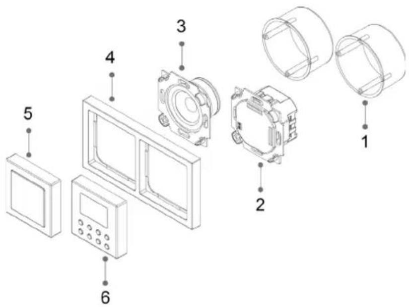
1 Recessed socket (not included in the scope of supply)
2 Radio unit
3 Speaker
4 Frame
5 Speaker cover
6 Radio operating unit
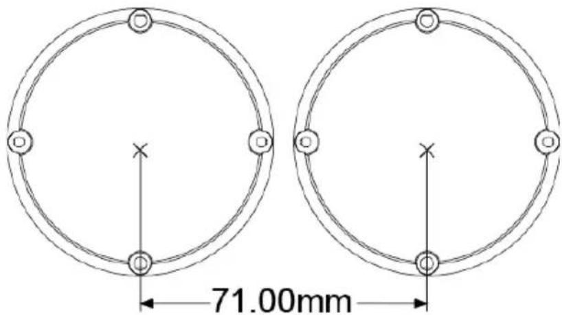
The DIGITRADIO UP1 can be mounted both horizontally and vertically.
With recessed sockets, ensure that the distance is correct according to the following illustration:
Speaker cable connection:
connect the blue speaker cable (+) to the speaker connection marked (+) on the radio unit and tighten using a suitable Phillips screwdriver.
Connect the brown speaker cable (-) to the speaker connection marked (-) on the radio unit and tighten using a suitable Phillips screwdriver.
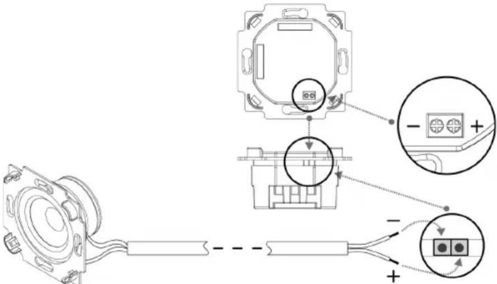
Power connection:
Connect the phase for domestic wiring (AC 100-240V, 50/60Hz) to the terminal marked (L) on the radio unit and tighten using a screwdriver.
Connect the neutral connector to the terminal marked (N) on the radio unit and tighten using a screwdriver.
The antenna is connected to the terminal marked (Antenna) on the radio unit.

Instead of the supplied antenna, the earthing cable (if there is one) can also be used as an antenna.

Ensure that only trained specialists are permitted to perform the power connection to domestic wiring. TechniSat accepts no liability for damage or injuries as a result of incorrect installation.

Ensure that, prior to connecting the radio unit to the mains network or the domestic wiring, the power is disconnected and secured from being switched on.

In order to completely switch off the radio if required, or to disconnect it from the mains network, it should be isolated using a separate switch. The phase should also be switchable.

Both units (speakers and radio unit) can then be attached to the existing recessed sockets and tightened. In doing so, depending on whether the units have been installed horizontally or vertically, ensure that the position of the plug contact strip on the radio unit for the display unit is correct.
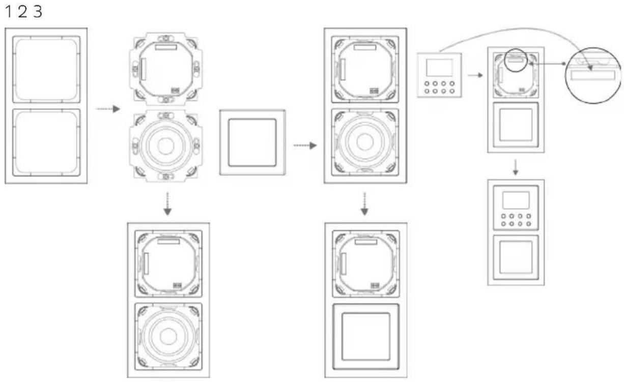
Horizontal layout:
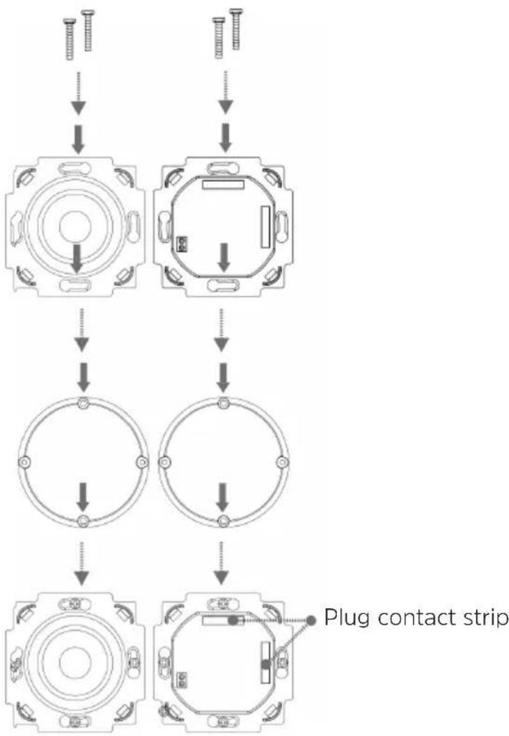
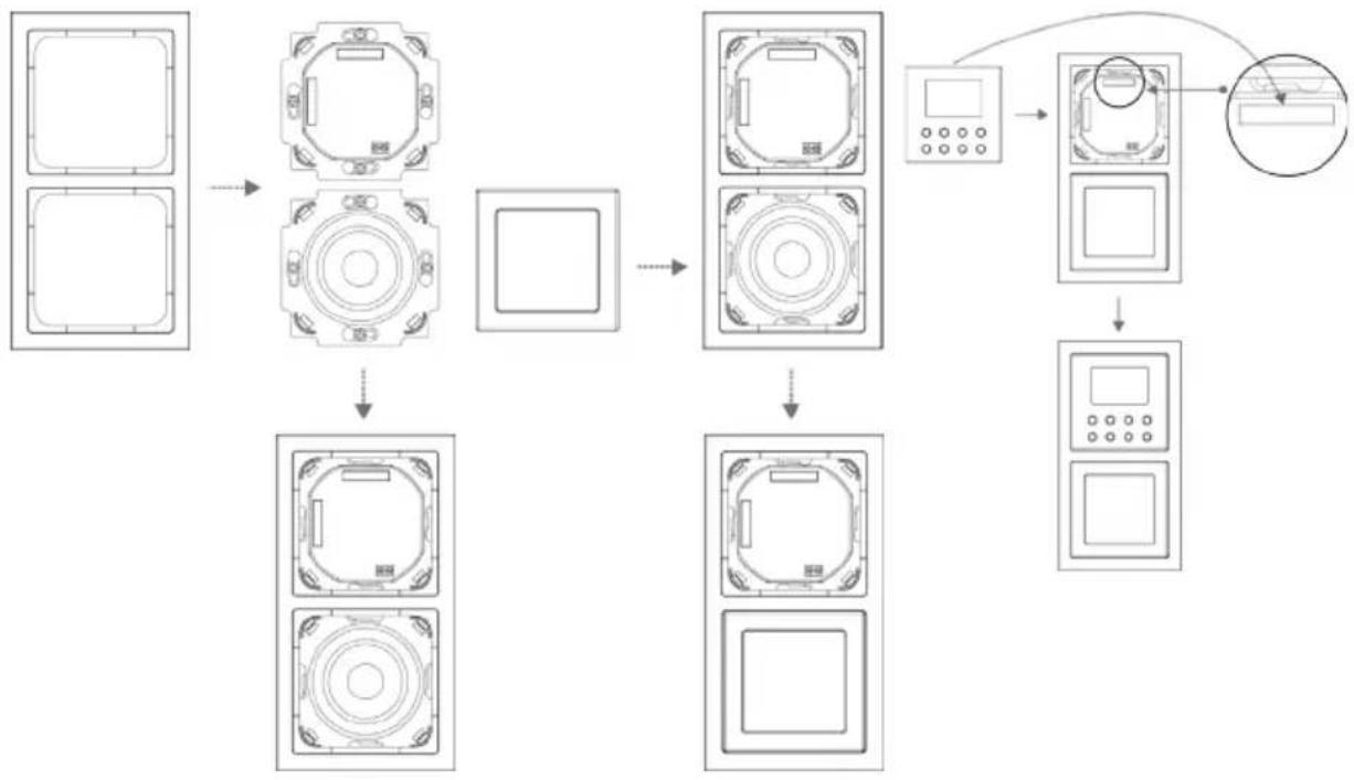
Vertical layout:
flowchart
graph TD
    A["Top screw"] --> B["Top view of socket"]
    B --> C["Top view of ring"]
    C --> D["Top view of circle"]
    D --> E["Top view of plug contact strip"]
    E --> F["Top view of socket"]
    F --> G["Top view of ring"]
    G --> H["Top view of circle"]
    H --> I["Top view of plug contact strip"]
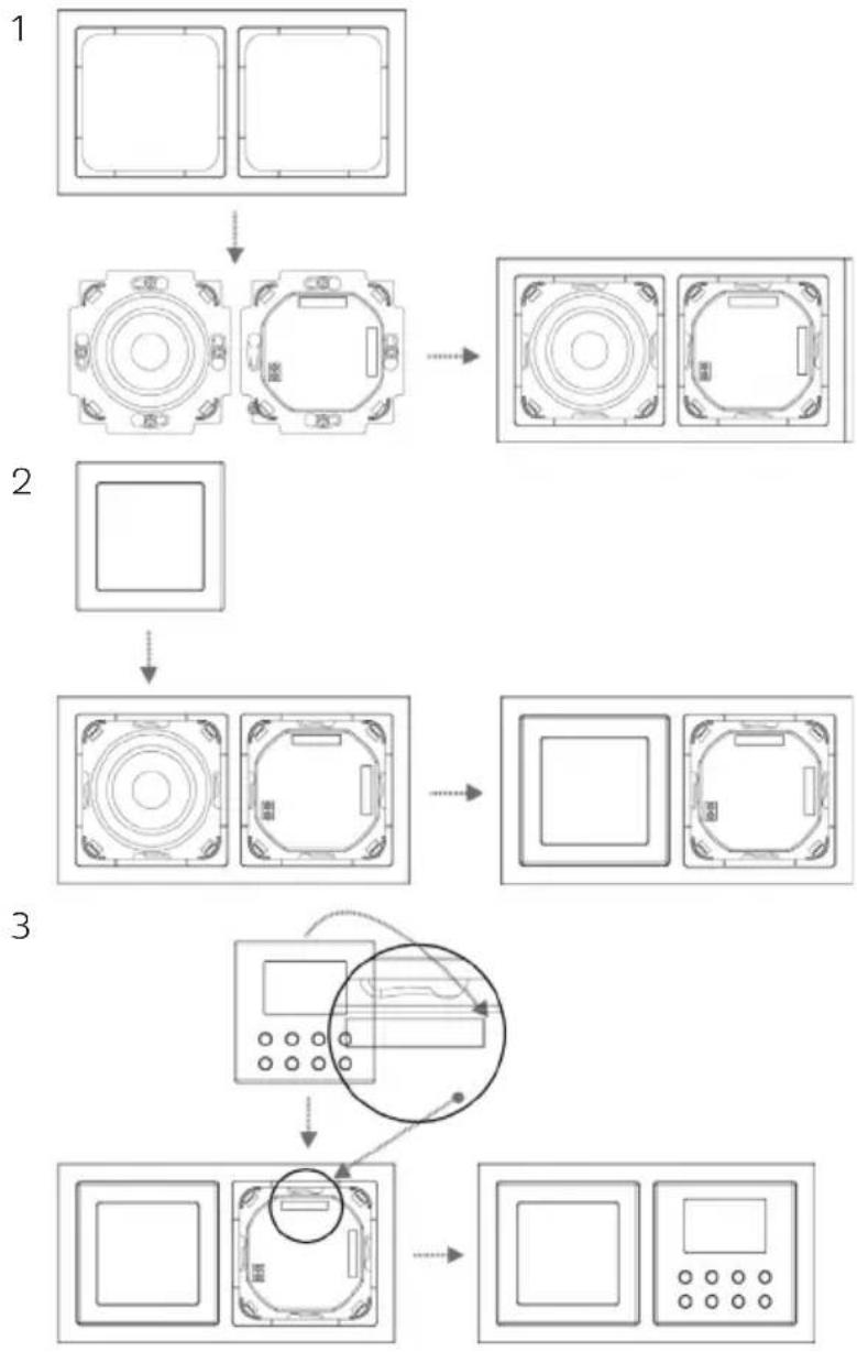
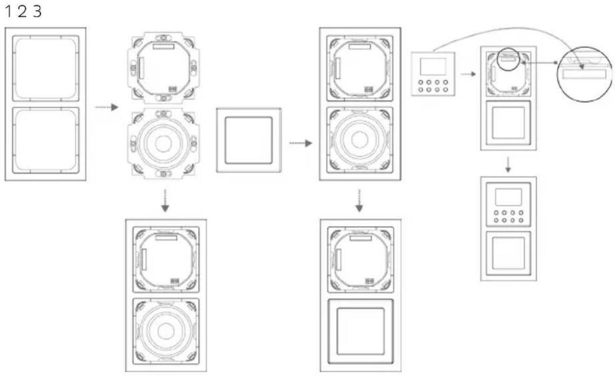
After successfully installing the radio unit and the speaker, the frame is attached by way of the speaker cover (Figure 1 - 2). In doing so, fit the speaker cover carefully by pressing gently on the speaker until it engages.
The display unit is then pressed carefully onto the radio unit, taking into account the alignment of the plug contact strip, until it engages (Figure 3).
Horizontal layout:
flowchart
graph TD
    A["Front View"] --> B["Top Panel"]
    B --> C["Top Panel with Right Side"]
    C --> D["Top Panel with Left Side"]
    D --> E["Top Panel with Right Side"]
    E --> F["Top Panel with Left Side"]
    F --> G["Top Panel with Right Side"]
    G --> H["Display Panel with Display and Control Panel"]
    H --> I["Display Panel with Left Side"]
    I --> J["Display Panel with Right Side"]
Vertical layout:
flowchart
graph TD
    A["Rectangular Unit 1"] --> B["Rectangular Unit 2"]
    B --> C["Rectangular Unit 3"]
    C --> D["Rectangular Unit 4"]
    D --> E["Rectangular Unit 5"]
    E --> F["Rectangular Unit 6"]
    F --> G["Rectangular Unit 7"]
    G --> H["Rectangular Unit 8"]
    H --> I["Rectangular Unit 9"]
    I --> J["Rectangular Unit 10"]
    J --> K["Rectangular Unit 11"]
    K --> L["Rectangular Unit 12"]
    L --> M["Rectangular Unit 13"]
    M --> N["Rectangular Unit 14"]
    N --> O["Rectangular Unit 15"]
    O --> P["Rectangular Unit 16"]
    P --> Q["Rectangular Unit 17"]
    Q --> R["Rectangular Unit 18"]
    R --> S["Rectangular Unit 19"]
    S --> T["Rectangular Unit 20"]
    T --> U["Rectangular Unit 21"]
    U --> V["Rectangular Unit 22"]
    V --> W["Rectangular Unit 23"]
Mode d'emploi
DIGITRADIO UP 1
1.2.2 Élimination....40
natural_image
Symbol of a trash bin with crossed lines indicating no waste or discharge (no text or labels)natural_image
Two electronic device components: a circular switch with labeled terminals A and B, and a black speaker grille (no text or symbols beyond labels)flowchart
graph TD
    A["Raw screw"] --> B["Internal component with circular opening"]
    B --> C["Circular component with central hub"]
    C --> D["Internal component with circular ring and mounting holes"]
    D --> E["Bande de contacts à fiche"]
    E --> F["Final component with circular end caps and mounting holes"]
flowchart
graph TD
    A["Front View"] --> B["Top Panel"]
    B --> C["Top Panel with Right-angle indicators"]
    C --> D["Top Panel with Right-angle indicators"]
    D --> E["Top Panel with Right-angle indicators"]
    E --> F["Top Panel with Right-angle indicators"]
    F --> G["Top Panel with Right-angle indicators"]
    G --> H["Display Panel with Display and Control knob"]
    H --> I["Display Panel with Display and Control knob"]
123
flowchart
graph TD
    A["Front View"] --> B["Top Panel"]
    B --> C["Square Box"]
    C --> D["Top Panel"]
    D --> E["Bottom Panel"]
    E --> F["Top Panel"]
    F --> G["Control Panel"]
    G --> H["Display Interface"]
    H --> I["Control Panel"]
    I --> J["Control Panel"]
    style A fill:#f9f,stroke:#333
    style B fill:#ccf,stroke:#333
    style C fill:#cfc,stroke:#333
    style D fill:#fcc,stroke:#333
    style E fill:#cff,stroke:#333
    style F fill:#ffc,stroke:#333
    style G fill:#cfc,stroke:#333
    style H fill:#fcc,stroke:#333
    style I fill:#ffc,stroke:#333
    style J fill:#cfc,stroke:#333
7.1.2 Stream audio....79
7.2 Ricezione DAB+ (Digital Radio)....79

natural_image
Two black-and-white diagrams showing crossed lines and radiating lines, no text or symbols present.
natural_image
Symbol of a trash bin with crossed lines indicating no waste or restriction, and a solid black rectangle below (no text or symbols)
natural_image
Close-up of a device component with labeled pins (A, B) and a speaker grille, shown from two views: left for front view, right for side view.Consumo elettrico in standby: < 1W
flowchart
graph TD
    A["Front View"] --> B["Top Panel"]
    B --> C["Top Panel with Right-angle indicators"]
    C --> D["Top Panel with Right-angle indicators"]
    D --> E["Top Panel with Right-angle indicators"]
    E --> F["Top Panel with Right-angle indicators"]
    F --> G["Display Panel with Display and Control Panel"]
    G --> H["Display Panel with Display and Control Panel"]

flowchart
graph TD
    A["Rectangular Unit 1"] --> B["Rectangular Unit 2"]
    B --> C["Rectangular Unit 3"]
    C --> D["Rectangular Unit 4"]
    D --> E["Rectangular Unit 5"]
    E --> F["Rectangular Unit 6"]
    F --> G["Rectangular Unit 7"]
    G --> H["Rectangular Unit 8"]
    H --> I["Rectangular Unit 9"]
    I --> J["Rectangular Unit 10"]
    J --> K["Control Panel"]
    K --> L["Rectangular Unit 11"]
    L --> M["Rectangular Unit 12"]
    M --> N["Rectangular Unit 13"]
Handleiding
DIGITRADIO UP 1
7.1.2 Audiostream....111
7.2 DAB+ (Digital Radio) ontvangst....111
7.2.8 Volume regelen (DRC)....113

natural_image
Two crossed-out diagrams showing a fence with smoke and a sun, no text or symbols present.
natural_image
Symbol of a trash bin with crossed lines indicating no waste or discharge (no text or labels)
natural_image
Two electronic device components: a circular switch with labeled terminals A and B, and a black speaker grille (no text or symbols beyond labels)7.2.8 Volume regelen (DRC)
1 Inbouwcontactdozen (niet inbegrepen)
2 Radio-unit
3 Luidsprekers
4 Frame
5 Luidsprekerafdekking
6 Bedieningseenheid radio
Stroomaansluiting:
flowchart
graph TD
    A["Start"] --> B["Assembly of a circular component"]
    B --> C["Concentrated circular part with inward arrow"]
    C --> D["Contact strip with connector"]
    D --> E["Final assembly with directional arrows indicating movement"]
flowchart
graph TD
    A["Front View"] --> B["Top Panel"]
    B --> C["Top Panel with Box"]
    C --> D["Top Panel with Box"]
    D --> E["Top Panel with Box"]
    E --> F["Top Panel with Box"]
    F --> G["Top Panel with Box"]
    G --> H["Display Panel with Display and Control Panel"]
    H --> I["Display Panel with Display and Control Panel"]
Verticale positie
123

flowchart
graph TD
    A["Front View"] --> B["Top Panel"]
    B --> C["Square Box"]
    C --> D["Top Panel"]
    D --> E["Bottom Panel"]
    E --> F["Top Panel"]
    F --> G["Control Panel"]
    G --> H["Display Interface"]
    H --> I["Control Panel"]
    I --> J["Control Panel"]
    style A fill:#f9f,stroke:#333
    style B fill:#ccf,stroke:#333
    style C fill:#cfc,stroke:#333
    style D fill:#fcc,stroke:#333
    style E fill:#cff,stroke:#333
    style F fill:#ffc,stroke:#333
    style G fill:#cfc,stroke:#333
    style H fill:#fcc,stroke:#333
    style I fill:#ffc,stroke:#333
    style J fill:#cfc,stroke:#333
Brukerveiledning
DIGITRADIO UP 1
Innfelt DAB+/FM-radio med Bluetooth
Innholdsfortegnelse
1 Innledning....134
8.5 Kanalsøk-innstilling....146
8.6 Mono/Stereo-innstilling....147
8.7 Lagre en FM-kanal på en minneposisjon....147
8.8 Hente en lagret FM-kanal....147
8.9 Skrive over / tømme en minneposisjon....147
9 Bluetooth....147
9.1 Pare en enhet.... 148
9.2 Spille over Bluetooth....148
natural_image
Symbol of a trash bin with crossed lines indicating no waste or restriction, and a solid black rectangle below (no text or symbols)i Informasjon om avfallshändtering:
natural_image
Close-up of a white electronic device with labeled ports A and B, alongside a black speaker grille (no text or symbols beyond labels)8.6 Mono/Stereo-innstilling
Trykk lenge på Info/Menu og velg menypunkt [Mono/Stereo-innstilling] med knappene << eller >>.
Trykk på Enter.
Velg menypunkt [Stereo mulig] eller [Kun mono] med << oder >>.
Bekreft med Enter.
Siden DIGITRADIO UP1 er en monoradio, har denne innstillingen bare innflytelse på mottaksstyrken til kanalen.
11 Systeminnstillinger
Alle innstillinger i dette punktet gjelder i både DAB+/FM og Bluetooth-drift.
Strømtilkobling:
flowchart
graph TD
    A["Initial State: Screw"] --> B["Section 1: Circular Body with Top/Bottom Ring"]
    B --> C["Section 2: Circular Body with Top/Bottom Ring"]
    C --> D["Section 3: Circular Body with Top/Bottom Ring"]
    D --> E["Section 4: Circular Body with Top/Bottom Ring"]
    E --> F["Final Stikkontaktist: Arrow pointing to a circular body with center"]
    style A fill:#f9f,stroke:#333
    style F fill:#bbf,stroke:#333
flowchart
graph TD
    A["Front View"] --> B["Device Setup"]
    B --> C["Control Panel"]
    C --> D["Display Panel"]
    D --> E["Control Panel"]
    E --> F["Display Panel"]
    F --> G["Control Panel"]
    G --> H["Display Panel"]
    H --> I["Control Panel"]
    I --> J["Display Panel"]
    J --> K["Control Panel"]
    K --> L["Display Panel"]
    L --> M["Control Panel"]
    M --> N["Display Panel"]
    N --> O["Control Panel"]
    O --> P["Display Panel"]
    P --> Q["Control Panel"]
    Q --> R["Display Panel"]
    R --> S["Control Panel"]
    S --> T["Display Panel"]
    T --> U["Control Panel"]
    U --> V["Display Panel"]
    V --> W["Control Panel"]
    W --> X["Display Panel"]
    X --> Y["Control Panel"]
7.1.2 Audio stream....175
7.2 DAB+ (digital radio) modtagelse....175
15 Installation....187
1 Forord
natural_image
Symbol of a trash bin with crossed lines indicating no waste or discharge (no text or labels)natural_image
Two electronic device components: a circular switch with labeled terminals A and B, and a black speaker grille (no text or symbols beyond labels)Strømtislutning:
flowchart
graph TD
    A["Front View"] --> B["Top Panel"]
    B --> C["Top Panel with Control Button"]
    C --> D["Top Panel with Screen"]
    D --> E["Top Panel with Screen with Button"]
    E --> F["Top Panel with Screen with Display"]
    F --> G["Control Panel with Display and Button"]
    G --> H["Final Display Panel with Screen and Display"]
Vertikal anordning
123

flowchart
graph TD
    A["Front View"] --> B["Device Setup"]
    B --> C["Control Panel"]
    C --> D["Display Panel"]
    D --> E["Control Panel"]
    E --> F["Display Panel"]
    F --> G["Control Panel"]
    G --> H["Display Panel"]
    H --> I["Control Panel"]
    I --> J["Display Panel"]
    J --> K["Control Panel"]
    K --> L["Display Panel"]
    L --> M["Control Panel"]
    M --> N["Display Panel"]
    N --> O["Control Panel"]
    O --> P["Display Panel"]
    P --> Q["Control Panel"]
    Q --> R["Display Panel"]
    R --> S["Control Panel"]
    S --> T["Display Panel"]
    T --> U["Control Panel"]
    U --> V["Display Panel"]
    V --> W["Control Panel"]
    W --> X["Display Panel"]
    X --> Y["Control Panel"]
Instrukcja obsługi
DIGITRADIO UP 1
8 Tryb FM (UKF)....210

natural_image
Two black-and-white diagrams showing crossed lines and radiating lines, no text or symbols present.
natural_image
Symbol of a trash bin with crossed lines indicating no waste or restriction, and a solid black rectangle below (no text or symbols)natural_image
Close-up of a white electronic device with labeled ports A and B, shown in two views: one showing a green indicator light and black sensor, the other showing a black speaker grille (no text or symbols visible)flowchart
graph TD
    A["Front View"] --> B["Top Panel"]
    B --> C["Top Panel with Box"]
    C --> D["Top Panel with Box"]
    D --> E["Top Panel with Box"]
    E --> F["Top Panel with Box"]
    F --> G["Top Panel with Box"]
    G --> H["Display Panel with Display and Control Panel"]
    H --> I["Display Panel with Display and Control Panel"]
Pozycja pionowa:

flowchart
graph TD
    A["Rectangular Unit 1"] --> B["Square Unit"]
    B --> C["Rectangular Unit 2"]
    C --> D["Square Unit"]
    D --> E["Rectangular Unit 3"]
    E --> F["Rectangular Unit 4"]
    F --> G["Rectangular Unit 5"]
    G --> H["Control Panel"]
    H --> I["Rectangular Unit 6"]
    I --> J["Output Interface"]
Návod k obsluze
DIGITRADIO UP 1

natural_image
Two black-and-white pictograms: one with a crossed-out bar and smoke, the other with a sunburst (no text or symbols)
natural_image
Symbol of a trash bin with crossed lines indicating no waste, and a solid black rectangle below (no text or labels)
Pokyny k likvidaci:
Likvidace obalu:
natural_image
Close-up of a white electronic device with labeled ports A and B, alongside a black speaker grille (no text or symbols beyond labels)flowchart
graph TD
    A["Front View"] --> B["Top Panel"]
    B --> C["Top Panel with Control Button"]
    C --> D["Top Panel with Top Section"]
    D --> E["Top Panel with Top Section with Top Section"]
    E --> F["Top Panel with Top Section with Top Section"]
    F --> G["Control Panel with Display Panel"]
    G --> H["Control Panel with Display Panel"]
    H --> I["Control Panel with Display Panel"]
123

flowchart
graph TD
    A["Front View"] --> B["Device Setup"]
    B --> C["Control Panel"]
    C --> D["Display Panel"]
    D --> E["Control Panel"]
    E --> F["Display Panel"]
    F --> G["Control Panel"]
    G --> H["Display Panel"]
    H --> I["Control Panel"]
    I --> J["Display Panel"]
    J --> K["Control Panel"]
    K --> L["Display Panel"]
    L --> M["Control Panel"]
    M --> N["Display Panel"]
    N --> O["Control Panel"]
    O --> P["Display Panel"]
    P --> Q["Control Panel"]
    Q --> R["Display Panel"]
    R --> S["Control Panel"]
    S --> T["Display Panel"]
    T --> U["Control Panel"]
    U --> V["Display Panel"]
    V --> W["Control Panel"]
    W --> X["Display Panel"]
    X --> Y["Control Panel"]
Návod na obsluhu
DIGITRADIO UP 1
DAB+/FM podomietkové rádio s Bluetooth

Obsah
1 Predslov 262
natural_image
Symbol of a trash bin with crossed lines indicating no waste or discharge (no text or labels)
Pokyny pre likvidáciu:
Likvidácia balenia:
natural_image
Close-up of a device component with labeled parts (A, B) and a speaker grille view (no text or symbols beyond labels)flowchart
graph TD
    A["Front View"] --> B["Top Panel"]
    B --> C["Top Panel with Box"]
    C --> D["Top Panel with Box"]
    D --> E["Top Panel with Box"]
    E --> F["Top Panel with Box"]
    F --> G["Top Panel with Box"]
    G --> H["Display Panel with Display and Control Panel"]
    H --> I["Display Panel with Display and Control Panel"]
flowchart
graph TD
    A["Rectangular Unit 1"] --> B["Rectangular Unit 2"]
    B --> C["Rectangular Unit 3"]
    C --> D["Rectangular Unit 4"]
    D --> E["Rectangular Unit 5"]
    E --> F["Rectangular Unit 6"]
    F --> G["Rectangular Unit 7"]
    G --> H["Rectangular Unit 8"]
    H --> I["Rectangular Unit 9"]
    I --> J["Rectangular Unit 10"]
    J --> K["Control Panel"]
    K --> L["Rectangular Unit 11"]
    L --> M["Rectangular Unit 12"]
    M --> N["Rectangular Unit 13"]
- Contents
- Foreword 6
- Illustration and buttons....11
- Connection and assembly of the DIGITRADIO UP1 12
- Description of the DIGITRADIO UP1....13
- General device functions....13
- Menu operation....14
- DAB+ (digital radio) function.... 15
- FM mode....18
- Bluetooth....19
- Other functions.... 21
- System settings....23
- Cleaning 26
- Foreword
- Target group for this instruction manual
- Intended use
- Caution!
- Important information
- Caution - This identifies important information that must be observed to prevent device defects, data loss/misuse or undesired operation.
- Tip - This identifies information relating to the described function, as well as to another related function that may have to be taken into account, with reference to the corresponding section in the manual.
- Safety
- Disposal
- Disposal instructions:
- Legal notices
- Service instructions
- Connection and assembly of the DIGITRADIO UP1
- Description of the DIGITRADIO UP1
- Scope of delivery
- The special features of the DIGITRADIO UP1
- General device functions
- Switching on the device
- Switching off the device
- Changing to DAB+/FM/Bluetooth mode
- Adjusting the volume
- Retrieving displays
- Menu operation
- DAB+ (digital radio) function
- What is DAB+?
- Data compression
- Audio stream
- DAB+ (digital radio) reception
- Performing a complete scan
- Selecting stations
- Storing DAB+ stations on a memory slot
- Retrieving DAB+ stations from a memory slot
- Overwriting/deleting a station memory slot
- Signal intensity
- Manual setting
- Volume adjustment (DRC)
- Deleting inactive stations
- FM mode
- Switching on FM radio mode
- FM reception with RDS information
- Automatic station scan
- Manual station scan
- Scan setting
- Audio settings
- Saving FM stations to a memory slot
- Retrieving FM stations from a memory slot
- Overwriting/deleting a station memory slot
- Bluetooth
- Pairing a device
- Bluetooth playback
- Other functions
- Sleep timer
- Alarm
- Setting the alarm time
- Switching off the alarm after being woken
- Deactivating the alarm
- Equaliser
- System settings
- Time and date settings
- Manually setting the time/date
- Time update
- Setting the time format
- [24 hours]
- [12 hours]
- Setting the date format
- Display brightness
- Language
- Factory setting
- Software version
- Cleaning
- Troubleshooting
- Technical data
- Installation
- Horizontal layout:
- Vertical layout:
- Mode d'emploi
- Handleiding
- DIGITRADIO UP 1
- Volume regelen (DRC)
- Verticale positie
- Brukerveiledning
- Innholdsfortegnelse
- Innledning....134
- Bluetooth....147
- i Informasjon om avfallshändtering:
- Mono/Stereo-innstilling
- Systeminnstillinger
- Forord
- Vertikal anordning
- Instrukcja obsługi
- Tryb FM (UKF)....210
- Návod k obsluze
- Pokyny k likvidaci:
- Návod na obsluhu
- Obsah
- Predslov 262
- Pokyny pre likvidáciu:
Brand : TECHNISAT
Model : DigitRadio UP 1
Category : Radio