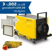
TAC 5000 - Air purifier TROTEC - Free user manual and instructions
Find the device manual for free TAC 5000 TROTEC in PDF.



| Product type | Air purifier |
| Brand | Trotec |
| Model | TAC 5000 |
| Dimensions (L × W × H) | 1252 × 690 × 926 mm |
| Weight | 113 kg |
| Power supply | 1/N/PE ~ 230 V / 50-60 Hz, 4,8 A |
| Motor power | 1270 W |
| Max. air flow | 4 500 m³/h |
| Recommended air flow (category H) | 2 500 m³/h |
| Sound level at 1 m | 68 dB(A) |
| Hose connection (suction/discharge) | Ø 400 mm |
| Dust category (DIN 60335-2-69) | H (transmission ≤ 0,005 %) |
| Filter surface H13 - Local size | 170 m³ / 18 m² |
| Power cable length | 2,5 m (H05RR-F) |
| Transport system | Swivel castors with brake, fork lift openings |
| Main functions | Air purification, negative pressure maintenance, Flowmatic, Vario-Shift |
| Maintenance | Casing cleaning, filter replacement, lubrication of telescopic rails |
| Safety | Surge protection, emergency stop, filter monitoring |
| Spare parts | Available (references in the manual) |
| Optional accessories | Conductive castors, fixed castors, fork openings |
Frequently Asked Questions - TAC 5000 TROTEC
User questions about TAC 5000 TROTEC
0 question about this device. Answer the ones you know or ask your own.
Ask a new question about this device
Download the instructions for your Air purifier in PDF format for free! Find your manual TAC 5000 - TROTEC and take your electronic device back in hand. On this page are published all the documents necessary for the use of your device. TAC 5000 by TROTEC.
USER MANUAL TAC 5000 TROTEC

TAC 5000
https://hub.trotec.com/?id=42770
Sicherheit
Information on the use of these instructions 2
Safety 2
Information about the device. 4
Transport and storage. 5
Assembly and start-up 6
Operation 9
Available accessories. 10
Errors and faults. 10
Maintenance 11
Disposal 12
Technical annex. 13
EU Declaration of Conformity (original) 31
Information on the use of these instructions
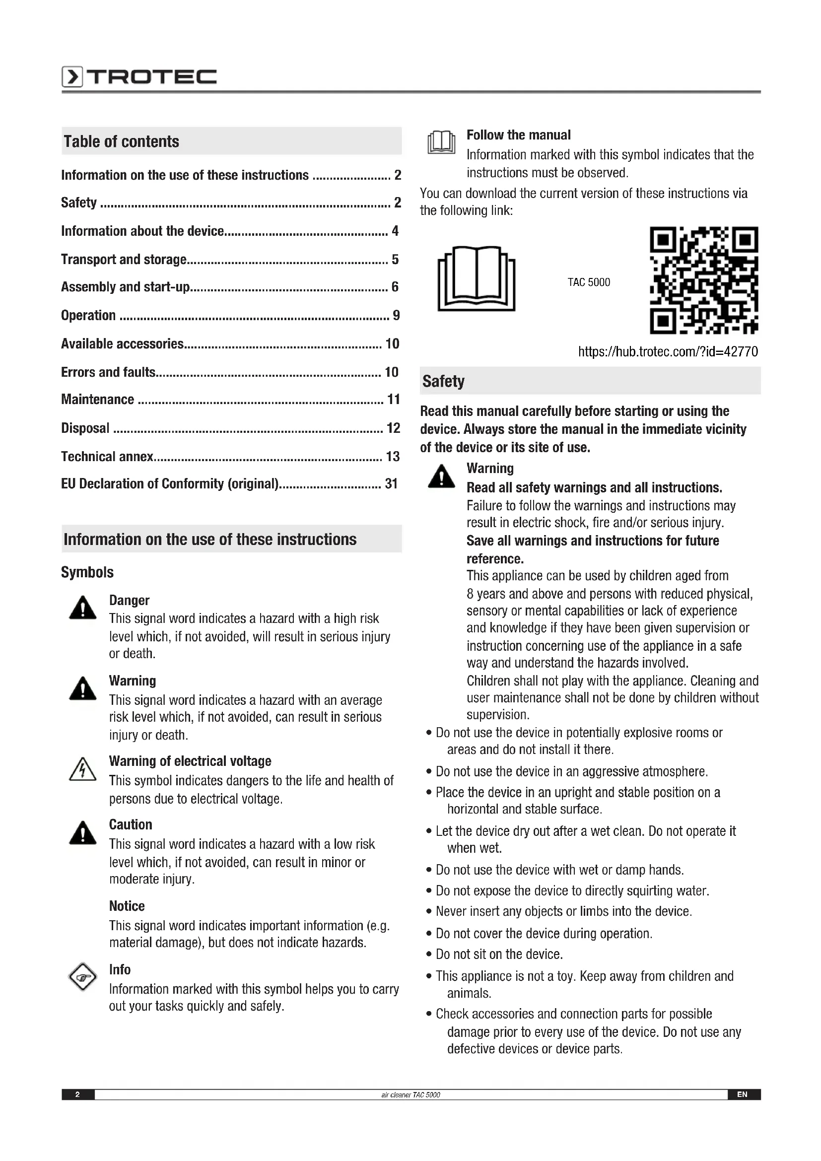
Symbols

Danger
This signal word indicates a hazard with a high risk level which, if not avoided, will result in serious injury or death.

Warning
This signal word indicates a hazard with an average risk level which, if not avoided, can result in serious injury or death.

Warning of electrical voltage
This symbol indicates dangers to the life and health of persons due to electrical voltage.

Caution
This signal word indicates a hazard with a low risk level which, if not avoided, can result in minor or moderate injury.
Notice
This signal word indicates important information (e.g. material damage), but does not indicate hazards.

Info
Information marked with this symbol helps you to carry out your tasks quickly and safely.

Follow the manual
Information marked with this symbol indicates that the instructions must be observed.
You can download the current version of these instructions via the following link:


TAC 5000
https://hub.trotec.com/?id=42770
Safety
Read this manual carefully before starting or using the device. Always store the manual in the immediate vicinity of the device or its site of use.

Warning
Read all safety warnings and all instructions.
Failure to follow the warnings and instructions may result in electric shock, fire and/or serious injury.
Save all warnings and instructions for future reference.
This appliance can be used by children aged from 8 years and above and persons with reduced physical, sensory or mental capabilities or lack of experience and knowledge if they have been given supervision or instruction concerning use of the appliance in a safe way and understand the hazards involved.
Children shall not play with the appliance. Cleaning and user maintenance shall not be done by children without supervision.
- Do not use the device in potentially explosive rooms or areas and do not install it there.
- Do not use the device in an aggressive atmosphere.
- Place the device in an upright and stable position on a horizontal and stable surface.
- Let the device dry out after a wet clean. Do not operate it when wet.
- Do not use the device with wet or damp hands.
- Do not expose the device to directly squirting water.
- Never insert any objects or limbs into the device.
- Do not cover the device during operation.
- Do not sit on the device.
- This appliance is not a toy. Keep away from children and animals.
-
Check accessories and connection parts for possible damage prior to every use of the device. Do not use any defective devices or device parts.
-
Ensure that all electric cables outside of the device are protected from damage (e.g. caused by animals). Never use the device if electric cables or the power connection are damaged!
- The mains connection must correspond to the specifications in the Technical annex.
- Insert the mains plug into a properly fused mains socket.
- Observe the technical data when selecting extensions to the power cable. Completely unroll the extension cable. Avoid electrical overload.
- Before carrying out maintenance, care or repair work on the device, remove the mains plug from the mains socket. Hold onto the mains plug while doing so.
- Switch the device off and disconnect the power cable from the mains socket when the device is not in use.
- Do not under any circumstances use the device if you detect damages on the mains plug or power cable. If the supply cord is damaged, it must be replaced by a special cord or assembly available from the manufacturer or its service agent. Defective power cables pose a serious health risk!
- When positioning the device, observe the minimum distances from walls and other objects as well as the storage and operating conditions specified in the Technical annex.
- Make sure that the air inlet and outlet are not obstructed.
- Make sure that there are no loose items or dirt located in the immediate surroundings of air inlet and air outlet.
- Do not remove any safety signs, stickers or labels from the device. Keep all safety signs, stickers and labels in legible condition.
- Make sure that the suction side is kept free of dirt and loose objects.
- Dispose of replaced filters properly, especially after filtering substances hazardous to health.
- Never use the device as storage place or footstep.
Intended use
Only use the device to clean atmospheric air from non-conducting and non-combustible dusts, fogs or suspended matter whilst using the appropriate filter classes and adhering to the technical data.
The device is intended to be used in commercial areas.
Any use other than the intended use is regarded as misuse.
Reasonably foreseeable misuse
- Do not place the device on wet or flooded ground.
- Do not place any objects, e.g. clothing, on the device.
- Do not use outdoors.
- Do not use the device to siphon off vapours or fluids.
- Do not make any unauthorised modifications, alterations or structural changes to the device.
Personnel qualification
People who use this device must:
have basic knowledge of how to safely handle electrical equipment.
have read and understood the instructions, especially the Safety chapter.
Electrically skilled person
Electrically skilled personnel must be able to read and understand electric circuit diagrams, to put electrical systems into service and to maintain them, to wire control cabinets, to ensure the functionality of electrical components and to identify possible hazards from electrical and electronic systems.
Instructed person
Instructed persons have been informed of the tasks they were entrusted with as well as of potential hazards resulting from inappropriate behaviour. They are allowed to operate and transport the device and perform simple maintenance activities (cleaning the housing, cleaning the fan).
The device is to be maintained and looked after by instructed personnel.
Residual risks

Warning of electrical voltage
Work on the electrical components must only be carried out by an authorised specialist company!

Warning of electrical voltage
Before any work on the device, remove the mains plug from the mains socket!
Do not touch the mains plug with wet or damp hands. Hold onto the mains plug while pulling the power cable out of the mains socket.

Caution
Risk of injury from parts being whirled up!
Before switching the device on, make sure that there are no loose parts (clothing, hair ...) located near the air inlet or outlet!
Notice
Observe the overvoltage protection.
The device comes equipped with an overvoltage protection. When checking for electrical safety, please bear in mind that the test voltage has to be reduced to 250V .
Notice
Do not operate the device without an air filter inserted into the air inlet!
Without the air filter, the inside of the device will be heavily contaminated. This can reduce the performance and result in damage to the device.
Notice
Do not use abrasive cleaners or solvents to clean the device.
Behaviour in the event of an emergency
- Switch the device off.
- Disconnect the device from the mains by removing the mains plug from the socket. When doing so, be sure to hold the plug, not the cable.
- Do not reconnect a defective device to the mains.
Information about the device
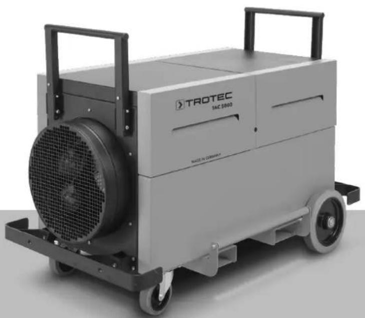
Device description
Air cleaners are used to filter the room air. On building sites and renovation areas high concentrations of dust can arise, for instance when using angle grinders or during blasting, chiselling or demolition operations as well as when mixing dry mortar or tile cement.
Depending on the inserted filter, the air cleaners of the TAC series serve to eliminate various dusts, e.g. from asbestos, building rubble, quartz, flour, wood, etc., but also mould spores, paint particles and mineral fibres in the air, possibly arising during the above-mentioned operations.
This dust is to be vacuumed off as close as possible to the point of origin in order to reduce the pollution of the breathing air to a minimum. Depending on the used filter quality it is permissible to employ the device for the separation of quartziferous mineral dusts, wood dust, lead-containing dusts, artificial mineral fibres or high-temperature fibres.
The air cleaner comes equipped with a sensor-supported Flowmatic control for the automatic retention of the preselected air volume.
Application as vacuum generator for mould remediation and asbestos abatement is also a possibility. In case of other hazardous substances there are additional requirements; hence observe the corresponding Technical Rules for Hazardous Substances (TRGS) or the country-specific regulations.
The device is suited for:
- producing a vacuum in a room, e.g. in heavily contaminated spaces;
- air purification in workspaces via air circulation, e.g. indoor building sites, workshops etc.;
- producing overpressure in a room, e.g. cleanroom;
- supplying filtered fresh air.
The device is structured as follows:
- housing with stacking aid
- adjustable fan for air transport
- filter monitoring for air volume flow
The device may be equipped with various filters. It provides the user with the possibility of configuring both the filter quality and the filter chain arrangement for the respective field of application. The filters must be selected according to the area of application.
The device is approvable for asbestos abatement as per TRGS 519, dust class H.

Info
The filters are not included in the scope of delivery! Choose the filters according to the area of application from our filter range. Insert the selected filters prior to initial start-up.
Device depiction
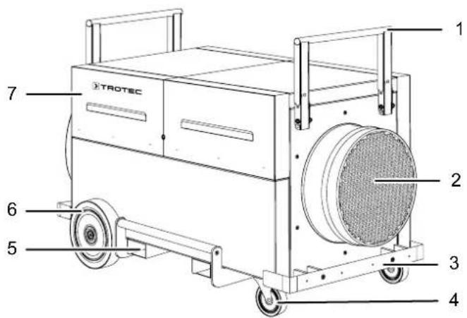
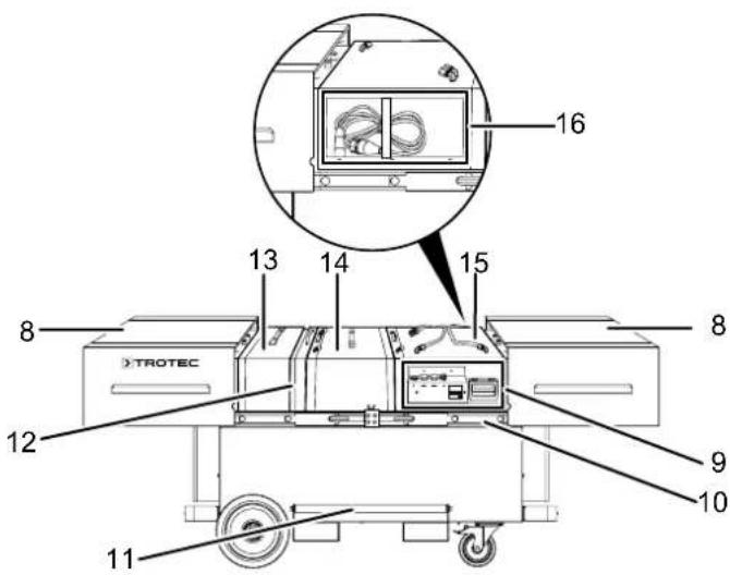
| No. Designation |
| 1 stacking / push handle |
| 2 air intake opening with hose / pipe connection |
| 3 shock protection |
| 4 swivel castor with brake (rubber, non-marking) |
| 5 forklift pocket |
| 6 wheel (rubber, non-marking) |
| 7 hinged cover |
| 8 sliding cover |
| 9 control panel |
| 10 telescopic slide |
| 11 lifting handle |
| 12 tensioning frame |
| 13 pre-filter box |
| 14 main filter box |
| 15 fan box |
| 16 cable storage compartment |
Transport and storage
Notice
If you store or transport the device improperly, the device may be damaged.
Note the information regarding transport and storage of the device.
Transport
Before transporting the device, observe the following:
The device is switched off.
- The device is disconnected from the mains and the mains plug has been disconnected.
After transporting the device, proceed as follows:
The device has been set up in an upright and stable position.
Storage
When the device is not being used, observe the following storage conditions:
- Store the device in a dry location and protected from frost and heat.
- Store the device in an upright position where it is protected from dust and direct sunlight.
- If required, use a cover to protect the device from invasive dust.
Assembly and start-up
Scope of delivery
- 1 x Device
- 1 x Manual
Unpacking the device

Warning
There is a danger of suffocation for children due to packaging material! Keep packaging films and parts away from children. There is a risk of death due to suffocation.
- Open the cardboard box and take the device out.
- Completely remove the packaging.
- Fully unwind the power cable. Make sure that the power cable is not damaged and that you do not damage it during unwinding.
Assembly
Sliding covers
Please proceed as follows to open the sliding covers (8):
- Pull the stacking handles (1) up and fold them down.
- Pull the sliding covers (8) outwards with a jerk and shove it apart all the way to the stop.
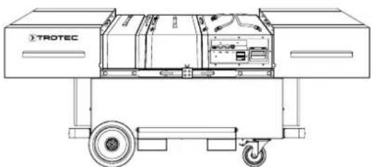
Please proceed as follows to close the sliding covers (8):
- Push the sliding covers (8) together until they lock in place.
- Tilt the stacking handles (1) up and lock them in place.
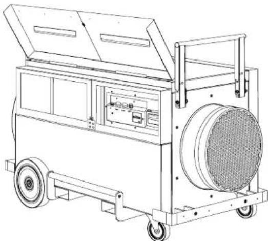
Hinged covers
In order to open the hinged covers (7), swing them up until they are held in place by the magnets.
Proceed in reverse order to close the hinged covers.
Inserting the filters

Info
The filters are not included in the scope of delivery! Choose the filters according to the area of application from our filter range. Insert the selected filters prior to initial start-up.
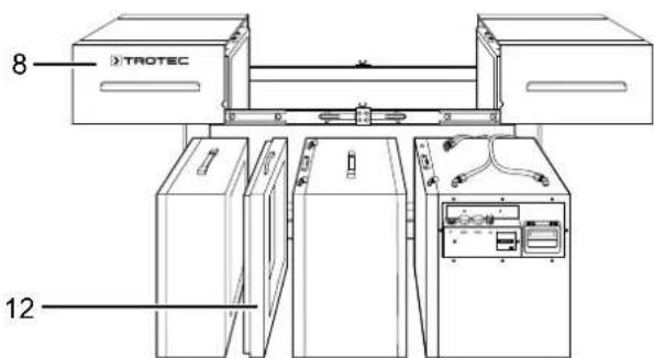
Prior to start-up the filter chain of the device must be configured according to the desired field of application. For this, two filter boxes are available.
- Open the sliding cover (8).
- Pull out the tensioning frame (12) towards the top.
- Remove further boxes from the device as required.
Notice
For all filter installations always observe the correct flow direction according to the direction of the air current (air flow direction: from back to front)! Note that the main filter is locked at the bottom of the housing. The lock is located under the tensioning frame (12) and the prefilter (13).
Configuration
The TAC series is equipped with Vario-shift function. This means that the filter elements can be variably arranged for all application scenarios and in line with the regulations.
- The building site configuration for the separation of suspended matter as per DIN EN 60335-2-69 to dust class H; main priority with these applications has the filtering of dust particles dangerous to health, to some extent even carcinogenic. The entire filter ladder has to be operated at underpressure to prevent unfiltered air from escaping even in case of leakages when sucking off these dusts. Which means that the fan is to be positioned downstream of the main filter! Both are to be braced using tensioning elements on the unit side so that the high-efficiency particulate air filter does not come into contact with polluted air at the outlet during the entire operating time and the risk of leaks is minimized!
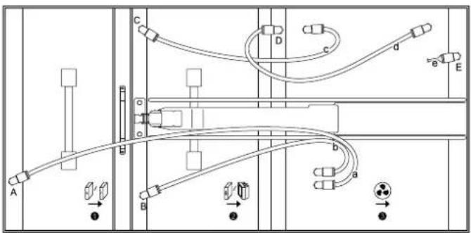
- The cleanroom configuration for the separation of suspended matter as per DIN EN 1822-1:1998 to filter class H14 (in case of a substantially reduced air volume filters with higher filtration efficiencies are also an option); as a rule, air from a polluted area is fed to a cleanroom, e.g. as fresh air supply. The applicable regulations usually demand that the filtered air may only come into contact with a clean air pipe/duct operated at overpressure. Therefore, the fan is to be positioned upstream of the main filter! Here, too, the elements are to be braced as stated for the building site configuration!
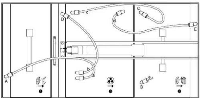
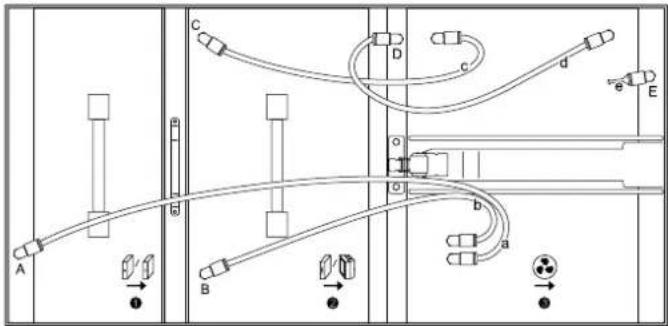
- Generic configuration for air purification applications filtering coarse dust or fine particulates as per DIN EN 779 to filter class F9; these applications do not require any particular fan position. For reasons of simplified filter change management it is recommended for the fan to be the last element to be incorporated and braced.
Notice
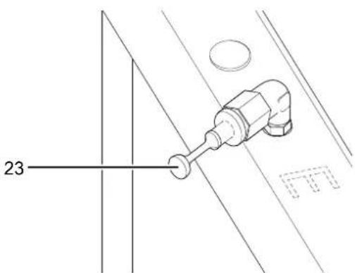
For the individual configurations it is important to make sure that the air hoses (marked a, b, c, d) and the dummy plug (23) are connected to the measuring points (marked A, B, C, D, E) according to the box arrangement (pre-filter = 1 + main filter = 2+ fan = 3 ). Otherwise the filter monitoring will not be working!
Example:
Start-up
When positioning the device, observe the minimum distance from walls or other objects as described in the chapter Technical annex.
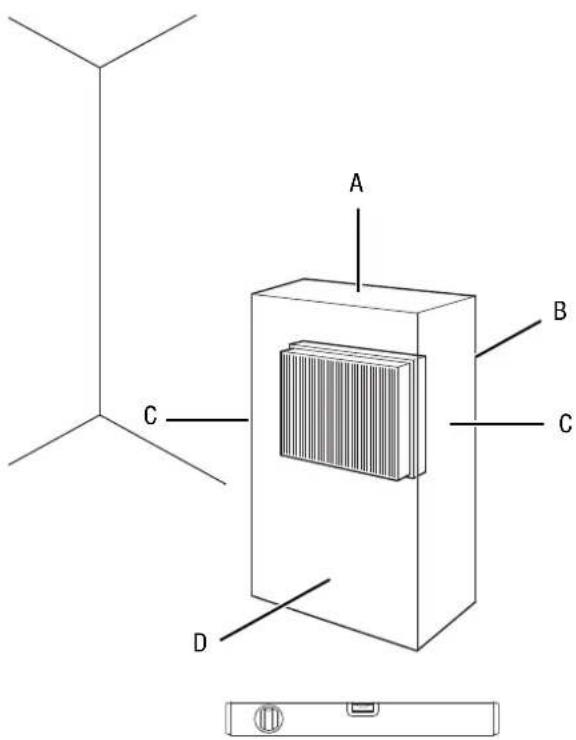
- Before restarting the device, check the condition of the power cable. If there are doubts as to the sound condition, contact the customer service.
- Place the device in an upright and stable position on a horizontal and stable surface.
- Do not create tripping hazards when laying the power cable or other electric cables, especially when positioning the device in the middle of the room. Use cable bridges.
- Ensure that the extension cables are completely unrolled.
- Position the device near the source of air contamination.
- When positioning the device, keep a sufficient distance to heat sources.
- Make sure that no curtains or other objects interfere with the air flow.
- Make sure that the air inlet and outlet are not obstructed.
Installation of the device in the room, the air of which is to be purified
- When positioning the device, make sure it is located in the centre of the room the air of which is to be cleaned. Alternatively, you can also position the device near the source of air contamination.
- Prior to operation you have to ensure that the filters have been installed in the device as desired.
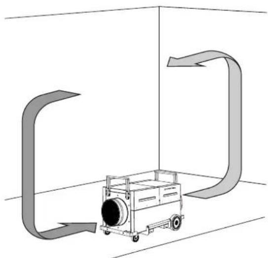
- The device works in recirculation mode, this means that the contaminated air enters the air cleaner via the air inlet opening and is blown out through the air outlet opening in purified state.
Air purification in sealed off area via air circulation:
Installation of the device outside of the room, the air of which is to be purified
The device can be connected in either recirculation or ventilation mode.
- In recirculation mode, the air to be cleaned is led via a hose from the room into the air inlet opening of the device. The purified air is fed through another hose from the air outlet opening and back into the room.
- In ventilation mode, the air to be cleaned is led via a hose from the room into the air inlet opening of the device. This creates a slight negative pressure in the room. Clean, fresh air flows in from outside.
Installation variants for maintaining the pressure:
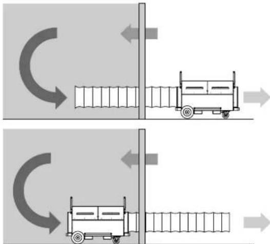
When connecting hoses, the following must be observed:
- The used pipes and hoses must be designed for the available static compression of the fans. They should preferably be laid in a straight line and at full length. 7.6m of air hose each can be connected to the air inlet and air outlet openings of the device.
- There ought to be a minimum distance of 1m between air inlet and air outlet opening.
Connecting the power cable
- Connect the mains plug to a properly secured socket.
Operation
Operating elements
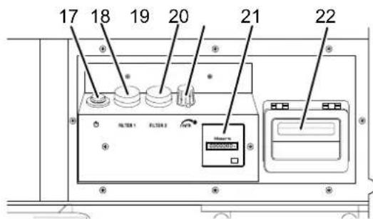
| No. | Designation Meaning | |
| 17 | Power button Switching the device on or off | |
| 18 | Filter 1 warning light Indication of required coarse or fine filter change | |
| 19 | Filter 2 warning light Indication of required HEPA or bag filter change | |
| 20 | Air volume control dial For setting the desired air volume | |
| 21 | Operating hours counter Indication of operating hours | |
| 22 | Flowmatic with display Indication of the air volume (volumetric flow) |
Switching the device on
- Make sure that neither the air inlet nor the air outlet opening is covered.
- Turn the Air volume control dial (20) counter-clockwise to the lowest level.
- Press the Power button (17). ⇒ The Power button (17) lights up.
Adjusting the air volume
By use of the stepless air volume control dial (20) you can adjust the fan speed and thus regulate the air volume conveyed by the device.
Shutdown

Warning of electrical voltage
Do not touch the mains plug with wet or damp hands.
- Switch off the device.
- Disconnect the device from the mains by removing the mains plug from the socket. When doing so, be sure to hold the plug, not the cable.
Available accessories

Warning
Only use accessories and additional equipment specified in the instructions.
Using insertion tools or accessories other than those specified in the instructions may cause a risk of injury.
| Designation Article number | |
| G4 Z-line filter / ISO coarse 75 % 7.160.000.448 | 7.160.000.449 |
| F7 pleated filter cartridge / ISO ePM10 75 % | |
| F7 bag filter / ISO ePM10 75 % 7.160.000.450 | 7.160.000.451 |
| H13 HEPA filter approved for dust class H | |
| G3 spray paint filter / ISO coarse 30 % | 7.160.000.452 |
| Activated carbon filter 7.165.005.000 | 6.100.001.212 |
| Air transport hose Tronect SP-T, length 7.6 m |
Errors and faults
The device has been checked for proper functioning several times during production. If malfunctions occur nonetheless, check the device according to the following list.
The device does not start:
- Check the power connection.
- Check the power cable and mains plug for damage.
- Check the on-site fusing.
- Wait for 10 minutes before restarting the device. If the device is not starting, have the electrics checked by a specialist company or by Trotec.
The device is loud or vibrates:
- Check whether the device is set up in a stable and upright position.
The device gets very warm, is loud or is losing power:
- Check the air inlet and air filter for dirt. Remove external dirt.
The device gives off an unpleasant odour:
- Smoke, e.g. dense tobacco smoke, odours and contaminations may be in the air. Ventilate the room.
The device still does not operate correctly after these checks:
Contact the manufacturer's customer service. If necessary, take the device to an authorised specialist electrical company or to the manufacturer for repair.
Maintenance
Activities required before starting maintenance

Warning of electrical voltage
Do not touch the mains plug with wet or damp hands.
- Switch the device off.
- Disconnect the device from the mains by removing the mains plug from the socket. When doing so, be sure to hold the plug, not the cable.

Warning of electrical voltage
Tasks which require the device to be opened must only be carried out by authorised specialist companies or by the manufacturer.
Notice
Observe the overvoltage protection.
The device comes equipped with an overvoltage protection. When checking for electrical safety, please bear in mind that the test voltage has to be reduced to 250 V.
Cleaning the housing
Clean the housing with a soft, damp and lint-free cloth. Make sure that no moisture enters the housing. Protect electrical components from moisture. Do not use any aggressive cleaning agents such as cleaning sprays, solvents, alcohol-based or abrasive cleaners to dampen the cloth.
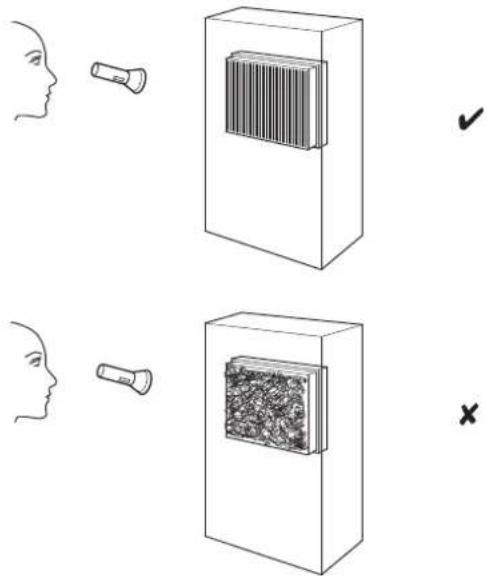
Visual inspection of the inside of the device for dirt
- Remove the air filters.
- Use a torch to illuminate the openings of the device.
- Check the inside of the device for dirt.
-
If you see a thick layer of dust, clean the inside of the device with a vacuum cleaner.
-
Reinsert the air filters.
Filter change
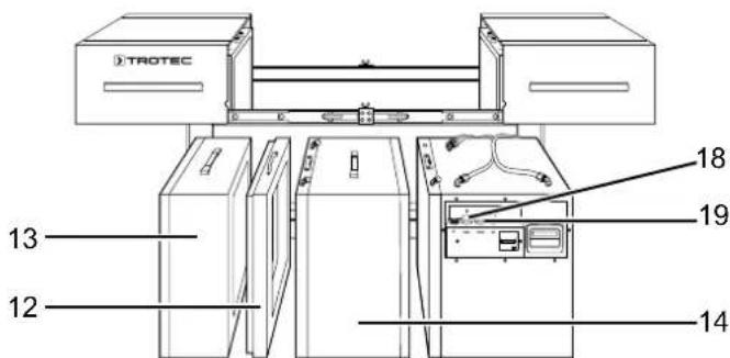
The filters must be replaced when the filter change warning light for filter 1 (18) or filter 2 (19) lights up during operation and an acoustic signal is emitted.
- Detach air hose A from the measuring point.
- Pull out the tensioning frame (12) towards the top.
- Pull the pre-filter box (13) out of the device in an upward motion and remove the filters from the box.
- If required, also loosen the clasp and the locking lever on the filter boxes.
- Disconnect the air hoses B and C from the measuring points.
- Move the main filter box (14) a little sideways.
- Pull the main filter box (14) out of the device in an upward motion and remove the filters from the box.
- For assembling the filter boxes please proceed in reverse order.
Lubricating the telescopic slides
The covers' telescopic slides (10) are to be lubricated after cleaning or as needed.
Disposal
Always dispose of packing materials in an environmentally friendly manner and in accordance with the applicable local disposal regulations.

The icon with the crossed-out wheeled bin indicates that this device and any associated components must not be disposed of with household waste at the end of their life, in accordance with the Waste Electrical and Electronic Equipment Directive (2012/19/EU) and national laws.
You will find collection points for free return of waste electrical and electronic equipment in your vicinity. The addresses can be obtained from your municipality or local administration. You can also find out about other return options that apply for many EU countries on the website https://hub.trotec.com/?id=45090. Otherwise, please contact an official recycling centre for electronic and electrical equipment authorised for your country. The separate collection of waste electrical and electronic equipment aims to enable the re-use, recycling and other forms of recovery of waste equipment as well as to prevent negative effects for the environment and human health caused by the disposal of hazardous substances potentially contained in the equipment.
Only for United Kingdom
According to Waste Electrical and Electronic Equipment Regulations 2013 (SI 2013/3113) (as amended) devices that are no longer usable must be collected separately and disposed of in an environmentally friendly manner.
Technical annex
Technical data
| Parameter Value | |
| Model TAC 5000 | |
| Article number 1,580,000,125 | |
| Max. air volume 4500 m | 3/h |
| Recommended amount of air for dust class H | 2500 m³/h |
| Room size | 170 m³ |
| with filter surface H13 | 18 m² |
| Dust class (as per DIN 60335-2-69) | dust class H (transmittance ≤ 0.005 %) for substances with a max. allowable concentration of ≤ 0.1 mg/m³, carcinogenic hazardous substances as per GefStoffV § 11 (Ordinance on Hazardous Substances), TRGS 905 or 906 (Technical Rules for Hazardous Substances), approvable for asbestos abatement as per TRGS 519 |
| Motor power 1270 W | |
| Power supply 1/N/PE ~ 230 V / 50-60 Hz | |
| Nominal current 4.8 A | |
| Connection cable CEE 7/7, cable length 2.5 m | rubber conduit (H05RR-F) length = 2.5 m |
| Air transport hose connector inlet/outlet side | 400 mm |
| Sound level (at a distance of 1 m) 68 dB(A) | |
| Dimensions (length x width x height) | 1252 x 690 x 926 mm |
| Weight 113 kg |
Recommendation for filter combinations specific to the application and corresponding room size suitability
| suitable for rooms sized up to 1) | |||
| Fields of application Filter combination m | 3 | m2 | |
| Coarse dust 2) (≤ 3 ACH6) G4 1200 480 | |||
| Fine particulates 3) (≤ 3 ACH6) | G4 + F7 to F9 | 600 | 240 |
| Suspended matter 4) (≤ 3 ACH6) | G4 + H13 | 150 | 60 |
| Hygienic areas 5) (≤ 3 ACH6) | G4 + H13 | 110 | 44 |
1) With an assumed room height of 3 m; 2) Typical coarse dust tasks: sawing, filing; 3) Typical fine dust tasks: restoration works with materials containing minerals or glass wool; 4) Typical suspended matter tasks: grinding, asbestos abatement or mould remediation, mineral dusts etc.; 5) H13 downstream; 6) Air exchange per hour
Optional equipment (upon request)
| Guiding wheels with pneumatic tyres, traceless |
| Trestle rollers (instead of guiding wheels) |
| Fork pockets for fork lifts |
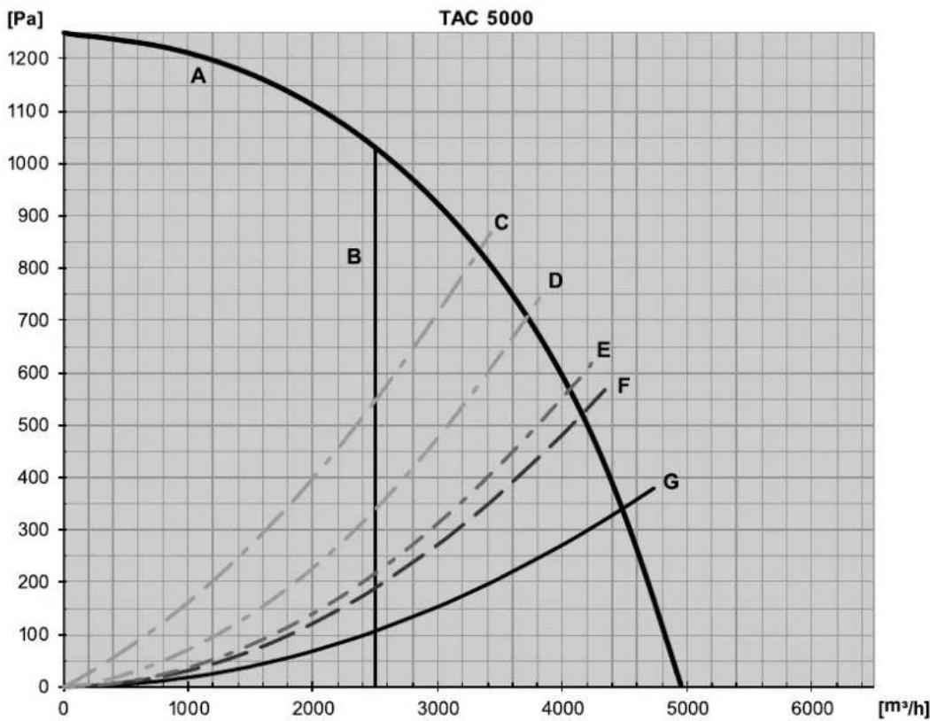
Performance chart
| A Fan | |
| B Recommended amount of air for dust class H | |
| C With G4-H13 filter combination (approval for dust class H) and air transport hose* | |
| D With G4-F7 filter combination and air transport hose* | |
| E With G4 filter and air transport hose* | |
| With spray paint filter and air transport hose* | |
| F Without filter, with air transport hose* | |
| * Connected to the pressure side, standard length 7.6 m, laid with one 90° arc. When the air hose is laid stretched and arc-free, an increase of air volume by up to 25% is possible! | |
Overview Info

The position numbers of the spare parts differ from those describing the positions of the components mentioned in these instructions.
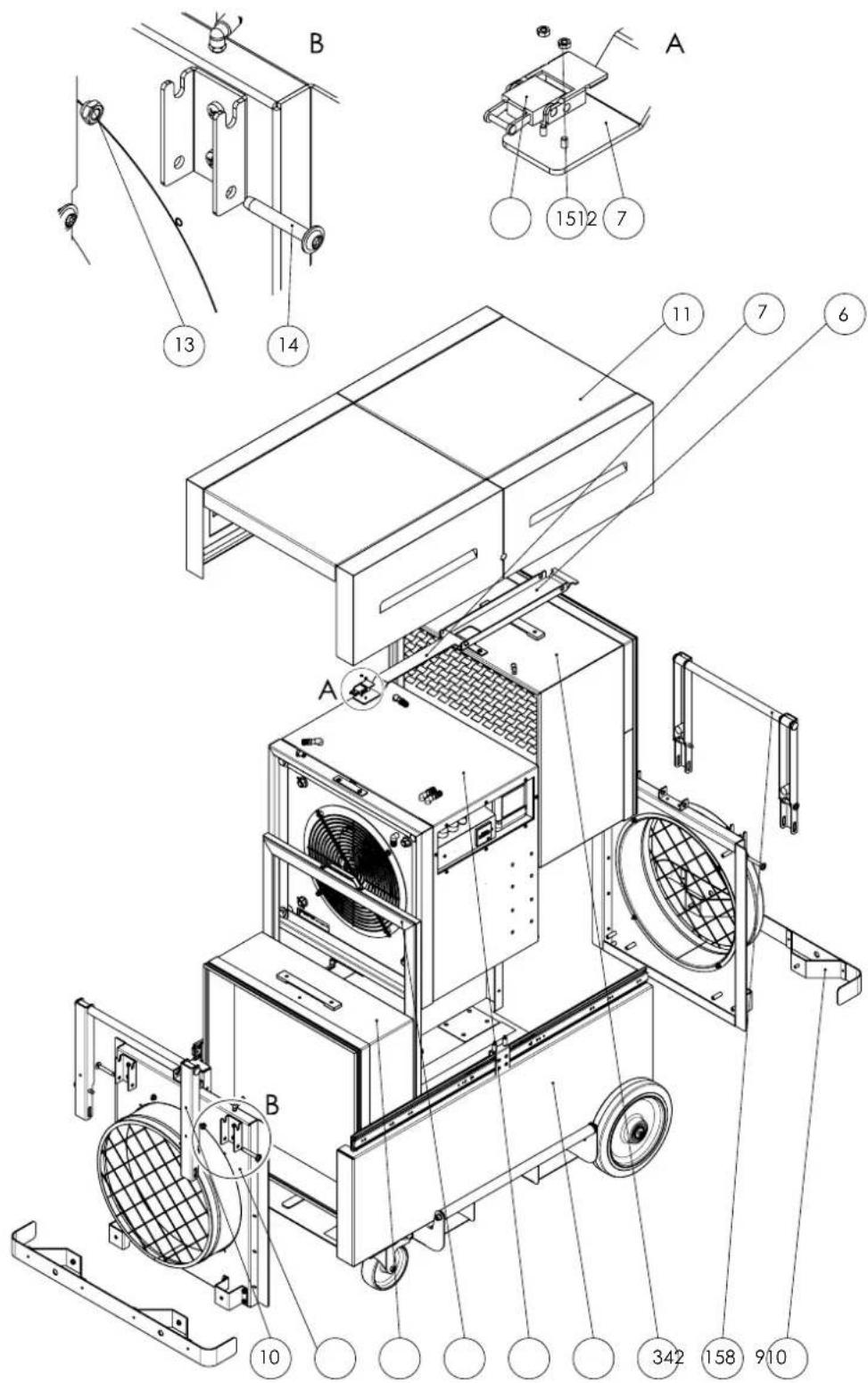
| No. Designation Article number | No. Designation Article number | ||||
| 1 | Basic housing ZAT0001045 9 Rear impact protection ZAT0001055 | ||||
| 2 | Prefilter ZAT0001167 10 Frame ZAT0001140 | ||||
| 3 | HEPA ZAT0001004 11 Cover ZAT0001062 | ||||
| 4 | Fan ZAT0001033 12 Spring tension element P10000615 | ||||
| 5 | Tension element ZAT0000975 13 Nut | P10000099 | |||
| 6 | Tension arm | P10003329 | 14 | Screw | P10001594 |
| 7 | Tension rod | P10003328 | 15 | Nut | P10001121 |
| 8 | Air outlet ZAT0001119 | ||||
Basic housing Info

The position numbers of the spare parts differ from those describing the positions of the components mentioned in these instructions.
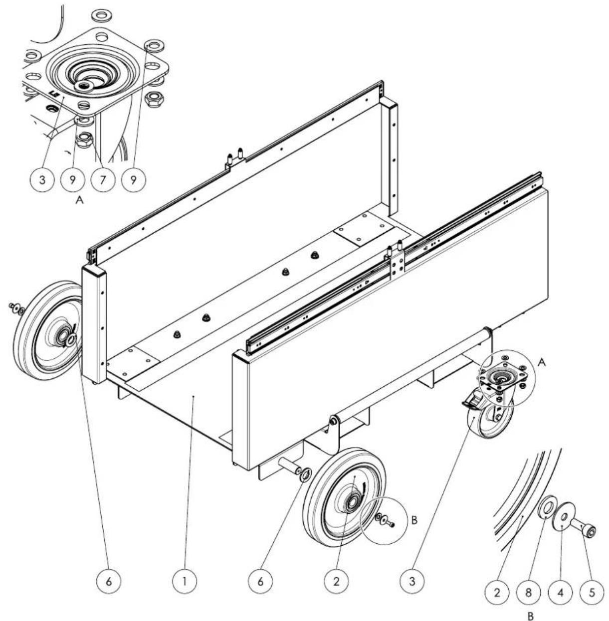
| No. Designation Article number | No. Designation Article number | |||
| 1 Bottom tray ZAT0001110 6 Washer P10001612 | ||||
| 2 Wheel P10001535 7 Nut P10000099 | ||||
| 3 Wheel P10001534 8 Washer P10000306 | ||||
| 4 Washer P10001119 9 Washer P10000016 | ||||
| 5 Screw P10001252 | ||||
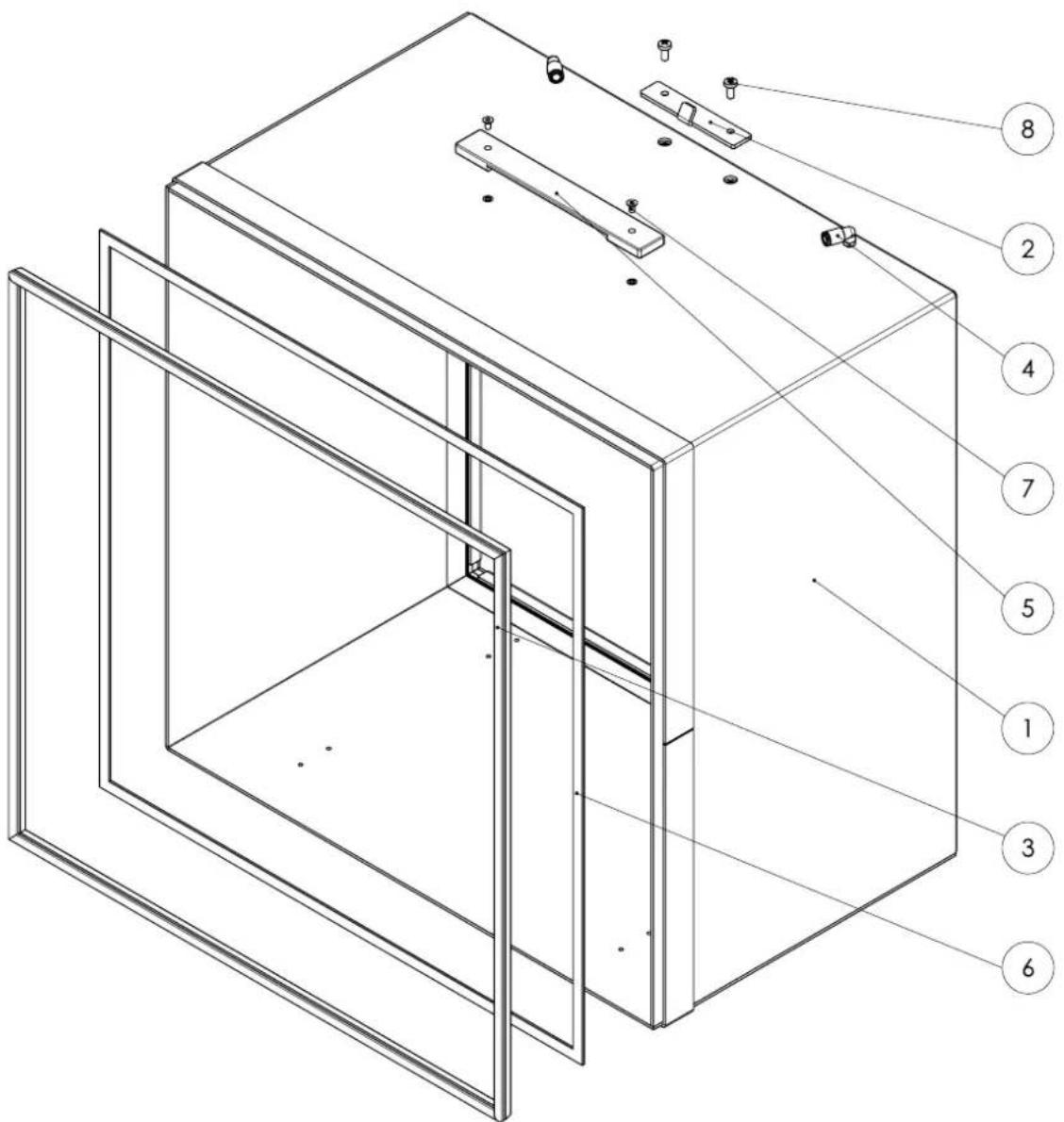
Prefilter Info

The position numbers of the spare parts differ from those describing the positions of the components mentioned in these instructions.

| No. Designation Article number | No. Designation Article number | ||
| 1 Prefilter housing P10003310 4 | Screw P10000849 | ||
| 2 Seal P10000290 5 Gasket strip | P10007992 | ||
| 3 Strap handle P10001543 |
HEPA Info

The position numbers of the spare parts differ from those describing the positions of the components mentioned in these instructions.
| No. Designation Article number | No. Designation Article number | ||
| 1 HEPA frame SBG P10003303 5 Strip handle P10001543 | |||
| 2 Hook plate P10003309 6 Gasket strip P10000357 | |||
| 3 Seal P10000290 7 Screw P10000849 | |||
| 4 Angle fitting P10001306 8 Screw P10001196 | |||
Fan Info

The position numbers of the spare parts differ from those describing the positions of the components mentioned in these instructions.
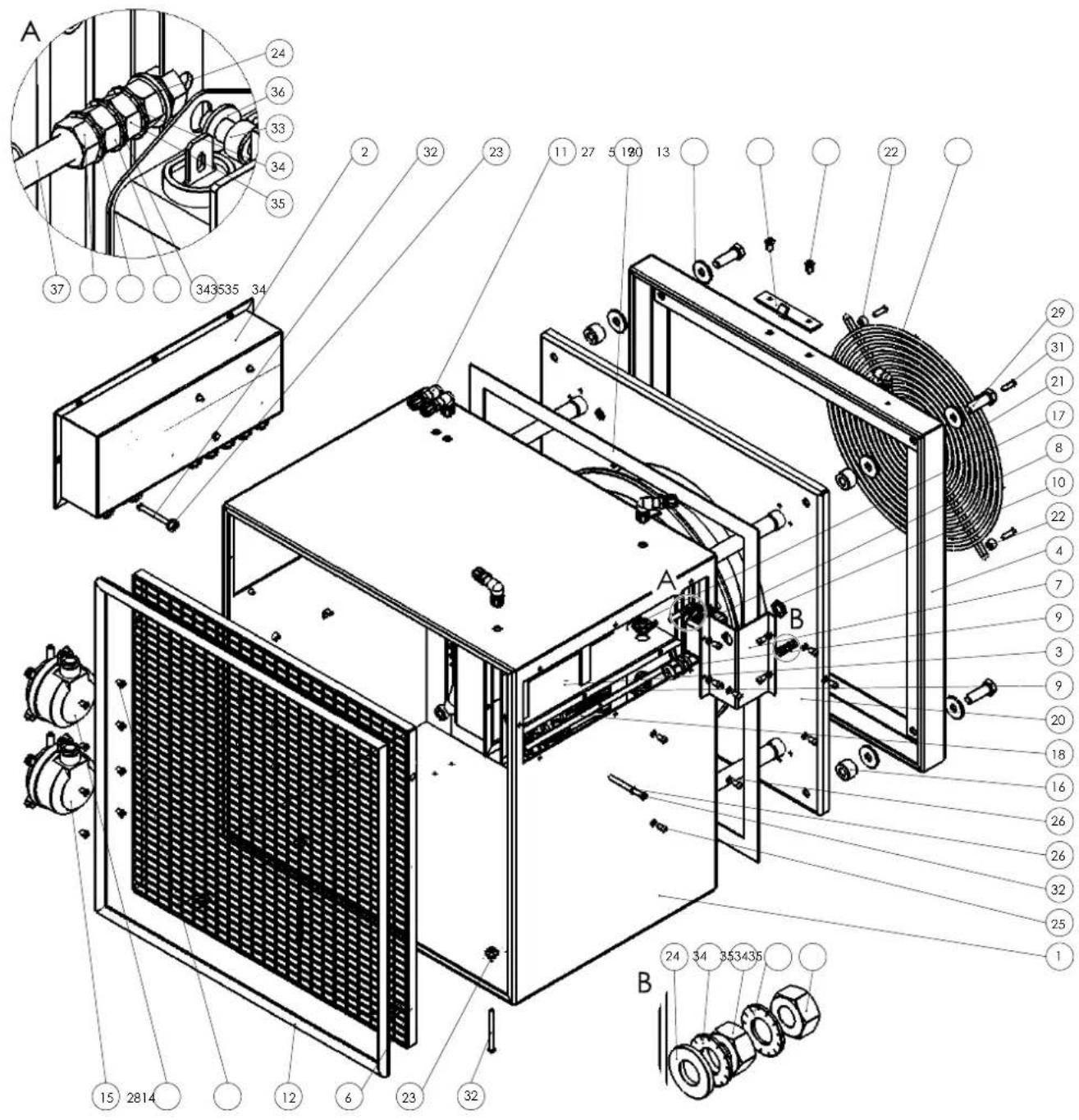
| No. Designation Article number | No. Designation Article number | |||
| 1 Fan housing P10003306 20 Fan | P10000595 | |||
| 2 Electric control box ZAT0001087 | 21 Protective grid P10006720 | |||
| 3 Cable box SBG P10008302 22 Spacer sleeve P10001110 | ||||
| 4 Fan frame P10003307 23 Feed-through P10001417 | ||||
| 5 Hook plate | P10003309 24 Washer | P10001134 | ||
| 6 Finger protection | P10008299 25 Screw | P10000782 | ||
| 7 Mains filter cover | P10008300 26 Washer | P10001310 | ||
| 8 Mains filter | P10001275 27 Washer | P10000490 | ||
| 9 Cable gland | P10007561 28 Screw | P10000322 | ||
| 10 Nut | P10003618 29 Screw | P10001461 | ||
| 11 Angle bulkhead fitting | P10001550 30 Screw | P10001196 | ||
| 12 Seal | P10001855 31 Screw | P10001640 | ||
| 13 Angle fitting | P10001306 32 Screw | P10008232 | ||
| 14 Differential pressure switch | P10001544 33 Screw | P10001129 | ||
| 15 Differential pressure switch | P10001545 34 Washer | P10000404 | ||
| 16 Spacer sleeve P10001434 35 Nut | P10000006 | |||
| 17 Nut | P10007562 36 Washer | P10000038 | ||
| 18 Gasket strip | P10000357 37 Screw | P10001958 | ||
| 19 Gasket strip | P10007992 | |||
Tension element Info

The position numbers of the spare parts differ from those describing the positions of the components mentioned in these instructions.
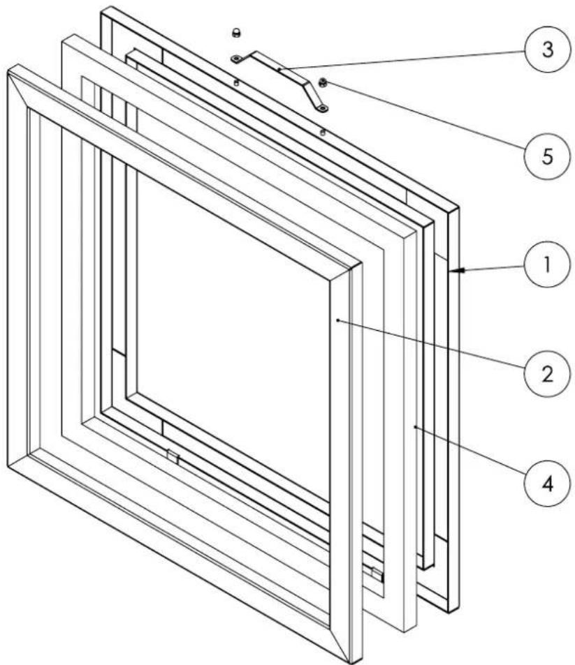
| No. Designation Article number | No. Designation Article number | ||
| 1 Tensioning frame P10003301 4 | Gasket strip P10001422 | ||
| 2 Tensioning frame P10003302 5 | Nut P10000768 | ||
| 3 Handle P10002158 |
Cover Info

The position numbers of the spare parts differ from those describing the positions of the components mentioned in these instructions.
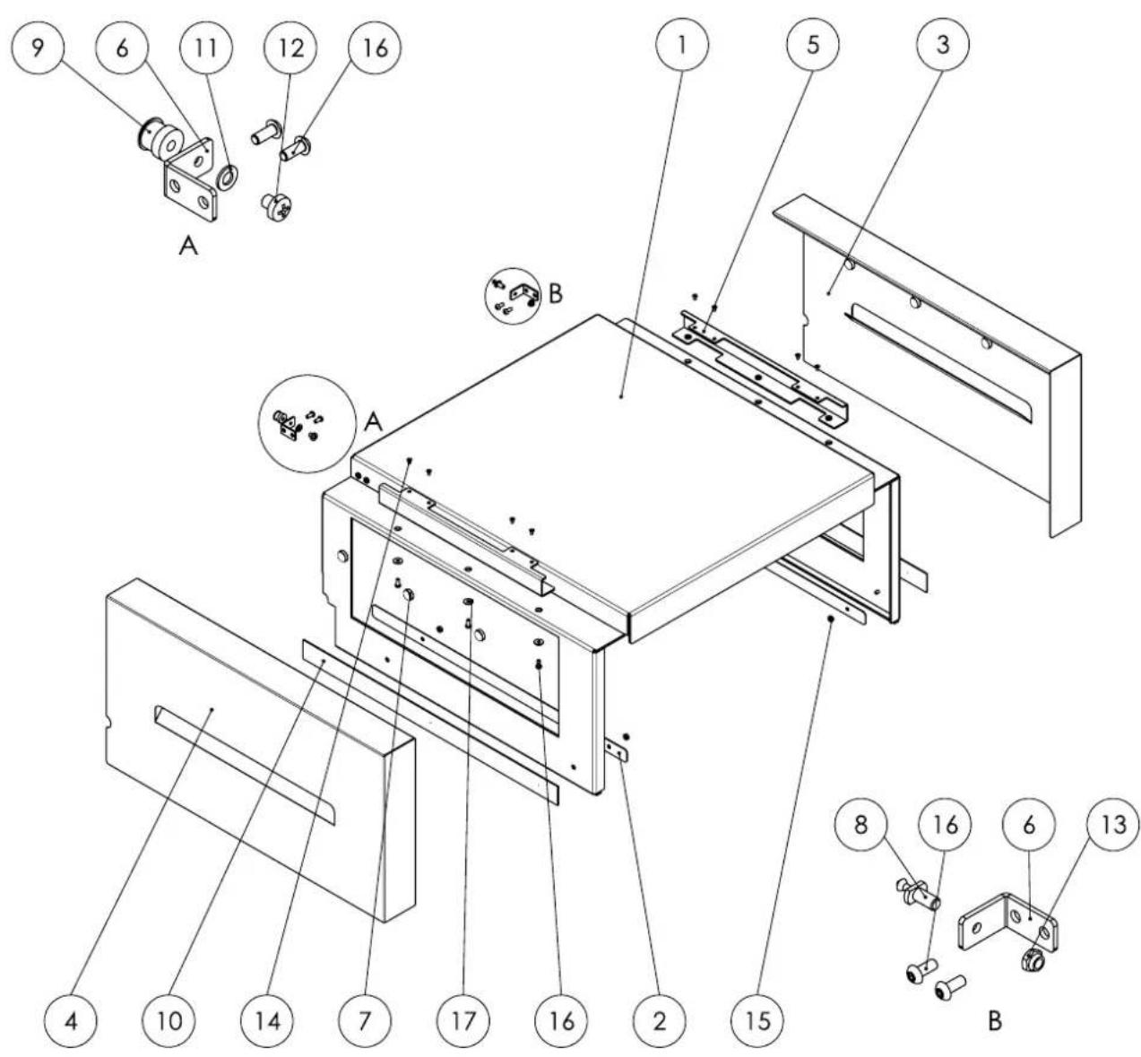
| No. Designation Article number | No. Designation Article number | |||
| 1 Cover SBG P10003312 10 Magnetic strip P10001741 | ||||
| 2 Reinforcement plate P10006757 | 11 Washer P10000211 | |||
| 3 Side panel P10003313 12 Screw | P10001179 | |||
| 4 Cover SBG P10003314 13 Nut P10000210 | ||||
| 5 Folding bracket P10003315 14 Screw | P10000783 | |||
| 6 Angle P10003316 15 Nut P10000208 | ||||
| 7 Magnet P10001547 16 Screw P10000782 | ||||
| 8 Closure plug P10001244 17 Washer P10000449 | ||||
| 9 Seal P10001243 | ||||
Electric control box Info

The position numbers of the spare parts differ from those describing the positions of the components mentioned in these instructions.
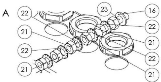
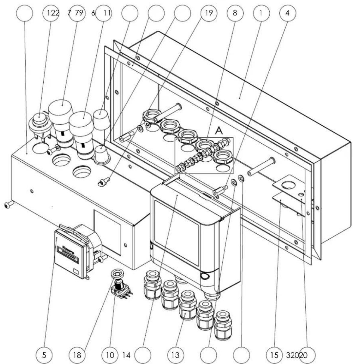
| No. | Designation Article number | No. Designation Article number | ||
| 1 | Electric control box P10006259 | 13 Cable gland P10007561 | ||
| 2 | Elec. mounting plate P10003305 | 14 Pressure sensor P10006258 | ||
| 3 | Gasket plate P10006260 15 Gas ket strip P10000357 | |||
| 4 | Spacer sleeve P10001555 16 Washer P10001134 | |||
| 5 | Operating hours counter P10001 | 137 17 Washer P10001310 | ||
| 6 | Gasket strip P10000357 18 Spacer sleeve P10000364 | |||
| 7 | Signal lamp P10002353 19 Screw | P10000782 | ||
| 8 | Nut | P10007562 20 Washer P10000038 | ||
| 9 | Cap | P10001249 21 Nut | P10000006 | |
| 10 | Potentiometer P10001751 22 Washer P10000404 | |||
| 11 | Rotary button | P10001250 23 Screw | P10001958 | |
| 12 | Switch | P10001376 | ||
Air outlet Info

The position numbers of the spare parts differ from those describing the positions of the components mentioned in these instructions.
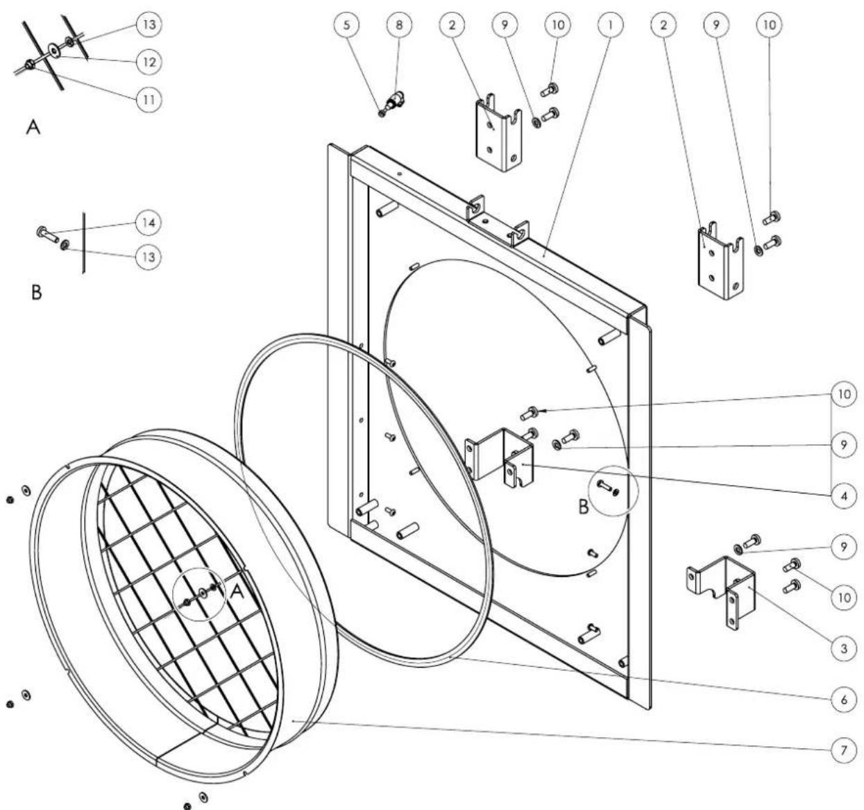
| No. Designation Article number | No. Designation Article number | ||
| 1 Air outlet P10003318 8 Angle fitting P10001306 | |||
| 2 Frame holder P10003319 9 Washer P10001133 | |||
| 3 Bumper bar holder P10003320 10 Screw P10001200 | |||
| 4 Bumper bar holder P10003321 11 Nut P10000013 | |||
| 5 Sealing plug P10001646 12 Washer P10000449 | |||
| 6 Gasket strip P10000357 13 Washer P10001310 | |||
| 7 Flanged collar P10000655 14 Screw P10001960 | |||
Frame Info

The position numbers of the spare parts differ from those describing the positions of the components mentioned in these instructions.
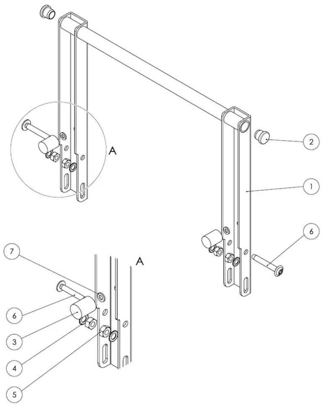
| No. Designation Article number | No. Designation Article number | ||
| 1 Frame P10003317 5 Nut P10001 | 188 | ||
| 2 Finned plug P10002041 6 Screw | P10001594 | ||
| 3 Rubber buffer P10001546 7 Washer | P10000019 | ||
| 4 Washer P10001111 |
Impact protection Info

The position numbers of the spare parts differ from those describing the positions of the components mentioned in these instructions.
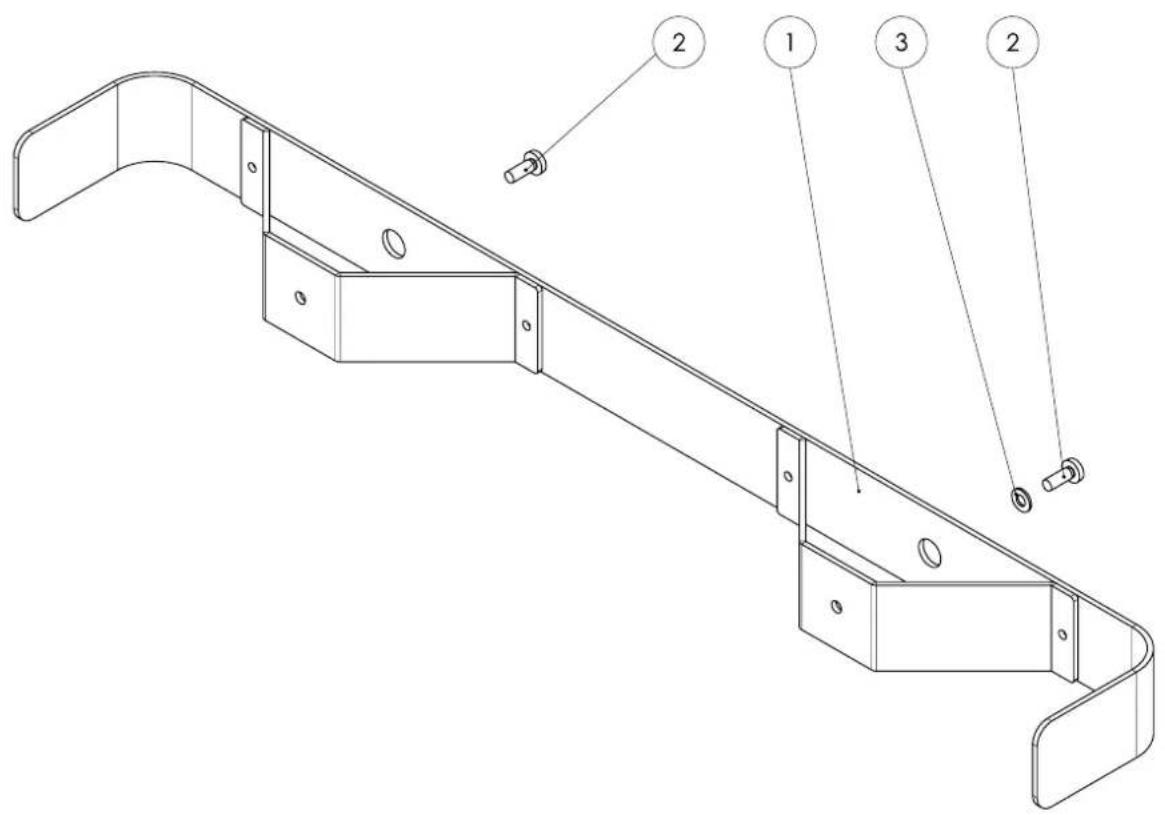
| No. Designation Article number | No. Designation Article number | ||
| 1 Bumper bar SBG P10003311 3 | Washer P10001133 | ||
| 2 Screw P10001200 |
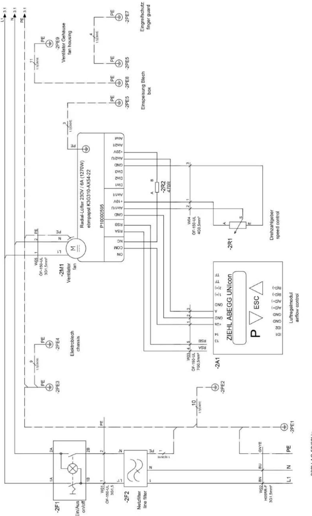
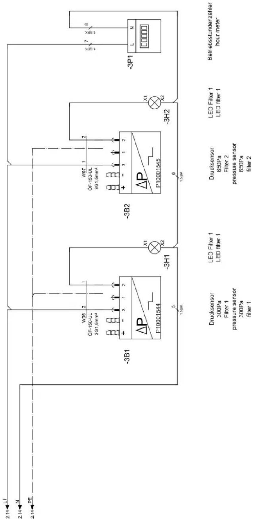
Circuit diagrams
EU Declaration of Conformity (original)
Declaration of conformity in accordance with the EC Machinery Directive 2006/42/EC, Annex II, Part 1, Section A
We - Trotec GmbH - declare in sole responsibility that the product designated below was developed, constructed and produced in compliance with all relevant provisions of the EC Machinery Directive in the version 2006/42/EC.
Product model / Product: TAC 5000
Product type: air cleaner
Year of manufacture as of: 2024
The product also complies with all relevant provisions of the following directives/regulations:
2011/65/EU
2014/30/EU
Applied harmonised standards:
EN ISO 12100:2010
EN ISO 13849-1:2015
EN ISO 13857:2019
EN ISO 14118:2018
EN 55011:2016
EN 55011:2016/A1:2017
EN 55011:2016/A11:2020
EN 60204-1:2018
EN 60335-1:2012
EN 60335-1:2012/AC:2014
EN 60335-1:2012/A11:2014
EN 60335-1:2012/A13:2017
EN 60335-1:2012/A15:2021
EN 60335-2-65:2003
EN 60335-2-65:2003/A11:2012
Applied national standards and technical specifications:
EN 55011:2016/A2:2012
EN 60335-1:2012/A16:2023
EN 60335-2-65:2003/A1:2008
EN 60335-2-65:2003/A12:2022
EN 60335-2-65:2003/A2:2022
EN 60335-2-65:2003/C1:2004
EN 62233:2008
Manufacturer and name of the authorised representative of the technical documentation:
Trotec GmbH
Place and date of issue:
Heinsberg, 17.11.2024
Joachim Ludwig, Managing Director
Trotec GmbH
Grebbener Str. 7
52525 Heinsberg
Germany
+492452962-0
+492452962-200
online@trotec.com
www.trotec.com
FR
TRADUCTION DE LA NOTICE ORIGINALE PURIFICATEUR D'AIR
Sommaire

TAC 5000
https://hub.trotec.com/?id=42770
Sécurité

TAC 5000
https://hub.trotec.com/?id=42770
Sikkerhed
https://hub.trotec.com/?id=42770
Turvallisuus
Allegato technique 13
https://hub.trotec.com/?id=42770
Sicurezza

TAC 5000
https://hub.trotec.com/?id=42770
Veiligheid
Telescooprails invetten

TAC 5000
https://hub.trotec.com/?id=42770

- SICHERHEIT
- INFORMATION ON THE USE OF THESE INSTRUCTIONS
- SYMBOLS
- DANGER
- WARNING
- WARNING OF ELECTRICAL VOLTAGE
- CAUTION
- NOTICE
- INFO
- FOLLOW THE MANUAL
- SAFETY
- INTENDED USE
- REASONABLY FORESEEABLE MISUSE
- PERSONNEL QUALIFICATION
- ELECTRICALLY SKILLED PERSON
- INSTRUCTED PERSON
- RESIDUAL RISKS
- BEHAVIOUR IN THE EVENT OF AN EMERGENCY
- INFORMATION ABOUT THE DEVICE
- DEVICE DESCRIPTION
- DEVICE DEPICTION
- TRANSPORT AND STORAGE
- TRANSPORT
- STORAGE
- ASSEMBLY AND START-UP
- SCOPE OF DELIVERY
- UNPACKING THE DEVICE
- ASSEMBLY
- SLIDING COVERS
- HINGED COVERS
- INSERTING THE FILTERS
- CONFIGURATION
- START-UP
- INSTALLATION OF THE DEVICE IN THE ROOM, THE AIR OF WHICH IS TO BE PURIFIED
- INSTALLATION OF THE DEVICE OUTSIDE OF THE ROOM, THE AIR OF WHICH IS TO BE PURIFIED
- CONNECTING THE POWER CABLE
- OPERATION
- OPERATING ELEMENTS
- SWITCHING THE DEVICE ON
- ADJUSTING THE AIR VOLUME
- SHUTDOWN
- AVAILABLE ACCESSORIES
- ERRORS AND FAULTS
- THE DEVICE DOES NOT START
- THE DEVICE IS LOUD OR VIBRATES
- THE DEVICE GETS VERY WARM, IS LOUD OR IS LOSING POWER
- THE DEVICE GIVES OFF AN UNPLEASANT ODOUR
- THE DEVICE STILL DOES NOT OPERATE CORRECTLY AFTER THESE CHECKS
- MAINTENANCE
- ACTIVITIES REQUIRED BEFORE STARTING MAINTENANCE
- CLEANING THE HOUSING
- VISUAL INSPECTION OF THE INSIDE OF THE DEVICE FOR DIRT
- FILTER CHANGE
- LUBRICATING THE TELESCOPIC SLIDES
- DISPOSAL
- ONLY FOR UNITED KINGDOM
- OVERVIEW INFO
- BASIC HOUSING INFO
- PREFILTER INFO
- HEPA INFO
- FAN INFO
- TENSION ELEMENT INFO
- COVER INFO
- ELECTRIC CONTROL BOX INFO
- AIR OUTLET INFO
- FRAME INFO
- IMPACT PROTECTION INFO
- EU DECLARATION OF CONFORMITY (ORIGINAL)
- THE PRODUCT ALSO COMPLIES WITH ALL RELEVANT PROVISIONS OF THE FOLLOWING DIRECTIVES/REGULATIONS
- APPLIED HARMONISED STANDARDS
- APPLIED NATIONAL STANDARDS AND TECHNICAL SPECIFICATIONS
- MANUFACTURER AND NAME OF THE AUTHORISED REPRESENTATIVE OF THE TECHNICAL DOCUMENTATION
- FR
- SOMMAIRE
- SÉCURITÉ
- SIKKERHED
- TURVALLISUUS
- SICUREZZA
- VEILIGHEID
- TELESCOOPRAILS INVETTEN
Brand : TROTEC
Model : TAC 5000
Category : Air purifier