PSG 85 B2 - Drill bit sharpener PARKSIDE - Free user manual and instructions
Find the device manual for free PSG 85 B2 PARKSIDE in PDF.

| Product type | Chainsaw chain sharpener |
| Model | PSG 85 B2 |
| Brand | Parkside |
| Rated input voltage | 230-240 V~, 50 Hz |
| Power consumption | 85 W (S2 15 min) |
| Idle speed | 5000 min⁻¹ |
| Adjustment angle | from -35° to +35° |
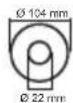
| Grinding wheel dimensions | Ø 104 x 3,2 x Ø 22 mm |
| Max. wheel speed | 40 m/s |
| Weight | 2,40 kg |
| Sound pressure level | 68,5 dB(A), K_pA = 3 dB |
| Protection class | I (with earth connection) |
| Protection type | IP X0 |
| Supplied material | Sharpener, handle, chain tensioning device, adjusting screw, workbench fasteners |
| Main functions | Sharpening of saw chains, angle adjustment, depth stop, anti-restart protection |
| Safety equipment | Transparent protective cover, On/Off switch, thermal protection |
| Maintenance and cleaning | Regular cleaning of ventilation slots, no chemicals, disconnect before maintenance |
| Spare parts | Grinding wheel (ref. 30211030), transparent cover, handle, etc., available at www.grizzly-service.eu |
| Warranty | 3 years (normal wear excluded) |
| Intended use | Sharpening of leisure chainsaw chains (not professional) |
| Operating temperature | Intermittent operation S2 15 min, then 5 min pause |
Frequently Asked Questions - PSG 85 B2 PARKSIDE
User questions about PSG 85 B2 PARKSIDE
0 question about this device. Answer the ones you know or ask your own.
Ask a new question about this device
Download the instructions for your Drill bit sharpener in PDF format for free! Find your manual PSG 85 B2 - PARKSIDE and take your electronic device back in hand. On this page are published all the documents necessary for the use of your device. PSG 85 B2 by PARKSIDE.
USER MANUAL PSG 85 B2 PARKSIDE
Translation of the original instructions
NL BE
Kettingslijpmachine
Before reading, unfold the page containing the illustrations and familiarise yourself with all functions of the device.
FR BE
GB/IE Translation of the original instructions Page
General description. 21
Scope of delivery. 21
Overview 21
Description of functions. 21
Technical data. 21
Safety information. 22
Symbols on the device 22
Symbols used in the instructions 23
General Safety Directions for Power
Tools 23
Additional safety instructions 25
Assembly. 27
Assembling the grinder 27
Setting up the device 27
Working with the device. 27
Switching on and off 28
Sharpening the saw chain. 28
Maintenance and cleaning 30
Cleaning. 30
Replacing the grinding disc. 30
Transport. 31
Storage. 31
Waste disposal/environmental
protection. 31
Replacement parts/Accessories..31
Guarantee 32
Repair Service. 33
Service-Center. 33
Importer 33
Translation of the original
EC declaration of conformity ....115
Exploded Drawing. 121
Introduction
Congratulations on the purchase of your new device. With it, you have chosen a high quality product.
During production, this equipment has been checked for quality and subjected to a final inspection. The functionality of your equipment is therefore guaranteed.

The operating instructions constitute part of this product. They contain important information on safety, use and disposal. Before using the product, familiarise yourself with all of the operating and safety instructions. Use the product only as described and for the applications specified.
Keep this manual safely and in the event that the product is passed on, hand over all documents to the third party.
Proper use
The chain sharpener is suitable for sharpening all common types of saw chain. The device is not intended for any other type of application (e.g. grinding with a coolant solution, grinding other workpieces or hazardous materials such as asbestos). The device is intended to be used by do-it-yourselfers. It was not designed for heavy commercial use. Commercial use will invalidate the guarantee.
The device is intended for use by adults. Children under the age of 16 may not use the device, except under supervision. The manufacturer is not liable for damage caused by improper use or incorrect operation.
General description
The illustration of the most important functional components can be found on the front and the back fold-out pages.
Scope of delivery
Unpack the device and check for completeness:
- Chain sharpener with pre-installed grinding discs
Handgrip - Chain tensioning unit with retaining screw
- Adjusting screw with fixing nut
- Two screws with nuts and washers for fixing to the table
Dispose of the packaging material properly.
Overview

1 On/off switch
Grinding head
Grinding disc cover 4 Handgrip
Mounting screws for grinding disc cover
Adjusting screw with adjusting nut for the depth stop
Chain guide rail
Grinding base
Adjusting nut for the chain tensioning unit
Scale for sharpening angle (+35^ to -35^)
Chain tensioning unit with rotary plate
Tension lever for fixing chain
Adjusting screw with adjusting nut for the chain feed
14 Stop
15 Cable holder (not depicted)
16 Mains connection cable
17 Grinding disc
17a Grinding disc nut (not visible)
18 Viewing guard
19 LED lamp (not depicted)
20 Ventilation holes (not depicted)

21Worktop
22 Stop notch
23 Screws
24 Nuts

25 Cutting tooth
Depth gauge nib
Description of functions
The device must be securely fixed to a worktop before the initial start-up. It is powered by an electric motor with thermal protection and restart stop for additional safety.
The sharpening angle can be easily adjusted from -35^ to +35^ . The chain guide rail has a variably adjustable stop. Sharpening is carried out by swivelling the grinding head. The device is provided with a viewing guard for the protection of the user. Please refer to the descriptions below for information on how the operating elements work.
Technical data
Chain Sharpener.........PSG 85 B2
Nominal input voltage. 230 - 240V 50Hz Power consumption ..85 W (S2 15 min)**
Rated resting time.. approx. 5 min
Protection class . II
Protection type . IP XO
Rated idle speed n_0 5000 min
Adjustment angle 35° left/right
Grinding disc dimensions Outer diameter .0104 mm Bore hole .022 mm Thickness .3,2 mm Disc speed max. 40m / s^ Weight 2,40 kg Sound pressure level (L_pA) ..68,5 dB (A); K_pA = 3 dB (A) Sound power level (L_wA) measured..74,1 dB(A); K_wA = 3 dB(A) Vibration (q_n) ..3,05 m/s2; K = 1,5m / s^2
The grinding disc must withstand a rotational speed of at least 40 m/s.
** A break is introduced after 15 minutes of uninterrupted operating duration until the device temperature differs 2K (2^) less than room temperature.
The specified noise emission value has been measured according to a standardised testing method and may be used for comparison with another power tool. The specified noise emission value may also be used for an introductory assessment of the exposure.

Warning: The noise emission value whilst actually using the power tool may vary from the given values regardless of the type and way in which the power tool is used. Try to keep the exposure to vibrations as low as possible. Examples of measures to reduce vibration exposure are the wearing of gloves when using the tool and limiting the working hours. All parts of the operating cycle have to be considered while doing so (for example, times when the power tool is switched off and times when it is switched on but running without any load).
Grinding disc PA 104 WA 100 (from scope of delivery):
lding speed n_0 max.7350 min1
Disc speed max. 40m / s^* Outer diameter 104 mm
Bore hole 22 mm
Thickness 3,2 mm

The supplied grinding disc is only suitable for sharpening hobby saw chains with a chain pitch of 1 / 4^ 0.325'' or 3 / 8''
Safety information

CAUTION! The following basic safety precautions must be observed while using power tools to protect against electric shock, injury and risk of fire. Please read all instructions before using this power tool and keep the safety instructions in a safe place.
Symbols on the device

Caution!

Injury hazard caused by rotating tool! Keep hands away.

Danger of electric shock! Remove the plug from the mains socket before carrying out maintenance and repair work.

Do not expose device to rain.

Please read and comply with the operating instructions for the device!

Risk of injury! Wear eye and hearing protection!

Wear respiratory protection.

Cutting hazard!
Wear cut-resistant work gloves.

Protection class II (Double insulation)

Electrical devices do not belong in domestic waste.

Caution! Do not stare into the bright light!
Grinding disc dimensions
Additional graphical symbols on the grinding disc

Never use faulty grinding discs
Symbols used in the instructions

Hazard symbol with information on the prevention of personal injury or property damage.

Hazard symbol (the hazard is explained instead of the exclamation mark) with information on damage prevention

Advisory symbol with information on how to best use the device

Wear protective gloves

Connect the device to the power supply.

Remove the mains plug
General Safety Directions for Power Tools

WARNING! Read all safety notices, instructions, illustrations and technical data that have been provided with this power tool. Omissions in the compliance with safety directions and instructions can cause electrical shock, fire and/or severe injuries.
Retain all safety directions and instructions for future use.
The term "power tool" in the warnings refers to your mains-operated (corded) power tool or battery-operated (cordless) power tool).
1) WORK AREA SAFETY
a) Keep work area clean and well lit. Cluttered or dark areas invite accidents.
b) Do not operate power tools in explosive atmospheres, such as in the presence of flammable liquids, gases or dust. Power tools create sparks which may ignite the dust or fumes.
c) Keep children and bystanders away while operating a power tool. Distractions can cause you to lose control.
2) ELECTRICAL SAFETY
a) Power tool plugs must match the outlet. Never modify the plug in any way. Do not use any adapter plugs with earthed (grounded) power tools. Unmodified plugs and matching outlets will reduce risk of electric shock.
b) Avoid body contact with earthed or grounded surfaces, such as pipes, radiators, ranges and refrigerators. There is an increased risk of electric shock if your body is earthed or grounded.
c) Do not expose power tools to rain or wet conditions. Water entering a power tool will increase the risk of electric shock.
d) Do not abuse the cord. Never use the cord for carrying, pulling or unplugging the power tool. Keep cord away from heat, oil, sharp edges or moving parts. Damaged or entangled cords increase the risk of electric shock.
e) When operating a power tool outdoors, use an extension cord suitable for outdoor use. Use of a cord suitable for outdoor use reduces the risk of electric shock.
f) If operating a power tool in a damp location is unavoidable, use a RCD (Residual Current Device) protected supply. Use of an RCD reduces the risk of electric shock.
3) PERSONAL SAFETY
a) Stay alert, watch what you are doing and use common sense when operating a power tool. Do not use a power tool while you are tired or under the influence of drugs, alcohol or medication. A moment of inattention white operating power tools may result in serious personal injury.
b) Use personal protective equipment. Always wear eye protection. Protective equipment such as dust mask, non-skid safety shoes, hard hat, or hearing protection used for appro
priate conditions will reduce personal injuries.
c) Prevent unintentional starting. Ensure the switch is in the off-position before connecting to power source and/or battery pack, picking up or carrying the tool. Carrying power tools with your finger on the switch or energising power tools that have the switch on invites accidents.
d) Remove any adjusting key or wrench before turning the power tool on. A wrench or a key left attached to a rotating part of the power tool may result in personal injury.
e) Do not overreach. Keep proper footing and balance at all times. This enables better control of the power tool in unexpected situations.
f) Dress properly. Do not wear loose clothing or jewellery. Keep your hair, clothing and gloves away from moving parts. Loose clothes, jewellery or long hair can be caught in moving parts.
g) If dust extraction and collection devices can be installed, make sure that these are connected and used correctly. Use of dust collection can reduce dust-related hazards.
h) Do not allow yourself to be lulled into a false sense of security and do not disregard the safety rules for power tools, even if you are familiar with the power tool after using it many times. Careless action can lead to serious injuries within a fraction of a second.
4) POWER TOOL USE AND CARE
a) Do not force the power tool. Use the correct power tool for your application. The correct power tool will do the job better and safer at the rate for which it was designed.
b) Do not use the power tool if the switch does not turn it on and off. Any power tool that cannot be controlled with the switch is dangerous and must be repaired.
c) Remove the plug from the wall socket and/or remove the rechargeable battery before you change the device's settings, change accessory parts or put away the power tool. Such preventive safety measures reduce the risk of starting the power tool accidentally.
d) Store idle power tools out of the reach of children and do not allow persons unfamiliar with the power tool or these instructions to operate the power tool. Power tools are dangerous in the hands of untrained users.
e) Look after the power tool and application tool carefully. Check for misalignment or binding of moving parts, breakage of parts and any other condition that may affect the power tool's operation. If damaged, have the power tool repaired before use. Many accidents are caused by poorly maintained power tools.
f) Keep cutting tools sharp and clean. Properly maintained cutting tools with sharp cutting edges are less likely to bind and are easier to control.
g) Use the power tool, accessories and tool bits etc. in accordance with these instructions, taking
into account the working conditions and the work to be performed. Use of the power tool for operations different from those intended could result in a hazardous situation.
h) Keep handles and grip surfaces dry, clean and free from oil and grease. Slippery handles and grip surfaces do not permit safe operation and control over the power tool in unexpected situations.
5) SERVICE
a) Have your power tool serviced by a qualified repair person using only identical replacement parts. This will ensure that the safety of the power tool is maintained.
Additional safety instructions
- Never use damaged attachment tools. Check attachment tools such as grinding discs for chipping or cracks before each use. If you have checked the attachment tool and attached it, keep yourself and any nearby persons out of the plane of the rotating attachment tool and allow the device to run for 1 min at the highest rotational speed. Damaged tools usually break during this test period.
The allowable rotation speed of the attachment tools must be at least as high as the highest rotation speed indicated on the power tool. Accessories that run faster than the allowable speed can break and fly apart.
- Ensure that you and all persons in the vicinity keep out of the
plane of the rotating disk. The protective guard is designed to protect the operator from flying debris and accidental contact with the abrasive surface.
- Grinders may only be used for the recommended attachment options. For example: Never grind using the side surfaces of the grinding discs. Grinding using the side surfaces can cause the grinding disc to burst and fly apart.
Always use undamaged clamping flanges of the correct size and shape for the grinding disc you selected. Suitable flanges support the grinding disc and thus reduce the danger of the grinding disc breaking.
-
The outside diameter and thickness of the attachment tool must correspond to the dimensions indicated for your power tool. Attachment tools which are wrongly dimensioned cannot be sufficiently shielded or controlled.
-
The grinding discs and flanges must fit the grinding spindle of your power tool precisely. Disks that do not fit the grinding spindle precisely rotate unevenly, vibrate sharply and can lead to loss of control.
-
Wear personal protective equipment. Depending on the application, use full face shields, eye protection or safety goggles. In so far as it is appropriate, wear dust masks, ear protection, gloves or special aprons which keep small grinding and material particles away from you.
Eye protection must be worn to protect against foreign matter flying around
during the various applications. Dust or breathing masks should filter the dust that is created during operation. If you are exposed to loud noise for a long time, you may suffer hearing loss.
-
Ensure that other people are at a safe distance to your working area. Anyone who enters the working area should wear personal protective equipment. Broken bits from the piece being worked or broken attachment tools can fly away and cause injuries even beyond the direct working area.
-
Keep the connection cable away from the rotating attachment tool. If you lose control of the device, the connection cable can become separated or caught and your hand or arm may be pulled into the rotating attachment tool.
-
Clean the ventilation slits of your power tool routinely. The motor air pulls dust into the housing and, should too much metallic dust collect, could cause electrical hazards.
-
Never use the power tool near flammable material. Never use the power tool when it is standing on a flammable surface such as wood. Sparks could ignite this material.
-
Do not use attachment tools which require liquid coolant. Using water or another coolant could lead to electrical shock.
-
Keep the mains cable and extension cable away from the grinding disc. In the event that it is damaged or severed, immediately disconnect the plug from the socket.
Do not touch the cable before it has been disconnected from the mains. Risk of electric shock.
- The replacement of the plug or the connection line must always be executed by the manufacturer of the electric tool or his/her customer service in order to avoid any hazards.
Assembly

Always fix the device with the supplied screws (M10x70).

Ensure that you have sufficient space in which to work, and that you do not endanger other people.

Always fasten the device on to the worktop with screws of sufficient length and thickness in order to maintain control of the device.

Assembling the grinder
1.. Screw the handgrip (4) onto the grinding head (2).
2. Loosen the retaining screw (9) on the chain tensioning unit (11).
3. Place the chain tensioning unit (11) on the grinding base (8) and tighten it with the retaining screw (9).
4. Secure the mains connection cable (16) in the cable holder (15).
Fixing adjusting screw:
- Screw the adjusting screw with the adjusting nut for the depth stop (A 6) through the threaded hole on the back of the device.

Setting up the device
- Thickness of table edge: 20 - 30 mm
-
Drill diameter: 10.5 mm
Screw gauge: M10 -
Use the stop notch (22) to position the device on the worktop (21). The grinding base (8) must project over the edge of the table.
- Mark the drill holes with a pen and remove the device.
- Drill two holes into the worktop (21).
- Screw the grinding base to the worktop using the screws (23) and nuts (24) supplied.
Working with the device

Caution!
Only use grinding discs and accessories recommended by the manufacturer. Using other attachment tools and other accessories may represent a risk of injury to you. Never operate the device without a viewing guard. Do not use any saw blades. Always remove the mains plug before working on the device.
Always inspect the grinding disc before starting the device: Check the distance between the viewing guard and the grinding disc. Do not use any broken, cracked or otherwise damaged grinding discs. Only switch the device on once it is safely fixed to the worktop. Never operate the device without a viewing guard, chain tensioning unit or grinding disc cover. Risk of injury!

Make sure that you have a secure footing when working and always ensure that the device is securely fastened to the worktop.
GB E
Only use grinding discs sold in specialist shops, the dimensions of which do not deviate from the dimensions given in the technical data (Ø104x3.2xØ22 mm). Information on reordering grinding discs can be found under "Spare parts/accessories".
Caution! Risk of injury! Wear eye and hearing protection!
When working with the saw chain, wear cut-resistant protective gloves and, if necessary, an apron to prevent cuts.
Keep your hands away from the grinding disc and teeth of the chain when the device is in operation. Do not move the chain by hand. There is a risk of injury.
Switching on and off
Only switch the device on once it is safely fixed to the worktop.
Make sure that the power supply voltage matches the voltage rating indicated on the device's type plate.
Connect the device to the power supply.
- Press the ON/OFF switch (position "I") to start the device. The device starts up (see A 1).
- Press the ON/OFF switch (position "0") to switch off the device. The device switches off (see A 1).
The grinding disc still runs even after the device has
been switched off. There is a risk of injury.
Thermal protection with restart stop:
If the device automatically shuts down due to overuse, it will not restart automatically. Press the ON/OFF switch (position "I") again to start the device. The device starts up (see A 1).
Trial run:
Always carry out a trial run of at least 30 seconds duration without load before carrying out your first grinding procedure and after every grinding disc replacement. Switch the device off immediately if the disc is not rotating smoothly, if considerable vibration occurs or if you hear abnormal noises.
D Sharpening the saw chain
When working under dust-prone conditions, ensure ventilation holes are clear (see "Maintenance and cleaning").
An incorrectly sharpened saw chain can cause damage and increases the danger of saw kickback! Ensure the chain is precisely aligned. Observe the correct sharpening angle and saw chain minimum dimensions. Remove as little material as possible.
Do not grind into links (a) or connecting links (b),
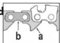
otherwise the saw chain may break.
If this is not observed, there is a risk of accidents when working with the chainsaw.

Information on sharpening
ean the saw chain before sharpening. Remove oily wood or oil residues with a brush or cloth.
After sharpening, all the cutting links must have the same length and breadth.
The chain has become worn down and must be replaced with a new saw chain when only around 4mm of the cutting tooth remains.
Inserting the saw chain:
- To open the chain guide rail, turn the tension lever (12) counterclockwise. To do this, return the tension lever to its initial position several times. To release the tension lever, pull the tension lever outwards and, after returning it to its original position, allow it to re-engage.
- Place the saw chain into the chain guide rails (7). The cutting edges must face the grinding discs (17).
- Fold the stop (14) down and pull back the saw chain until the cutting tooth (25) to be sharpened rests on the stop (see figure ①).
Adjusting the working angle:
- Unscrew the retaining screw (B 9) and use the scale (10) to adjust the required sharpening angle on the rotary plate
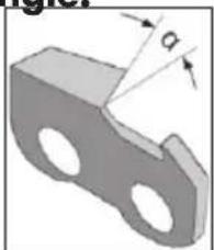
of the chain tensioning unit (11). Follow the instructions of the saw chain manufacturer regarding the required sharpening angle .
- Retighten the retaining screw.
Adjusting the stop:
- Move the grinding head (2) on the handgrip (4) downwards with the motor switched off.
- Using the adjusting screw for the chain feed (13a), bring the cutting tooth (25) closer to the grinding disc (17) until the cutting tooth is in contact with the grinding disc (see figure ②). Secure the adjusting screw (13a) using the adjusting nut (13b).
- Fix the chain links in the chain guide rail (7) by turning the tension lever (12) clockwise (see 1.).
- Adjust the depth stop using the adjusting screw (6a) so that the grinding disc (17) touches the base of the tooth (see figure ②). Secure the grinding depth with the adjusting nut (6b).
Sharpening:
- Turn the device on (see "Switching on/off").
- Press the handgrip (4) gently to move the grinding head (2) downwards and sharpen the cutting tooth (25). The grinding disc (17) must not be brought to a standstill with the brakes. To avoid this, reduce the pressure in good time.
- Switch off the device to move the saw chain onward. Loosen the tension lever (12) and fix the next chain link to be sharpened using the adjusted stop (14) and the tension lever in the chain guide rail (7)

First sharpen the teeth on one side of the chain. Then adjust the sharpening angle and sharpen the teeth on the other side.
Test depth gauge distance (see D fig ③)
The cutting parts of the chain are the cutting links which consist of a cutting tooth (25) and a depth gauge nib (26). The vertical distance between these two determines the depth gauge distance A.
- After every third sharpening, check the depth gauge distance A according to the saw chain manufacturer's instructions.
- File the tip of the depth gauge nib (26) with a flat file and round off the depth gauge nib slightly after resetting. The original shape must be maintained.
Maintenance and cleaning

Remove the mains plug before carrying out any adjustments, maintenance or repair work.

Have any work on the device that is not described in this instruction guide performed by a professional. Only use original parts. Allow the device to cool off before performing any maintenance or cleaning. There is a danger of burns!
Always check the device before using it for obvious defects such as loose, worn or damaged parts, correct the positioning of screws or other parts. Examine the grind
ing disc in particular (A 17). Exchange the damaged parts.
Cleaning

Do not use any cleaning agents or solvents. Chemical substances may attack the plastic parts of the device. Never clean the device under running water.
Thoroughly clean the device after every use.
Clean the ventilation openings ( A 20) and the surface of the device with a soft brush, a paint brush or cloth.

Replacing the grinding disc

Information on replacement:
- Never operate the device without a viewing guard (A 18).
- Ensure that the rotation speed stated on the grinding disc (A 17) is the same or higher than the nominal rotation speed of the device. Ensure that the disc dimensions match those of the device.
- Only use grinding discs in perfect working order (sound test).
- Only use grinding discs with a locating hole of 22 mm . Never re-drill a locating hole which is too small for the grinding disc to make it larger.
- Never use separate bushings or adapters in order to make grinding discs with a hole that is too large fit the device.
- Do not use any saw blades.
Always reassemble the device completely after replacing the grinding disc.

Switch off the device and unplug the mains plug.
Allow the device to cool down.

Use protective gloves when working with grinding discs.
- Unscrew the 3 mounting screws to the grinding disc cover (5).
- Remove the grinding disc cover (3).
- Unscrew the grinding disc nuts (17a) by hand.
- Remove the grinding disc from the holder (17).
- Place the new grinding disc onto the holder and manually screw on the grinding disc nut.
- Screw the grinding disc cover (3) back on.

The grinding disc nut must not be screwed too tightly in order to avoid a breaking of the grinding disc and nut
- Trial run: Always carry out a trial run of at least 30 seconds duration without load before carrying out your first grinding procedure and after every grinding disc replacement. Switch the device off immediately if the disc is not rotating smoothly, if considerable vibration occurs or if you hear abnormal noises.
Transport
Always transport the device with one hand on the grinding head (2) and the other hand on the grinding base (8).
- Never carry the device by its connection cable.
Storage
- Store the device in a dry and dustproof location and out of reach of children.

Grinding discs must be dry and stored upright and should never be stacked.
Waste disposal/environmental protection
Return the tool, accessories and packaging to a recycling centre when you have finished with them.

Electrical devices do not belong in domestic waste.
- Hand over the device at an utilization location. The plastic and metal parts employed can be separated out and thus recycled use can be implemented. Ask our Service-Center for details.
Defective units returned to us will be disposed of for free.
Replacement parts/ Accessories
Spare parts and accessories can be obtained at www.grizzly-service.eu
If you have issues ordering, please use the contact form.
If you have any other questions, contact the "Service-Center" (see page 33).
Position Description Order no.
| A17 Grinding disc (Ø104x3,2xØ22 mm) 30211030 | |
| A17a Grinding disc nut | 91102831 |
| A4 Handgrip | 91102833 |
| A18 Viewing guard | 91102839 |
| A11 Chain tensioning unit with rotary plate | 91102830 |
Guarantee
Dear Customer, This equipment is provided with a 3-year guarantee from the date of purchase. In case of defects, you have statutory rights against the seller of the product. These statutory rights are not restricted by our guarantee presented below.
Terms of Guarantee
The term of the guarantee begins on the date of purchase. Please retain the original receipt. This document is required as proof of purchase.
If a material or manufacturing defect occurs within three years of the date of purchase of this product, we will repair or replace - at our choice - the product for you free of charge. This guarantee requires the defective equipment and proof of purchase to be presented within the three-year period with a brief written description of what constitutes the defect and when it occurred.
If the defect is covered by our guarantee, you will receive either the repaired product or a new product. No new guarantee period begins on repair or replacement of the product.
Guarantee Period and Statutory Claims for Defects
The guarantee period is not extended by the guarantee service. This also applies for
replaced or repaired parts. Any damages and defects already present at the time of purchase must be reported immediately after unpacking. Repairs arising after expiry of the guarantee period are chargeable.
Guarantee Cover
The equipment has been carefully produced in accordance with strict quality guidelines and conscientiously checked prior to delivery.
The guarantee applies for all material and manufacturing defects. This guarantee does not extend to cover product parts that are subject to normal wear and may therefore be considered as wearing parts (e.g. Grinding disc) or to cover damage to breakable parts (e.g. Switches, Viewing guard).
This guarantee shall be invalid if the product has been damaged, used incorrectly or not maintained. Precise adherence to all of the instructions specified in the operating manual is required for proper use of the product. Intended uses and actions against which the operating manual advises or warns must be categorically avoided.
The product is designed only for private and not commercial use. The guarantee will be invalidated in case of misuse or improper handling, use of force, or interventions not undertaken by our authorised service branch.
Processing in Case of Guarantee
To ensure quick handling of you issue, please follow the following directions:
Please have the receipt and item number (IAN 340614_1910) ready as proof of purchase for all enquiries.
- Please find the item number on the rating plate.
- Should functional errors or other defects occur, please initially contact the service department specified below by telephone or by e-mail. You will then receive further information on the processing of your complaint.
- After consultation with our customer service, a product recorded as defective can be sent postage paid to the service address communicated to you, with the proof of purchase (receipt) and specification of what constitutes the defect and when it occurred. In order to avoid acceptance problems and additional costs, please be sure to use only the address communicated to you. Ensure that the consignment is not sent carriage forward or by bulky goods, express or other special freight. Please send the equipment inc. all accessories supplied at the time of purchase and ensure adequate, safe transport packaging.
Repair Service
For a charge, repairs not covered by the guarantee can be carried out by our service branch, which will be happy to issue a cost estimate for you.
We can handle only equipment that has been sent with adequate packaging and postage.
Attention: Please send your equipment to our service branch in clean condition and with an indication of the defect.
Equipment sent carriage forward or by bulky goods, express or other special freight will not be accepted.
We will dispose of your defective devices free of charge when you send them to us.
Service-Center
GB Service Great Britain
Tel.: 0800 404 7657
E-Mail: grizzlyl@lidl.co.uk
IAN 340614 1910
IF Service Ireland
Tel.: 1890 930 034
(0,08 EUR/Min., (peak))
(0,06 EUR/Min., (off peak))
E-Mail: grizzlyy@lidl.ie
IAN 340614_1910
Importer
Please note that the following address is not a service address. Please initially contact the service centre specified above.
Garantie - France. 48
| GB IE | Translation of the original EC declaration of conformity |
| We hereby confirm that the Chain Sharpener PSG 85 B2 series Serial number 202002000001 - 202002156975 conforms with the following applicable relevant version of the EU guidelines: | |
| 2006/42/EC • 2014/30/EU • 2011/65/EU* | |
| In order to guarantee consistency, the following harmonised standards as well as national standards and stipulations have been applied: | |
| EN 62841-1:2015 • EN 62841-3-4:2016+A11:2017 EN 62841-3-10:2015/A11:2017 • EN 55014-1:2017 • EN 55014-2:2015 EN 62321-3-1:2014 • EN 61000-3-2:2014 • EN 61000-3-3:2013 | |
| This declaration of conformity is issued under the sole responsibility of the manufacturer: | |
| CE Grizzly Tools GmbH & Co. KG Stockstädter Straße 20 63762 Großbostheim Germany 03.04.2020 | Christian Frank Documentation Representative |
- The object of the declaration described above satisfies the provisions of Directive 2011/65/EU of the European Parliament and the Council of 8 June 2011 on limiting the use of certain harmful substances in electrical and electronic appliances.