
PSS 2 A1 - Tab box PARKSIDE - Free user manual and instructions
Find the device manual for free PSS 2 A1 PARKSIDE in PDF.

| Product type | Miter box with bevel square |
| Brand | Parkside |
| Model | PSS 2 A1 |
| Use | Angle measurement (85° to 180°) and miter cutting |
| Max workpiece height | 100 mm |
| Workpiece width | 5 to 30 mm |
| Angle measurement range | 85° - 180° (interior/exterior) |
| Included items | Bevel square, 2 movable arms, 2 clamping brackets, 2 retaining jaws, 2 guide bars, 4 clips, 4 screws, 4 nuts, 1 Allen key 4 mm |
| Safety | Wear safety goggles, gloves, ear protection and dust mask |
| Cleaning | Use a soft brush and a dry cloth; do not use aggressive products |
| Storage | Clean, dry place away from sunlight |
| Customer service (France) | 0800 919270 / kompernass@lidl.fr |
| Warranty | Void if used improperly, abusively or modified without authorization |
| Assembly required | Yes, attach guide bars with provided screws and nuts |
| Dimensions (approx.) | Approx. 30 x 20 x 10 cm |
| Weight (approx.) | Approx. 0.8 kg |
Frequently Asked Questions - PSS 2 A1 PARKSIDE
User questions about PSS 2 A1 PARKSIDE
0 question about this device. Answer the ones you know or ask your own.
Ask a new question about this device
Download the instructions for your Tab box in PDF format for free! Find your manual PSS 2 A1 - PARKSIDE and take your electronic device back in hand. On this page are published all the documents necessary for the use of your device. PSS 2 A1 by PARKSIDE.
USER MANUAL PSS 2 A1 PARKSIDE
natural_image
Close-up of a mechanical device with a cylindrical component and metallic shaft on a wooden floor (no visible text or symbols)Operating instructions
FR BE
GB/IE Operating instructions Page 1
Contents
Introduction 2
Information about these operating instructions ..... 2
Proper use 2
Safety 3
Contents of package/parts description ..... 4
Installation 5
Use 6
Measuring angles 6
Clamping and sawing a wooden workpiece .... 7
Cleaning and storage 8
Disposal 9
Service 10
Importer 10
Introduction
Information about these operating instructions

Congratulations!
You have purchased a high-quality product. Familiarise yourself with the product before using it for the first time. To do this, read the following operating instructions thoroughly. Use the product only as described and for the range of applications specified. Keep these operating instructions in a safe place. Please also pass these operating instructions on to any future owner(s).
Proper use
The product is used exclusively for measuring angles and then sawing exact mitres. Internal and external angles from 85^ to 180^ can be measured. You can saw wooden workpieces, e.g. skirting boards, with a max. height of 100 mm and a width of 5 to 30 mm. Commercial or industrial use is not permitted. No liability will be assumed in cases of improper use. No liability will be assumed for damage caused by misuse or improper handling, the use of force or unauthorised modification. The risk is borne solely by the user.
Safety
- Check the product before every use to make sure it is in perfect condition. Do not use the product if it is damaged in any way.
■ Do not allow children to use the product unless they are being supervised. Children are not always able to correctly recognise potential dangers. This product is not a toy.
This product is not intended for use by individuals (including children) with reduced physical, sensory, or mental capabilities. It may also not be used by individuals who lack experience and/or knowledge unless they are supervised by a person responsible for their safety or have received instructions on how to use the product from such a person.
■ Some of the supplied parts can be swallowed. If a part is swallowed, seek medical advice immediately.
Use protective equipment. For your own safety, always wear ear muffs, a breathing mask/dust mask, safety goggles and safety gloves.
■ All parts must be properly fitted before use otherwise there is a risk of serious injury!
■ Firmly clamp the wooden workpiece you are working on.
■ Rusty discolorations or other signs of chemical or mechanical change to the parts can cause premature failure of the parts.
Contents of package/parts description
- Bevel & Mitre Box
-Movable arms 1
-Tensioning clamps ②
-Retaining jaws ③
-Release buttons 4
-Locking buttons 5
-Lock nut 6
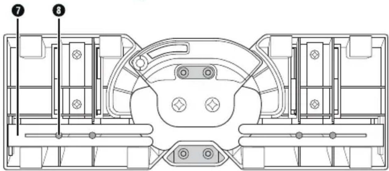
- 2 × guide rods ⑦
- 4 × retaining clips ⑧
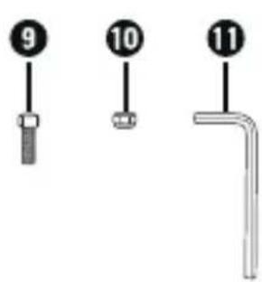
- 4 × screws ⑨
- 4 × retaining nuts 10
- Hex key SW 4 mm ⑪
● These operating instructions
NOTE
▶ Check the package for completeness and signs of visible damage.
If the delivery is incomplete or damage has occurred as a result of defective packaging or during transport, contact the customer service hotline (see section Service).
Installation
Remove the retaining clips ⑧ from the underside of the product and remove the guide rods ⑦ (see fig. 1).
◆ Re-attach the retaining clips ⑧ in case you want to store the guide rods ⑦ on the underside of the product at a later time.
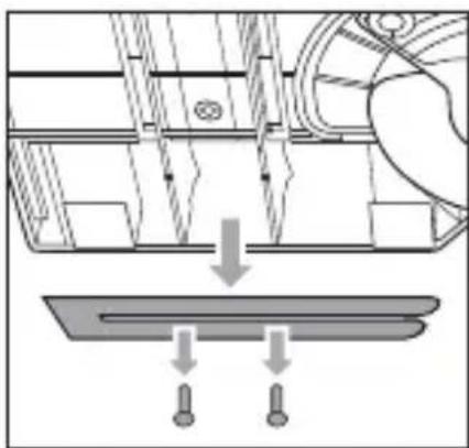
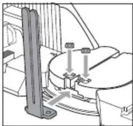
♦ Push the first guide rod ⑦ into one of the fittings and place only one retaining nut ⑩ with the flat side first into the recess (see fig. 2).
- Hold the retaining nut 10 in place with one finger and turn the product over.
♦ Screw one of the screws ⑨ tightly into the retaining nut ⑩ using the hex key ⑪ (see fig. 3).
◆ Repeat the process to fix both guide rods ⑦ using all of the retaining nuts ⑩ and screws ⑨.
natural_image
Technical diagram showing a mechanical assembly with a downward arrow and two bolted components below (no text or symbols)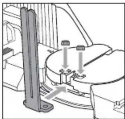
natural_image
Technical line drawing of a mechanical assembly with no visible text or symbols
natural_image
Technical line drawing of a mechanical component with no visible text or symbols▶ Internal and external angles from 85^ to 180^ can be measured.
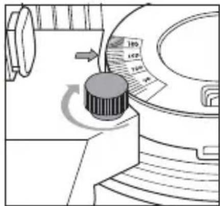
- Undo the retaining nut ⑥ one turn only so that the screw cannot fall out.
Place the product in or around a corner to measure an inside or outside angle. The movable arms ① must lie flat against the wall (see fig. 4).
- Tighten the retaining nut ⑥. The arrows on the movable arms ① point to the scale where you can read off the measured angle (see fig. 5).
natural_image
Technical line drawing of a mechanical assembly with no visible text or symbols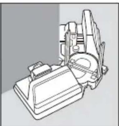
natural_image
Technical line drawing of a mechanical assembly (no text or symbols visible)
natural_image
Diagram of a mechanical device with a rotary knob and scroll wheel (no text or symbols)Fig. 4 Fig. 5
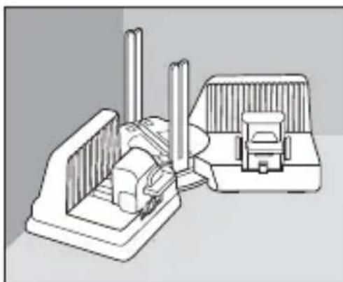
Clamping and sawing a wooden workpiece
NOTE
▶ You can saw wooden workpieces, e.g. skirting boards, with a max. height of 100 mm and a width of 5 to 30 mm.
Hold down the release buttons ④ and push the tensioning clamp ② onto the wooden workpiece to position it.
Place the wooden workpiece between the retaining jaw ③ and the tensioning clamp ②. Make sure that the wooden workpiece is guided past the guide rods ⑦ (see fig. 6).
Hold down the release buttons ④ and push the tensioning clamp ② onto the wooden workpiece. Let go of the release buttons ④ once the wooden workpiece is clamped (see fig. 6).
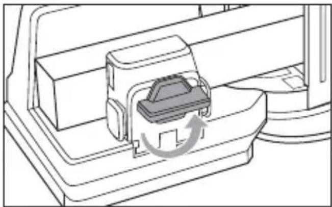
Turn the locking button ⑤ clockwise to fix the wooden workpiece in place (see fig. 6).
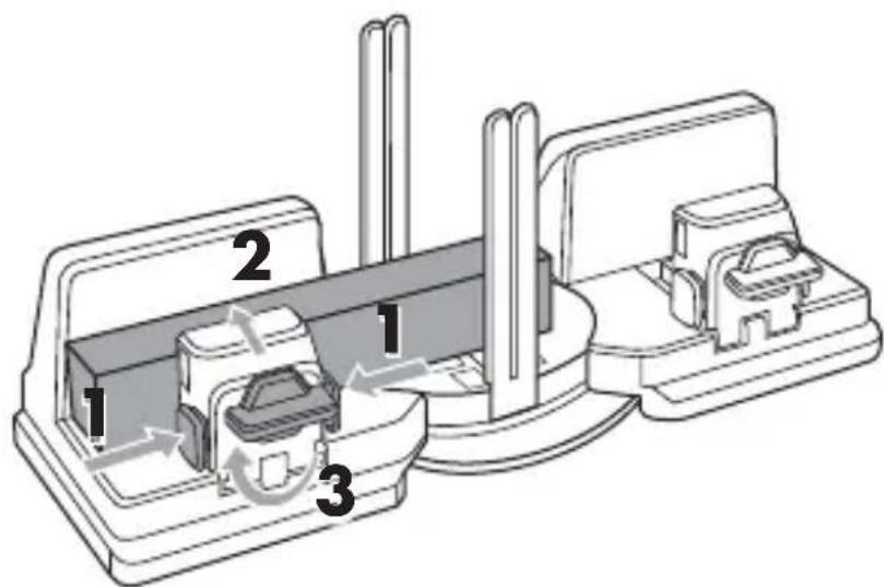
Fig.
6
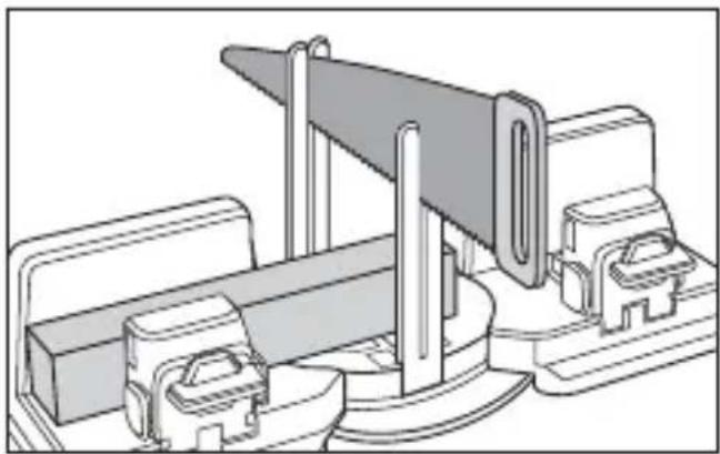
- Hold the product firmly with one hand on one of the movable arms ①.
Using the other hand, guide the saw through the guide rods from above (see fig. 7).
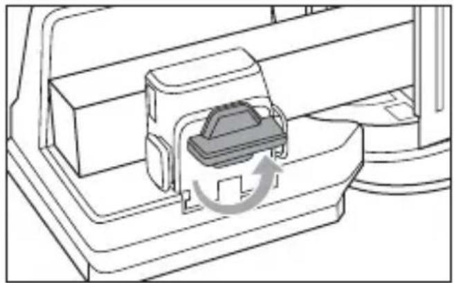
◆ Saw through the wooden workpiece. - Turn the locking button ⑤ anticlockwise to release the wooden workpiece (see fig. 8).
◆ Remove the wooden workpiece.
natural_image
Technical line drawing of a mechanical assembly with no visible text or symbols
natural_image
Diagram of a mechanical device with a component inserted, showing a circular arrow indicating rotation (no text or symbols present)Fig. 7 Fig. 8
Cleaning and storage
ATTENTION! PROPERTY DAMAGE!
▶ Do not use aggressive or abrasive cleaning agents, as these can damage the surfaces of the product.
Use a soft dry brush to remove the sawdust from the product.
You can also clean the product using a dry cloth.
◆ Store the product in a clean, dry location away from direct sunlight.
If required, dismantle the guide rods ⑦ and attach them to the underside of the product using the retaining clips ⑧.
Disposal

Dispose of the product via an approved waste disposal company or your municipal waste disposal facility.
Comply with all applicable regulations. Please contact your waste disposal facility if you are in any doubt.

Your local community or municipal authorities can provide information on how to dispose of the worn-out product.

The product is recyclable, subject to extended producer responsibility and is collected separately.
Dispose of the packaging in an environmentally friendly manner.
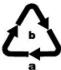
Note the labelling on the packaging and separate the packaging material components for disposal, if necessary. The packaging materials are labelled with abbreviations (a) and numbers (b) with the following meanings: 1–7: plastics, 20–22: paper and cardboard, 80–98: composites.
Service

Service Great Britain
Tel.: 0800 404 7657
E-Mail: kompernass@lidl.co.uk

ServiceIreland
Tel.: 1890 930 034
(0,08 EUR / Min., (peak))
(0,06 EUR / Min., (off peak))
E-Mail: kompernass@lidl.ie
IAN 364230_2010
Importer
Please note that the following address is not the service address. Please use the service address provided in the operating instructions.
KOMPERNASS HANDELS GMBH
BURGSTRASSE 21
44867 BOCHUM
GERMANY
www.kompernass.com
Inhaltsverzeichnis
Einführung 12
natural_image
Technical diagram showing a mechanical assembly with arrows indicating process flow (no text or symbols present)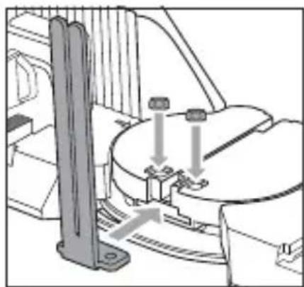
natural_image
Technical line drawing of a mechanical assembly with no visible text or symbols
natural_image
Technical diagram of a mechanical component with a screw and mounting bracket (no text or symbols)natural_image
Three-panel technical illustration showing mechanical components and a close-up of a device with a knob (no text or symbols)Abb. 4 Abb. 5
Abb.
6
natural_image
Technical line drawing of a mechanical assembly with no visible text or symbolsAbb. 7 Abb. 8
natural_image
Diagram of a vehicle interior showing a car trunk and dashboard with a gear shift indicator (no text or symbols)KOMPERNASS HANDELS GMBH
BURGSTRASSE 21
44867 BOCHUM
DEUTSCHLAND
www.kompernass.com
Table des matières
Introduction 22
natural_image
Mechanical assembly diagram showing a component being lowered into a flat plate with two bolt holes (no text or labels)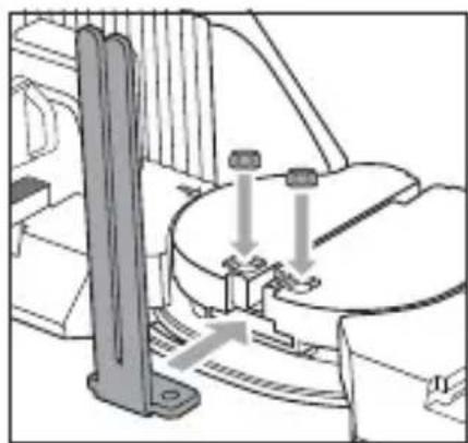
natural_image
Mechanical assembly diagram showing a rotating component with mounting brackets and a vertical rod (no text or symbols)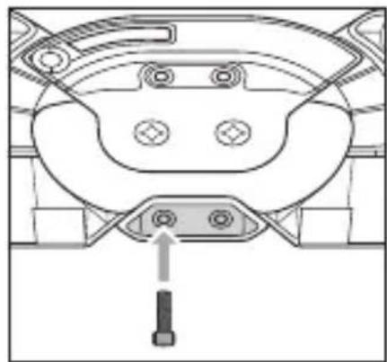
natural_image
Technical diagram of a mechanical component with mounting holes and a screwdriver (no text or symbols)natural_image
Technical line drawing of a mechanical assembly with no visible text or symbols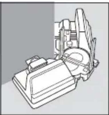
natural_image
Technical line drawing of a mechanical assembly (no text or symbols)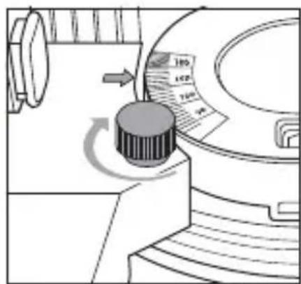
natural_image
Diagram of a mechanical device with a rotating knob and adjustment knob (no text or symbols)Fig. 4 Fig. 5
Fig.
6
natural_image
Technical line drawing of a mechanical assembly with no visible text or symbols
natural_image
Diagram of a vehicle interior showing a car with a moving component and directional arrow (no text or symbols)Fig. 7 Fig. 8
KOMPERNASS HANDELS GMBH
BURGSTRASSE 21
44867 BOCHUM
ALLEMAGNE
www.kompernass.com
Inhoud
Inleiding 32
natural_image
Technical diagram showing mechanical assembly with downward force and three bolted components (no text or symbols)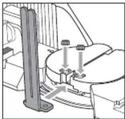
natural_image
Mechanical assembly diagram showing a rotating component with mounting holes and a vertical support (no text or symbols)
natural_image
Technical diagram of a vehicle dashboard with four buttons and a screwdriver inserted (no text or labels)natural_image
Three technical diagrams showing mechanical components and a control panel (no text or symbols present)Afb. 4 Afb. 5
Afb.
6
natural_image
Technical line drawing of a mechanical assembly with no visible text or symbols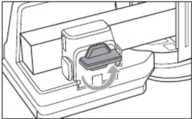
natural_image
Diagram of a vehicle door panel with a moving device and directional arrow indicating rotation (no text or symbols)Afb. 7 Afb. 8
Reinigen en opbergen
LET OP! MATERIËLE SCHADE!
KOMPERNASS HANDELS GMBH
BURGSTRASSE 21
44867 BOCHUM
DUITSLAND
www.kompernass.com
Obsah
Úvod 42
natural_image
Technical diagram showing mechanical assembly with downward force and three bolted components (no text or labels)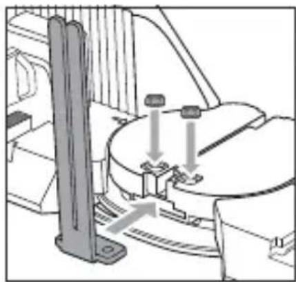
natural_image
Mechanical assembly diagram showing a rotating component with mounting brackets and a vertical support (no text or symbols)
natural_image
Technical diagram of a vehicle dashboard with no visible text or symbolsObr. 1 Obr. 2 Obr. 3
Použití
Měření úhlu
UPOZORNĚNÍ
natural_image
Three-panel technical illustration showing a mechanical assembly, a close-up of a device with a rotating knob, and a close-up of a component (no text or symbols)Obr. 4 Obr. 5
Obr. 6
natural_image
Technical line drawing of a mechanical clamp or bracket assembly (no text or symbols)Obr.
natural_image
Diagram of a vehicle interior showing a car trunk and dashboard with an arrow indicating rotation (no text or symbols present)7
Obr. 8
POZOR! HMOTNÉ ŠKODY!
KOMPERNASS HANDELS GMBH
BURGSTRASSE 21
44867 BOCHUM
NĚMECKO
www.kompernass.com
Spis treści
Wstep. 52
natural_image
Technical diagram showing mechanical assembly with downward force and three bolted components (no text or symbols)natural_image
Technical diagram of a mechanical assembly with no visible text or symbols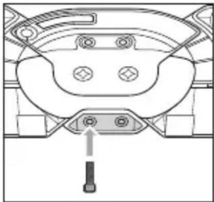
natural_image
Technical diagram of a mechanical component with mounting holes and a central connector (no text or symbols)Zastosowanie
Pomiar kątów
WSKAZÓWKA
natural_image
Three technical diagrams showing mechanical components and a rotating component (no text or symbols)Rys. 4 Rys. 5
Rys.
6
natural_image
Technical line drawing of a mechanical assembly with no visible text or symbols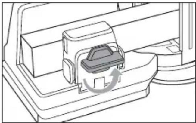
natural_image
Diagram of a mechanical device with a component inserted, showing a circular arrow indicating rotation (no text or symbols present)Rys. 7 Rys. 8
KOMPERNASS HANDELS GMBH
BURGSTRASSE 21
44867 BOCHUM
NIEMCY
www.kompernass.com
Obsah
Úvod 62
natural_image
Technical diagram showing a mechanical assembly with downward force arrows and a component (no text or symbols)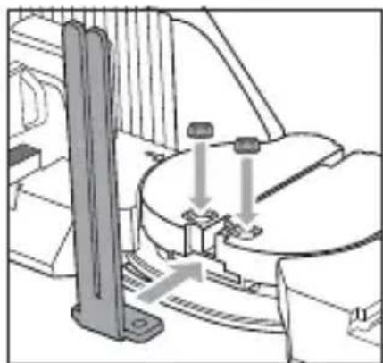
natural_image
Technical line drawing of a mechanical assembly with no visible text or symbols
natural_image
Technical diagram of a vehicle's rear dashboard and steering wheel (no text or symbols)Obr. 1 Obr. 2 Obr. 3
Použitie
Meranie uhla
UPOZORNENIE
natural_image
Three-panel technical illustration showing mechanical components and a rotary knob (no text or symbols)Obr. 4 Obr. 5
Obr.
6
natural_image
Technical line drawing of a mechanical assembly with no visible text or symbols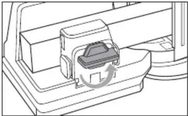
natural_image
Technical line drawing of a mechanical component with an arrow indicating rotation (no text or symbols)Obr. 7 Obr. 8
KOMPERNASS HANDELS GMBH
BURGSTRASSE 21
44867 BOCHUM
NEMECKO
www.kompernass.com
Índice
Introducción 72
natural_image
Technical diagram showing a mechanical assembly with a downward arrow and two bolted components below (no text or symbols)Fig. 1
natural_image
Technical diagram of a mechanical assembly with no visible text or symbolsFig. 2

natural_image
Technical diagram of a mechanical component with a bolt and adjustment knob (no text or symbols)Fig. 3
Utilización
Medición de ángulos
INDICACIÓN
natural_image
Technical line drawings of two mechanical components, one with internal structure and the other with external housing (no text or symbols)Fig. 4
natural_image
Diagram of a mechanical device with a rotating knob and a circular component, showing no text or symbols.Fig. 5
Fig. 6
natural_image
Technical line drawing of a mechanical assembly with no visible text or symbolsFig. 7

natural_image
Diagram of a vehicle door panel with a car slot and directional arrow indicating rotation (no text or symbols)Fig. 8
KOMPERNASS HANDELS GMBH
BURGSTRASSE 21
44867 BOCHUM
ALEMANIA
www.kompernass.com
Indholdsfortegnelse
Introduktion 82
natural_image
Technical diagram showing a mechanical assembly with a downward arrow and a component below (no text or symbols)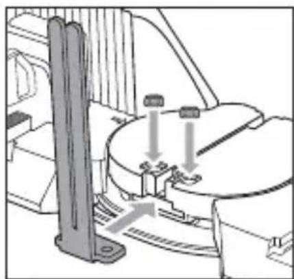
natural_image
Mechanical assembly diagram showing a cylindrical component with two downward arrows indicating motion or force, no text or symbols present.
natural_image
Technical diagram of a mechanical component with no visible text or symbolsnatural_image
Technical line drawing of a mechanical assembly with no visible text or symbols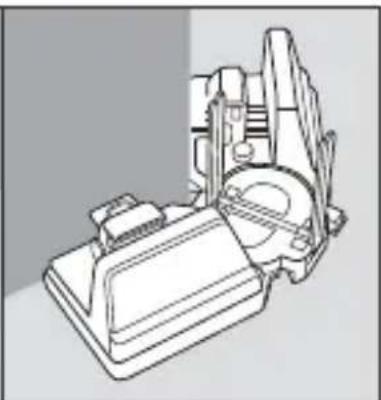
natural_image
Technical line drawing of a mechanical assembly (no text or symbols)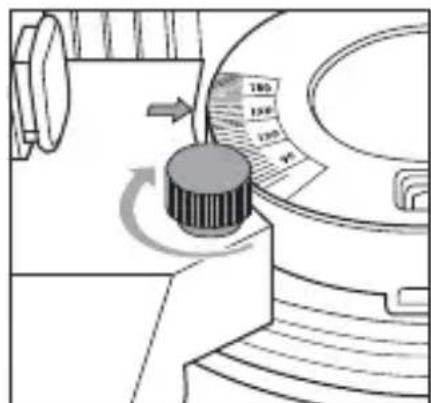
natural_image
Diagram of a mechanical device with a rotary knob and scale, showing motion direction (no text or symbols)Fig. 4 Fig. 5
Fig.
6
natural_image
Technical line drawing of a mechanical assembly with no visible text or symbols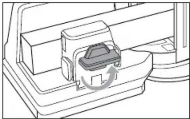
natural_image
Diagram of a mechanical device with a component inserted, showing a circular arrow indicating rotation (no text or symbols present)Fig. 7 Fig. 8
KOMPERNASS HANDELS GMBH
BURGSTRASSE 21
44867 BOCHUM
TYSKLAND
www.kompernass.com


KOMPERNASS HANDELS GMBH
BURGSTRASSE 21
44867 BOCHUM
GERMANY
www.kompernass.com
Last Information Update · Stand der Informationen · Version des informations
Stand van de informatie · Stav informací · Stan informacji · Stav informácií
Estado de las informaciones · Tilstand af information:
02 / 2021 · Ident.-No.: PSS2A1-012021-1
IAN 364230_2010
- Contents
- Introduction 2
- Safety 3
- Contents of package/parts description ..... 4
- Installation 5
- Use 6
- Cleaning and storage 8
- Disposal 9
- Service 10
- Importer 10
- Introduction
- Information about these operating instructions
- Proper use
- Safety
- Contents of package/parts description
- NOTE
- Installation
- Clamping and sawing a wooden workpiece
- Cleaning and storage
- ATTENTION! PROPERTY DAMAGE!
- Disposal
- Service
- Service Great Britain
- ServiceIreland
- Importer
- Inhaltsverzeichnis
- Einführung 12
- Table des matières
- Introduction 22
- Inhoud
- Inleiding 32
- Reinigen en opbergen
- LET OP! MATERIËLE SCHADE!
- Obsah
- Úvod 42
- Použití
- Měření úhlu
- UPOZORNĚNÍ
- POZOR! HMOTNÉ ŠKODY!
- Spis treści
- Wstep. 52
- Zastosowanie
- Pomiar kątów
- WSKAZÓWKA
- Úvod 62
- Použitie
- Meranie uhla
- UPOZORNENIE
- Índice
- Introducción 72
- Utilización
- Medición de ángulos
- INDICACIÓN
- Indholdsfortegnelse
- Introduktion 82
- KOMPERNASS HANDELS GMBH
Brand : PARKSIDE
Model : PSS 2 A1
Category : Tab box