
SDMN50R - Other computer accessories SONY - Free user manual and instructions
Find the device manual for free SDMN50R SONY in PDF.
| Product type | 15-inch LCD monitor with integrated stereo speaker |
| Brand | Sony |
| Model | SDM-N50R |
| Screen size | 15 inches (38 cm) |
| Maximum resolution | 1024 × 768 (XGA) |
| Horizontal frequency | 30 - 61 kHz |
| Vertical frequency | 48 - 85 Hz (only XGA at 75 Hz) |
| Video input signal | Analog RGB, 0.700 Vp-p, 75 ohms |
| Video input connectors | 2 × HD15 (RGB) |
| Audio output | Stereo speaker 2 W × 2 |
| Headphone jack | Stereo mini-jack (16 - 48 ohms) |
| Audio input | Stereo mini-jack, 0.5 Vrms |
| Power supply | 100 - 240 V, 50/60 Hz, 0.55 - 0.3 A |
| Power consumption (max) | 35 W |
| Standby consumption | ≤ 3 W |
| Dimensions (screen) | 356 × 347 × 185 mm |
| Dimensions (media engine with stand) | 94 × 185 × 180 mm |
| Weight (screen) | 2.7 kg |
| Weight (media engine with stand) | 0.85 kg |
| Main features | Auto image quality adjustment, brightness sensor, user detection sensor, power saving mode, adjustments contrast/brightness/phase/clock/centering/zoom/color temperature, multilingual OSD menu |
| Maintenance and cleaning | Unplug before cleaning; use a soft cloth; do not use solvents or abrasive products |
| Safety | Do not expose to extreme temperatures, humidity, dust; install near an accessible power outlet; do not block ventilation slots |
| Spare parts and repairability | Replaceable fluorescent tube (consult your Sony dealer); disposal according to local regulations (mercury) |
| Included accessories | Power cord, system connection cable (2 m), HD15 video cable, audio cable, Windows and Macintosh utility discs, user manual, warranty card |
Frequently Asked Questions - SDMN50R SONY
User questions about SDMN50R SONY
0 question about this device. Answer the ones you know or ask your own.
Ask a new question about this device
Download the instructions for your Other computer accessories in PDF format for free! Find your manual SDMN50R - SONY and take your electronic device back in hand. On this page are published all the documents necessary for the use of your device. SDMN50R by SONY.
USER MANUAL SDMN50R SONY
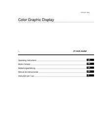
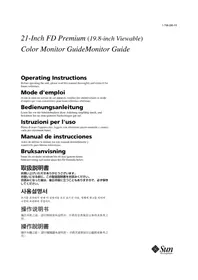
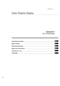
TFTLCD Color Computer Display
Operating Instructions GB
Mode d'emploi FR
Bedienungsanleitung DE
Manual de instrucciones ES
Istruzioni per l'uso IT
SDM-N50R
Owner's Record
The model and serial numbers are located at the rear of the unit. Record these numbers in the spaces provided below. Refer to them whenever you call upon your dealer regarding this product. Model No. __ Serial No. ____
WARNING
To prevent fire or shock hazard, do not expose the unit to rain or moisture.
Dangerously high voltages are present inside the unit. Do not open the cabinet. Refer servicing to qualified personnel only.
FCC Notice
This equipment has been tested and found to comply with the limits for a Class B digital device, pursuant to Part 15 of the FCC Rules. These limits are designed to provide reasonable protection against harmful interference in a residential installation. This equipment generates, uses, and can radiate radio frequency energy and, if not installed and used in accordance with the instructions, may cause harmful interference to radio communications. However, there is no guarantee that interference will not occur in a particular installation. If this equipment does cause harmful interference to radio or television reception, which can be determined by turning the equipment off and on, the user is encouraged to try to correct the interference by one or more of the following measures:
- Reorient or relocate the receiving antenna.
- Increase the separation between the equipment and receiver.
- Connect the equipment into an outlet on a circuit different from that to which the receiver is connected.
- Consult the dealer or an experienced radio/TV technician for help. You are cautioned that any changes or modifications not expressly approved in this manual could void your authority to operate this equipment.
NOTICE
This notice is applicable for USA/Canada only.
If shipped to USA/Canada, install only a UL LISTED/CSA
LABELLED power supply cord meeting the following specifications:
SPECIFICATIONS
Plug Type Nema-Plug 5-15p
Cord Type SVT or SJT, minimum 3-18 AWG
Length Maximum 15 feet
Rating Minimum 7 A, 125 V
NOTICE
As an ENERGY STAR Partner, Sony Corporation has determined that this product meets the ENERGY STAR guidelines for energy efficiency.

This monitor complies with the TCO'95 guidelines.
If you have any questions about this product, you may call:
Sony Customer Information Center
1-800-222-SONY (7669)
or write to:
Sony Customer Information Center
1 Sony Drive, Mail Drop #T1-11, Park Ridge, NJ 07656
Declaration of Conformity
Trade Name:
SONY
Model No.:
SDM-N50R
Responsible Party:
Sony Electronics Inc.
Address:
680 Kinderkamack Road, Oradell, NJ
07649 USA
Telephone No.:
201-930-6972
This device complies with Part 15 of the FCC Rules. Operation is subject to the following two conditions: (1) This device may not cause harmful interference, and (2) this device must accept any interference received, including interference that may cause undesired operation.
Table of Contents
Precautions. 4
To enjoy clear sound from the built-in stereo speaker 5 Identifying parts and controls.
Setup. 8
Step 1: Connect the media engine to your computer. 8
Step 2: Connect the display and media engine .8
Step 3: Connect the power cord. 9
Step 4: Turn on the monitor and computer 9
Using the stereospeaker 10
Selecting the input signal 10
Customizing Your Monitor
Navigatingthemenu. 11
Adjusting the contrast (CONTRAST)
Adjusting the black level of an image (BRIGHTNESS). 12
Eliminating flicker or blurring (PHASE/PITCH) 13
Adjusting the picture position (HCENTER/VCENTER)...
Displaying a low-resolution signal at the actual resolution
(ZOOM). 14
Adjusting the color temperature (COLOR) 14
Changing the menu's position (MENU POSITION) 14
Resetting the adjustments (RESET)
Additional settings (Option) 1
TechnicalFeatures 17
Macintosh is a trademark licensed to Apple Computer, Inc., registered in the U.S.A. and other countries.
- Windows - is registered trademark of Microsoft Corporation in the United States and other countries.
- IBM PC/AT and VGA are registered trademarks of IBM Corporation of the U.S.A.
VESA and DDC are trademarks of the Video Electronics Standards Association.
- ENERGY STAR is a U.S. registered mark.
- All other product names mentioned herein may be the trademarks or registeredTrademarksofttheir respective companies.
- Furthermore, "[]" and "["] are not mentioned in each case in this
Power saving function (user sensor/power saving mode) 17
Automatic brightness adjustment function (lightsensor
Automatic picture quality adjustment function 18
Troubleshooting 19
On-screen messages 19
Troublesymptomsandremedies. 20
Self-diagnosis function 22
Specifications 22
Appendix
- Presetmodetimingtable
TCO'95Eco-document.
Precautions
Warning on power connections
- Use the supplied power cord. If you use a different power cord, be sure that it is compatible with your local power supply.
For the customers in the U.S.A.
If you do not use the appropriate cord, this monitor will not conform to mandatory FCC standards.
For the customers in the UK
If youusethemonitorin theUK, please use the appropriate UK power cord.
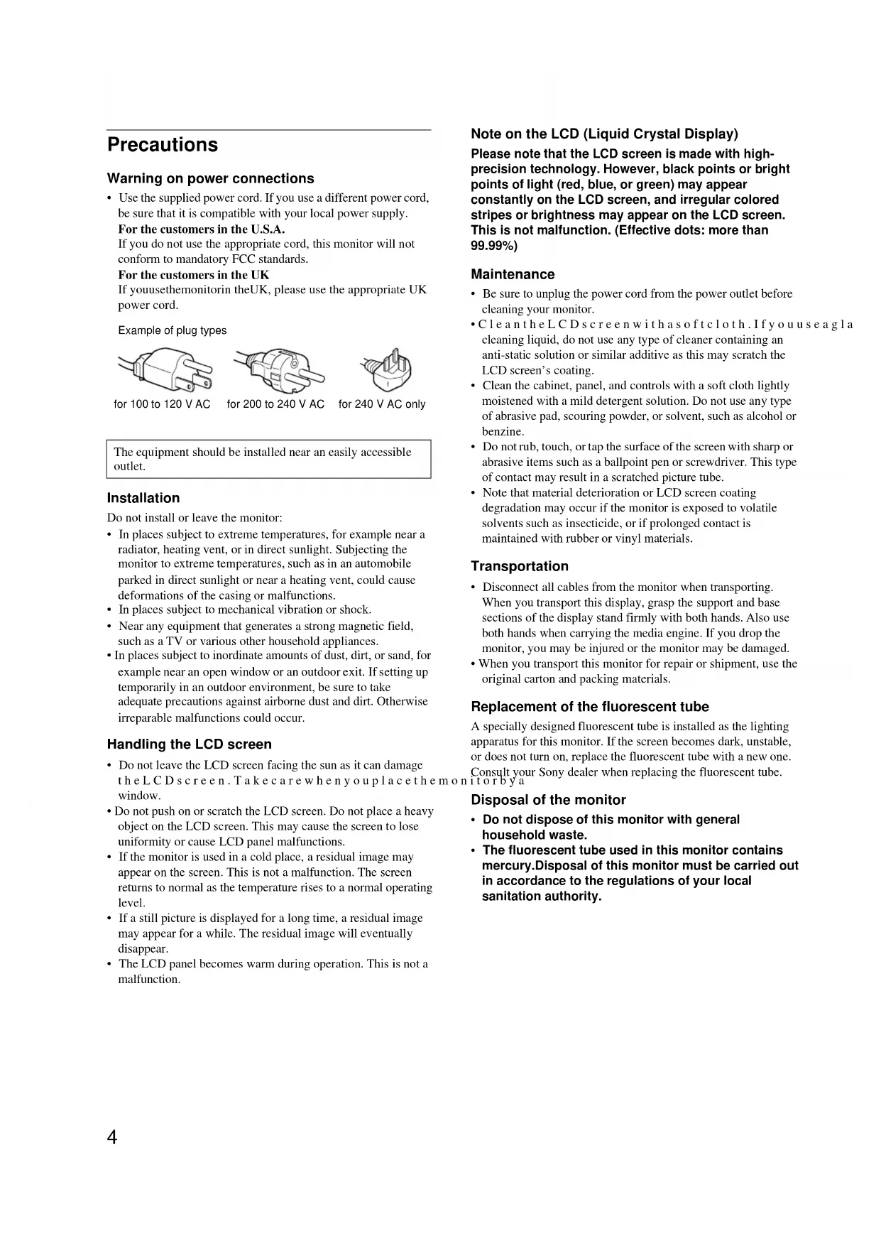
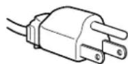
Example of plug types
for 100 to 120 V AC

for 200 to 240 V AC
for 240 V AC only
The equipment should be installed near an easily accessible outlet.
Installation
Do not install or leave the monitor:
- In places subject to extreme temperatures, for example near a radiator, heating vent, or in direct sunlight. Subjecting the monitor to extreme temperatures, such as in an automobile parked in direct sunlight or near a heating vent, could cause deformations of the casing or malfunctions.
- In places subject to mechanical vibration or shock.
- Near any equipment that generates a strong magnetic field, such as a TV or various other household appliances.
- In places subject to inordinate amounts of dust, dirt, or sand, for example near an open window or an outdoor exit. If setting up temporarily in an outdoor environment, be sure to take adequate precautions against airborne dust and dirt. Otherwise irreparable malfunctions could occur.
Handling the LCD screen
- Do not leave the LCD screen facing the sun as it can damage the LCD screen. Take care when you replace the window.
- Do not push on or scratch the LCD screen. Do not place a heavy object on the LCD screen. This may cause the screen to lose uniformity or cause LCD panel malfunctions.
- If the monitor is used in a cold place, a residual image may appear on the screen. This is not a malfunction. The screen returns to normal as the temperature rises to a normal operating level.
- If a still picture is displayed for a long time, a residual image may appear for a while. The residual image will eventually disappear.
- The LCD panel becomes warm during operation. This is not a malfunction.
Note on the LCD (Liquid Crystal Display)
Please note that the LCD screen is made with high-precision technology. However, black points or bright points of light (red, blue, or green) may appear constantly on the LCD screen, and irregular colored stripes or brightness may appear on the LCD screen. This is not malfunction. (Effective dots: more than 99.99% )
Maintenance
- Be sure to unplug the power cord from the power outlet before cleaning your monitor.
- Clean the LCD screen with a soft cloth. If you use a clean liquid, do not use any type of cleaner containing an anti-static solution or similar additive as this may scratch the LCD screen's coating.
- Clean the cabinet, panel, and controls with a soft cloth lightly moistened with a mild detergent solution. Do not use any type of abrasive pad, scouring powder, or solvent, such as alcohol or benzine.
- Do not rub, touch, or tap the surface of the screen with sharp or abrasive items such as a ballpoint pen or screwdriver. This type of contact may result in a scratched picture tube.
- Note that material deterioration or LCD screen coating degradation may occur if the monitor is exposed to volatile solvents such as insecticide, or if prolonged contact is maintained with rubber or vinyl materials.
Transportation
- Disconnect all cables from the monitor when transporting. When you transport this display, grasp the support and base sections of the display stand firmly with both hands. Also use both hands when carrying the media engine. If you drop the monitor, you may be injured or the monitor may be damaged.
- When you transport this monitor for repair or shipment, use the original carton and packing materials.
Replacement of the fluorescent tube
A specially designed fluorescent tube is installed as the lighting apparatus for this monitor. If the screen becomes dark, unstable, or does not turn on, replace the fluorescent tube with a new one. Consult your Sony dealer when replacing the fluorescent tube.
Disposal of the monitor
- Do not dispose of this monitor with general household waste.
- The fluorescent tube used in this monitor contains mercury. Disposal of this monitor must be carried out in accordance to the regulations of your local sanitation authority.
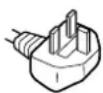
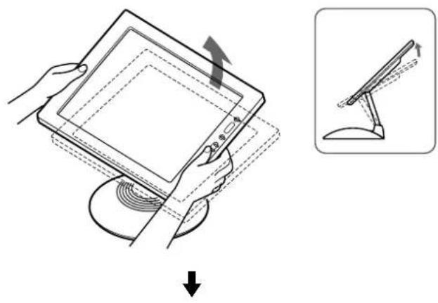
To adjust the tilt and height
This display can be adjusted within the angles shown below.
To adjust the angles, grasp the lower sides of the LCD panel with both hands as shown below. Tilt the LCD panel adequately backward, then lift the LCD panel upward to the desired screen height, then adjust the screen tilt as desired. When adjusting the screenheightandtilt,proceedslowlyandcarefully,beingsure not to hit the LCD panel against the desk or the base of the display stand.
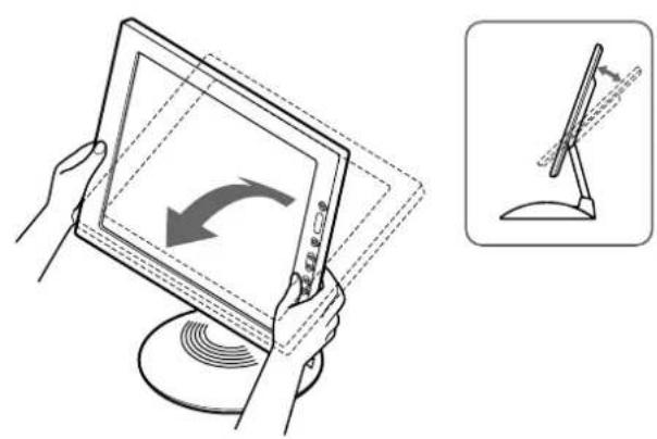
To use the display comfortably
This display is designed so that you can set it up at a comfortable viewing angle. Adjust the viewing angle of your display according to the height of the desk chair, and so that it not reflected from the screen to your eyes.
To enjoy clear sound from the built-in stereo speaker
This monitor has a built-in stereo speaker in base of the display stand.
We recommend that you position the LCD panel slightly away from the display stand. High tones from the speaker may be muffled if the LCD panel is positioned immediately on top of the stand. Be careful not to drop any metal object into the speaker's vents as the speakers generate a magnetic field. Also, this magnetic field may affect data stored on magnetic tapes and discs. Be sure to keep magnetic recording equipment, tapes, and floppy discs away from the speaker's opening.
A duct is provided on the rear part of the display stand to boost the bass. Be sure not to block the duct with paper or other objects to ensure clear sound.

Identifying parts and controls
See the pages in parentheses for further details.
LCD display
Front
Rear
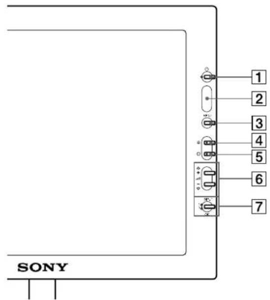
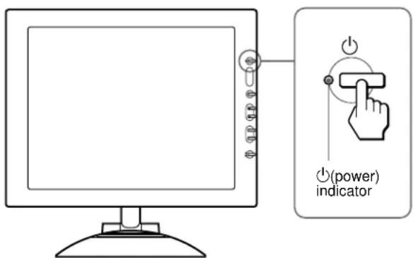
1 (Power) switch and indicator (pages 9, 17, 22)
This switch turns the display on and off.
Theindicatorlights up in greenwhenthemonitoristurned on.
The indicator flashes in green and orange when the monitor is in low power consumption mode, and lights up in orange when the monitor is in power saving mode.
2 Light sensor and user sensor (pages 16, 17, 18)
These sensors measure the brightness of the surrounding area and detect when a user becomes present in front of the screen. Be sure not to cover the sensor with papers, etc.
3 MENU button (page 12)
This button displays the main menu.
4 (contrast) button (page 12)
This button displays the CONTRAST menu.
5 (brightness) button (page 12)
This button displays the BRIGHTNESS menu.
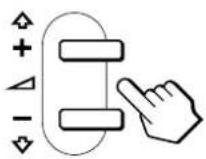
6 (volume) + / - and (+) / (-) buttons (pages 10, 12)
These buttons display the VOLUME menu and function as the (+) / (-) buttons when selecting the menu items and making adjustments.
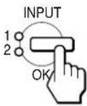
7 INPUT and OK button, and indicator (pages 10, 12)
This button selects the INPUT 1 or INPUT 2 (HD15 (RGB) connectors) video input signal. The input signal and corresponding input indicator change each time you press this button.
This button also functions as the OK button when displaying the menu on the screen.
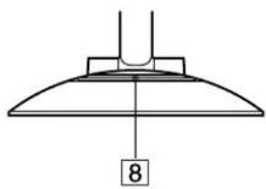
8 Stereo speaker (page 10)
This outputs the audio signals as sound.
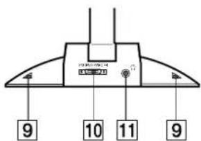
9Ducts
These are used to boost the bass sound from the speaker.
10 SYSTEM CONNECTOR (page 8)
Thisconnectorinputssignals fromthemediaenginewhenthe display and the media engine are connected with a system connecting cable.
11 Headphones jack (page 10)
This jack outputs audio signals to the headphones.
Media engine
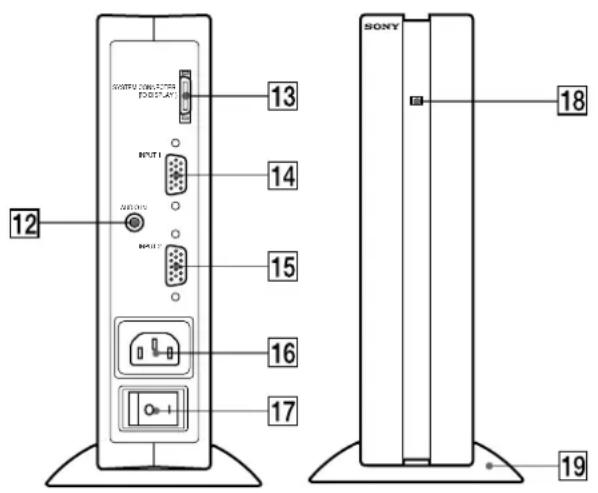
12 AUDIO IN jack (page 10)
This jack inputs audio signals when connecting to the audio output jack of the computer or other audio equipment.
13 SYSTEM CONNECTOR (TO DISPLAY) (page 8)
This connector outputssignalstothe displaywhen thedisplay and the media engine are connected with a system connecting cable.
14 HD15 (RGB) input 1 connector (INPUT1) (page 8)
This connector inputs RGB video signals (0.700 Vp-p, positive) and SYNC signals.
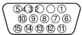
| Pin No. Signal | ||||
| 1 | Red | |||
| 2 Green (Sync on Green) | ||||
| 3 | B | l | u | e |
| 4 ID (Ground) | ||||
| 5 DDC Ground* | ||||
| 6 Red Ground | ||||
| 7 Green Ground | ||||
| 8 | B | l | u | e |
| 9 DDC + 5V* | ||||
| 10 Ground | ||||
| 11 ID (Ground) | ||||
| 12 Bi-Directional Data (SDA)* | ||||
| 13 H. Sync | ||||
| 14 V. Sync | ||||
| 15 Data Clock (SCL)* | ||||
- DDC (Display Data Channel) is a standard of VESA.
15 HD15 (RGB) input 2 connector (INPUT2) (page 8)
This connector inputs RGB video signals (0.700 Vp-p, positive) and SYNC signals. The pin assignment is the same as [14].
16 AC IN connector (page 9)
This connector provides AC power to the monitor.
17 AC power switch (page 9)
This switch turns the monitor on and off. Whenthe AC power switch is turned on, the display automatically turns on.
18 AC power indicator (page 17)
This indicator lights up in green when the media engine is turned on. The indicator lights up in red when the display is turned off with the media engine on. The indicator lights up in orange when the monitor is in the power saving mode.
19Media engine stand
This stand is used to install the media engine vertically.
Caution
Be sure to install the media engine vertically shown as left. Installing the media engine lying flat may block ventilation, and may cause a malfunction.
G r o u n d
Setup
Before using your monitor, check that the following items are included in your carton:
LCD display
Media engine
Mediaenginestand
Power cord
- System connecting cable (2 m)
(applicable cable type: DP-2)
HD15 (RGB) video signal cable
Audio cord (stereo miniplug)
- Windows Monitor Information Disk/Utility Disk
Macintosh Utility Disk
Warranty card
- This instruction manual
Step 1:Connect the media engine to your computer
Turn off the media engine and computer before connecting.
Note
Do not touch the pins of the video signal cable connector as this might bend the pins.
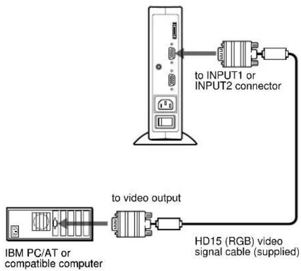
- Connecting to an IBM PC/AT or compatible computer
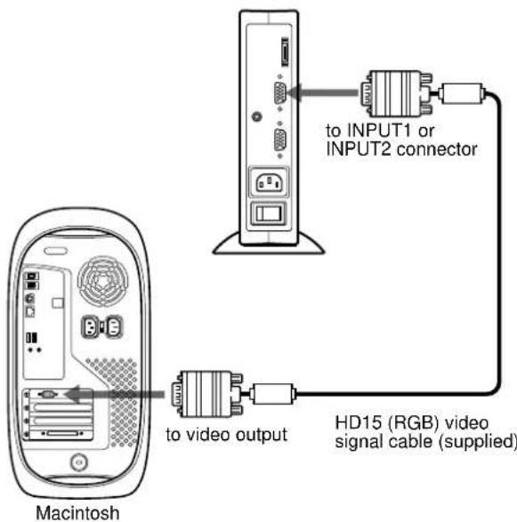
Connecting to a Macintosh
When connecting this monitor to a Macintosh computer, use the Macintosh adapter if necessary. Connect the Macintosh adapter to the computer before connecting the cable.
Step 2:Connect the display and media engine
Turn off the display and media engine before connecting.
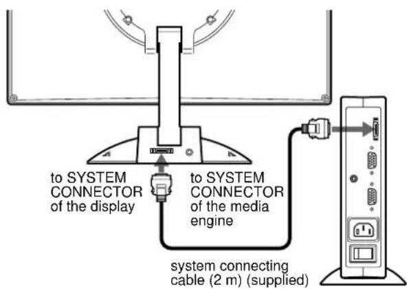
Caution
Be sure to install the media engine vertically as shown above. Installing the media engine lying flat may block ventilation, and may cause a malfunction.
Note
Grasp the plug when connecting the cable.
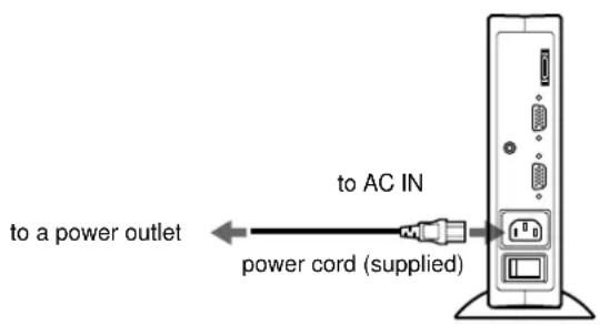
Step 3:Connect the power cord
With the media engine, display, and computer switched off, first connect the power cord to the media engine, then connect it to a power outlet.
Step 4: Turn on the monitor and computer
1 Turn on the media engine.
The display automatically turns on. The indicators of the media engine and display light up in green.
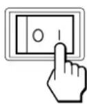
2 Turn on the computer.
The installation of your monitor is complete. If necessary, use the monitor's controls to adjust the picture.
If no picture appears on your screen
- Check that the monitor is correctly connected to the computer.
- Check that the media engine is on.
-
If NO INPUT SIGNAL appears on the screen, the computer is in the power saving mode. Try pressing any key on the keyboard or moving the mouse.
-
If CABLE DISCONNECTED appears on the screen, try changing the input signal (page 10), and check that the video input cable is properly connected.
- If OUT OF SCAN RANGE appears on the screen, reconnect the old monitor. Then adjust the computer's graphic board so that the horizontal frequency is between 30 - 61kHz , and the vertical frequency is between 48 - 85Hz (only XGA mode at 75Hz ).
For more information about the screen messages, see "Trouble symptoms and remedies" on page 20.
No need for specific drivers
The monitor complies with the "DDC" Plug & Play standard and automatically detects all the monitor's information. No specific driver needs to be installed to the computer.
The first time you turn on your computer after connecting the monitor, the setup Wizard may appear on the screen. In this case, follow the on-screen instructions. The Plug & Play monitor is automatically selected so that you can use this monitor.
The vertical frequency turns to 60Hz
Since flickers are unobtrusive on the monitor, you can use it as it is. You do not need to set the vertical frequency to any particular high value.
If your computer or graphics board has difficulty communicating with this monitor, install the information file for this monitor using the Windows Monitor Information Disk. For details on installing, refer to the ReadMe file on the disk.
Using the stereo speaker
You can listen to music, sounds, and other audio files using the stereospeaker of your monitor.
Connect the AUDIO IN jack to the audio output jack of your computer or other audio equipment using the supplied audio cord (stereo miniplug).
Adjusting the volume
Volume adjustments are made using a separate VOLUME menu from the main menu (page 11).
1 Press the + / - buttons.
The VOLUME menu appears on the screen.
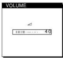
2 Press the + / - button to adjust the volume.
The menu automatically disappears after about 3 seconds.
Using the headphones jack
You can listen to the audio signals from your computer or other audio equipment using headphones. Connect your headphones to the headphones jack. The speaker turns off when headphones are connected to the headphones jack. Adjust the volume of the headphones using the VOLUME menu.
Notes
- You cannot adjust the volume when displaying the main menu on the screen.
- When your monitor is in low power consumption mode or power saving mode, no sound comes from the speaker.
Selecting the input signal
You can connect two computers to this monitor using the INPUT 1 and INPUT 2 connectors. To select one of the two computers, use the INPUT button.
Press the INPUT button.
The input signal and corresponding input indicator, "1" (INPUT 1) or "2" (INPUT 2) change each time you press this button.
Notes
- You cannot select the input signal when displaying the main menu on the screen.
- If no signal is input to the selected connector, NO INPUT SIGNAL or CABLE DISCONNECTED appearsonthescreen. After a few seconds, the monitor enters the power saving mode. If this happens, select the other connector using the INPUT button.
Customizing Your Monitor
Before making adjustments
Connect the monitor and the computer, and turn them on. Wait for at least 30 minutes before making adjustments for the best result.
You can make numerous adjustments to your monitor using the on-screen menu.
Navigating the menu
Press the MENU button to display the main menu on your screen.
Seepage12 formoreinformationonusingthemENUbutton.
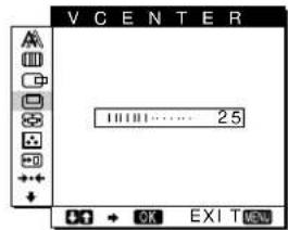
4V CENTER (page 13)
Select the V CENTER menu toadjustthepicture'svertical centering.
5ZOOM (page 14)
Select the ZOOM menu to adjustthe picture'sharpness according to the input signal's aspect ratio or resolution.
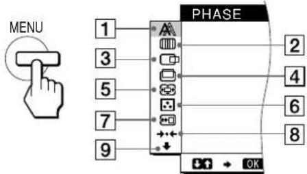
Use the (+)/ (-) and OK buttons to select one of the following menus. See page 12 for more information on using the (+)/ (-) and OK buttons.
6COLOR (page 14)
Select the COLOR menu to adjust the color temperature of the picture. This adjusts the tone of the screen.
7 MENU POSITION (page 14)
Select the MENU POSITION to change the onscreen menu position.
PHASE (page 13)
Select the PHASE menu to adjust the phase when the characters or pictures appear fuzzy throughout the entire screen. Adjust the phaseafter adjusting the pitch.
2PITCH (page 13)
Select the PITCH menu to adjust the pitch when the characters or pictures are unclear in some areas of the screen.
3H CENTER (page 13)
Select the H CENTER menu to adjust the picture's horizontal centering.
8RESET (page 15)
Select the RESET menu to reset the adjustments.
9Option (page 15)
Select (option) menu to adjust the monitor's options. The options include:
WIDE STEREO
BASS BOOST BACKLIGHT
- LIGHT SENSOR
- POWER SAVE
- USER SENSOR
LANGUAGE
-MENU LOCK
(continued)
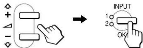
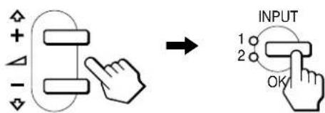
Using the MENU, (+) / (-) , and OK buttons
1 Display the main menu.
Press the MENU button to display the main menu on your screen.

2 Select the menu you want to adjust.
Press the (+) / (-) buttons to display the desired menu. Press the OK button to select the menu item.
3 Adjust the menu.
Press the (+) / (-) buttons to make the adjustment. Then press the OK button to return to the previous menu.
4 Close the menu.
Press the MENU button once to return to normal viewing. If no buttons are pressed, the menu closes automatically after about 30 seconds.

Resetting the adjustments
You can reset the adjustments using the RESET menu. See page 15 for more information on resetting the adjustments.
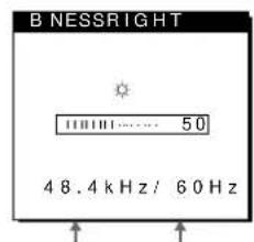
Adjusting the contrast (CONTRAST)
Contrast adjustment is made using a separate CONTRAST menu from the main menu (page 11). This setting is stored in memory for the signal from the currently selected input connector.
1 Press the (contrast) button.
The CONTRAST menu appears on the screen.
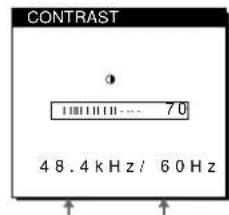
Horizontal frequency of the current input signal
Vertical frequency of the current input signal
Displaying the current input signal
The horizontal and vertical frequencies of the current input signal are displayed in the CONTRAST and BRIGHTNESS menu.
2 Press the (+) / (-) buttons to adjust the contrast.
The menu automatically disappears after about 3 seconds.
Adjusting the black level of an image (BRIGHTNESS)
Brightness adjustment is made using a separate BRIGHTNESS menu from the main menu (page 11). This setting is stored in memory for the signal from the currently selected input connector.
1 Press the (brightness) button.
The BRIGHTNESS menu appears on the screen.
Horizontal frequency of the current input signal
Vertical frequency of the current input signal
2 Press the (+) / (-) buttons to adjust the brightness.
The menu automatically disappears after about 3 seconds.
If the screen is too bright
Adjust the backlight. For more information about adjusting the backlight, see "Adjusting the backlight" on page 16.
Note
You can adjust neither contrast nor brightness when displaying the main menu on the screen.
Eliminating flicker or blurring (PHASE/PITCH)
When the monitor receives an input signal, the automatic picture quality adjustment function of this monitor automatically adjusts the picture position, phase, and pitch, and ensures that a clear picture appears on the screen. For more information about this function, see "Automatic picture quality adjustment function" on page 18.
For some input signals, this function may not completely adjust the picture position, phase, and pitch. In this case, you can manually set these adjustments according the following instructions. If you manually set these adjustments, they are stored in memory and automatically recalled whenever the monitor receives the same input signals.
The settings may have toberepeatedif you change the input signal after reconnecting your computer. To reset the automatic picture quality adjustment
1 Set the resolution to 1024 - 768 on the computer.
2 Load the Utility Disk.
Use the appropriate disk for your computer.
For Windows
Windows Monitor Information Disk/Utility Disk
For Macintosh
Macintosh Utility Disk
3 Start the Utility Disk and display the test pattern. For Windows
Click [Utility Disk] [Windows]/[Utility.exe].
For Macintosh
Click [Utility Disk] [SONY-Utility].
4 Press the MENU button.
The main menu appears on the screen.
5 Press the (+) / (-) buttons to select (PITCH) and press the OK button.
The PITCH menu appears on the screen.
6 Press the (+) / (-) buttons until the screen color becomes uniform.
Adjust so that the vertical stripes disappear.
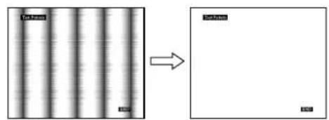
7 Press the OK button.
The main menu appears on the screen.
If horizontal stripes are observed over the entire screen, adjust the phase as the next step.
8 Press the (+) / (-) buttons to select A (PHASE) and press the OK button.
The PHASE menu appears on the screen.
9 Press the (+) / (-) buttons until the screen color becomes uniform.
Adjust so that the horizontal stripes are at a minimum.
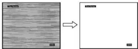
- Click END on the screen to turn off the test pattern.
To reset the automatic picture quality adjustment
Select SCREEN RESET and activate it using the RESET menu. See page 15 for more information on using the RESET menu.
Adjusting the picture position (H CENTER/V CENTER)
If the picture is not in the center of the screen, adjust the picture's centering as follows.
These settings may have to be repeated if you change the input signal after reconnecting your computer.
1 Start the Utility Disk and display the test pattern.
Repeat steps 2 and 3 of "Eliminating flicker or blurring (PHASE/PITCH)."
2 Press the MENU button.
The main menu appears on the screen.
3 Press the (+) / (-) buttons to select (H CENTER) or (V CENTER) and press the OK button.
The H CENTER or V CENTER menu appears on the screen.
4 Move the picture up, down, left, or right until the frame at the perimeter of the test pattern disappears.
Press the (+) / (-) buttons to adjust the picture's centering using the H CENTER menu for horizontal adjustment, or the V CENTER menu for vertical adjustment.
5 Click END on the screen to turn off the test pattern.
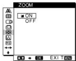
Displaying a low-resolution signal at the actual resolution (ZOOM)
This monitor is preset at the factory to display pictures on the screen in full, irrespective of the picture's mode or resolution. You can also view the picture at its actual resolution.
1 Press the MENU button.
The main menu appears on the screen.
2 Press the (+) / (-) buttons to select (ZOOM) and press the OK button.
The ZOOM menu appears on the screen.
3 Press the (-) button to select OFF.
The input signal is displayed on the screen at its actual resolution.
To display the picture on the screen in full

Select ON in step 3.
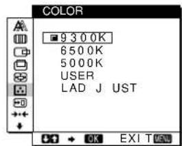
Adjusting the color temperature (COLOR)
The COLOR settings allow you to adjust the picture's color temperature by changing the color level of the white color field.
Colors appear reddish if the temperature is low, and bluish if the temperature is high.
9300K is generally suitable for word processing and other text oriented applications, and 6500K is generally suitable for video images.
You can set the color temperature to 5000K, 6500K, 9300K or user adjustment.
1 Press the MENU button.
The main menu appears on the screen.
2 Press the (+) / (-) buttons to select (COLOR) and press the OK button.
The COLOR menu appears on the screen.
3 Press the (+) / (-) buttons to select the desired color temperature.
The preset colortemperatures are 5000K, 6500K, and 9300K. Since the default setting is 9300K, the whites will change from a bluish hue to a reddish hue as the temperature is lowered to 6500 K and 5000 K.
You can set separate color temperatures for each of the video input signals.
4 If necessary, fine tune the color temperature.
First press the (+) / (-) buttons to select L ADJUST and press the OK button. Then press the (+) / (-) buttons to select R (Rcd) or B (Blue) and press the OK button, and then press the (+) / (-) buttons to adjust the color temperature.
Since this adjustment changes the color temperature by increasing or decreasing the R and B components with respect to G (green), the G component is fixed.
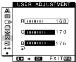
If you fine tune the color temperature, the new color setting is stored in memory for USER ADJUSTMENT and automatically recalled whenever USER is selected.
The USER ADJUSTMENT setting is common to both the input signals. If you change the user adjustment setting for one input signal, the setting for the other input signal is also changed.
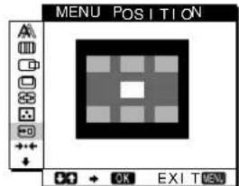
Changing the menu's position (MENU POSITION)
You can change the menu position if it is blocking an image on the screen.
1 Press the MENU button.
The main menu appears on the screen.
2 Press the (+) / (-) buttons to select (MENU POSITION) and press the OK button.
The MENU POSITION menu appears on the screen.
3 Press the (+) / (-) buttons to select the desired position.
There are three positions each for the top of the screen and the bottom of the screen, and one for the screen center.
Resetting the adjustments (RESET)
This monitor has the following two reset methods. Use the RESET menu to reset the adjustments.
1 Press the MENU button.
The main menu appears on the screen.
2 Press the (+)/ (-) buttons to select (RESET) and press the OK button.
The RESET menu appears on the screen.
Reset the settings according to the following instructions.
Resetting the adjustment data most appropriately for the current input signal
Press the (+) / (-) buttons to select SCREEN RESET and press the OK button.
The automatic picturequality adjustment function of this monitor automatically adjusts the picture position, phase, and pitch, to the most appropriate value. If this function is activated, the phase is automatically adjusted whenever the monitor receives the same input signal.
The RESET menu is automatically returned to the main menu after the adjustment data is reset.
Resetting all of the adjustment data for all input signals
Press the (+) / (-) buttons to select ALL RESET and press the OK button.
The RESET menu is automatically returned to the main menu after the adjustment data is reset.
To cancel resetting
Press the (+) / (-) buttons to select and press the OK button.
The RESET menu returns to the main menu without resetting the adjustment data.
Additional settings (Option)
You can adjust the following options:
WIDE STEREO
BASS BOOST
- BACKLIGHT
- LIGHT SENSOR
- POWER SAVE
- USER SENSOR
LANGUAGE
-MENU LOCK
1 Press the MENU button.
The main menu appears on the screen.
2 Press the (+) / (-) buttons to select
The option menu appears on the screen.
3 Press the (+) / (-) buttons to select the desired option item and press the OK button.
Adjust the selected option item according to the following instructions.
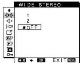
Increasing the soundscape (wide stereo function)
This adjustment makes use of the DSP and creates the illusion of the built-in stereo speaker being further away than it actually is, thus enhancing sound presence.
First press the (+) / (-) buttons to select (WIDE STEREO) and press the OK button. Then press the (+) / (-) buttons to select either 2, 1, or OFF.
The wide stereo function is used to increase the soundscape. Selecting 1 or 2 increases incrementally the soundscape effect toward the front of the monitor.
Notes
- If your connected computer or audio equipment uses special sound functions, such as surround sound, be sure to turn these functions off. If these functions are being used with the wide stereo function of this monitor, the wide stereo function may not function properly and thus not produce the desired sound effect.
- This function is automatically turned off when you use headphones. However, in this case, the indication in the WIDE STEREO menu does not change.
- The wide stereo function allows you to increase the soundscape by converting the analog signals into digital. The sound may be distorted depending on the input signal and music. In this case, decrease the volume or set the wide stereo function to OFF.
Boosting the bass (bass boost function)
This option increases the bass output of the speaker. First press the (+) / (-) buttons to select + (BASS BOOST) and press the OK button. Then press the (+) / (-) buttons to select either ON or OFF.
(continued)
Adjusting the backlight
If the screen is too bright, adjust the backlight.
First press the (+) / (-) buttons to select
(BACKLIGHT) and press the OK button. Then press the (+)/ (-) buttons to adjust the desired light level.
Automatically adjusting the screen brightness (light sensor)
This monitor is provided with a sensor to detect the brightness of the surrounding area (light sensor). This sensor is used to automatically adjust the brightness of the screen.
First press the (+) / (-) buttons to select (LIGHT SENSOR) and press the OK button. Then press the (+) / (-) buttons to select either ON or OFF.
When you select ON, the monitor automatically adjusts the screen brightness according to the brightness of the surroundings. For more information about this function, see "Automatic brightness adjustment function (light sensor)" on page 18.
Note
If this function is set to ON, the value of the BACKLIGHT menu does not change. If the screen brightness is still not appropriate after the automatic adjustment, you can manually adjust the backlight. After the backlight adjustment is made, the monitor automatically adjusts the screen brightness in accordance with the new backlight value.
Setting up the power saving mode
This monitor has a function which enables it to enter the power save mode automatically according to the power saving settings of the computer. You can prevent the monitor from entering the power saving mode by setting the following option to OFF.
First press the (+) / (-) buttons to select (POWER SAVE) and press the OK button. Then press the (+) / (-) buttons to select either ON or OFF.
Using the user sensor
The user sensor function enables the monitor to enter the low power consumption mode when no one is present in front of the monitor.
First press the (+) / (-) buttons to select (USER SENSOR) and press the OK button. Then press the (+) / (-) buttons to select either ON or OFF.
If you select ON, the monitor automatically enters the low power consumption mode when you move away from the front of the monitor. For more information about the low power consumption mode, see "Power saving function (user sensor/power saving mode)" on page 17.
Selecting the on-screen menu language
English, German, French, Spanish, Italian and Japanese versions of the on-screen menus are available. The default setting is English.
First press the (+) / (-) buttons to select (LANGUAGE) and press the OK button. Then press the (+) / (-) button to select a language.
- ENGLISH
- DEUTsCH: German
FRANÇAIS: French - ESPANOL: Spanish
ITALIANO:Italian
·:日本语ese
Locking the menus and controls
You can protect adjustment data by locking the menus and controls.
First press the (+)/ (-) buttons to select ON (MENU LOCK) and press the OK button. Then press the (+)/ (-) buttons and select ON.
Only the (power) switch, and (MENU LOCK) of the option menu will operate. If any other items are selected, thom mark appears on the screen.
To cancel the menu lock
Repeat the procedure above and set Om (MENULOCK) to OFF.
Technical Features
Power saving function (user sensor/power saving mode)
This monitor meets the power-saving guidelines set by VESA, ENERGY STAR, and NUTEK. If the monitor is connected to a computer or video graphics board that is DPMS (Display Power Management Signaling) compliant, the monitor will automatically enter the power saving mode. It automatically enters the low power consumption mode when the user sensor detects the absence of a user.
| Power consumption state | Power consumption | AC power indicator | ( power) indicator |
| normal operation | 35 W | green | green |
| 1 low power consumption mode | ≤8 W | green | green and orange alternate |
| 2 power saving mode | ≤3 W | orange | orange |
| ( power): off | ≤3 W | red | off |
| AC power: off | 0 W | off | off |
1 Low power consumption mode (user sensor)
When the user sensor in the monitor detects the absence of a user, the monitor enters low power consumption mode after about 20 seconds. In low power consumption mode, the monitor is in a power saving state and shuts off power to all circuitry (except for that of the sensors) regardless of the setting of the computer. The monitor returns to normal operation mode when the presence of a user is detected by the user sensor.
When the monitor enters the power saving mode (as set according to the computer's settings), the power saving mode takes precedence over the low power consumption mode. In this case, the monitor stays in the power saving mode regardless of the presence or absence of a user.
To return the monitor to normal operation mode, reset the computer's power saving mode.
Note
The user sensor detects the presence/absence of a user up to a distance of approximately 60~cm from the screen surface. However, this distance may vary depending on the user's clothes or the brightness of the surrounding area. If user detection fails due to the ambient conditions of the surrounding area, set the user sensor to OFF. If your monitor does not automatically return fromlow power consumption mode due to the failure of the user sensor to detect the presence of a user, press the (power) switch twice to turn the monitor off and then on.
2 Power saving mode
DPMS defines the active off state according to the state of the sync signals supplied from the computer. This monitor's power consumption is input at approximately 3W or less in this state if the power saving function is set to ON.
When your computer enters the power saving mode, the input signal is cut and NO INPUT SIGNAL appears on the screen. After a few seconds, the monitor enters power saving mode.
| Power saving state | Sync signal state |
| active off (deep sleep)* | horizontal: off / vertical: off |
- "Deep sleep" is a power saving mode defined by the Environmental Protection Agency.
Note
The power saving function may not work normally depending on the pattern of supplied sync signals. In such a case, set the power saving function to OFF.
Automatic brightness adjustment function (light sensor)
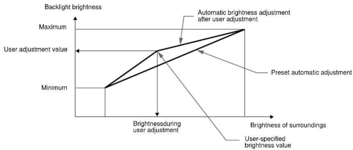
This monitor is provided with a feature to automatically adjust the screen brightness according to the brightness of the surroundings. The brightness of the backlight is set to the most appropriate level by setting the light sensor to ON. The default setting of the brightness of the backlight is set to its maximum. When the light sensor setting is set to ON, the monitor adjusts the brightness of the backlight linearly from its lower- to upper-limit values. When the user adjusts the backlight, the backlight brightness is automatically adjusted between the user adjustment value and the upper- and lower-limit values.
Automatic picture quality adjustment function
When the monitor receives an input signal, it automatically matches the signal to one of the factory preset modes stored in the monitor's memory to provide a high quality picture at the center of the screen. (See Appendix for a list of the factory preset modes.)
For input signals that do not match one of the factory preset modes, the automatic picture quality adjustment function of this monitor automatically adjusts the picture position, phase, and pitch, and ensures that a clear picture appears on the screen for any timing within the monitor's frequency range (horizontal: 30 - 61kHz , vertical: 48 - 85Hz ).
Consequently, the first time the monitor receives input signals that do not match one of the factory preset modes, the monitor may take a longer time than normal for displaying the picture on the screen. This adjustment data is automatically stored in memory so that next time, the monitor will function in the same way as when the monitor receives the signals that match one of the factory preset modes.
In all modes as above, if the picture is adjusted, the adjustment data is stored as a user mode and automatically recalled whenever the same input signal is received.
Note on the adjusting the phase
If the automatic picture quality adjustment function is activated, the picture moves slightly whenever the monitor receives the input signal, regardless of the stored adjustment.
Note
While the automatic picture quality adjustment function is activated, only the (power) switch, and INPUT button will operate.
Troubleshooting
Before contacting technical support, refer to this section.
On-screen messages
If there is something wrong with the input signal, one of the following messages appears on the screen. To solve the problem, see "Trouble symptoms and remedies" on page 20.
If OUT OF SCAN RANGE appears on the screen
This indicates that the input signal is not supported by the monitor's specifications. Check the following items.
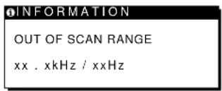
If "xx.x kHz/xx Hz" is displayed
This indicates that either the horizontal or vertical frequency is not supported by the monitor's specifications.
The figures indicate the horizontal and vertical frequencies of the current input signal. The horizontal frequencies above 100kHz and the vertical frequencies above 100Hz are represented by 99.9kHz and 99Hz , respectively.
If “RESOLUTION > XGA” is displayed
This indicates that the resolution is not supported by the monitor's specifications.
If NO INPUT SIGNAL appears on the screen
This indicates that no signal is input, or that no signal is input from the currently selected connector.
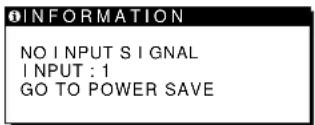
INPUT:
This indicates the currently selected connector (INPUT: 1 or INPUT: 2).
GO TO POWER SAVE
The monitor will enter the power saving mode after about 4 seconds from the message is displayed.
If CABLE DISCONNECTED appears on the screen
This indicates that the video signal cable has been disconnected from the currently selected connector.
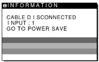
INPUT:
This indicates the currently selected connector (INPUT: 1 or INPUT: 2).
GO TO POWER SAVE
The monitor will enter the power saving mode after about 4 seconds from the message is displayed.
Trouble symptoms and remedies
If a problem is caused by the connected computer or other equipment, please refer to the connected equipment's instruction manual.
Use the self-diagnosis function (page 22) if the following recommendations do not resolve the problem.
| Symptom Check these items | |
| No picture | |
| If the AC power indicator is not lit | ·Check that the power cord is properly connected. |
| If the AC power indicator is red | ·Check that the (1) (power) switch is in the “on” position. |
| The AC power indicator is flashing red | ·Check that the system connecting cable is properly connected and all plugs are firmly seated in their sockets (page 8). ·Press the AC power switch twice to turn the monitor off and then on. |
| If the (1) (power) indicator is not lit, or if the (1) (power) indicator will not light up when the (1) (power) switch is pressed | ·Check that the (1) (power) switch is in the “on” position. ·Check that the AC power switch is in the “on” position. ·Check that the system connecting cable is properly connected and all plugs are firmly seated in their sockets (page 8). |
| If the (1) (power) indicator is green or flashing orange | ·Use the self-diagnostics function (page 22). |
| If the (1) (power) indicator is alternating between green and orange | ·The monitor cannot return from low power consumption mode because the user sensor fails to detect the presence of a user. Press the (1) (power) switch twice to turn the monitor off and then on. If you set the user sensor to OFF, the monitor does not enter low power consumption mode (page 16). |
| If CABLE DISCONNECTED appears on the screen | ·Check that the video signal cable is properly connected and all plugs are firmly seated in their sockets (page 8). ·Check that the input select setting is correct (page 10). ·Check that the video input connector's pins are not bent or pushed in. ·A non-supplied video signal cable is connected. If you connect a non-supplied video signal cable, CABLE DISCONNECTED appears on the screen before entering the power saving mode. This is not a malfunction. |
| If NO INPUT SIGNAL appears on the screen, or the (1) (power) indicator is orange | ·Check that the video signal cable is properly connected and all plugs are firmly seated in their sockets (page 8). ·Check that the input select setting is correct (page 10). ·Check that the video input connector's pins are not bent or pushed in. ■Problems caused by the connected computer or other equipment ·The computer is in the power saving mode. Try pressing any key on the keyboard or moving the mouse. ·Check that the computer's power is “on.” |
| If OUT OF SCAN RANGE appears on the screen | ■Problems caused by the connected computer or other equipment ·Check that the video frequency range is within that specified for the monitor. If you replaced an old monitor with this monitor, reconnect the old monitor and adjust the frequency range to the following: Horizontal: 30 - 61 kHz, Vertical frequency: 48 - 85 Hz (only XGA mode at 75 Hz) |
| If using Windows | ·If you replaced an old monitor with this monitor, reconnect the old monitor and do the following. Install the Windows Monitor Information Disk (page 9) and select this monitor (“SDM-N50R”) from among the Sony monitors in the Windows monitor selection screen. |
| If using a Macintosh system | ·Check that the Macintosh adapter (not supplied) and the video signal cable are properly connected. |
| Symptom | Check these items |
| Picture flickers, bounces, oscillates, or is scrambled | ·Adjust the pitch and phase (page 13).·Isolate and eliminate any potential sources of electric or magnetic fields such as other monitors, laser printers, electric fans, fluorescent lighting, or televisions.·Move the monitor away from power lines or place a magnetic shield near the monitor.·Try plugging the monitor into a different AC outlet, preferably on a different circuit.■Problems caused by the connected computer or other equipment·Check your graphics board manual for the proper monitor setting.·Confirm that the graphics mode (VESA, Macintosh 19" Color, etc.) and the frequency of the input signal are supported by this monitor (Appendix). Even if the frequency is within the proper range, some video boards may have a sync pulse that is monitor to sync correctly.·Adjust the computer's refresh rate (vertical frequency) to obtain the best possible picture. |
| Picture is fuzzy | ·Adjust the brightness and contrast (page 12).·Adjust the pitch and phase (page 13). |
| Picture is ghosting | ·Eliminate the use of video cable extensions and/or video switch boxes.·Check that all plugs are firmly seated in their sockets. |
| Picture is not centered or sized properly | ·Adjust the pitch and phase (page 13).·Adjust the picture position (page 13). Note that some video modes do not fill the screen to the edges. |
| Picture is too small | ·Set the zoom setting to ON (page 14).■Problems caused by the connected computer or other equipment·Set the computer's resolution to the screen's resolution. |
| Wavy or elliptical pattern (moire) is visible | ·Adjust the pitch and phase (page 13). |
| Color is not uniform | ·Adjust the pitch and phase (page 13). |
| White does not look white | ·Adjust the color temperature (page 14). |
| Monitor buttons do not operate (○n appears on the screen) | ·If the menu lock is set to ON, set it to OFF (page 16). |
| The monitor turns off after a while | ·Set the power saving function to OFF (page 16).·Set the user sensor to OFF (page 16).■Problems caused by the connected computer or other equipment·Set the computer's power saving setting to off. |
Displaying this monitor's name, serial number, and date of manufacture
While the monitor is receiving a video signal, press and hold the MENU button for more than 5 seconds to display this monitor's information box.
If any problem persists, call your authorized Sony dealer and give the following information:
- Model name: SDM-N50R
- Serial number
- Name and specifications of your computer and graphics board

Example
1 INFORMATION
MODEL :SDM-N50R
SER NO:1234567
MANUFACTURED:2001-52
Model name
Serial number
Week and year
of manufacture
Self-diagnosis function
This monitorisequipped with a self-diagnosis function. If there is a problem with your monitor or computer(s), the screen will go blank and the (power) indicator will either light up green or flash orange. If the (power) indicator is lit in orange, the computer is in power saving mode. Try pressing any key on the keyboard or moving the mouse.
If the 心 (power) indicator is green
1 Turn off the AC power switch and disconnect the video signal cables from the INPUT1 and INPUT2 connectors of the media engine.
2 Press the AC power switch twice to turn the monitor off and then on.
If all four color bars appear (white, red, green, blue), the monitor is working properly. Reconnect the video input cables and check the condition of your computer(s).
If the color bars do not appear, there is a potential monitor failure. Inform your authorized Sony dealer of the monitor's condition.
If the (power) indicator is flashing orange
Press the (power) switch twice to turn the monitor off and then on.
If the (power) indicator lights up green, the monitor is working properly.
If the (power) indicator is still flashing, there is a potential monitor failure. Count the number of seconds between orange flashes of the (power) indicator and inform your authorized Sony dealer of the monitor's condition. Be sure to note the model name and serial number of your monitor. Also note the make and model of your computer and graphic board.
Specifications
LCD panel Panel type: a-Si TFT Active Matrix
Picture size: 15 inch (38 cm)
Input signal format RGB operating frequency*
Horizontal: 30 - 61kHz
Vertical: 48 - 85Hz
(only XGA mode at 75Hz )
Resolution Horizontal: Max.1024 dots
Vertical: Max.768 lines
Input signal levels RGB video signal
0.700 Vp-p, 75 Ω, positive
SYNC signal
TTL level, 2k
positive or negative
(Separate horizontal and vertical,
or composite sync)
0.3 Vp-p, 75 negative
(Sync on green)
Audio output 2W·2
Headphones jack Stereo minijack
Accepts impedance of 16-48Ω
AUDIO IN jack Stereo minijack
Accepts impedance of 47k
Accepts level 0.5 Vrms
Power requirements 100-240 V, 50-60 Hz, 0.55-0.3 A
Power consumption Max. 35 W
Operating temperature 5-35°C
Dimensions (width/height/depth)
Display (upright):
Approx. 356 - 347 - 185 mm
(14^1 / 8· 13^3 / 4· 7^3 / 8 inches)
Media engine (without stand):
Approx. 45· 180· 180mm
(1^13 / 16 · 7^1 / 8 · 7^1 / 8 inches)
Media engine (with stand):
Approx. 94 · 185 · 180 mm
(3 3/4·7 3/8·7 1/8 inches)
Mass Display:
Approx. 2.7kg 5 lb 15 oz)
Media engine (with stand):
Approx. 0.85kg (1 lb 14 oz)
Plug & Play DDC2B/DDC2Bi
Accessories See page 8.
- Recommended horizontal and vertical timing condition
Horizontal sync width duty should be more than 4.8% of total horizontal time or 0.8~ s whichever is larger.
Horizontal blanking width should be more than 2.5 sec
Vertical blanking width should be more than 450~ sec
Design and specifications are subject to change without notice.
Table des matieres
Précautions. 4
Specifications techniques
(Horizontal y vertical
(sensoredellaluce) 18
VAI A RISPARMIO ENER.
VAI A RISPARMIO ENER.
Plug & Play DDC2B/DDC2Bi
Congratulations!
You have just purchased a TCO'95 approved and labelled product! Your choice has provided you with a product developed for professional use. Your purchase has also contributed to reducing the burden on the environment and also, to the further development of environmentally adapted electronics products.
Why do we have environmentally labelled computers?
In many countries, environmental labelling has become an established method for encouraging the adaptation of goods and services to the environment. The main problem, as far as computers and other electronics equipment are concerned, is that environmentally harmful substances are used both in the products and during the manufacturing. Since it has not been possible for the majority of electronics equipment to be recycled in a satisfactory way, most of these potentially damaging substances sooner or later enter Nature.
There are also other characteristics of a computer, such as energy consumption levels, that are important from the viewpoints of both the work (internal) and natural (external) environments. Since all methods of conventional electricity generation have a negative effect on the environment (acidic and climate-influencing emissions, radioactive waste, etc.), it is vital to conserve energy. Electronics equipment in offices consume an enormous amount of energy since they are often left running continuously.
What does labelling involve?
This product meets the requirements for the TCO'95 scheme which provides for international and environmental labelling of personal computers. The labelling scheme was developed as a joint effort by the TCO (The Swedish Confederation of Professional Employees), Naturskyddsforeningen (The Swedish Society for Nature Conservation) and NUTEK (The National Board for Industrial and Technical Development in Sweden). The requirements cover a wide range of issues: environment, ergonomics, usability, emission of electrical and magnetic fields, energy consumption and electrical and fire safety.
(continued)
The environmental demands concern restrictions on the presence and use of heavy metals, brominated and chlorinated flame retardants, CFCs (freons) and chlorinated solvents, among other things. The product must be prepared for recycling and the manufacturer is obliged to have an environmental plan which must be adhered to in each country where the company implements its operational policy.
The energy requirements include a demand that the computer and/or display, after a certain period of inactivity, shall reduce its power consumption to a lower level in one or more stages. The length of time to reactivate the computer shall be reasonable for the user.
Labelled products must meet strict environmental demands, for example, in respect of the reduction of electric and magnetic fields, physical and visual ergonomics and good usability.
On this page, you will find a brief summary of the environmental requirements met by this product. The complete environmental criteria document may be ordered from:
TCO Development Unit
S-114 94 Stockholm
Sweden
Fax: +46 8 782 92 07
Email (Internet): development@tco.se
Current information regarding TCO'95 approved and labelled products may also be obtained via the Internet, using the address:
http://www.tco-info.com/
TCO'95 is a co-operative project between TCO (The Swedish Confederation of Professional Employees),
Naturskyddsforeningen (The Swedish Society for Nature
Conservation) and NUTEK (The National Board for Industrial and Technical Development in Sweden).
Environmental Requirements
Brominated flame retardants
Brominated flame retardants are present in printed circuit boards, cables, wires, casings and housings. In turn, they delay the spread of fire. Up to thirty percent of the plastic in a computer casing can consist of flame retardant substances. These are related to another group of environmental toxins, PCBs, which are suspected to give rise to similar harm, including reproductive damage in fisheating birds and mammals, due to the bio-accumulative* processes.
Flame retardants have been found in human blood and researchers fear that disturbances in foetus development may occur.
TCO'95 demand requires that plastic components weighing more than 25 grams must not contain organically bound chlorine and bromine.
Lead**
Lead can be found in picture tubes, display screens, solders and capacitors. Lead damages the nervous system and in higher doses, causes lead poisoning.
TCO'95 requirement permits the inclusion of lead since no replacement has yet been developed.
Cadmium**
Cadmium is present in rechargeable batteries and in the colourgenerating layers of certain computer displays. Cadmium damages the nervous system and is toxic in high doses.
TCO'95 requirement states that batteries may not contain more than 25~ppm (parts per million) of cadmium. The colour-generating layers of display screens must not contain any cadmium.
Mercury\*\*
Mercury issometimesfoundinbatteries,relaysands Mercury damages the nervous system and is toxic in high doses. TCO'95 requirement states that batteries may not contain more than 25 ppm (parts per million) of mercury. It also demands that no mercury is present in any of the electrical or electronics components concerned with the display unit.
CFCs (freons)
CFCs (freons) are sometimes used for washing printed circuit boards and inthe manufacturingof expanded foamfor packaging. CFCs break down ozone and thereby damage the ozone layer in the stratosphere, causing increased reception on Earth of ultraviolet light with consequent increased risks of skin cancer (malignant melanoma).
The relevant TCO'95 requirement: Neither CFCs nor HCFCs may be used during the manufacturing of the product or its packaging.
- Bio-accumulative is defined as substances which accumulate within living organisms
** Lead, Cadmium and Mercury are heavy metals which are Bioaccumulative.
- TFTLCD Color Computer Display
- Owner's Record
- WARNING
- FCC Notice
- NOTICE
- Declaration of Conformity
- Table of Contents
- Setup. 8
- Customizing Your Monitor
- TechnicalFeatures 17
- Troubleshooting 19
- Specifications 22
- Appendix
- Precautions
- Warning on power connections
- Installation
- Handling the LCD screen
- Note on the LCD (Liquid Crystal Display)
- Maintenance
- Transportation
- Replacement of the fluorescent tube
- Disposal of the monitor
- To adjust the tilt and height
- To use the display comfortably
- To enjoy clear sound from the built-in stereo speaker
- Identifying parts and controls
- LCD display
- Media engine
- AUDIO IN jack (page 10)
- SYSTEM CONNECTOR (TO DISPLAY) (page 8)
- HD15 (RGB) input 1 connector (INPUT1) (page 8)
- HD15 (RGB) input 2 connector (INPUT2) (page 8)
- AC IN connector (page 9)
- AC power switch (page 9)
- AC power indicator (page 17)
- 19Media engine stand
- Caution
- Setup
- Step 1:Connect the media engine to your computer
- Note
- Step 2:Connect the display and media engine
- Step 3:Connect the power cord
- Step 4: Turn on the monitor and computer
- Turn on the media engine.
- Turn on the computer.
- If no picture appears on your screen
- No need for specific drivers
- Using the stereo speaker
- Selecting the input signal
- Before making adjustments
- Navigating the menu
- Adjusting the contrast (CONTRAST)
- Adjusting the black level of an image (BRIGHTNESS)
- If the screen is too bright
- Eliminating flicker or blurring (PHASE/PITCH)
- Adjusting the picture position (H CENTER/V CENTER)
- Displaying a low-resolution signal at the actual resolution (ZOOM)
- Press the MENU button.
- Press the (+) / (-) buttons to select (ZOOM) and press the OK button.
- Press the (-) button to select OFF.
- Adjusting the color temperature (COLOR)
- Press the (+) / (-) buttons to select (COLOR) and press the OK button.
- Press the (+) / (-) buttons to select the desired color temperature.
- If necessary, fine tune the color temperature.
- Changing the menu's position (MENU POSITION)
- Press the (+) / (-) buttons to select (MENU POSITION) and press the OK button.
- Press the (+) / (-) buttons to select the desired position.
- Resetting the adjustments (RESET)
- Press the (+)/ (-) buttons to select → (RESET) and press the OK button.
- Resetting the adjustment data most appropriately for the current input signal
- Press the (+) / (-) buttons to select SCREEN RESET and press the OK button.
- Resetting all of the adjustment data for all input signals
- Press the (+) / (-) buttons to select ALL RESET and press the OK button.
- To cancel resetting
- Press the (+) / (-) buttons to select and press the OK button.
- Additional settings (Option)
- You can adjust the following options:
- Press the (+) / (-) buttons to select
- Press the (+) / (-) buttons to select the desired option item and press the OK button.
- Increasing the soundscape (wide stereo function)
- First press the (+) / (-) buttons to select (WIDE STEREO) and press the OK button. Then press the (+) / (-) buttons to select either 2, 1, or OFF.
- Notes
- Boosting the bass (bass boost function)
- Adjusting the backlight
- Automatically adjusting the screen brightness (light sensor)
- First press the (+) / (-) buttons to select (LIGHT SENSOR) and press the OK button. Then press the (+) / (-) buttons to select either ON or OFF.
- Setting up the power saving mode
- First press the (+) / (-) buttons to select (POWER SAVE) and press the OK button. Then press the (+) / (-) buttons to select either ON or OFF.
- Using the user sensor
- First press the (+) / (-) buttons to select (USER SENSOR) and press the OK button. Then press the (+) / (-) buttons to select either ON or OFF.
- Selecting the on-screen menu language
- First press the (+) / (-) buttons to select (LANGUAGE) and press the OK button. Then press the (+) / (-) button to select a language.
- Locking the menus and controls
- First press the (+)/ (-) buttons to select ON (MENU LOCK) and press the OK button. Then press the (+)/ (-) buttons and select ON.
- To cancel the menu lock
- Technical Features
- Power saving function (user sensor/power saving mode)
- Low power consumption mode (user sensor)
- Power saving mode
- Automatic brightness adjustment function (light sensor)
- Automatic picture quality adjustment function
- Note on the adjusting the phase
- Troubleshooting
- On-screen messages
- If OUT OF SCAN RANGE appears on the screen
- If "xx.x kHz/xx Hz" is displayed
- If “RESOLUTION > XGA” is displayed
- If NO INPUT SIGNAL appears on the screen
- INPUT:
- GO TO POWER SAVE
- If CABLE DISCONNECTED appears on the screen
- Trouble symptoms and remedies
- Displaying this monitor's name, serial number, and date of manufacture
- Example
- INFORMATION
- Self-diagnosis function
- If the 心 (power) indicator is green
- If the O (power) indicator is flashing orange
- Specifications
- Table des matieres
- Specifications techniques
- VAI A RISPARMIO ENER.
- Congratulations!
- Why do we have environmentally labelled computers?
- What does labelling involve?
- Environmental Requirements
- Brominated flame retardants
- Lead**
- Cadmium**
- Mercury\*\*
- CFCs (freons)
Brand : SONY
Model : SDMN50R
Category : Other computer accessories