ZH6011W - Basket ZANUSSI - Free user manual and instructions
Find the device manual for free ZH6011W ZANUSSI in PDF.
User questions about ZH6011W ZANUSSI
0 question about this device. Answer the ones you know or ask your own.
Ask a new question about this device
Download the instructions for your Basket in PDF format for free! Find your manual ZH6011W - ZANUSSI and take your electronic device back in hand. On this page are published all the documents necessary for the use of your device. ZH6011W by ZANUSSI.
USER MANUAL ZH6011W ZANUSSI
Operating Instructions
Mode d'emploi
Bedienungsanleitung
Gebruiksaanwijzing
Maintenance and cleaning. 10
Synthetic fibre grease filter 10
Synthetic grease filter 10
Combined grease filter 10
Charcoal filter 10
Worktop illumination 10
Fitting the decor panel 11
Fixing side panels 11
Wall fitting. 11
Mode d'emploi 12
Entretien 13
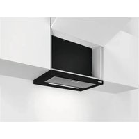
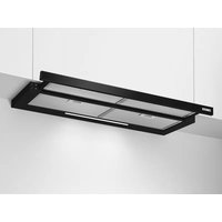
This cookeenthood iss selittablefofor recirculation or extraction anditisis convertible to either function by the movement of a lever.
How to use
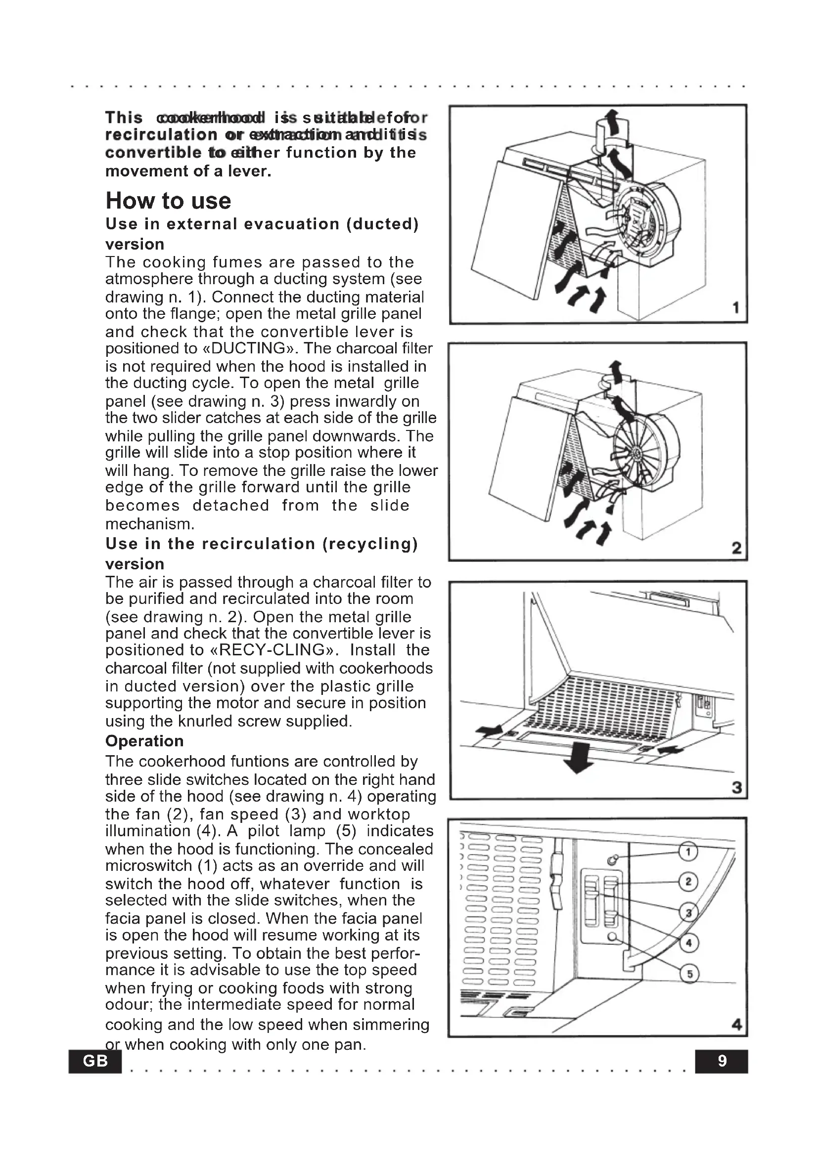
Use in external evacuation (ducted) version
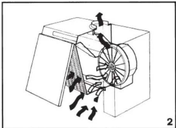
The cooking fumes are passed to the atmosphere through a ducting system (see drawing n. 1). Connect the ducting material onto the flange; open the metal grille panel and check that the convertible lever is positioned to «DUCTING». The charcoal filter is not required when the hood is installed in the ducting cycle. To open the metal grille panel (see drawing n. 3) press inwardly on the two slider catches at each side of the grille while pulling the grille panel downwards. The grille will slide into a stop position where it will hang. To remove the grille raise the lower edge of the grille forward until the grille becomes detached from the slide mechanism.
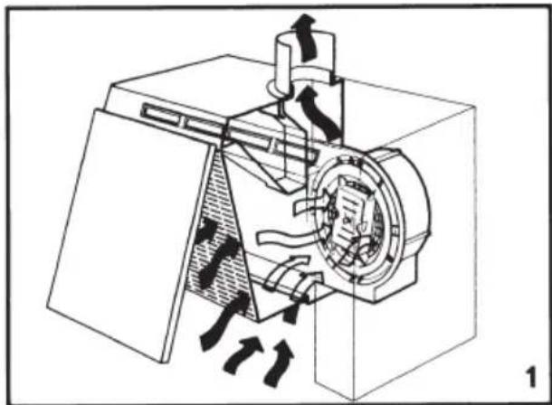
Use in the recirculation (recycling) version
The air is passed through a charcoal filter to be purified and recirculated into the room (see drawing n. 2). Open the metal grille panel and check that the convertible lever is positioned to «RECY-CLING». Install the charcoal filter (not supplied with cookerhoods in ducted version) over the plastic grille supporting the motor and secure in position using the knurled screw supplied.
Operation
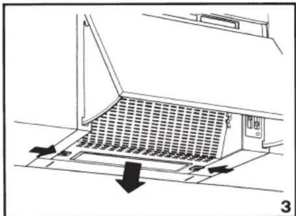
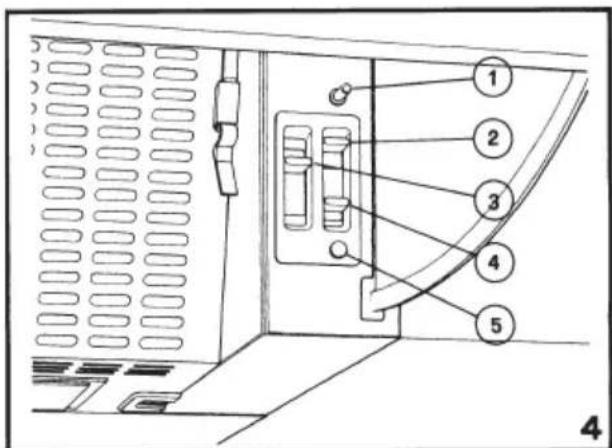
The cookerhood funtions are controlled by three slide switches located on the right hand side of the hood (see drawing n. 4) operating the fan (2), fan speed (3) and worktop illumination (4). A pilot lamp (5) indicates when the hood is functioning. The concealed microswitch (1) acts as an override and will switch the hood off, whatever function is selected with the slide switches, when the facia panel is closed. When the facia panel is open the hood will resume working at its previous setting. To obtain the best performance it is advisable to use the top speed when frying or cooking foods with strong odour; the intermediate speed for normal cooking and the low speed when simmering or when cooking with only one pan.
Maintenance and cleaning
Regular maintenance and cleaning ensure good reliability, performance and extended working life. Special attention should be taken to keep the grease filter clean at all times. The grease filter retains the solid grease particles. It is fitted onto the reverse side of the lower grille panel and can be supplied in different materials. Maintenance of the grease filter varies according to the type of material used.
Synthetic fibre grease filter
(8/10 mm thick)
It should be washed once a month in hot water and mild detergent and should be squeezed dry, not wrung out. It should be replaced every six months.
Synthetic grease filter
(1 mm thick) (thin filter)
This filter cannot be washed nor regenerated and should be replaced every three months.
Combined grease filter
(thin synthetic filter and metal filter)
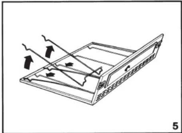
The synthetic filter cannot be washed nor regenerated and should be replaced every three months. The metal filter should be washed once a month in hot water and mild detergent and left to drain dry. It should not be bent. It is recommended to ensure effective operation of the product that the grease filters are cleaned and replaced as directed. Care must be taken to avoid a heavy accumulation of grease as it could be a possible fire hazard. To remove the grease filter first remove the grille and then remove the filter from the grille by pushing the spring wire clips to one side (see drawing n. 5).
Charcoal filter
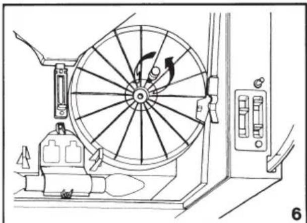
It is used only when the cookerhood is in the recycling mode. The charcoal filter absorbs smells and odours when the air passes through it. It cannot be cleaned and should be replaced every three months. To replace the charcoal filter, open the grille panel and unscrew the knurled screw in the centre of the charcoal filter (see drawing n. 6).
Worktop illumination
To replace the light bulbs open the grille panel and change the lamp using an identical replacement to ensure a safe working of the hood.
IMPORTANT
The electric plant is provided with earthing in compliance with international safety regulations. For safety, when installed the hood must be positioned at least 65~cm above the hotplate. Never leave frying pans unattended during use as overheated fats and oils may catch fire. Never do flambe cooking under a hood. The cookerhood ducting must never be connected to central heating flues, radiators or water heaters, etc.
Before connection to the mainissupply ensure that the mains voltage corresponds to the voltage on the rating plate inside the hood. Before carrying out any kind of maintenance or cleaning, disconnect the hood from the mains supply.
Fitting the decor panel
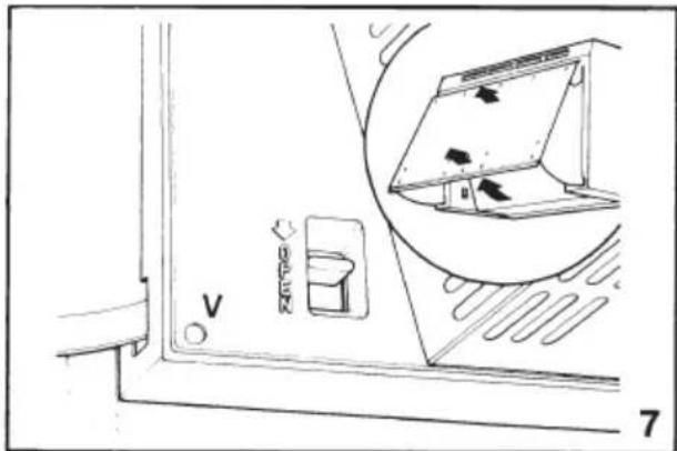
To fit the decor panel onto the hood will require the removal of the complete facia panel from the hood. Pull the panel out into the operating position, press down on the release catch located behind the door on the left side of the casing to allow the facia panel to be removed. The decor panel should be fitted in accordance with the template instructions using the 8 n. 3,9 × 13 ~mm dia. screws supplied. Replace the facia panel ensuring that it is seated correctly into the two side guides. Act on the two V screws placed inside the heads dor adjusting the vapor shield sliding (see drawing n. 7).
Fixing side panels
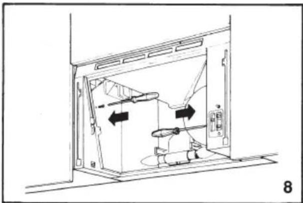
To fit to the wooden side panels drill the side panels in accordance with the template instructions supplied. Remove the facia panel and grille. Secure the hood to the side panels with the 8 n. 3,5 × 16 ~mm dia. screws supplied, through the holes in the sides of the casing into the holes pre-drilled in the wooden side panels (see drawing n. 8).
Wall fitting
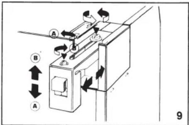
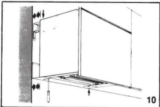
Use the paper template provided to mark the hole position on the wall for the bracket fixing screws. Two brackets and four screws with rawl plugs are supplied. The brackets should be fixed with the round end to the bottom. Access to the wall levelling screws is from above the hood. These are located in two extension arms at either side of the hood which fit over the wall brackets to support the hood. By loosening the screws at the front of each extension arm the hood can be aligned at the correct distance from the wall with the front of the adjoining wall cabinets. By rotating the screw at the rear of each extension arm clockwise the hood can be lowered. Adjustment in an anti-clockwise direction raises the hood, to ensure perfect alignment with wall cabinets (see drawing n. 9-10).
Dunne antivetfilter in
kunstvezel
(dikte 1 mm)
The symbol on the product or on its packaging indicates that this product may not be treated as household waste. Instead it shall be handed over to the applicable collection point for the recycling of electrical and electronic equipment. By ensuring this product is disposed of correctly, you will help prevent potential negative consequences for the environment and human health, which could otherwise be caused by inappropriate waste handling of this product. For more detailed information about recycling of this product, please contact your local city office, your household waste disposal service or the shop where you purchased the product.