
DSL801ZU - Sander MAKITA - Free user manual and instructions
Find the device manual for free DSL801ZU MAKITA in PDF.
| Product type | Cordless wall sander |
| Brand | Makita |
| Model | DSL801ZU |
| Dimensions (L x W x H) | 1,120 - 1,540 mm x 278 mm x 273 mm (variable length with telescopic tube) |
| Net weight | 4.6 - 5.8 kg (depending on battery and accessories) |
| Power supply | Lithium-ion battery 18 V DC (compatible models: BL1815N, BL1820B, BL1830B, BL1840B, BL1850B, BL1860B) |
| No load speed | 1,000 - 1,800 min⁻¹ (adjustable in 5 steps) |
| Pad diameter | 210 mm |
| Abrasive paper size | 225 mm |
| Sound pressure level | 78 dB(A) (uncertainty K=3 dB) |
| Vibration (sanding) | ≤ 2.5 m/s² (uncertainty K=1.5 m/s²) |
| Main functions | Variable speed, soft start, electronic speed control, wireless activation function (with optional connector) |
| Vacuum cleaner connection | Yes, via front sleeve 24 (compatible Makita vacuum cleaner) |
| Telescopic handle | Optional (with belt and support for overhead work) |
| Battery type | Lithium-ion 18 V (use only genuine Makita batteries) |
| Compatible charger | DC18RC, DC18RD, DC18RE, DC18SD, DC18SE, DC18SF, DC18SH |
| Safety | Trigger lock, protection against overload, overheating and deep discharge, battery protection system |
| Maintenance | Clean with a soft dry cloth; lubrication not required; have repairs done by a Makita authorized service center |
| Spare parts | Abrasive discs, pads, telescopic handle, wireless connector, genuine Makita batteries and chargers |
| Warranty | Manufacturer warranty applicable according to country (use only Makita accessories) |
| Intended use | Sanding of plasterboard or ceilings |
Frequently Asked Questions - DSL801ZU MAKITA
User questions about DSL801ZU MAKITA
0 question about this device. Answer the ones you know or ask your own.
Ask a new question about this device
Download the instructions for your Sander in PDF format for free! Find your manual DSL801ZU - MAKITA and take your electronic device back in hand. On this page are published all the documents necessary for the use of your device. DSL801ZU by MAKITA.
USER MANUAL DSL801ZU MAKITA
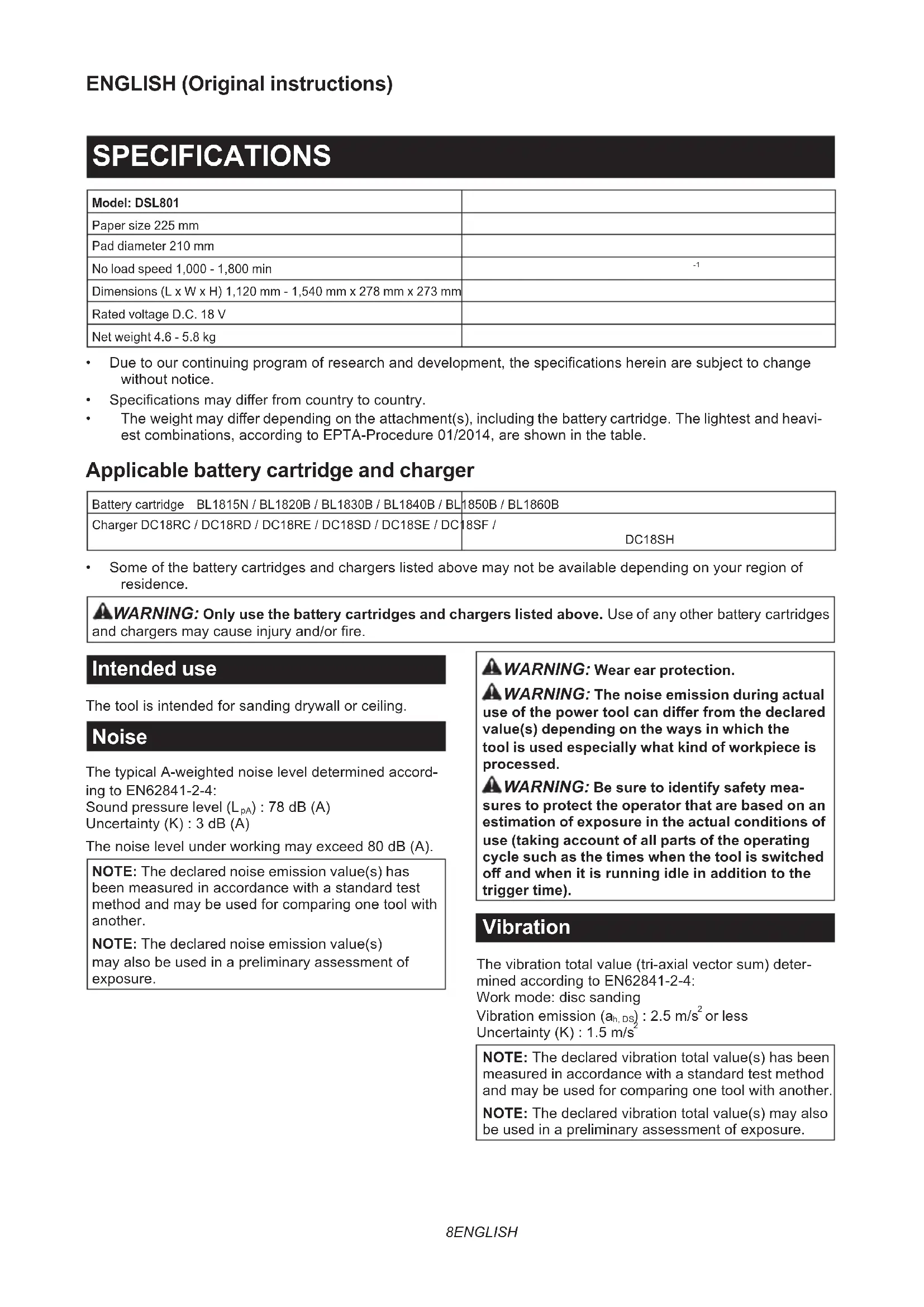
- Due to our continuing program of research and development, the specifications herein are subject to change without notice.
Specifications may differ from country to country.
The weight may differ depending on the attachment(s), including the battery cartridge. The lightest and heaviest combinations, according to EPTA-Procedure 01/2014, are shown in the table.
Applicable battery cartridge and charger
| Battery cartridge BL1815N / BL1820B / BL1830B / BL1840B / BL | 1850B / BL1860B |
| Charger DC18RC / DC18RD / DC18RE / DC18SD / DC18SE / DC18SF / DC18SH | |
Some of the battery cartridges and chargers listed above may not be available depending on your region of residence.
WARNING: Only use the battery cartridges and chargers listed above. Use of any other battery cartridges and chargers may cause injury and/or fire.
Intended use
The tool is intended for sanding drywall or ceiling.
Noise
The typical A-weighted noise level determined according to EN62841-2-4:
Sound pressure level (L_pA):78 dB (A)
Uncertainty (K):3 dB (A)
The noise level under working may exceed 80 dB (A).
NOTE: The declared noise emission value(s) has been measured in accordance with a standard test method and may be used for comparing one tool with another.
NOTE: The declared noise emission value(s) may also be used in a preliminary assessment of exposure.
WARNING: Wear ear protection.
WARNING: The noise emission during actual use of the power tool can differ from the declared value(s) depending on the ways in which the tool is used especially what kind of workpiece is processed.
WARNING: Be sure to identify safety measures to protect the operator that are based on an estimation of exposure in the actual conditions of use (taking account of all parts of the operating cycle such as the times when the tool is switched off and when it is running idle in addition to the trigger time).
Vibration
The vibration total value (tri-axial vector sum) determined according to EN62841-2-4:
Work mode: disc sanding
Vibration emission (a_h,DS): 2.5m/s^2 or less
Uncertainty (K): 1.5m/s^2
NOTE: The declared vibration total value(s) has been measured in accordance with a standard test method and may be used for comparing one tool with another. NOTE: The declared vibration total value(s) may also be used in a preliminary assessment of exposure.
WARNING: The vibration emission during actual use of the power tool can differ from the declared value(s) depending on the ways in which the tool is used especially what kind of workpiece is processed.
WARNING: Be sure to identify safety measures to protect the operator that are based on an estimation of exposure in the actual conditions of use (taking account of all parts of the operating cycle such as the times when the tool is switched off and when it is running idle in addition to the trigger time).
Declarations of Conformity
For European countries only
The Declarations of conformity are included in Annex A to this instruction manual.
SAFETYWARNINGS
General power tool safety warnings
WARNING Read all safety warnings, instructions, illustrations and specifications provided with this power tool. Failure to follow all instructions listed below may result in electric shock, fire and/or serious injury.
Save all warnings and instructions for future reference.
The term "power tool" in the warnings refers to your mains-operated (corded) power tool or battery-operated (cordless) power tool.
Cordless drywall sander safety warnings
SafetyWarnings Common for Sanding Operations:
- This power tool is intended to function as a sander. Read all safety warnings, instructions, illustrations and specifications provided with this power tool. Failure to follow all instructions listed below may result in electric shock, fire and/or serious injury.
- Operations such as grinding, wire brushing, polishing or cutting-off are not recommended to be performed with this power tool. Operations for which the power tool was not designed may create a hazard and cause personal injury.
- Do not use accessories which are not specifically designed and recommended by the tool manufacturer. Just because the accessory can be attached to your power tool, it does not assure safe operation.
- The rated speed of the accessory must be at least equal to the maximum speed marked on the power tool. Accessories running faster than their rated speed can break and fly apart.
- The outside diameter and the thickness of your
accessory must be within the capacity rating of your power tool. Incorrectly sized accessories cannot be adequately guarded or controlled.
- Do not use a damaged accessory. Before each use inspect the accessory such as pad for cracks, tear or excess wear. If power tool or accessory is dropped, inspect for damage or install an undamaged accessory. After inspecting and installing an accessory, position yourself and bystanders away from the plane of the rotating accessory and run the power tool at maximum no-load speed for one minute. Damaged accessories will normally break apart during this test time.
- Wear personal protective equipment. Depending on application, use face shield, safety goggles or safety glasses. As appropriate, wear dust mask, hearing protectors, gloves and workshop apron capable of stopping small abrasive or workpiece fragments. The eye protection must be capable of stopping flying debris generated by various operations. The dust mask or respirator must be capable of filtrating particles generated by your operation. Prolonged exposure to high intensity noise may cause hearing loss.
- Keep bystanders a safe distance away from work area. Anyone entering the work area must wear personal protective equipment. Fragments of workpiece or of a broken accessory may fly away and cause injury beyond immediate area of operation.
- Hold the power tool by insulated gripping surfaces only, when performing an operation where the cutting tool may contact hidden wiring. Contact with a "live" wire will also make exposed metal parts of the power tool "live" and could give the operator an electric shock.
- Position the cord clear of the spinning accessory. If you lose control, the cord may be cut or snagged and your hand or arm may be pulled into the spinning accessory.
- Never lay the power tool down until the accessory has come to a complete stop. The spinning accessory may grab the surface and pull the power tool out of your control.
- Do not run the power tool while carrying it at your side. Accidental contact with the spinning accessory could snag your clothing, pulling the accessory into your body.
- Do not operate the power tool near flammable materials. Sparks could ignite these materials.
- Do not use accessories that require liquid coolants. Using water or other liquid coolants may result in electrocution or shock.
Kickback and RelatedWarnings
Kickback is a sudden reaction to a pinched or snagged rotating pad or any other accessory. Pinching or snagging causes rapid stalling of the rotating accessory which in turn causes the uncontrolled power tool to be forced in the direction opposite of the accessory's rotation at the point of the binding.
For example, if a pad is snagged or pinched by the workpiece, the edge of the pad that is entering into the pinch point can dig into the surface of the material
causing the pad to climb out or kick out. The pad may either jump toward or away from the operator, depending on direction of the pad's movement at the point of pinching. Pad may also break under these conditions. Kickback is the result of power tool misuse and/or incorrect operating procedures or conditions and can be avoided by taking proper precautions as given below.
- Maintain a firm grip on the power tool and position your body and arm to allow you to resist kickback forces. Always use auxiliary handle, if provided, for maximum control over kickback or torque reaction during start-up. The operator can control torque reactions or kickback forces, if proper precautions are taken.
- Never place your hand near the rotating accessory. Accessory may kickback over your hand.
- Do not position your body in the area where power tool will move if kickback occurs. Kickback will propel the tool in direction opposite to the wheel's movement at the point of snagging.
- Use special care when working corners, sharp edges etc. Avoid bouncing and snagging the accessory. Corners, sharp edges or bouncing have a tendency to snag the rotating accessory and cause loss of control or kickback.
- Do not attach a saw chain woodcarving blade or toothed saw blade. Such blades create frequent kickback and loss of control.
SafetyWarnings Specific for Sanding Operations:
- Do not use excessively oversized sanding disc paper. Follow manufacturers recommendations, when selecting sanding paper. Larger sanding paper extending beyond the sanding pad presents a laceration hazard and may cause snagging, tearing of the disc or kickback.
Additional SafetyWarnings:
- Do not leave the tool running. Operate the tool only when hand-held.
- Check that the workpiece is properly supported.
- Pay attention that the pad continues to rotate after the tool is switched off.
- If working place is extremely hot and humid, or badly polluted by conductive dust, use a short-circuit breaker (30 mA) to assure operator safety.
- Do not use the tool on any materials containing asbestos.
- Do not use cloth work gloves during operation. Fibers from cloth gloves may enter the tool, which causes tool breakage.
- Always work in well ventilated area.
- When placing the tool, place it on a flat and stable surface.
- When operating the tool, connect the tool to a vacuum cleaner as much as possible to keep the working area clean and prevent the operator from inhaling particles generated by the operation.
- Handle and store accessories with care.
SAVE THESE INSTRUCTIONS.
WARNING: DO NOT let comfort or familiarity with product (gained from repeated use) replace strict adherence to safety rules for the subject product. MISUSE or failure to follow the safety rules stated in this instruction manual may cause serious personal injury.
Important safety instructions for battery cartridge
- Before using battery cartridge, read all instructions and cautionary markings on (1) battery charger, (2) battery, and (3) product using battery.
- Do not disassemble or tamper with the battery cartridge. It may result in a fire, excessive heat, or explosion.
- If operating time has become excessively shorter, stop operating immediately. It may result in a risk of overheating, possible burns and even an explosion.
- If electrolyte gets into your eyes, rinse them out with clear water and seek medical attention right away. It may result in loss of your eyesight.
- Do not short the battery cartridge:
(1) Do not touch the terminals with any conductive material.
(2) Avoid storing battery cartridge in a container with other metal objects such as nails, coins, etc.
(3) Do not expose battery cartridge to water or rain.
A battery short can cause a large current flow, overheating, possible burns and even a breakdown.
- Do not store and use the tool and battery cartridge in locations where the temperature may reach or exceed 50^ (122^) .
- Do not incinerate the battery cartridge even if it is severely damaged or is completely worn out. The battery cartridge can explode in a fire.
- Do not nail, cut, crush, throw, drop the battery cartridge, or hit against a hard object to the battery cartridge. Such conduct may result in a fire, excessive heat, or explosion.
9. Do not use a damaged battery.
- The contained lithium-ion batteries are subject to the Dangerous Goods Legislation requirements.
For commercial transports e.g. by third parties, forwarding agents, special requirement on packaging and labeling must be observed.
For preparation of the item being shipped, consulting an expert for hazardous material is required.
Please also observe possibly more detailed national regulations.
Tape or mask off open contacts and pack up the battery in such a manner that it cannot move around in the packaging. -
When disposing the battery cartridge, remove it from the tool and dispose of it in a safe place. Follow your local regulations relating to disposal of battery.
-
Use the batteries only with the products specified by Makita. Installing the batteries to non-compliant products may result in a fire, excessive heat, explosion, or leak of electrolyte.
- If the tool is not used for a long period of time, the battery must be removed from the tool.
- During and after use, the battery cartridge may take on heat which can cause burns or low temperature burns. Pay attention to the handling of hot battery cartridges.
- Do not touch the terminal of the tool immediately after use as it may get hot enough to cause burns.
- Do not allow chips, dust, or soil stuck into the terminals, holes, and grooves of the battery cartridge. It may cause heating, catching fire, burst and malfunction of the tool or battery cartridge, resulting in burns or personal injury.
- Unless the tool supports the use near high-voltage electrical power lines, do not use the battery cartridge near high-voltage electrical power lines. It may result in a malfunction or breakdown of the tool or battery cartridge.
- Keep the battery away from children. SAVE THESE INSTRUCTIONS.
CAUTION: Only use genuine Makita batteries. Use of non-genuine Makita batteries, or batteries that have been altered, may result in the battery bursting causing fires, personal injury and damage. It will also void the Makita warranty for the Makita tool and charger.
Tips for maintaining maximum battery life
- Charge the battery cartridge before completely discharged. Always stop tool operation and charge the battery cartridge when you notice less tool power.
- Never recharge a fully charged battery cartridge. Overcharging shortens the battery service life.
- Charge the battery cartridge with room temperature at 10^ - 40^ (50°F - 104°F). Let a hot battery cartridge cool down before charging it.
- When not using the battery cartridge, remove it from the tool or the charger.
- Charge the battery cartridge if you do not use it for a long period (more than six months).
Important safety instructions for wireless unit
- Do not disassemble or tamper with the wireless unit.
- Keep the wireless unit away from young children. If accidentally swallowed, seek medical attention immediately.
- Use the wireless unit only with Makita tools.
- Do not expose the wireless unit to rain or wet conditions.
- Do not use the wireless unit in places where
the temperature exceeds 50^ (122°F).
6. Do not operate the wireless unit in places where medical instruments, such as heart pace makers are nearby.
7. Do not operate the wireless unit in places where automated devices are nearby. If operated, automated devices may develop malfunction or error.
8. Do not operate the wireless unit in places under high temperature or places where static electricity or electrical noise could be generated.
9. The wireless unit can produce electromagnetic fields (EMF) but they are not harmful to the user.
10. The wireless unit is an accurate instrument. Be careful not to drop or strike the wireless unit.
11. Avoid touching the terminal of the wireless unit with bare hands or metallic materials.
12. Always remove the battery on the product when installing the wireless unit into it.
13. When opening the lid of the slot, avoid the place where dust and water may come into the slot. Always keep the inlet of the slot clean.
14. Always insert the wireless unit in the correct direction.
15. Do not press the wireless activation button on the wireless unit too hard and/or press the button with an object with a sharp edge.
16. Always close the lid of the slot when operating.
17. Do not remove the wireless unit from the slot while the power is being supplied to the tool. Doing so may cause a malfunction of the wireless unit.
18. Do not remove the sticker on the wireless unit.
19. Do not put any sticker on the wireless unit.
20. Do not leave the wireless unit in a place where static electricity or electrical noise could be generated.
21. Do not leave the wireless unit in a place subject to high heat, such as a car sitting in the sun.
22. Do not leave the wireless unit in a dusty or powdery place or in a place corrosive gas could be generated.
23. Sudden change of the temperature may bedew the wireless unit. Do not use the wireless unit until the dew is completely dried.
24. When cleaning the wireless unit, gently wipe with a dry soft cloth. Do not use benzine, thinner, conductive grease or the like.
25. When storing the wireless unit, keep it in the supplied case or a static-free container.
26. Do not insert any devices other than Makita wireless unit into the slot on the tool.
27. Do not use the tool with the lid of the slot damaged. Water, dust, and dirt come into the slot may cause malfunction.
28. Do not pull and/or twist the lid of the slot more than necessary. Restore the lid if it comes off from the tool.
29. Replace the lid of the slot if it is lost or
damaged. SAVE THESE INSTRUCTIONS.
FUNCTIONAL DESCRIPTION
CAUTION: Always be sure that the tool is switched off and the battery cartridge is removed before adjusting or checking function on the tool.
Installing or removing battery cartridge
CAUTION: Always switch off the tool before installing or removing of the battery cartridge.
CAUTION: Hold the tool and the battery cartridge firmly when installing or removing battery cartridge. Failure to hold the tool and the battery cartridge firmly may cause them to slip off your hands and result in damage to the tool and battery cartridge and a personal injury.
Fig.1: 1. Red indicator 2. Button 3. Battery cartridge
To remove the battery cartridge, slide it from the tool while sliding the button on the front of the cartridge.
To install the battery cartridge, align the tongue on the battery cartridge with the groove in the housing and slip it into place. Insert it all the way until it locks in place with a little click. If you can see the red indicator as shown in the figure, it is not locked completely.
CAUTION: Always install the battery cartridge fully until the red indicator cannot be seen. If not, it may accidentally fall out of the tool, causing injury to you or someone around you.
CAUTION: Do not install the battery cartridge forcibly. If the cartridge does not slide in easily, it is not being inserted correctly.
Indicating the remaining battery capacity
Only for battery cartridges with the indicator
Press the check button on the battery cartridge to indicate the remaining battery capacity. The indicator lamps light up for a few seconds.
Fig.2: 1. Indicator lamps 2. Check button
| Indicator lamps Remaining | capacity | ||
| Lighted Off | Blinking | ||
| 75% to 100% | |||
| 50% to 75% | |||
| 25% to 50% | |||
| Indicator lamps Remaining | capacity | ||
| Lighted Off | Blinking | ||
| 0% to 25% | |||
| Charge the battery. | |||
| The battery may have malfunctioned. | |||
NOTE: Depending on the conditions of use and the ambient temperature, the indication may differ slightly from the actual capacity.
NOTE: The first (far left) indicator lamp will blink when the battery protection system works.
Tool / battery protection system
The tool is equipped with a tool/battery protection system. This system automatically cuts off power to the motor to extend tool and battery life. The tool will automatically stop during operation if the tool or battery is placed under one of the following conditions:
Overload protection
When the tool or battery is operated in a manner that causes it to draw an abnormally high current, the tool automatically stops and the lamp blinks. In this situation, turn the tool off and stop the application that caused the tool to become overloaded. Then turn the tool on to restart.
Overheat protection
When the tool or battery is overheated, the tool stops automatically and the lamp lights up. In this case, let the tool and battery cool before turning the tool on again.
Overdischarge protection
When the battery capacity is not enough, the tool stops automatically. In this case, remove the battery from the tool and charge the battery.
Switch action
CAUTION: Before installing the battery cartridge into the tool, always check to see that the switch trigger actuates properly and returns to the "OFF" position when released.
CAUTION: Switch can be locked in "ON" position for ease of operator comfort during extended use. Apply caution when locking tool in "ON" position and maintain firm grasp on tool.
CAUTION: Do not install the battery cartridge with the lock button engaged.
CAUTION: When not operating the tool, depress the trigger-lock button from inside to lock the switch trigger in the OFF position.
Fig.3: 1. Trigger-lock button
Fig.4: 1. Switch trigger 2. Lock button 3. Trigger-lock button
To prevent the switch trigger from accidentally pulled, the trigger-lock button is provided. To start the tool, depress the trigger-lock button from A (B) side and pull the switch trigger. Release the switch trigger to stop. After use, depress the trigger-lock button from B (B) side.
For continuous operation, depress the lock button while pulling the switch trigger, and then release the switch trigger. To stop the tool, pull the switch trigger fully, then release it.
Speed adjusting dial
Fig.5: 1. Speed adjusting dial
The rotation speed of the tool can be changed by turning the speed adjusting dial. The table below shows the number on the dial and the corresponding rotation speed.
| Number Speed | |
| 1 1,000 min | -1 |
| 2 1,200 min | -1 |
| 3 1,400 min | -1 |
| 4 1,600 min | -1 |
| 5 1,800 min | -1 |
NOTICE: The speed adjusting dial can be turned only as far as 5 and back to 1. Do not force it past 5 or 1, or the speed adjusting function may no longer work.
Overload and overheat indicator lamp
Fig.6: 1. Indicator lamp
If the tool is operated with excessive load, the tool stops automatically and the indicator lamp blinks in red. In this case, reduce the load on the tool.
If the tool is overheated, the tool stops automatically and the indicator lamp lights up in red. In this case, let the tool cool down before turning the tool on again.
Electronic function
The tools equipped with electronic function are easy to operate because of the following features.
Constant speed control
Possible to get fine finish, because the rotating speed is kept constant even under the loaded condition.
Soft start feature
Soft start because of suppressed starting shock.
ASSEMBLY
CAUTION: Always be sure that the tool is switched off and the battery cartridge is removed before carrying out any work on the tool.
Installing the abrasive disc
Fig.7: 1. Abrasive disc 2. Pad
Remove any dirt or foreign matter from the pad, and then attach the abrasive disc to the pad while aligning the holes in the abrasive disc with those in the pad.
Adjusting the pipe length
CAUTION: When adjusting the pipe length, hold the tool horizontally. Otherwise, the pipe length may change unintentionally and it may cause an injury or malfunction of the tool.
NOTICE: Do not extend the pipe beyond the limit. Failure to do so may cause a malfunction of the tool.
Fig.8: 1. Sleeve 2. Pipe
To adjust the pipe length, loosen the sleeve, then adjust the length of the pipe, and then tighten the sleeve.
Hex wrench storage
Fig.9: 1. Hex wrench
When not in use, store the hex wrench as shown in the figure to keep it from being lost.
Installing or removing the pad
Fig.10: 1. Hex wrench 2. Bolt 3. Pad
To remove the pad, remove the abrasive disc from the pad, and then turn the bolt counterclockwise with a hex wrench. To install the pad, perform the removal procedure in reverse.
CAUTION: Make sure that the pad is secured properly. Loose attachment will run out of balance and cause an excessive vibration which may cause loss of control.
Connecting a vacuum cleaner
Optional accessory
When you wish to perform operation cleanly, connect a Makita vacuum cleaner to your tool. Connect a hose of the vacuum cleaner to the dust nozzle using the front cuff 24.
▶ Fig.11: 1. Hose of the vacuum cleaner 2. Front cuff 24 3. Dust nozzle
Installing or removing the extension handle
Optional accessory
To install the extension handle, attach the extension handle to the tool and secure it with the knob firmly. Be
sure to insert the end of the tool into the holder of the extension handle. To remove the extension handle, perform the installation procedure in reverse.
Fig.12: 1. Extension handle 2. Knob 3. Holder 4. End of tool 5. Mounting hole
WARNING: Use the mounting hole of the tool only for attaching the extension handle.
Using the mounting hole for any other purpose may cause an unexpected accident.
OPERATION
CAUTION: Only use Makita genuine pads for sanding (optional accessories).
CAUTION: Make sure the work material is secured and stable. Falling object may cause personal injury.
CAUTION: Hold the tool firmly with one hand on the switch handle and the other hand on the front grip when operating the tool.
CAUTION: Do not run the tool at high load over an extended time period. It may result in tool malfunction which causes electric shock, fire and/or serious injury.
CAUTION: Be careful not to touch the rotating part.
NOTICE: Never force the tool. Excessive pressure may lead to decreased sanding efficiency, damaged pad, or shorten tool life.
NOTICE: Continuous operation at high speed may damage work surface.
- Position the tool lightly against the work surface. Apply light pressure enough to align the sanding head with the work surface.
- Apply additional pressure to engage the pad on the work surface. Move the tool in an overlapping pattern in constant motion to smooth the drywall compound.
Fig.13
Operating the tool with the extension handle
Optional accessory
CAUTION: Hold the tool firmly with one hand on the switch handle and the other hand on the extension handle when operating the tool with the extension handle.
CAUTION: Take extra care for the footing and balance when handling the tool with the extension handle.
- Wear the belt for the extension handle as shown in the figure.
Fig.14: 1.Belt
- Attach the holder to the belt.
Fig.15: 1.Holder 2.Belt - Put the end of the extension handle into the holder to support the tool.
Fig.16: 1. End of extension handle 2. Holder
Operate the tool in the same way as the tool without the extension handle.
Operate the tool in the same way as the tool without the extension handle.
You can also operate the tool without using the belt and the holder as shown in the figure.
Fig.17
Fig.18
WIRELESS ACTIVATION FUNCTION
Optional accessory
What you can do with the wireless activation function
The wireless activation function enables clean and comfortable operation. By connecting a supported vacuum cleaner to the tool, you can run the vacuum cleaner automatically along with the switch operation of the tool.
Fig.19
To use the wireless activation function, prepare following items:
- A wireless unit (optional accessory)
A vacuum cleaner which supports the wireless activation function
The overview of the wireless activation function setting is as follows. Refer to each section for detail procedures.
- Installing the wireless unit
- Tool registration for the vacuum cleaner
- Starting the wireless activation function
Installing the wireless unit
Optional accessory
CAUTION: Place the tool on a flat and stable surface when installing the wireless unit.
NOTICE: Clean the dust and dirt on the tool before installing the wireless unit. Dust or dirt may cause malfunction if it comes into the slot of the wireless unit.
NOTICE: To prevent the malfunction caused by static, touch a static discharging material, such as a metal part of the tool, before picking up the wireless unit.
NOTICE: When installing the wireless unit, always be sure that the wireless unit is inserted in the correct direction and the lid is completely closed.
- Open the lid on the tool as shown in the figure.
Fig.20: 1. Lid
- Insert the wireless unit to the slot and then close the lid.
When inserting the wireless unit, align the projections with the recessed portions on the slot.
Fig.21: 1. Wireless unit 2. Projection 3. Lid
-
Recessed portion
-
When removing the wireless unit, open the lid slowly.
- The hooks on the back of the lid will lift the wireless unit as you pull up the lid.
Fig.22: 1. Wireless unit 2. Hook 3. Lid
After removing the wireless unit, keep it in the supplied case or a static-free container.
NOTICE: Always use the hooks on the back of the lid when removing the wireless unit. If the hooks do not catch the wireless unit, close the lid completely and open it slowly again.
Tool registration for the vacuum cleaner
NOTE: A Makita vacuum cleaner supporting the wireless activation function is required for the tool registration.
NOTE: Finish installing the wireless unit to the tool before starting the tool registration.
NOTE: During the tool registration, do not pull the switch trigger or turn on the power switch on the vacuum cleaner.
NOTE: Refer to the instruction manual of the vacuum cleaner, too.
If you wish to activate the vacuum cleaner along with the switch operation of the tool, finish the tool registration beforehand.
- Install the batteries to the vacuum cleaner and the tool.
- Set the stand-by switch on the vacuum cleaner to "AUTO".
Fig.23: 1. Stand-by switch
3. Press the wireless activation button on the vacuum cleaner for 3 seconds until the wireless activation lamp blinks in green. And then press the wireless activation button on the tool in the same way.
Fig.24: 1. Wireless activation button 2. Wireless activation lamp
If the vacuum cleaner and the tool are linked successfully, the wireless activation lamps will light up in green for 2 seconds and start blinking in blue.
NOTE: The wireless activation lamps finish blinking in green after 20 seconds elapsed. Press the wireless activation button on the tool while the wireless activation lamp on the cleaner is blinking. If the wireless activation lamp does not blink in green, push the wireless activation button briefly and hold it down again.
NOTE: When performing two or more tool registrations for one vacuum cleaner, finish the tool registration one by one.
Starting the wireless activation function
NOTE: Finish the tool registration for the vacuum cleaner prior to the wireless activation.
NOTE: Refer to the instruction manual of the vacuum cleaner, too.
After registering a tool to the vacuum cleaner, the vacuum cleaner will automatically run along with the switch operation of the tool.
- Install the wireless unit to the tool.
- Connect the hose of the vacuum cleaner with the tool.
Fig.25
-
Set the stand-by switch on the vacuum cleaner to "AUTO".
Fig.26: 1. Stand-by switch -
Push the wireless activation button on the tool briefly. The wireless activation lamp will blink in blue.
Fig.27: 1. Wireless activation button 2. Wireless activation lamp -
Turn on the tool. Check if the vacuum cleaner runs while the tool is operating.
To stop the wireless activation of the vacuum cleaner, push the wireless activation button on the tool.
NOTE: The wireless activation lamp on the tool will stop blinking in blue when there is no operation for 2 hours. In this case, set the stand-by switch on the vacuum cleaner to "AUTO" and push the wireless activation button on the tool again.
NOTE: The vacuum cleaner starts/stops with a delay. There is a time lag when the vacuum cleaner detects a switch operation of the tool.
NOTE: The transmission distance of the wireless unit may vary depending on the location and surrounding circumstances.
NOTE: When two or more tools are registered to one vacuum cleaner, the vacuum cleaner may start running even if you do not turn on your tool because another user is using the wireless activation function.
Description of the wireless activation lamp status
Fig.28: 1. Wireless activation lamp
The wireless activation lamp shows the status of the wireless activation function. Refer to the table below for the meaning of the lamp status.
| Status Wireless activation lamp Description | |||||
| Color | On | Blinking | Duration | ||
| Standby | Blue | # | 2 hours The wireless activation of the vacuum cleaner is available. The lamp will automatically turn off when no operation is performed for 2 hours. | ||
| # | When the tool is running. | The wireless activation of the vacuum cleaner is available and the tool is running. | |||
| Tool registration | Green | # | 20 seconds Ready for the tool registration. Waiting for the registration by the vacuum cleaner. | ||
| # | 2 seconds The tool registration has been finished. The wireless activation lamp will start blinking in blue. | ||||
| Cancelling tool registration | Red | # | 20 seconds Ready for the cancellation of the tool registration. Waiting for the cancellation by the vacuum cleaner. | ||
| # | 2 seconds The cancellation of the tool registration has been finished. The wireless activation lamp will start blinking in blue. | ||||
| Others Red | # | 3 seconds The power is supplied to the wireless unit and the wireless activation function is starting up. | |||
| - | - The wireless activation of the vacuum cleaner is stopped. | ||||
Cancelling tool registration for the vacuum cleaner
Perform the following procedure when cancelling the tool registration for the vacuum cleaner.
- Install the batteries to the vacuum cleaner and the tool.
- Set the stand-by switch on the vacuum cleaner to "AUTO".
Fig.29: 1. Stand-by switch
- Press the wireless activation button on the vacuum cleaner for 6 seconds. The wireless activation lamp blinks in green and then become red. After that,
press the wireless activation button on the tool in the same way.
Fig.30: 1. Wireless activation button 2. Wireless activation lamp
If the cancellation is performed successfully, the wireless activation lamps will light up in red for 2 seconds and start blinking in blue.
NOTE: The wireless activation lamps finish blinking in red after 20 seconds elapsed. Press the wireless activation button on the tool while the wireless activation lamp on the cleaner is blinking. If the wireless activation lamp does not blink in red, push the wireless activation button briefly and hold it down again.
Troubleshooting for wireless activation function
Before asking for repairs, conduct your own inspection first. If you find a problem that is not explained in the manual, do not attempt to dismantle the tool. Instead, ask Makita Authorized Service Centers, always using Makita replacement parts for repairs.
| State of abnormality Probable cause | (malfunction) Remedy | |
| The wireless activation lamp does not light/blink. | The wireless unit is not installed into the tool.The wireless unit is improperly installed into the tool. | Install the wireless unit correctly. |
| The terminal of the wireless unit and/or the slot is dirty. | Gently wipe off dust and dirt on the terminal of the wireless unit and clean the slot. | |
| The wireless activation button on the tool has not been pushed. | Push the wireless activation button on the tool briefly. | |
| The stand-by switch on the vacuum cleaner is not set to "AUTO". | Set the stand-by switch on the vacuum cleaner to "AUTO". | |
| No power supply | Supply the power to the tool and the vacuum cleaner. | |
| Cannot finish tool registration / can-celling tool registration successfully. | The wireless unit is not installed into the tool.The wireless unit is improperly installed into the tool. | Install the wireless unit correctly. |
| The terminal of the wireless unit and/or the slot is dirty. | Gently wipe off dust and dirt on the terminal of the wireless unit and clean the slot. | |
| The stand-by switch on the vacuum cleaner is not set to "AUTO". | Set the stand-by switch on the vacuum cleaner to "AUTO". | |
| No power supply Supply the power to the tool | the tool and the vacuum cleaner. | |
| Incorrect operation Push the wireless act | ivation button briefly and perform the tool registration/cancellation procedures again. | |
| The tool and vacuum cleaner are away from each other (out of the transmission range). | Get the tool and vacuum cleaner closer to each other. The maximum transmission distance is approximately 10 m however it may vary according to the circumstances. | |
| Before finishing the tool registration/cancellation; - the switch of the tool is turned on or; - the power button on the vacuum cleaner is turned on. | Push the wireless activation button briefly and perform the tool registration/cancellation procedures again. | |
| The tool registration procedures for the tool or vacuum cleaner have not finished. | Perform the tool registration procedures for both the tool and the vacuum cleaner at the same timing. | |
| Radio disturbance by other appliances which generate high-intensity radio waves. | Keep the tool and vacuum cleaner away from the appliances such as Wi-Fi devices and microwave ovens. | |
| The vacuum cleaner does not run along with the switch operation of the tool. | The wireless unit is not installed into the tool.The wireless unit is improperly installed into the tool. | Install the wireless unit correctly. |
| The terminal of the wireless unit and/or the slot is dirty. | Gently wipe off dust and dirt on the terminal of the wireless unit and clean the slot. | |
| The wireless activation button on the tool has not been pushed. | Push the wireless activation button briefly and make sure that the wireless activation lamp is blinking in blue. | |
| The stand-by switch on the vacuum cleaner is not set to "AUTO". | Set the stand-by switch on the vacuum cleaner to "AUTO". | |
| More than 10 tools are registered to the vacuum cleaner. | Perform the tool registration again. If more than 10 tools are registered to the vacuum cleaner, the tool registered earliest will be cancelled automatically. | |
| The vacuum cleaner erased all tool registrations. | Perform the tool registration again. | |
| No power supply Supply the power to the tool | the tool and the vacuum cleaner. | |
| The tool and vacuum cleaner are away from each other (out of the transmission range). | Get the tool and vacuum cleaner closer each other. The maximum transmission distance is approximately 10 m however it may vary according to the circumstances. | |
| Radio disturbance by other appliances which generate high-intensity radio waves. | Keep the tool and vacuum cleaner away from the appliances such as Wi-Fi devices and microwave ovens. | |
| The vacuum cleaner runs while the tool is not operating. | Other users are using the wireless activation of the vacuum cleaner with their tools. | Turn off the wireless activation button of the other tools or cancel the tool registration of the other tools. |
MAINTENANCE
CAUTION: Always be sure that the tool is switched off and the battery cartridge is removed before attempting to perform inspection or maintenance.
NOTICE: Never use gasoline, benzine, thinner, alcohol or the like. Discoloration, deformation or cracks may result.
To maintain product SAFETY and RELIABILITY, repairs, any other maintenance or adjustment should be performed by Makita Authorized or Factory Service Centers, always using Makita replacement parts.
Storing the tool in the tool bag
When storing the tool in the tool bag, fix it with the hook and loop fasteners as shown in the figure.
Fig.31: 1. Hook and loop fastener 2. Tool
When storing the tool and the extension handle in the tool bag, fix them with the hook and loop fasteners as shown in the figure.
▶ Fig.32: 1. Hook and loop fastener 2. Extension handle 3. Tool
OPTIONAL ACCESSORIES
CAUTION: These accessories or attachments are recommended for use with your Makita tool specified in this manual. The use of any other accessories or attachments might present a risk of injury to persons. Only use accessory or attachment for its stated purpose.
If you need any assistance for more details regarding these accessories, ask your local Makita Service Center.
- Abrasive disc
Pad - Extension handle (with belt and holder)
- Wireless unit
- Makita genuine battery and charger
NOTE: Some items in the list may be included in the tool package as standard accessories. They may differ from country to country.
SPÉCIFICATIONS
ACCESSIONS EN OPTION
VEILIGHEIDSWAARSCHUWINGEN
OPTIONELE ACCESSOIRES
Móvo yia xwpe ts Eupwnns
Oi Anwoeicuupoppwang Tepiaaavovtai oTo Iapaptnma A oTo npov EYxepidio odnyiwv.
IPOEIAOIOIHSEIEA ΣΦΑΛΕΙΑΣ
Evikc npoeiooioeic a0aaleiayia to nEKTpiKO epyaeeio
A PPOEI OIOIH AiaBaoTe oLe TIC TPOEI- 0toioeic aoPaeiaoc, odnyiec, EIKOVoypapnoeic KAI TPObiaypaec Tou npexovtaI e auto to nKtpikoepyaleio. H un tnpon oawv twv onyiw Tou avayapovtai katwetpw mTopei va kataanxi e nKtpoTTnGia, TUPKayia n/kai oobapo tpaumatio.
UaTe oEc TIG POeiooIn- 0EIC KAI TIG OByIc yia eAloxvTKn TapaTouTn.
Tic TpoeioToinoei, o opoc «nEeKtpko epyaaleio» avapepetai e nEeKtpko epyaaleio Tou TpoopodoteiTai aTnv Kupia npoxn nEeKtpkou pEuμatoc (e nEeKtpko kaawio) n e nEeKtpko epyaaleio Tou TpoopodoteiTai aTTOATAPIA (xwpiç nEeKtpko kaawio).
PpOeIodOnoiNoεiασφaλεiαγiaTo φoPntó λεiavtnpaγia yuψoσavida
Ppoeiobotoinoeic aopaaiaac koivcs yia epyaociec Aeiavon:
- Auto To ngektpko epyaiaio ppoopietai ia Aetoupyia wS aeavtnpac. diaaboTe oaes TIG
TPOeIOToIOEIG aOaAeaIac, OoNyieG, aTeIKOvioei KAI TPObiaypaqec TOU OuvOBeouv To TApov nAeKTPiKO epaAeo. H m npon oawv Tuv OoNiyw TOn avapaovtai Katwtepw MTopei va kataaHgE OE nAeKPTpTTnIgia, TUPkAYIa N/Kai oBapop Tpaumatio.
- ouviotatai n ekTeleon epyaiov otWc
Leiaovn, kaapiooic me oupuatoBouptoa,
Leiaovn n kottn ie auto to nektpiko epyaieio. H ekTeleon epyaoiwv ia tic oTIOe cEv exei oxE
diaotei to npov nektpiko epyaieio mtopei va
Eykuovciivouc kai va Tpokaaleoi TpOsw-
TIKO Tpaumatioo. - Mn xnpoioptoiite eapntmaata Tou evivai Eiikα oxediaoueva kai ouviotwueva attoTov kataaekuaotn Tou epyaaleiou. AIIawc kai mvo ETEHn TO eaptnu a TIOpei va TPOaaptnOeI OTo nAektpiko epyaleio, auto 8ev Egaosaaizla aqpaan λeitoupyia.
- H ovopaaotikn taxutnta tou eaptnmuoTne TTEIva Eivai ToulaXIOTOV ion ME TNV meyioTn Taxutnta Tou eivai onmeiWevn OTO nAekptiko EpyaEio.Eaptnmuata TPO AIToupyouv taxutepa aTTOv ovopaaotikn taxutnta Touc mTtpei va OTtaoovkai VA EKTOSeuOuv.
- H E\xi TEPIKn i ETPOc KAI TO 区 x区 O TOU EApTnμaTOc OAC TPEIE VA Eivai MEOA OTA OPIA IKAVOTNTAC Tou NAEKTPIKOU EPVALEIOU OAC. EapTnmuA nOwTou MVEeOUs DEV MTPoov V a TPOUAXOuv N va LEYxOouv ETAPKwS.
- Mn xnpoiopoioite Eaptnma Tou exi unootei Znui. Piv aTc Kae Xpion, va eayxete to Eaptnma, oTWC TO TEa, yia pwyec, Okiio n utepboAikn 0bpop. Se TEPITWON TTwOnc Tou nAekptikou epyaleiou n Tou eapntmuatoc, Eeyte yia tuxov kataotpoqn n totoetne Ev aEaptnma Tou dve Exei unootei Kata- stpoqn. Meta anTOv eayxo kai tvn totoTe TOn nEvoc Eapntmuatoc, kpatnthetae oeic kai oi Tapeupokoei OEon makpi aTTO ETTEO TepiotpOnc Tou eapntmuatoc kai the To nAekptikó epyaleio e aeitoupyia OTN MeyiOTn TaxUTNTa TepiTPOPns Xwpic opto, yia eva AenTo. Eapntmuatae ZnuiEc thiau- Bouv kata Tov xpov autns ts dokius
- Na φopáte atoμiKO ΕGOTLIOμo TPOOASTIaç. Avaloya μe TnV εφapuoyn, va xpnoiopoTIOIEπ TPOOWTIDa TPOOASTIaç, TPOOATEUTIKA yuaλia-TPOOWTIDc n yuaIA TPOOASTIac. Otav aTaIeITai, va φopáte maKa σKovns, TPOOATETUkαKng, YAVTIA KAI TOIa Ouvpeyeiou IKAVa v TApexouv TPOOASTIa oTo Ta EKTIVAOσóμεva μikpa θpauoMata λoyw TnS λεiavonc n Tou TEPAXIOEpyoAic. Ta TPOOATEUTIKA μatiowv TpeTIe iavai IKAVa v OTaupntoouv Tuxov kTIVAAoopeva θpaoupata Tou δnHioup-youVTai KAt Tnv EKTLEeON diapopwv Epyaivw. H μaKa OKovnc h avatveuTnpac TpeTIe va eivai IKAVn va φiltpapei σωpatidia Tapayoeva aTTO tIC λeIToupyieC oac. H Tapatetatevη ekθeON ΘθopuBo uynlnc evtaoNc μTtpei va TpokaleoI aTiwlaia akOns.
- Kpatate Touc yupw oac oe ia aopaaan ato- 0taon an tov xwpo epyaiaac. Otoiooohntote EIOepxoEvoc oTo Xwpo epyaiaac TpeTVE va opa atouiko ppoataeutiko eoTIAOuO.
Teuaxidia aTTO Teuxio epyaiaq n aTo eva
oTaoue vEaptnma uTnpoei va EKtivaxOuv
Jaepia kai va Tpokaléouv Tpaumatioo Tepav
Tns aEoans Tepioxn epyaiaq.
- Kpatate to nEeKtpio Epyaleio mOvo aTIO TIC MOwvec ETiPaveiec xeipolaaBnc otAV EKTE- Aite iA epyia kata TnV OTIO TO KOTTIKO Epyaleio mTOpei va ePtei oe tApn me Kpumu eva kaWdelta.Av yivei Etnapn me katoio nEeKtpofo po Kaawdo, ta EKTeeivvaetalikapepn Tou nEeKtpoiu Epyaleiou thayivouv kai auta nEeKtpofoopa kai mTOpei va TTPOkAnthei nEeKTPoTTAnxi oTO XePiOTn.
- KpatnoTe To kaiwio jakia aTo Tepi- stpeoEv Ogptnma.Av Xaote TOV EeYxo, To kaiwio mTopei va konei n va eunakei kai to xepi n o Bpaxiovac osu mtopeivatpaBnxtie poc to TepiotpeoEv Ogaptnma.
- Mny toTOtOtheTE TOTe TO nAektpiko Epyaaleio KATW mEXPOI TO EApTnma va Exei OTaOpatnoTeAeiwC. To pIopTpeofovo EapTnma mtopei va TiAOE iNv EtniPavEIA KA iVA TpaBnEi TO nAektpko Epyaaleio EgawtoTv Eeyxo oac.
- Mn xεipiζεοTE TO nλεκτρικό εργαλείο ενώ TO ΜεταφέρεTE ΘΟ πλεύρο σας. Tuxia επαφή με TO περιστρεφόμενο εξάρτημα μΠοείν α προκαλεόει πίασιμο στΑ ρύχα σας και ντραβήει TO εξάρτημα μέσα στΟ σωμα σας.
- Mn xeipieote To nAekpiKO epyaaio kovTa oE uphiKTA uIAka. TIVthnpEc mTopei va aVapae- Gouv Ta uIAk a auta.
- Mn xpoioiOIOIE TEgApTnMa Tou xpeia- GovTaI yukTIKA uypa. H xpno vepou n aALWv yukTIKWUyPwU pTOpeI va TTpokaAeouv NkTPOITANgia n ook.
KlotaKaOxTeKc TPOeIOToIOEIS
To kloTOnma eivai mia gapvikn avtibpaon tou epyaaleiou loyw ouoayieng n okaawmuotc Tou TEPiOTpepouevou TEaMatoC n tuxov aalou aegouap. H ouoqiyn to okaawma npokaei taxaia atwaaia eleyxou Tou TEPiOTpepoevou EApntmuTO OTIOIO uOvExia UToxpeeweI TO aveEeEyKTO nAekptkoepyaieio SE TEPiOTpOphn avtietn aTIO Ekeivn Tou eapntmuoc OTO onneio ePTLoknc.
Tia napadeiyu, eva vtaeLua unootei ouoignn okaawma oTo Teuxio epyaaic, to akpo Tou TELapatoc Tou EIOEPxetai OTo onueio uOoi nguotepie va okaei tv Ntivapaveia Tou uAikou Ppokalwvtac nV avattn- 8non n To kLOTanmu Tou TLaatao. To tlaumpe i va avattnnoeipoc to hpcos Tou xepiatn n avtieta va atouakpvtei aoTov, avaloya me tn qopa TEPiopocns Tou TElambdaatoc oTo aneio uOoiqnc. Yto autc ts ouvthke, to tlauma mtopei etiongs va unootei 0paon.
To Kaotonpa eivai aTOnTeAeAmaKaKns xpnong Tou nAektpikou epyaaleiou /kai eoaaueuvxepiauow n ouvAnkw kai mtopei va atoapeuxei ie tic katannaaes Tpopualaeseic otwosdivovtaipakatw.
- Kpatate Otaepa To nAekptiko Epyaleio kai TOTTOETnTo TO oWAsOg kAI Tov bpaxiova ETOI Wote VA AVIOATAVTAt OTIG Duvaeic Tou KLOTOnmuToG.Na XpnoImuToIEe TavTa BOn- 0ntIKn Aβn, av TApexEeTAl, vla MeyiTo BOHcO ELeVxou Tou KLOTOnmuToG n Tns potnc AvIbpaocng kata Tny Ekkivnon. O xeiPiOTnC mTOpEi va ELeVxEi Tc avTIDpaoeic potnc n Duvaeic
KloToaToC,avexouv i oI kataaanAeS TpoqulaEiC.
- Noté μη βαλεTE TO xépi σaç KOVtá σTO πεiσTpeφóμevo εξαptnμa. To εξαptnμa μπopεi va κλοτοσει σTO xépi σaç.
- Mn toToeTeNoTe To oWma OaC 0tnv Tepioxn oTou To nEeKtpiKO epyaleio a KivnOei av oumuBei KaToanma.To KIoToanma 0a 0nynoei To epyaleio 0e 0ieuovon AvtEetn Tc Kivnang Tou Tpoxou 0to 0neio EptloKnc.
- Awote iiaitepn TPOOxoh otav epyaceote OE ywies, KOATEPEc akec, kTt. Na aTOpeuyete Tnv avannoa KAI TO cKaawma Tou esaptnca ToC. wves, aixunpec akpcn h avatnohoeic exouv Tnv taon va TTPOKAoUV EITLOKn OTO TEPIOTpeo- mevo ESaptnma kai TTPOKAoUV aTTWAEiA ELeyxou n KLOTOnma.
- Mny npooapuocet e auoortpiovo, aenida SuoyauTTIKnC n Amaa Tpioviou udeltaia. Teoies ae cpiokaovu ouxvokotnka kai atwlaia eevxou.
IpoeioToinoeic aopaaiaac iikyaiaepyaoies yuaoxaptiouos:
- Mn xnpoiotoiite utepoia kyeau- Tepo eey0c biokou yuaoxaptioatoc. Akoauote tic ouotaceis tou katakeuaotn, otav emiyeve yuaoxapto. Eva yuaoxapto ueautepu yey0ousioukteivetai tepa atro ta akpa tnc baonstooptipngyuaoxaptiaqatos Eykurovi kvduvtoeupoukuiopv aipokaleoeikakawma, oxioiopo tou diokou n klotonma.
PpOeTeC TPOeIOToiOneIc a0aAeaIoc:
- Mny aqnvete To epyaiao avampevo. Xeipicote To epyaiaio mvo otav to kpatate oTo xepi.
- ELeyTe OTo TEuaxio EpyaiaC UTOOtnpietai 0Ta0epa.
- Pooose 0ti To TnAa Ouvexi eia vTepeEetai akou n kai apou TO epyaieo exei oHoei.
- Av to hépoc εpyaiaε εivai πoλ ζστο κai uypó, n utápxéi πoλ aywyiμn σκovn, xρηιμοποιnte εva ααφαλειδιακόπτη βραχuku-κλωματος (30 mA) yia va ειστε σίουροι για ασφαλή λειουργία.
- Mn xpoioTOIETo EpyaEIO e Kaveva UIKo TnU TepiExI aiaVTO.
- Mn xnpoiopoite Upaouativa yavia epya cia kata tn aeitoupyia. Oi ivc aio ta upaoua tiva yavia mtopei va eioouv oTo epyaieo, yeyovoc TPOIPOkai To nTaoIO TO epyaieou.
- Na εργαζεοτε πάντα σε καλα αεριζόμενες περioxές.
- Otav toTOnoTeTeIe To epyaIeio, va to toTOnoTeTeIe oia eniTEn kai OToaEepn Etnipaveia.
- Otav xpoiooieTo epyaleio, va ouvdeTe To epyaleioe nektpikn oouta 0o yiveTai, ia va biatnpite Tnv piox npyaoiaKaapn kai va mnu avattvei O xepiotnc ta Oomegaia Tou napayovtai ano tv npyacia.
- Na xειρίζεοτε και va ααποθηκεύετε τα εξαρήματα με προσχή.
OpaHn evapgN eTieiOn kataoTeAeTaI n aipviia evapgN.
ΣYNAPMOΛΟΓΗΞH
AnoKeuon Tou epyaaleiou otn oakou aepyaleiou
Otav aTIOthkeuEte To epyaaleio aTn oakoula epyaaleiou, OTEPEwote To ME TOUC OUVbETnpEc Bpoxou kai aykiotpou OTIWc ATIEKoviCEtaI OTNV EIKoVA.
Eik.31: 1. kai aykiotpou
2. EpyaIeio
OTAV aTTOBnKcEETo EpyaIio kai Tn IaIbTIPOeKTAoNc OTn Oakoula EpyaIeiou, OTEpeWote Ta ME Touc OuvDeTHpeC BpOxou kai aykiotpou otwC aTeIKovietai OTNV EIKOVA.
Eik.32: 1. x o u kai aykiotpou
2. Aβn πpoεκτασης 3. Epyαλείο
ΠPOAIPETIKA ΕΑPTHMATA
A PPOOXH: Auta ta agptnmuata n Tpoosaptnmuata ouviotwvrai xaon m To epyaleio Makita Tou ppiypaqntke otig odnyie autec. H xpnon otooiovhntote alwwv eapntmuatwv n Tpoasaptnmuawtovpoei va Tpokaolei kivduvo tpaumiaTIOU Oe atoqa. Na xpnoiotoiite ta eapntmuata n Tpoosaptnmuata movo via tvxponn Tou Tpoopiciovta
Eav xpeiaeote oioahtote Bontheia yia nepiooatepc
Tnpoopoeis oe oxeon me auta ta Eapntmuata, aotav-
the iTO tNIKOAC Kevtpo ESUTnPpTeNc Makita.
AeiavtikosioKoC
πελμa
AaBn TPOeKTAoNG (MEIavT KAI UTOOxEa)
Aospuat movada
Vvioia mtatapia kai qopiotns ts Makita
NAPATHPHSH: MepiKa oToiExia oTn IotaMa TnpEi va ouuTePiAubavovTai Otn ouoKeuaOia epyaEiou wC otavap EApTmuata. Mtopei va diaqepouv avaloya u xpa.
TEKNIK ÖZELLİKLER
| Model: DSL801 | |
| Kağit yüzüncü 225 mm | |
| Yastık�能 210 mm | |
| Yüksüz洋葱 1.000 - 1.800 min | -1 |
| Ebat (U x G x Y) 1.120 mm - 1.540 mm x 278 mm x 273 mm | |
| Anma voltaji D.C. 18 V | |
| Net a®,rl!, 4,6 - 5,8 kg |