
DMC-GM1LEG - Camera PANASONIC - Free user manual and instructions
Find the device manual for free DMC-GM1LEG PANASONIC in PDF.
| Product type | Digital interchangeable-lens hybrid camera |
| Brand and model | Panasonic DMC-GM1LEG (DMC-GM1 body + H-X015 lens) |
| Lens mount | Micro Four Thirds |
| Included lens | LEICA DG SUMMILUX 15 mm F1.7 ASPH. (H-X015) |
| Focal length | 15 mm (35 mm equivalent: 30 mm) |
| Maximum aperture | F1.7 |
| Minimum aperture | F16 |
| Optical construction | 9 elements in 7 groups (3 aspherical lenses, Nano coating) |
| Filter diameter | 46 mm |
| Lens dimensions | Ø 57.5 mm × 36 mm |
| Total weight (with battery and card) | Approx. 319 g |
| Power supply | Rechargeable battery (not specified, compatible with included charger) |
| Power consumption (recording) | 2.2 W |
| Power consumption (playback) | 1.5 W |
| Recordable number of photos (CIPA) | Approx. 240 photos |
| Video recording time (AVCHD FHD) | Approx. 90 minutes |
| Built-in flash | Range: 0.5 m to 9.4 m (ISO AUTO) |
| Included accessories | Lens, front/rear lens caps, decoration ring, lens hood, hood cap, body cap |
| Maintenance and cleaning | Use a soft, dry cloth. Clean the lens electrical contacts carefully. |
| Safety | Do not expose to humidity. Avoid shocks. Use only recommended accessories. |
| Spare parts and repairability | Parts available from Panasonic after-sales service. Repair by an authorized technician recommended. |
Frequently Asked Questions - DMC-GM1LEG PANASONIC
User questions about DMC-GM1LEG PANASONIC
0 question about this device. Answer the ones you know or ask your own.
Ask a new question about this device
Download the instructions for your Camera in PDF format for free! Find your manual DMC-GM1LEG - PANASONIC and take your electronic device back in hand. On this page are published all the documents necessary for the use of your device. DMC-GM1LEG by PANASONIC.
USER MANUAL DMC-GM1LEG PANASONIC
Thank you for purchasing the DMC-GM1L (Digital Camera/Lens Kit).
The lens kit contains the digital camera body (DMC-GM1) and an interchangeable lens (H-X015).
Refer to the supplied operating instructions for how to operate this unit.
Accessories
Check that all the accessories are supplied before using the camera.
Product numbers correct as of May 2014. These may be subject to change.
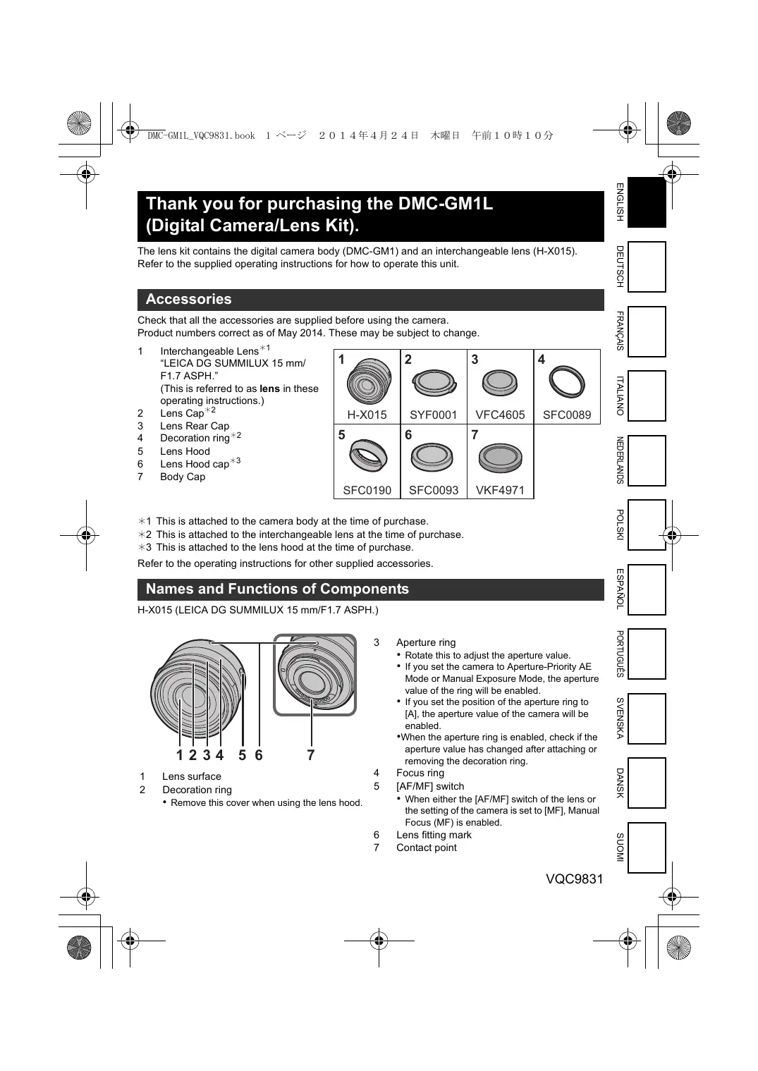
1 Interchangeable Lens ^1 "LEICA DG SUMMILUX 15 mm/
F1.7 ASPH."
(This is referred to as lens in these operating instructions.)
2 Lens Cap ^2
3 Lens Rear Cap
4 Decoration ring ^2
5 Lens Hood
6 Lens Hood cap ^3
7 Body Cap
1 H-X015 H-X015 | 2 SYF0001 SYF0001 | 3 VFC4605 VFC4605 | 4 SFC0089 SFC0089 |
5 SFC0190 SFC0190 | 6 SFC0093 SFC0093 | 7 VKF4971 VKF4971 |
*1 This is attached to the camera body at the time of purchase.
*2 This is attached to the interchangeable lens at the time of purchase.
*3 This is attached to the lens hood at the time of purchase.
Refer to the operating instructions for other supplied accessories.
Names and Functions of Components
H-X015 (LEICA DG SUMMILUX 15 mm/F1.7 ASPH.)

1 Lens surface
2 Decoration ring
- Remove this cover when using the lens hood.
3 Aperture ring
- Rotate this to adjust the aperture value.
- If you set the camera to Aperture-Priority AE Mode or Manual Exposure Mode, the aperture value of the ring will be enabled.
- If you set the position of the aperture ring to [A], the aperture value of the camera will be enabled.
- When the aperture ring is enabled, check if the aperture value has changed after attaching or removing the decoration ring.
4 Focus ring
5 [AF/MF] switch
- When either the [AF/MF] switch of the lens or the setting of the camera is set to [MF], Manual Focus (MF) is enabled.
6 Lens fitting mark
7 Contact point
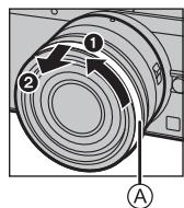
Attaching the Lens Hood
■ Interchangeable Lens (H-X015)
- Before attaching the lens hood, make sure to remove the lens cap. The lens hood cannot be attached unless you remove the lens cap.
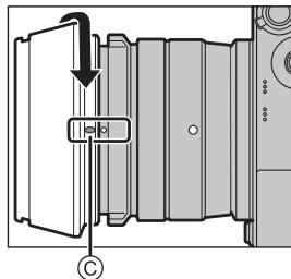
1 Rotate the decoration ring Ⓐ in the direction of the arrow to remove it.
2 Align the mounting index Ⓑ on the lens hood with the mark on the tip of the lens.
3 Rotate the lens hood in the direction of the arrow until it clicks into place, and align the stop position © on the lens hood with the index on the tip of the lens.
2

3

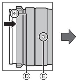
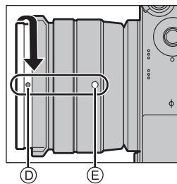
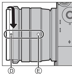
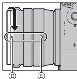
■ Attaching the decoration ring
- Before attaching the decoration ring, make sure to remove the lens cap.
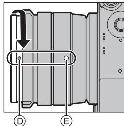
1 Align the mounting position Ⓓ on the decoration ring with a position approximately 90° away from the lens fitting mark Ⓔ to fit the decoration ring into place.
2 Rotate the decoration ring in the direction of the arrow to align the mounting position Ⓓ on the decoration ring with the lens fitting mark Ⓔ.
1
2

Specifications
| Power Consumption: | When the interchangeable lens (H-X015) is used |
| 2.2 W (When recording) | |
| 1.5 W (When playing back) |
| Minimum Illumination | Approx. 5 lx (when i-Low light is used, the shutter speed is 1/25th of a second) |
| Flash | Flash range: Approx. 0.5 m (1.6 feet) to 9.4 m (31 feet) (When [ISO AUTO] is set) |
| Mass | Approx. 319 g/0.70 lb [with the interchangeable lens (H-X015), card and battery] |
Refer to the operating instructions for other specifications.
Interchangeable Lens (H-X015) "LEICA DG SUMMILUX 15 mm/F1.7 ASPH."
| Focal length | f=15 mm(35 mm film camera equivalent: 30 mm) |
| Aperture type | 7 diaphragm blades/circular aperture diaphragm |
| Maximum aperture | F1.7 |
| Minimum aperture value | F16 |
| Lens construction | 9 elements in 7 groups (3 aspherical lenses) |
| Nano surface coating | Yes |
| In focus distance | 0.2 m (0.66 feet) to (from the focus distance reference line) |
| Maximum image magnification | 0.1 × (35 mm film camera equivalent: 0.2 × ) |
| Optical Image Stabiliser | Not available |
| [AF/MF] switch | Available (Switching AF/MF) |
| Mount | “Micro Four Thirds Mount” |
| Angle of view | 72° |
| Filter diameter | 46 mm |
| Max. diameter | Approx. 57.5 mm (2.3 inch) |
| Overall length | Approx. 36 mm (1.4 inch)(from the tip of the lens to the base side of the lens mount) |
| Mass | Approx. 115 g (0.25 lb) |
- LEICA is a registered trademark of Leica Microsystems IR GmbH. SUMMILUX is a registered trademark of Leica Camera AG. The LEICA DG lenses are manufactured using measurement instruments and quality assurance systems that have been certified by Leica Camera AG based on the company's quality standards.
■ Approximate operating time and number of recordable pictures
When the interchangeable lens (H-X015) is used
| Recording still pictures (By CIPA standard in Programme AE Mode) | |
| • Number of recordable pictures: Approx. 240 pictures• Recording time: Approx. 120 min | |
| Recording motion pictures | |
| [AVCHD](Recording with picture quality set to [FHD/50i]) | • Recordable time: Approx. 90 min |
| • Actual recordable time: Approx. 45 min | |
| [MP4](Recording with picture quality set to [FHD/25p]) | • Recordable time: Approx. 90 min |
| • Actual recordable time: Approx. 45 min | |
| Playback | |
| • Playback time: Approx. 160 min | |
3

2

Spécifications
3

2

Specifiche
3

2

Specifications
3

2

Dane techniczne
3

2
Especificaciones
3

2
Especificações
3
2

Egenskaper
3

2
Specifikationer
3

2
Tekniset tiedot
Brand : PANASONIC
Model : DMC-GM1LEG
Category : Camera