
PowerEdge 2650 - Server DELL - Free user manual and instructions
Find the device manual for free PowerEdge 2650 DELL in PDF.
| Product Type | Rack server 2U |
| Dimensions (H x W x D) | 8.68 x 48.26 x 71.12 cm |
| Weight | 38.5 kg |
| Power Supply | 650 W, redundant |
| Processors | Intel Xeon up to 2.8 GHz, dual processor capable |
| Memory | DDR-SDRAM PC-2100 266 MHz, up to 12 GB, with redundant memory support |
| Hard Drives | SCSI interface, shared backplane 2/3 |
| Network Connectivity | Broadcom NetXtreme Gigabit Ethernet, Wake-on-LAN support (10/100 Mbps standby) |
| Key Technologies | Hyper-Threading, redundant memory, console redirection (ANSI) |
| Expansion Slots | PCI connectors, secondary SCSI daughter card |
| Maintenance and Cleaning | Unplug before cleaning; use a soft dry cloth |
| Safety | Rack locking, grounding, safety instructions in the manual |
| Spare Parts and Repairability | Memory modules, hard drives, expansion cards, SCSI daughter card, fans |
| General Information | Brand DELL, model PowerEdge 2650, year 2003 |
Frequently Asked Questions - PowerEdge 2650 DELL
User questions about PowerEdge 2650 DELL
0 question about this device. Answer the ones you know or ask your own.
Ask a new question about this device
Download the instructions for your Server in PDF format for free! Find your manual PowerEdge 2650 - DELL and take your electronic device back in hand. On this page are published all the documents necessary for the use of your device. PowerEdge 2650 by DELL.
USER MANUAL PowerEdge 2650 DELL
Notes, Notices, and Cautions

NOTE: A NOTE indicates important information that helps you make better use of your computer.

NOTICE: A NOTICE indicates either potential damage to hardware or loss of data and tells you how to avoid the problem.

CAUTION: A CAUTION indicates a potential for property damage, personal injury, or death.
Information in this document is subject to change without notice.
© 2003 Dell Inc. All rights reserved.
Reproduction in any manner whatsoever without the written permission of Dell Inc. is strictly forbidden.
Trademarks used in this text: Dell and the DELL logo are trademarks of Dell Inc.; Microsoft and Windows are registered trademarks of Microsoft Corporation; Intel is a registered trademark and Xeon is a trademark of Intel Corporation.
Other trademarks and trade names may be used in this document to refer to either the entities claiming the marks and names or their products. Dell Inc. disclaims any proprietary interest in trademarks and trade names other than its own.
This document provides updated information about the following topics for your system:
- Installing the SCSI cable strain-relief bracket
- System board connectors for memory modules
- Expansion card installation guidelines
• Installing the SCSI backplane daughter card - Broadcom NetXtreme Gigabit Ethernet Server Adapter
- Microprocessor features
- System features
- Console redirection special key functions
- System memory features
Installing the SCSI Cable Strain-Relief Bracket
1 Turn off the system, including any attached peripherals, and disconnect the system from the electrical outlet.
2 Ensure that the system is pushed back as far as possible in the rack.
3 Connect any SCSI cables to the system before connecting the I/O cables.
NOTE: To use the strain-relief bracket, only two SCSI cables can be connected to each I/O slot at a time. The cables cannot be stacked, one above the other; they must be either side-by-side or placed diagonally to each other.
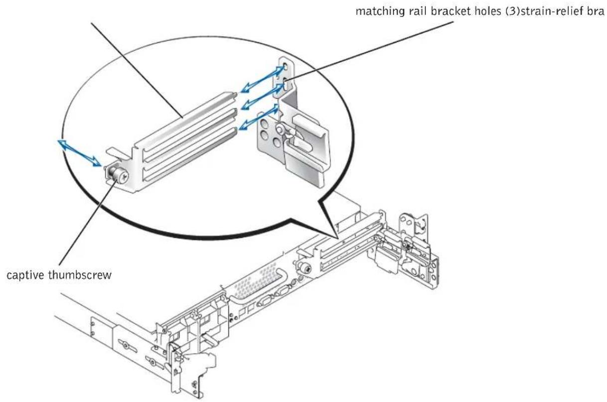
4 Install the strain-relief bracket to the back of the system.
a Insert the ends of the three long portions of the strain-relief bracket into the three matching holes in the rail bracket (see Figure 1-1).
b Secure the captive thumbscrew to the back of the system (see Figure 1-1).
5 Connect the I/O cables to the back of the system.
For information on routing system cables, see your Rack Installation Guide.
Figure 1-1. Installing the Strain-Relief Bracket
text_image
matching rail bracket holes (3)strain-relief bra captive thumbscrewSystem Board Connectors for Memory Modules
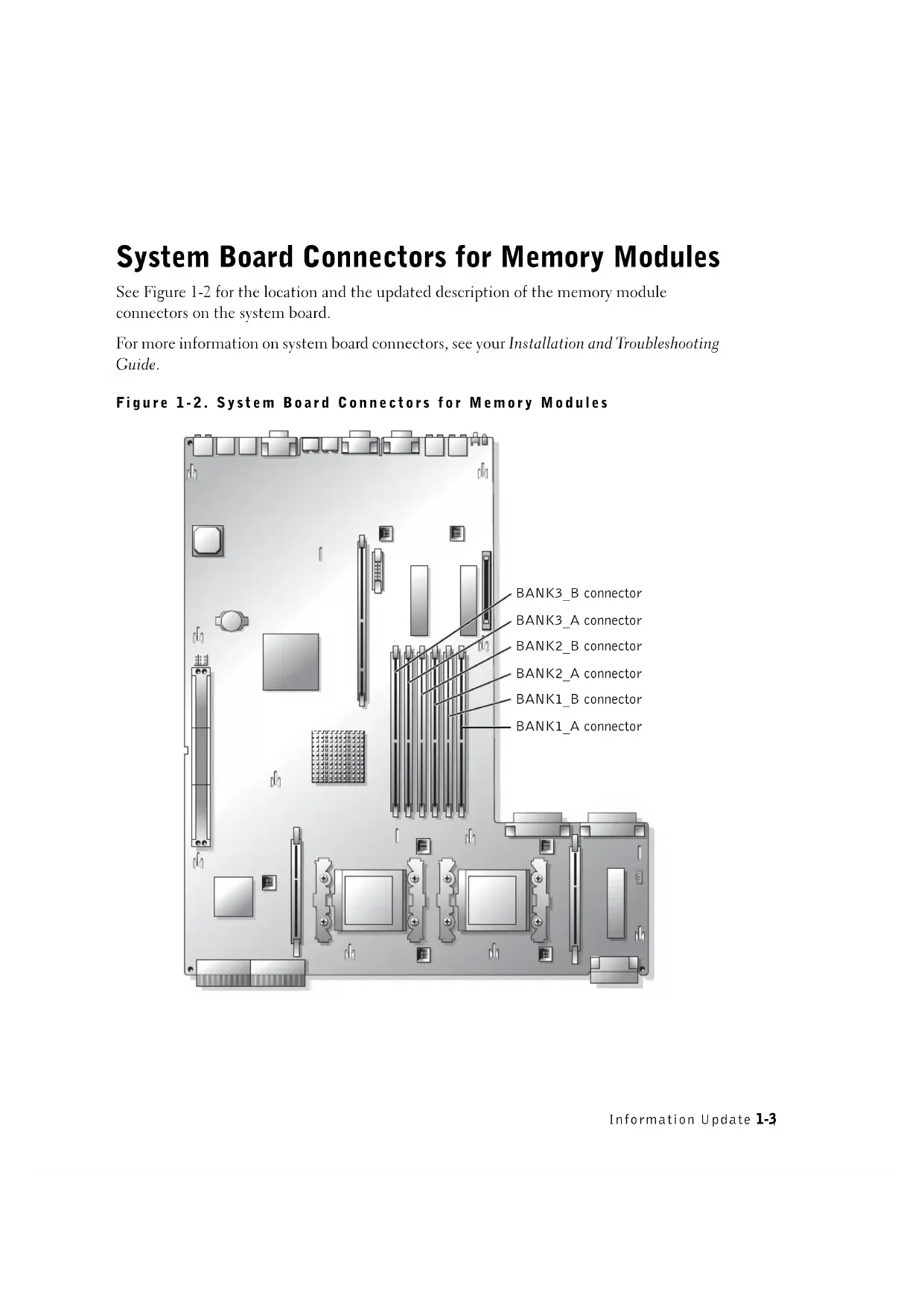
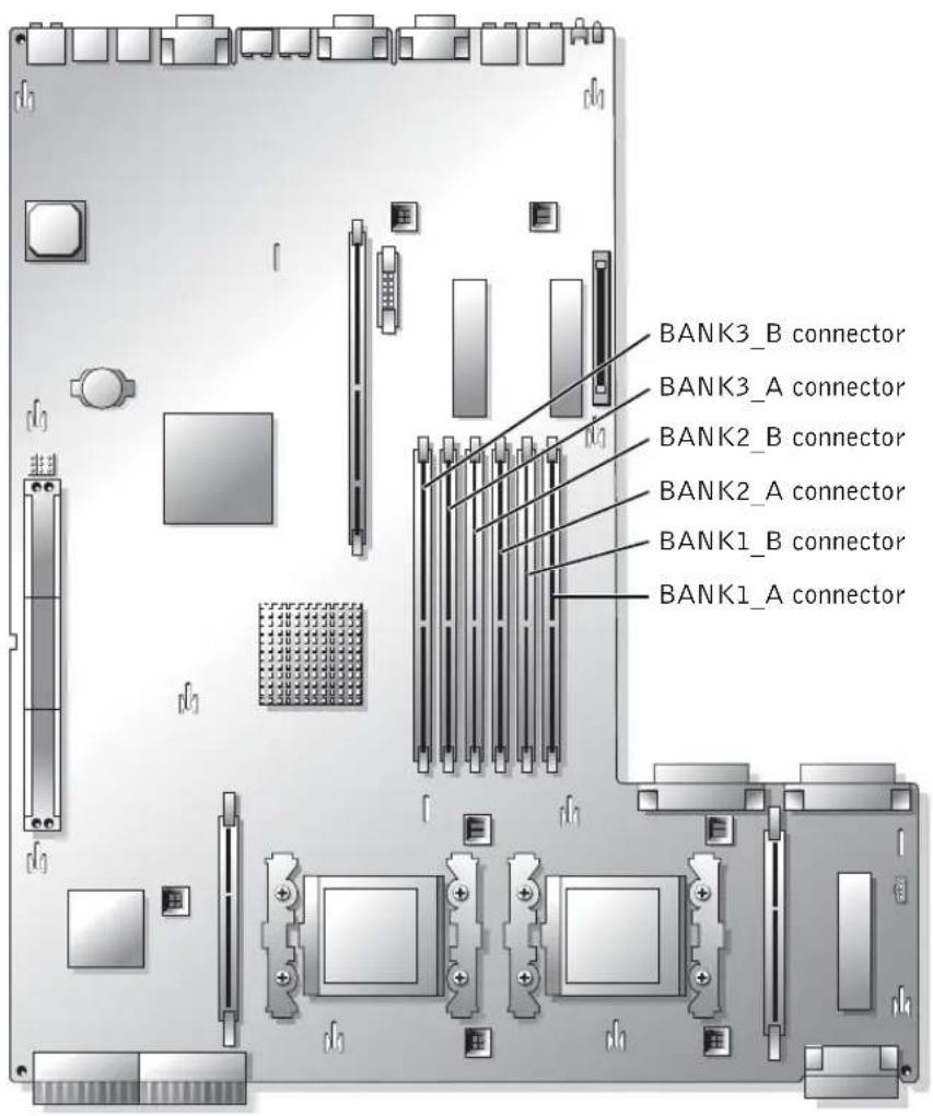
See Figure 1-2 for the location and the updated description of the memory module connectors on the system board.
For more information on system board connectors, see your Installation and Troubleshooting Guide.
Figure 1-2. System Board Connectors for Memory Modules
text_image
BANK3_B connector BANK3_A connector BANK2_B connector BANK2_A connector BANK1_B connector BANK1_A connectorExpansion Card Installation Guidelines
- Do not install full-length expansion cards in slot 1.
- You can install expansion cards of different operating speeds on the same bus; however, the bus will operate at the slowest operating speed of the cards on that bus.
See Figure A-4 in your Installation and Troubleshooting Guide to identify expansion card slots and buses.
Installing the SCSI Backplane Daughter Card

NOTICE: Before installing a SCSI backplane daughter card, back up your data to prevent data loss.
To operate the SCSI backplane in a 2/3 split configuration, you must install a daughter card. For more information on installing the SCSI backplane daughter card, see your Installation and Troubleshooting Guide.
Broadcom NetXtreme Gigabit Ethernet Server Adapter
When a Broadcom NetXtreme Gigabit Ethernet Server Adapter is installed and wake on LAN (WOL) is enabled, your system's connection speed is 10/100-Mbps. The Broadcom NetXtreme Gigabit Server Adapter only supports 10/100-Mbps links when WOL is enabled and the system is in Microsoft ^® Windows ^® 2000 Server and Advanced Server hibernation.
When the operating system loads and the correct drivers are installed, your supported connection speed is 10/100/1000 Mbps. It is recommended that when WOL support is required, the Broadcom NetXtreme Gigabit Server Adapter is connected to a 10/100/1000 link partner in autonegotiation mode.
WOL is supported on only one Ethernet port in the system, which does not include the system management port. If you are using an integrated NIC for this purpose, you must use the NIC 1 connector. WOL is not supported on Broadcom NetXtreme Gigabit 5703 Ethernet adapters.
Microprocessor Features
The Intel ^® Xeon ^™ microprocessors in your system provide NetBurst microarchitecture and Hyper-Threading Technology to significantly increase microprocessor performance. Hyper-Threading allows one physical microprocessor to appear as two logical processors to the operating system and application programs. Hyper-Threading also allows each microprocessor to simultaneously execute multiple tasks using shared hardware resources.
These new technology features in the microprocessor provide the following for multithreaded tasks:
• Enhanced system performance
- Improved reaction and response time for the system
- Increased number of users that a system can support
- Increased number of transactions that can be executed simultaneously by the system
The CPU Information option in the System Setup program's main screen displays information about the different processors in the system (speed, cache size, and others.). After the microprocessor information is displayed, you can enable or disable Hyper-Threading by changing the setting of the Logical Processor option. (The default is Enabled.)
You can find more information about Hyper-Threading Technology at developer.intel.com.
System Features
Your system contains the following new system features:
- Up to two Xeon microprocessors with a front-side bus speed of 533 MHz, an internal operating speed of at least 2.0 GHz, and at least 512 KB of internal cache.

NOTE: Your system does not support microprocessors with different front-side buses.
• PC-2100 registered 266 MHz DDR SDRAM memory modules.
Console Redirection Special Key Functions
Table 1-1 lists additional ANSI escape sequences that represent a special key or function. For additional information on console redirection and configuring special key functions, see "Console Redirection" in your User's Guide.

NOTE: ANSI escape-sequence key combinations listed in Table 1-1 are case-sensitive. For example, to generate the character
Table 1-1. Additional ANSI Escape Sequences
| <Home> | ANSI | |
| ANSI | ||
| ANSI | ||
| ANSI | ||
| ANSI | ||
| ANSI | ||
| ANSI | ||
| ANSI | ||
| ANSI | ||
System Memory Features
Your system features redundant memory, which provides the system with a failover memory bank when an active memory bank has excessive single-bit errors. This failover occurs without the need to halt or restart the system. You can enable this feature in the System Setup program. For more information about the System Setup program, see your User's Guide.
To enable the Redundant Memory option in the System Setup program, all memory slots in the system must be populated, and all memory modules must be of the same type and size.
The redundant memory options vary according to the number of populated memory banks and whether identical memory modules are installed in each bank:
- Disabled — One or more banks are not populated, or not all memory modules are of the same type and size.
- Disabled and Spare Bank Enabled — All three memory banks are populated with memory modules of the same size and type.
Dell™ 系统
信息更新
注、注意和警告

September 2003 P/N 9Y853 Rev A03
Broadcom NetXtreme Gigabit Ethernet Server Adapter
- Broadcom NetXtreme Gigabit Ethernet Server Adapter
- マイクロプロセッサの機能
・システムの機能
Broadcom NetXtreme Gigabit Ethernet Server Adapter
© 2003 Dell Inc. All rights reserved.