
PowerEdge 2600 - Server DELL - Free user manual and instructions
Find the device manual for free PowerEdge 2600 DELL in PDF.

| Product type | Server |
| Brand | Dell |
| Model | PowerEdge 2600 |
| Form factor | Tower or rack (5U) |
| Processor | Intel Xeon up to 3.06 GHz, dual processor capable |
| Memory (RAM) | Up to 8 GB DDR SDRAM |
| Storage | Up to 6 hot-swap SCSI hard drives |
| Power supply | Dual redundant 750 W power supplies |
| Operating system | Microsoft Windows Server, Linux |
| Network connectivity | Integrated Gigabit Ethernet controller |
| Key features | Enterprise server with remote management, RAID, hot-swap |
| Maintenance and cleaning | Regularly dust the fans and vents. Use a lint-free cloth. |
| Security | Chassis intrusion detection, BIOS password, front panel lock |
| Spare parts and repairability | Processor, memory, hard drives, fans, power supply units, VRM modules |
| General information | User manual and installation guide available in PDF format |
Frequently Asked Questions - PowerEdge 2600 DELL
User questions about PowerEdge 2600 DELL
0 question about this device. Answer the ones you know or ask your own.
Ask a new question about this device
Download the instructions for your Server in PDF format for free! Find your manual PowerEdge 2600 - DELL and take your electronic device back in hand. On this page are published all the documents necessary for the use of your device. PowerEdge 2600 by DELL.
USER MANUAL PowerEdge 2600 DELL
Microprocessor Upgrade Installation Guide
微处理器升级安装指南
Microprocessor Upgrade Installation Guide
Notes, Notices, and Cautions
NOTE: A NOTE indicates important information that helps you make better use of your computer.
NOTICE: A NOTICE indicates either potential damage to hardware or loss of data and tells you how to avoid the problem.
CAUTION: A CAUTION indicates a potential for property damage, personal injury, or death.
Information in this document is subject to change without notice.
© 2002-2003 Dell Computer Corporation. All rights reserved.
Reproduction in any manner whatsoever without the written permission of Dell Computer Corporation is strictly forbidden.
Trademarks used in this text: Dell and the DELL logo are trademarks of Dell Computer Corporation.
Other trademarks and trade names may be used in this document to refer to either the entities claiming the marks and names or their products. Dell Computer Corporation disclaims any proprietary interest in trademarks and trade names other than its own.
March 2003 P/N 9D904 Rev. A05
This document provides instructions about adding or replacing microprocessors. To take advantage of future options in speed and functionality, you can add secondary microprocessors or replace microprocessors in your system.
NOTICE: Before you add or replace a microprocessor, check the latest system BIOS information on the Dell Support website at support.dell.com, and upgrade the BIOS if necessary.
Each microprocessor and its associated cache memory are contained in a pin-grid array (PGA) package that is installed in a ZIF socket on the system board. The following subsection describes how to install or replace the microprocessor in either the primary or secondary microprocessor sockets.
NOTE: In a single microprocessor system, the microprocessor must be installed in the primary microprocessor socket.
Adding or Replacing a Microprocessor
NOTICE: The secondary microprocessors must be the same speed as the primary microprocessor.
In addition to the ZIF socket for the primary microprocessor on the system board, other ZIF sockets might be present to accommodate secondary microprocessors.
The following items are included in the microprocessor upgrade kit:
- A microprocessor
- A heat sink
- Heat-sink retention clip(s)
- A VRM, if applicable
Your upgrade kit may also include a cooling fan.
CAUTION: Before you perform this procedure, read the safety instructions in your System Information document.
1 Turn off the system, including any peripherals, and disconnect the power cable from the electrical outlet.
2 Open the system doors, or remove the system cover (see your Installation and Troubleshooting Guide).
CAUTION: See "Protecting Against Electrostatic Discharge" in the safety instructions in the System Information document.
3 Remove the cooling shroud, if applicable (see your Installation and Troubleshooting Guide).
4 If you are upgrading an existing microprocessor, remove the microprocessor heat sink.

NOTE: If a cooling fan is mounted on the heat sink, you can remove the heat sink without removing the fan. However, you can remove the fan to provide easier access to the heat-sink retention clip(s). For information on removing a cooling fan, see your Installation and Troubleshooting Guide.
a Remove the retention clip(s) securing the heat sink to the microprocessor by pressing down firmly on the retention clip tab, and then removing the clip from the heat sink.

CAUTION: The microprocessor and heat sink can become extremely hot. Be sure they have had sufficient time to cool before handling.

NOTICE: Never remove the heat sink from a microprocessor unless you intend to remove the microprocessor. The heat sink is necessary to maintain proper thermal conditions.

NOTICE: After removing the heat sink, place it upside down on a flat surface to prevent the thermal interface material from being damaged or contaminated.
b Remove the heat sink. See your Installation and Troubleshooting Guide for information on removing the heat sink.
5 Swing the socket release lever upward to the fully open position (see Figure 1-1).

NOTICE: Be careful not to bend any of the pins when removing the microprocessor. Bending the pins can permanently damage the microprocessor.
6 Lift the microprocessor out of the socket and leave the release lever in the open position so that the socket is ready for the new microprocessor.

NOTICE: Be careful not to bend any of the pins when unpacking the microprocessor. Bending the pins can permanently damage the microprocessor.
7 Unpack the new microprocessor.
If any of the pins on the microprocessor appear bent, see "Getting Help" in your Installation and Troubleshooting Guide.
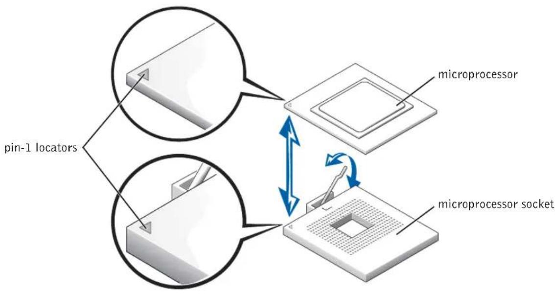
Figure 1-1. Removing and Replacing the Microprocessor

NOTICE: Positioning the microprocessor incorrectly can permanently damage the microprocessor and the system when you turn on the system. When placing the microprocessor in the ZIF socket, be sure that all of the pins on the microprocessor go into the corresponding holes. Be careful not to bend the pins.
8 Install the microprocessor in the socket (see Figure 1-1).
a Ensure that the microprocessor socket release lever is in the fully open position.
b Align pin 1 on the microprocessor with pin 1 on the microprocessor socket.
c With pin 1 of the microprocessor and socket aligned, set the microprocessor lightly in the socket and ensure that all pins are matched with the correct holes in the socket.
Because the system uses a ZIF microprocessor socket, there is no need to use force (which could bend the pins if the microprocessor is misaligned). When the microprocessor is positioned correctly, it should drop down into the socket with minimal pressure.
d When the microprocessor is fully seated in the socket, rotate the socket release lever back down until it snaps into place, locking the microprocessor in the socket.
9 Install the heat sink.
- If the heat sink provided has a protective cover on the underside of the heat sink, remove and discard the cover to expose the thermal grease or foil thermal interface material, and then place the heat sink on the microprocessor.
- If heat-sink thermal grease is provided, clean the heat sink and apply the thermal grease before placing the heat sink on the microprocessor.

NOTICE: To avoid possible damage to the microprocessor, you must align the heat sink so that the triangular mark on the heat sink points toward the triangular mark on the system board, if applicable.

Orient the heat-sink retention clip as shown in your Installation and Troubleshooting Guide.

I took the end of the clip without the release tab over the tab on the edge of the socket.

Press down on the release tab until the hole on the clip latches onto the ZIF socket tab.

NOTICE: If a cooling fan is provided with your upgrade kit, you must install the fan on the microprocessor heat sink to provide proper thermal conditions. For information on installing a cooling fan, see your Installation and Troubleshooting Guide.

If a cooling fan is provided with your upgrade kit or if you removed a cooling fan earlier in this procedure, install the fan on the microprocessor heat sink.
14 If applicable, install the VRM(s):
a If you are adding a secondary microprocessor, examine the VRM to ensure that it is the correct VRM for your system.
b Insert the VRM in the appropriate secondary VRM connector, ensuring that the latches at each end of the connector engage (see Figure 1-2).
c If you received two VRMs with the upgrade kit, replace the primary VRM already installed in the system with one of the VRMs from the upgrade kit.

NOTE: The system does not support mismatched VRMs.
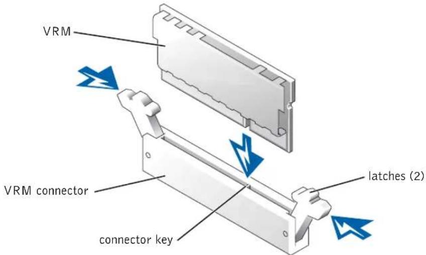
Figure 1-2. Installing a VRM
15 Replace the cooling shroud, if applicable (see your Installation and Troubleshooting Guide).
16 Close the system doors, or replace the system cover (see your Installation and Troubleshooting Guide).
17 Reconnect your system and peripherals to their electrical outlets, and turn them on. As the system boots, it detects the presence of the new processor and automatically changes the system configuration information in the System Setup program.

NOTE: After you access the inside of the system, the chassis intrusion detector will cause an alert message to be displayed at the next system startup. This message is stored in the system's nonvolatile random-access memory (NVRAM). To clear this message log, see your systems management software documentation.
18 Enter the System Setup program and ensure that the microprocessor categories match the new system configuration. For instructions about using the System Setup program, see your User's Guide.
19 Run the system diagnostics to verify that the new microprocessor is operating correctly. See your Installation and Troubleshooting Guide for information about running the diagnostics and troubleshooting any problems that may occur.
微处理器升级安装指南
注意和警告
Marz 2003 P/N 9D904 Rev. A05
© 2002-2003 Dell Computer Corporation.
Dell Computer Corporation's 1
Dell Dell Computer Corporation
Computer Corporation is a person who has acquired the right to use the technology in the market.
本部《聖堂》中,「聖堂」指聖殿。
主的*:叶iKroFIOR*,t#H+Hn#HJ#eDellJrWmSaiIt support.dell.com to BOS
18 System Setup icosofoe oio krofofofofofofofofofofofofofofofofofofofofofofofofofofofofofofofofofofofofofofofofofofofofofofofofofofofofofofofofofofofofofofofofofofofofofofofofofofofofofofofofofofofofofofofofofofofofofofofofofofofofo
19 丰斯默简于互元建在整行,新为成志中马以元互元建期者为合而之,动有不,当有之,自,自,自,自,自,自,自,自,自,自,自,自,自,自,自,自,自,自,自,自,自,自,自,自,自,自,自,自,自,自,自,自,自,自,自,自,自,自,自,自,自,自,自,自,自,自,自,自,自,自,白,白,白,白,白,白,白,白,白,白,白,白,白,白,白,白,白,白,白,白,白,白,白,白,白,白,白,白,白,白,白,白
Sistemas Dell™
Printed on recycled paper
中国印制
Imprimé en Chine
Gedruckt in China
中國家
Impreso en China
Printed in Ireland
爱尔兰印制
Imprimé en Ireland
Gedruckt in Ireland
ahalrelndeepf
Impreso en Irelanda
Brand : DELL
Model : PowerEdge 2600
Category : Server