
PowerEdge 1955 - Server DELL - Free user manual and instructions
Find the device manual for free PowerEdge 1955 DELL in PDF.
| Product type | Blade server |
| Dimensions (server module) | 1.75 x 5.0 x 20.0 inches (44.5 x 127 x 508 mm) |
| Weight (server module) | Approximately 6.8 kg |
| Power | 400 W maximum per server module (shared chassis power) |
| Supported processors | Up to two dual-core or quad-core Intel Xeon processors |
| Maximum RAM | 32 GB (8 DDR2 modules) |
| Hard drives | 2 bays for 2.5-inch SAS/SATA hard drives |
| Remote management functions | DRAC/MC module with Web interface, Telnet, serial console |
| Network connectivity | 2 LOM Ethernet ports per module, optional Gigabit mezzanine card |
| Integrated RAID | SAS 5iR controller supporting RAID 1 (mirroring) |
| Supported operating systems | Microsoft Windows Server, Red Hat Enterprise Linux, SUSE Linux Enterprise Server |
| Operating temperature | 10 to 35 °C |
| Operating humidity | 20 to 80% non-condensing |
| Maintenance and cleaning | Clean with a dry, lint-free cloth; avoid liquids. |
| Safety | Refer to the product information guide for safety instructions. |
| Spare parts and repairability | Contact Dell support for parts and repairs. |
Frequently Asked Questions - PowerEdge 1955 DELL
User questions about PowerEdge 1955 DELL
0 question about this device. Answer the ones you know or ask your own.
Ask a new question about this device
Download the instructions for your Server in PDF format for free! Find your manual PowerEdge 1955 - DELL and take your electronic device back in hand. On this page are published all the documents necessary for the use of your device. PowerEdge 1955 by DELL.
USER MANUAL PowerEdge 1955 DELL
Notes, Notices, and Cautions
NOTE: A NOTE indicates important information that helps you make better use of your computer.
NOTICE: A NOTICE indicates either potential damage to hardware or loss of data and tells you how to avoid the problem.
CAUTION: A CAUTION indicates a potential for property damage, personal injury, or death.
Information in this document is subject to change without notice. © 2006 Dell Inc. All rights reserved.
Reproduction in any manner whatsoever without the written permission of Dell Inc. is strictly forbidden.
Trademarks used in this text: Dell, the DELL logo, PowerEdge, PowerConnect, and Dell OpenManage are trademarks of Dell Inc.; Microsoft and Windows are registered trademarks and Windows Server is a trademark of Microsoft Corporation; SUSE is a registered trademark of Novell, Inc.; Red Hat is a registered trademark of Red Hat, Inc.
Other trademarks and trade names may be used in this document to refer to either the entities claiming the marks and names or their products. Dell Inc. disclaims any proprietary interest in trademarks and trade names other than its own.
May 2006 P/N PD382 Rev. A00
Contents
1 General System Configuration. 5
Other Documents You May Need 6
Initial Setup 7
Configuring Drive Mirroring 9
Additional Integrated Mirroring Guidelines 10
Connecting a USB Drive, Keyboard, and Mouse to the Server Module Front Panel 10
Installing an Operating System 10
Configuring the DRAC/MC Module 11
DRAC/MC Module Features 11
DRAC/MC Configuration Interface Options. 12
Web-Based Interface. 13
Serial or Telnet Console Interface 14
Using a Serial or Telnet Console 17
Redirecting the DRAC/MC Serial Console to the Ethernet Switch Module 19
Updating the DRAC/MC Module Firmware 19
Integrating the System Into the Network 22
Updating the PowerConnect Switch Module Firmware 27
Configuring the Cisco Catalyst Blade Switch 3030 29
Configuring the Cisco Switch Using a Web Browser and a Management Station. 29
Configuring the Swltch Using a Serial or Telnet Console 30
Gb Pass-through Module 31
Gb Pass-through Module Link Negotiations 31
Enabling PXE on a Gb Ethernet Daughter Card 31
Enabling PXE on the Broadcom TOE NIC Daughter Card 31
2 Configuring the KVM Switch Module 33
Configuring a KVM Using the OSCAR Interface and Direct Access 35
Running OSCAR. 35
Assigning Server Module Names. 35
Viewing and Selecting Slots and Server Modules 36
Scanning Your System 37
Changing the Display Behavior 38
Setting Console Security 39
OSCAR Navigation Summary 42
Configuring and Using the Avocent Digital Access KVM Module 43
Configuring the Avocent Digital Access KVM Module
Using the DRAC/MC. 43
Using the Video Viewer. 44
Using Virtual Media. 45
Updating the KVM Firmware. 47
Using the DRAC/MC Web-based Interface
to Update the KVM Firmware. 47
Using the RACADM Command Line Interface
to Update the KVM Firmware. 48
General System Configuration
This guide provides information on configuring your system and the server modules in your system. Additional information is available from additional sources. See "Other Documents You May Need" on page 6.
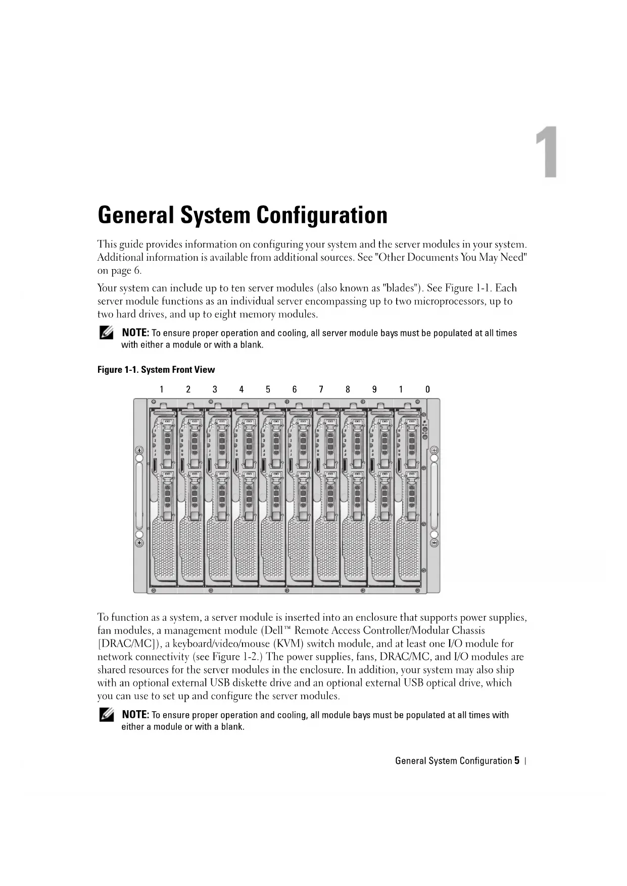
Your system can include up to ten server modules (also known as "blades"). See Figure 1-1. Each server module functions as an individual server encompassing up to two microprocessors, up to two hard drives, and up to eight memory modules.
NOTE: To ensure proper operation and cooling, all server module bays must be populated at all times with either a module or with a blank.
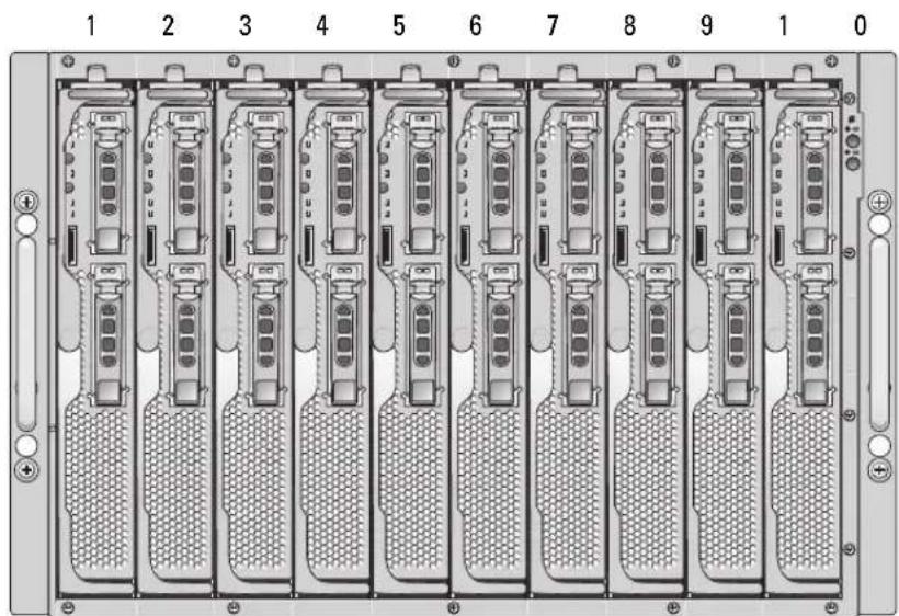
Figure 1-1. System Front View
To function as a system, a server module is inserted into an enclosure that supports power supplies, fan modules, a management module (Dell™ Remote Access Controller/Modular Chassis [DRAC/MC]), a keyboard/video/mouse (KVM) switch module, and at least one I/O module for network connectivity (see Figure 1-2.) The power supplies, fans, DRAC/MC, and I/O modules are shared resources for the server modules in the enclosure. In addition, your system may also ship with an optional external USB diskette drive and an optional external USB optical drive, which you can use to set up and configure the server modules.
NOTE: To ensure proper operation and cooling, all module bays must be populated at all times with either a module or with a blank.
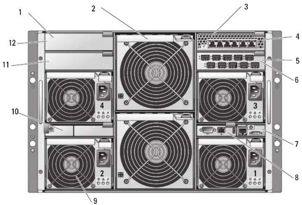
Figure 1-2. System Back View
1 I/O bay 2 2 fan modules (2) 3 Ethernet switch module
4 I/O bay 1 5 Fibre Channel pass-through
6 I/O bay 3
module
7 KVM module 8 DRAC/MC module 9 power supply modules (4)
10 blanks (2) 11 I/O bay 4 12 blanks (2)
Other Documents You May Need

The Product Information Guide provides important safety and regulatory information. Warranty information may be included within this document or as a separate document.
- The Rack Installation Guide or Rack Installation Instructions included with your rack solution describes how to install your system into a rack.
The Getting Started Guide provides an overview of initially setting up your system. - The Hardware Owner's Manual describes how to troubleshoot the system and install or replace system components.
- The Dell Remote Access Controller/Modular Chassis User's Guide provides detailed information on using the remote management features of the system.
-
The Dell PowerEdge Expandable RAID Controller 5iR Integrated Mirroring Guide describes using the integrated mirroring features.
-
The Baseboard Management Controller documentation provides detailed information on using the BMC.
- The Dell OpenManage Server Assistant User's Guide provides detailed information on the systems management software applications, as well as information on alternative upgrade paths.
- The network switch module documentation describes the features and how to use the network switch modules.
- Systems management software documentation describes the features, requirements, installation, and basic operation of the software.
- Operating system documentation describes how to install (if necessary), configure, and use the operating system software.
- Documentation for any components you purchased separately provides information to configure and install these options.
- Updates are sometimes included with the system to describe changes to the system, software, and/or documentation.
NOTE: Always check for updates on support.dell.com and read the updates first because they often supersede information in other documents.
- Release notes or readiness files may be included to provide last-minute updates to the system or documentation or advanced technical reference material intended for experienced users or technicians.
Initial Setup
1 Unpack the system and install it in a rack.
See the Getting Started Guide and Rack Installation Guide for more information.
2 Connect power to the power supplies.
NOTE: You should power up the enclosure prior to inserting server modules if Ethernet switch modules are installed. The Ethernet switch may take longer to boot than the server modules, which may cause functions like PXE to fail due to the Ethernet switch not being fully booted and ready to send packets.
3 Connect the keyboard, video, and mouse to the KVM module.
Figure 1-3 shows the basic cabling configuration for a KVM module.
Figure 1-3. KVM Module Basic Configuration
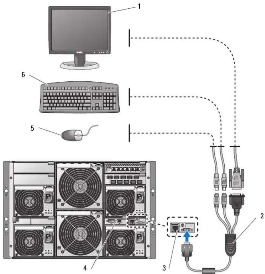
1 monitor 2 custom KVM cable 3 KVM module
4 DRAC/MC module 5 mouse 6 keyboard
4 If required, configure the hard drives for RAID 1 or integrated mirroring. Configure RAID 1 prior to installation of the operating system. See "Configuring Drive Mirroring" on page 9 for more information.
NOTE: If you ordered your server module configured for RAID 1, the drives in your server module are already configured.
5 If required, set up console redirection on the server module to either the BMC or to the DRAC/MC module serial port in the server module System Setup program. See "Serial or Telnet Console Interface" on page 14.
NOTICE: To prevent possible network disruptions, you must assign a static IP address, IP subnet mask, and gateway to the BMC before connecting to the network.
6 Assign a static IP address, IP subnet mask, and gateway to the BMC. For instructions, see the Dell OpenManage Baseboard Management Controller User's Guide.
7 Connect a management station to the DRAC/MC serial port using a null modem cable. See Figure 1-4.
NOTICE: The DRAC/MC module and the network switch module(s) can be configured for DHCP. If you have a DHCP server on your network, the server will provide a dynamic IP address to the modules and will permit configuration using the network. If you configure the modules for DHCP, step 8 and step 10 are not required unless you need to configure a static IP address. See the Dell Remote Access Controller/Modular Chassis User's Guide and the switch module's documentation for instructions on how to configure those modules for DHCP.
8 Configure the DRAC/MC module with an IP address and the current time. See "Using a Serial or Telnet Consolc" on page 17. See the Dell Remote Access Controller/Modular Chassis User's Guide for additional configuration options.
9 If required, switch the serial console to the Ethernet switch module console interface using the DRAC/MC command line interface (CLI). See"Redirecting the DRAC/MC Serial Console to the Ethernet Switch Module" on page 19.
10 Assign IP addresses to the network switch modules using the serial port on the DRAC/MC module. See "Configuring the PowerConnect 5316M Ethernet Switch Module" on page 25 or "Configuring the Cisco Catalyst Blade Switch 3030" on page 29.
Configuring Drive Mirroring
NOTE: If you ordered your server module configured for RAID 1, drive mirroring is already enabled.
NOTE: Two drives must be installed to enable integrated mirroring.
Use the following procedures to configure drive mirroring (RAID 1) before installing an operating system on the server module. If an operating system is preinstalled, you may use the following instructions or use the array management software provided with the system. For detailed information, see the Dell SAS 5/iR Integrated and Adapter User's Guide.
1 Press <Ctrl> < C> during POST to start the Configuration Utility.
2 Select a controller from the Adapter List in the Configuration Utility.
3 Select the RAID Properties option.
4 Select Create IM Volume when you are prompted to create a virtual disk.
5 The next screen shows a list of disks that can be added to a virtual disk. Move the cursor to the RAID Disk column. To add a disk to the virtual disk, change "No" to "Yes" by pressing < + > , < - > , or the space bar.
NOTICE: Data on both disks will be lost. You should back up all data before performing these steps.
As disks are added, the Virtual Disk Size field will change to reflect the size of the new virtual disk. There are several limitations when creating an IM virtual disk:
- All disks must be either SAS or SATA physical disks. A mixture of SAS and SATA drives is not supported
- Disks must have 512-byte blocks and must not have removable media.
- There must be 2 physical disks in an IM virtual disk.
7 Press < C > and then select Save changes when the virtual disk has been fully configured.
Press <f^3> to confirm that existing data will be lost with the creation of the virtual disk. The Configuration Utility will pause while the virtual disk is being created.
NOTE: IM provides protection against the failure of a single physical disk. When a disk fails, the physical disk can be replaced and the data re-mirrored to the physical disk, maintaining data integrity.
Additional Integrated Mirroring Guidelines
- The hard-drive status indicator does not display any status information until after the operating system driver initialization has occurred. To check for status information of a hard drive prior to operating system load, use <Ctrl> < C> during POST. During normal operation, the status indicator is off.
NOTE: The hard-drive activity indicator functions normally before and after the operating system driver initialization.
- Any replacement drives should be blank and not previously configured.
- You should replace hard drives in an integrated-mirror configuration with drives of the same capacity.
- After removing a hard drive in a hot-pluggable environment, wait at least 30 seconds prior to installing the new hard drive.
Connecting a USB Drive, Keyboard, and Mouse to the Server Module Front Panel
If you need to connect a USB drive (DVD-ROM, CD-ROM, or diskette drive), USB keyboard, and USB mouse to the server module front panel, connect a powered USB hub to one of the two front panel USB connectors, and then connect the drive, keyboard, and mouse to the powered USB hub.
NOTE: The optional DVD-ROM drive requires two USB 2.0 ports.
Installing an Operating System
NOTICE: If you install an operating system on a server module and your system uses an Avocent Digital Access KVM module, you must connect the monitor to the KVM module rather than the server module front panel.
Configuring the DRAC/MC Module
This section includes general configuration information for the DRAC/MC module. For detailed information on configuring the DRAC/MC and using the remote management features of the DRAC/MC, see the Dell Remote Access Controller/Modular Chassis User's Guide.
DRAC/MC Module Features
The DRAC/MC provides serial and Ethernet management ports, a status indicator when redundant DRAC/MCs are installed, and status indicators for the DRAC/MC (see Figure 1-4). Table 1-1 provides information about the status indicators.

NOTICE: The DRAC/MC must have a firmware version of 1.3 or later.

NOTICE: To support redundant DRAC/MC operation, both modules must have firmware version 1.3 or later. Mixing two DRAC/MC modules with firmware versions earlier than 1.3 may cause the enclosure to power down I/O modules in bays I/O 3 and I/O 4 without user intervention. See "Updating the DRAC/MC Module Firmware" on page 19 for information on updating the firmware.
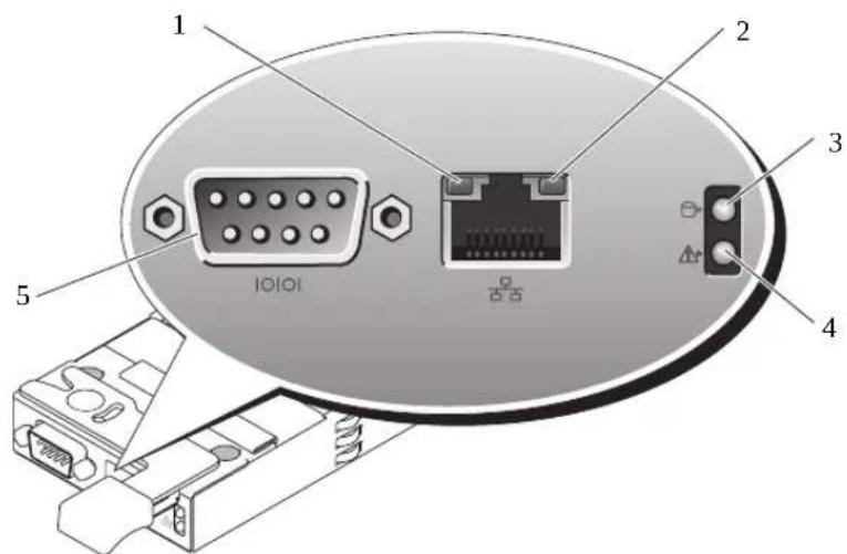
Figure 1-4. DRAC/MC Module Features
1 activity indicator 2 link indicator 3 primary/standby indicator
(redundant DRAC/MC configurations only)
4 fault indicator 5 serial connector
Table 1-1. DRAC/MC Module Indicators
| Indicator Type Icon Activity | Indicator Code Indicator | ||
| Network interface controller link indicator | Off LAN is not linked. Green LAN is linked. | ||
| Network interface controller activity indicator | Off LAN is not active. Amber blinking Indicates that the DRAC/MC and the LAN are communicating. | ||
| Primary/standby indicator | Off The DRAC/MC is a backup for the primary DRAC/MC (redundant DRAC/MC configurations only) Green The DRAC/MC is active for systems management. Green blinking The DRAC/MC is in recovery mode or manufacturing mode. | ||
| Fault indicator Off The DRAC/MC is operating normally. | |||
| Amber In a single (nonredundant) configuration, the DRAC/MC failed. Amber blinking In a redundant configuration, this DRAC/MC failed. | |||
| Serial connector | 10101 | None | Used for a serial connection with a null modem cable. |
DRAC/MC Configuration Interface Options
You can configure the DRAC/MC and update DRAC/MC firmware using the following interfaces:
- Web-based interface - Enables you to access the DRAC/MC using a supported Web browser through the DRAC/MC NIC. See "Web-Based Interface" on page 13.
- Telnet - Provides access to serial and RACADM CLI commands, and text console redirection through the DRAC/MC network interface. See "Serial or Telnet Console Interface" on page 14.
Web-Based Interface
Supported Web Browsers
The DRAC/MC supports the following Web browsers:
- Microsoft Internet Explorer 6.0 (Service Pack 2)
- Mozilla 1.7.8 (Rcd Hat ® Enterprise Linux version 3 and version 4)
- Mozilla 1.7.8 (SUSE® Linux Enterprise Server)
- Mozilla Firefox 1.0.7 (Red Hat Enterprise Linux version 4)
- Mozilla Firefox 1.0.7 (SUSE Linux Enterprise Server version 9)
NOTE: Cookies and JavaScript must be enabled.
NOTE: When you run multiple DRAC/MC sessions using Mozilla or Firefox browsers, each browser window shares the same session.
To fix this issue in the Mozilla browser, configure the Mozilla Profile Manager to use separate profiles. Run the Mozilla Profile Manager from the operating system shell prompt by typing mozillaprofilemanager.
To fix this issue in Firefox, set the environment variable MOZ_NO remoteto 1. Changing the environment variable creates a separate profile for each window (or session).
NOTE: In Microsoft Internet Explorer, if the following configuration setting is selected Tools Internet Options Advanced Security Do not save encrypted pages to disk. deselect this option and restart Internet Explorer.
NOTE: For proper operation in the Microsoft Windows XP SP2 and Microsoft Windows Server™ 2003 SP1 operating systems, disable the Windows firewall.
See the latest DRAC/MC Readme located on the Dell Support website at support.dell.com for the latest list of supported Web browsers.
Accessing the DRAC/MC Web-Based Interface
1 Open a Web browser.
2 lypc https://
where
NOTE: The DRAC/MC default IP address is 192.168.0.120.
3 To log in, type your DRAC/MC user name and password.
NOTE: The DRAC/MC default user name is root and the default password is calvin.
For more information about using the DRAC/MC interface, see the online hclp or the Dell Remote Access Controller/Modular Chassis User's Guide.
Serial or Telnet Console Interface
The DRAC/MC supports a serial and Telnet interface for its command line interface (CLI) and has the capability to switch this interface to any server module or switch module within the system enclosure. The following subsections provide information about how to enable and configure a serial/Telnet console on the DRAC/MC.
Configuring the System Setup Program on the Server Module
To configure the System Setup program to redirect the text console from a server module to the DRAC/MC serial port or Tclnet interface, perform the following steps:
NOTE: You must perform the following sequence of commands locally. Once you have completed these steps, you can redirect the server console to the DRAC/MC remotely.
1 Turn on or restart your server module.
2 Press < F2> immediately after you see the following message:
3 Scroll down and select Integrated Devices.
4 Set the Integrated Devices options to the following settings: Remote Terminal Type-ANSI or VT100/V1200.
Redirection After Boot - Enabled

NOTE: If your terminal is in VT100 mode and you are unable to see the proper selection, go to the Properties menu and change the terminal mode to VT200. Your selection should now be visible. Any cursor movement causes you to lose the selection. If you lose your selection, switch back to VT100, and the selection is displayed again.
5 Press <Esc> to exit the server module's System Setup program.
Connecting to the DRAC/MC Using Minicom for Serial Console Emulation (Red Hat Enterprise Linux and SUSE Linux Enterprise Server)
Minicom is the serial port access utility for Red Hat Enterprise Linux and SUSE Linux Enterprise Server.
NOTE: To ensure that the text displays properly, use an Xterm window to display the Telnet console instead of the default window.
1 To start a new Xterm session, type xterm & at the command prompt.
2 Drag the lower right corner of the window with the mouse to resize it to 80 × 25 .
3 At the Xterm command prompt, typeminicom.
4 Refer to Table 1-2 and configure Minicom for serial console emulation.
Table 1-2. Minicom Settings for Serial Console Emulation
| Setting Description Required Setting | |
| Bits Per Second/Parity/Bits 115200 8NI | |
| Hardware flow control Yes | |
| Software flow control No | |
| Terminal emulation ANSI | |
| Modem dialing and parameter settings | Clear the init, reset, connect, and hangup settings so that they are blank |
| Window size 80 x 25 (to rcsizc, drag the lower-right corner of the window) | |
5 Select Save setup as config_name and press < Enter>.
6 Select Exit From Minicom and press
7 At the command shell prompt, type minicom
8 To expand the Minicom window to 80 × 25 , drag the corner of the window.
When the login screen is displayed, type your user name and password.
NOTE: If you are using Minicom for serial text console redirection to configure the DRAC/MC BIOS, it may be useful to turn on color in Minicom. To turn on color, at the command shell prompt type minicom -c on.
See "Using a Serial or Telnet Console" on page 17 for information on using the Telnet console. To exit Minicom, press <Ctrl> <a> <z> <x> .
Connecting to the DRAC/MC Using HyperTerminal for Serial Console Redirection (Windows Operating System)
HyperTerminal is the serial port access utility for the Windows operating system. To set the size of your console screen appropriately, use Hlilgracvc's HyperTerminal Private Edition version 6.3.
1 Connect the null modem cable to the serial port on the DRAC/MC module and to the client system.
2 Click the Start button, point to Programs Accessories Communications, and then click HyperTerminal
3 Enter a name for the new connection, select an icon, and then click OK.
4 In the Connect using: text box, select the COM port on the management station (for example, COM1) to which you have connected the DB-9 null modem cable and click OK
5 Configure the COM port settings as shown in Table 1-3, and then click OK.
Table 1-3.COM Properties Dialog Box Port Settings
| Setting Description Required Setting |
| Bits per second: 115200 |
| Data bits: 8 |
| Parity: None |
| Stop bits: 1 |
| Flow control: Hardware |
6 Click File Properties and click the Settings tab.
7 Set the Telnet terminal ID: to V1100.
8 Click Terminal Setup and set Screen Rows to 25.
9 Set Columns to 80 and click OK.
10 Click ASCII Setup..., select Wrap lines that exceed terminal width, and click OK. See "Using a Serial or Telnet Console" on page 17 for information on using the serial console.
Connecting to the DRAC/MC Using XTerm for Telnet Console Redirection (Red Hat Enterprise Linux and SUSE Linux Enterprise Server)
NOTE: When you are using the connect server-x command through a Telnet console to display the System Setup screens, set the terminal type to VT100 in System Setup for the Telnet session.
NOTE: Telnet is disabled on the DRAC/MC by default. To enable Telnet, use either the Web-based user interface Configuration tab, or use thecfgSerial object to configure the DRAC/MC using the RACADM CLI. For more information, see the Dell Remote Access Controller/Modular Chassis User's Guide.
When running Telnet with Red Hat Enterprise Linux or SUSE Linux Enterprise Server, perform the following steps:
NOTE: To ensure that the text is properly displayed, use an Xterm window to display the Telnet console instead of the default window provided by the Red Hat Enterprise Linux and SUSE Linux Enterprise Server installation.
1 Connect the null modem cable to the serial port on the DRAC/MC module and to the client system.
2 To start a new Xterm session, type xterm & at the command prompt.
3 Rcsizc the window to 80× 25 prior to using T'elnct.
4 To connect to the DRAC/MC, at the Xterm prompt, typetelnet
NOTE: The DRAC/MC default IP address is 192.168.0.120.
5 See "Using a Serial or Telnet Console" on page 17 for information on using the Telnet console.
Connecting to the DRAC/MC Using Microsoft Telnet for Telnet Console Redirection
Microsoft Telnet requires that you first enable Telnet in Windows Component Services. After Telnet is enabled, connect to the DRAC/MC by performing the following steps:
1 Open a command prompt.
2 Type telnet
NOTE: The DRAC/MC default IP address is 192.168.0.120.
3 See "Using a Serial or Telnet Console" on page 17 for information on using the Telnet console.
Using a Serial or Telnet Console
NOTE: If you are running the Windows XP or Windows Server 2003 operating system and experience problems in a DRAC/MC Telnet session, see the Microsoft Knowledge Base article 824810 on the Microsoft Support site at support.microsoft.com for more information and an available hotfix.
NOTE: On a Windows 2000 management station, pressing the <F2> key does not enter BIOS setup. To resolve this problem, use the Telnet client supplied with the Windows Services for UNIX® 3.5 download from Microsoft. You can download Windows Services for UNIX 3.5 from www.microsoft.com/windows/sfu/downloads/default.asp.
You can type serial commands or RACADM CLI commands in a serial or Telnet console. For more information, see "Using the DRAC/MC CLI Commands" in the Dell Remote Access Controller/Modular Chassis User's Guide.
1 Click OK.
The DRAC/MC application displays a login screen on the console monitor.
2 Log into the DRAC/MC using the default username root and password calvin.
The DRAC/MC CLI command prompt DRAC/MC: is displayed.
3 If the system enclosure is powered off, power on the enclosure using the following DRAC/MC CLI command:
racadm chassisaction -m chassis powerup
NOTE: The Ethernet switch module inserted into the I/O bay is powered on automatically when the system enclosure is powered on. For more information on configuring the system enclosure using the DRAC/MC CLI interface, see the Dell Remote Access Controller/Modular Chassis User's Guide.

NOTE: You should power up the enclosure prior to inserting server modules if Ethernet switch modules are installed. The Ethernet switch may take longer to boot than the server modules, which may cause functions like PXE to fail due to the Ethernet switch not being fully booted and ready to send packets.
4 To set the DRAC/MC time, type:
racadm setractime -d yyymmdhhmmss.mmmmmsoff
where:
- yyyy is a 4-digit year
- mm is the month
- dd is the day
- hh is the hour (24-hour clock)
- mm is the minute
- s is the second
- mmmmm is the number of microseconds
-S is a "+" or "-" indicating the sign of the offset
-Off is the offset in minutes
For example, Monday, May 25, 2004, at 1:30:15 PM would be represented as:
racadm setractime -d 20040525133015.000000-300
5 If required, assign a static IP address using the following DRAC/MC CLI command:
racadm setniccfg -s [
Obtain your network's specific address information from your network administrator. In the following example, 192.168.0.120 is the DRAC/MC default static IP address, 255.255.255.0 is the subnet mask address, and 192.168.1.1 is the gateway address.
racadm setniccfg -s 192.168.0.120 255.255.255.0 192.168.1.1
6 Press
7 Type racadm getniccfg and press < Enter>.
The current and static IP addresses are displayed.
NOTE: By default, Telnet is disabled.
8 To enable Telnet access to the DRAC/MC, use the following DRAC/MC CLI command:
racadm config -gcfgSerial -ocfgSerialTelnetEnable 1
9 If the serial console is disabled, you can enable the console remotely through the Telnet interface. To enable the serial console at the Telnet consoleDRAC/MC: prompt, type the following serial CLI commands:
racadm config -gcfgSerial -ocfgSerialConsoleEnable 1
racadm config -gcfgSerial -ocfgSerialTelnetEnable 1
Redirecting the DRAC/MC Serial Console to the Ethernet Switch Module
Redirect the DRAC/MC serial console to the Ethernet switch module internal serial console interface by entering the following command:
connect switch-n
where n is the system enclosure I/O module bay number in which the Ethernet switch module is installed.

NOTE: To switch back to the context of the DRAC/MC CLI command prompt, press <Enter> >
After the switch module is connected to the console, wait until the Ethernet switch module is fully booted. Observe the booting information being displayed on the terminal window and wait for the switch module prompt to appear. Press

NOTE: The switch module's system indicator is off when the module is enabled and operating normally. If the switch has been disabled by the DRAC/MC, or there are hardware or firmware issues, the indicator will turn green.
Updating the DRAC/MC Module Firmware

NOTICE: Updating your DRAC/MC firmware will disconnect your current network connection.
Use one of the following methods to update your DRAC/MC firmware:
- Web-based Interface — See "Using the DRAC/MC Web-based Firmware Update Interface" on page 20.
- RACADM CLI - See "Using the RACADM CLI to Update the DRAC/MC Firmware" on page 21.
Firmware Recovery Console - See "Using the Firmware Recovery Console" on page 22.
Using the DRAC/MC Web-based Firmware Update Interface
NOTICE: The DRAC/MC module(s) must use firmware version 1.3 or later.
To support redundant DRAC/MC operation, both modules must have firmware version 1.3 or later. Mixing DRAC/MC modules with firmware versions earlier than 1.3 may cause the enclosure to power down I/O modules in bays I/0 3 and I/0 4 without user intervention.
NOTICE: If you are updating a DRAC/MC module's firmware to version 1.3 or later, install version 1.1 or version 1.1.1 before installing the latest version (1.3 or later). Upgrading firmware from version 1.0 directly to version 1.3 or later is not supported.
NOTE: To facilitate the firmware upgrade, download a TFTP server from http://solarwinds.net. For information on installing and configuring the SolarWinds TFTP server, refer to the SolarWinds website.
NOTICE: Since the DRAC/MC uses a different MAC address during a firmware update, it sends a gratuitous ARP packet after completing the update. A switch with Spanning Tree Protocol enabled may block the ARP packet transmission. To avoid this issue, disable the Spanning Tree Protocol on the switch ports that are connected to all DRAC/MC modules during a firmware update.
1 Copy the binary file mgmt.bin to a TFTP server root directory.
2 Log on to the DRAC/MC Web-based user interface. See "Accessing the DRAC/MC Web-Based Interface" on page 13.
3 From the DRAC/MC Web-based user interface main window, click theUpdate tab.
4 In the Firmware Update window, enter the IP address of the TFTP server and the image name, mgmt.bin.
5 Click Update Firmware.
The firmware update process may take several minutes to complete. The DRAC/MC will then reset.
6 If you installed firmware version 1.1 or version 1.1.1 and want to update your DRAC/MC firmware to version 1.3 or later, repeat step 2 through step 5. Otherwise, go to step 7.
7 If your system is not configured with two DRAC/MC modules in a redundant configuration, you have completed the firmware update.
If your system is configured with two DRAC/MC modules in a redundant configuration and the DRAC/MC modules have firmware versions 1.1 or later, both modules will be updated from the same binary image. Perform the following steps if upgrading from firmware version 1.0:
a Remove the updated DRAC/MC module from the system.
b Insert the remaining DRAC/MC module into the system.
c Repeat step 2 through step 6.
NOTICE: You must clear the Web browser cache after completing the firmware update to ensure that all new Web-based interface pages are reloaded when using the interface.
8 After the update is complete, clear the Web browser cache. See "Clearing the Web Browser Cache" on page 22.
Using the RACADM CLI to Update the DRAC/MC Firmware

NOTICE: If you are updating your DRAC/MC module firmware to version 1.3 or later, install version 1.1 or version 1.1.1 before you install the new version (1.3 or later). Upgrading your firmware from version 1.0 directly to version 1.3 or later is not supported.
1 If your system is configured with two DRAC/MC firmware version 1.0 modules, remove one DRAC/MC module from the system.
2 Copy the binary file mgmt.bin to a TFTP server root directory.
3 Log on to the DRAC/MC Telnet or serial interface. See "Using a Serial or Telnet Console" on page 17.
4 From the Telnet or serial interface, type a command line similar to the following example: racadm fwupdate -a
The update process may take several minutes to complete. The DRAC/MC will then reset.
From the remote RACADM interface, type a command line similar to the following example:
racadm -r
The TFTP download and firmware update process may take several minutes to complete. After the update completes, the DRAC/MC will reset.

NOTE: The remote RACADM utility version 5.0.0 is compatible with DRAC/MC version 1.3 and later.
5 If you installed firmware version 1.1 or version 1.1.1 and want to update your DRAC/MC firmware to version 1.3 or later, repeat step 3 and step 4. Otherwise, go to step 6.
6 If your system is not configured with two DRAC/MC modules in a redundant configuration, you have completed the firmware update.
If your system is configured with two DRAC/MC modules in a redundant configuration and the DRAC/MC modules have firmware versions 1.1 or later, both modules will be updated from the same binary image. Perform the following steps if upgrading from firmware version 1.0:
a Remove the updated DRAC/MC module from the system.
b Insert the remaining DRAC/MC module into the system.
c Repeat step 3 through step 5.
7 If you will use the DRAC/MC Web-based interface after updating the firmware, clear the Web browser cache to ensure that all new Web-based interface pages are reloaded. See "Clearing the Web Browser Cache" on page 22.
Clearing the Web Browser Cache
Clearing the Web Browser Cache With Internet Explorer
1 From the drop-down menu, select Tools Internet Options.
2 In the Internet Options window, click the General tab, and under Temporary Internet Files, click Delete Files....
3 Select Delete all offline content.
4 Click OK twice.
5 Close and restart the Web browser.
Clearing the Web Browser Cache With Mozilla or Firefox
1 From the drop-down menu, select Edit Preferences.
2 In the Preferences window, select Advanced Cache.
3 Select Clear Disk Cache.
4 Select Clear Memory Cache.
5 Click OK.
6 Close and restart the browser.
Using the Firmware Recovery Console
If the firmware becomes corrupted, the DRAC/MC will boot to the Firmware Recovery Console. To view the console, attach a null modem cable from the DRAC/MC serial port to your management station and run a terminal emulation software package to attach to the DRAC/MC. The console allows you to install the firmware through a TFTP server or through the DRAC/MC serial port.
Integrating the System Into the Network
Your system is essentially a self-contained network. Table 1-4, Table 1-5, and Table 1-6 show the mapping of the internal and external ports.
Table 1-4. Internal Network Port Mapping
| Module Port I/O Bay 1 I/O Bay 2 |
| Server module 1 |
| LOM 1 1/1 |
| LOM 2 1/1 |
| Server module 2 |
| LOM 1 1/2 |
| LOM 2 1/2 |
| Server module 3 |
| LOM 1 1/3 |
| LOM 2 1/3 |
| Server module 4 |
| LOM 1 1/4 |
| LOM 2 1/4 |
| Server module 5 |
| LOM 1 1/5 |
| LOM 2 1/5 |
| Server module 6 |
| LOM 1 1/6 |
| LOM 2 1/6 |
| Server module 7 |
| LOM 1 1/7 |
| LOM 2 1/7 |
| Server module 8 |
| LOM 1 1/8 |
| LOM 2 1/8 |
| Server module 9 |
| LOM 1 1/9 |
| LOM 2 1/9 |
| Server module 10 |
| LOM 1 1/10 |
| LOM 2 1/10 |
Table 1-5. Uplink (External Ports) on Network Switch
| Network Switch 1 Network Switch 2 |
| 1/11 1/11 |
| 1/12 1/12 |
| 1/13 1/13 |
| 1/14 1/14 |
| 1/15 1/15 |
| 1/16 1/16 |
Table 1-6. Uplink or External Ports on Gb Ethernet Passthrough Module (PHY Module)
| Gb Ethernet Passthrough 1 | Gb Ethernet Passthrough 2 |
| 1/1 1/1 | |
| 1/2 1/2 | |
| 1/3 1/3 | |
| 1/4 1/4 | |
| 1/5 1/5 | |
| 1/6 1/6 | |
| 1/7 1/7 | |
| 1/8 1/8 | |
| 1/9 1/9 | |
| 1/10 1/10 |

NOTE: The 1 / x indicates the port number x under the CLI.
The switch module sets the six uplink ports in autoncgotation mode by default. When both link partners are in autoncgotation mode, you can use either straight-through or crossover cables to connect the network switch module to external network devices, such as switches, routers, or NICs. When the uplink ports of the external network device is configured in forced mode (for example, 100 Mbps full-duplex or 1000 Mbps full-duplex), configure the uplink ports of the switch module in the same mode.
For cabling, MDI ports connect to MDIX ports using straight-through twisted pair cabling; both MDI-to-MDI and MDIX-to-MDIX connections use crossover twisted pair cabling.
Configuring a Port on a Dell PowerConnect 5316M Ethernet Switch Module
The following is an example of how to configure a port designated as "g11" to operate at 100 Mbps using CLI commands:
console(config)# interface ethernet g11
console(config-if)# no negotiation
console(config-if)# speed 100
The following is an example of how to configure a port to operate at half duplex using CLI commands (port gl1 is used for example only):
console(config)#interface ethernet g11
console(config-if)#no negotiation
console(config-if)#duplex half
Configuring a Port on a Cisco Catalyst Blade Switch 3030 Switch Module
The following is an example of how to configure a port to operate at 100 Mbps and half duplex. (Note that you configure the switch using the DRAC/MC module, rather than the external console port on the switch module itself.)
1 Log on to the DRAC/MC Telnet or serial interface.
2 Enter the following command to enter privileged EXEC mode:
switch-1> enable
3 Change to global configuration mode:
switch-1# configure
4 Select a particular port and change to interface configuration mode:
switch-1(config)#interface interface-id
5 Set the port speed to 100 Mbps:
switch-1(config-if)# speed 100
6 Set the port to operate at half duplex:
switch-1(config-if)# duplex half
7 Return to privileged EXEC mode:
switch-1 (config-if) # end
8 Exit privileged EXEC mode:
switch-1# disable
9 End the configuration session:
switch-1>logenout
Configuring the PowerConnect 5316M Ethernet Switch Module
The PowerConnect 5316M Ethernet switch module is a 16-port switch with 6 uplinks and 10 downlinks:
The 6 uplinks connect to the external Ethernet network and operate at 10 / 100 / 1000Mb
- The downlinks connect to the embedded Ethernet controller on the server modules and operate at 1000 Mb only.
For additional information about the PowerConnect 5316M Ethernet switch module, see the documentation that shipped with the module or on support.dell.com. For detailed information on interoperability configurations, see the Link Aggregation Interoperability of the Dell PowerConnect 5316M with Cisco IOS or Cisco CatOS-Based Switches engineering brief on the switch module's page on www.dell.com

NOTE: A Gb Ethernet pass-through module is also available as an option and requires no configuration. The Gb Ethernet pass-through module must be connected to a 1000 Mb port on the external switch (10 Mb and 100 Mb ports are not supported).
Before configuring the switch, obtain the following information from your network administrator:
-Username and password
- The IP address to be assigned to the VLAN 1 interface through which the device is to be managed
- The IP subnet mask for the network
The IP address of the default gateway
To configure the PowerConnect 5316M Ethernet switch module using the internal serial port on the DRAC/MC module, perform the following steps:
1 Log on to the DRAC/MC Telnet or serial interface.
2 To redirect the switch console through the DRAC/MC console, enter the following command: connect switch-x
where x is the module slot number on the chassis. For example, if you are connecting to switch module 1, type connect switch-1
3 Enter the following commands to enter and change to global configuration mode:
console> enable console# configure console(config)#
4 Set the user name and password with the highest privilege level of 15 with the following command:
console(config)# username admin password secret level 15

NOTE: The username "admin" and password "secret" are used only for example—those fields are user-selectable.
5 Configure the static address to be assigned to the VLAN interface as 192.168.1.123 (example only) and subnet mask of 255.255.255.0 (example only) with the following commands:
console(config)#interface vlan1
console(config-if)#ipaddress192.168.1.123255.255.255.0
6 Configure the IP default gateway as 192.168.1.1 (example only) with the following commands:
console(config-if)#exit console(config)#ip default-gateway 192.168.1.1

NOTE: The SNMP community string established in this example allows all host stations to access the switch via SNMP. To limit SNMP access to a single management station, add the specific IP address to the end of the command.
7 Configure the SNMP read/write access and community string "private" with the following command:
console(config)# snmp-server community private rw
8 Ensure that the IP address and the default gateway were properly assigned by executing the following command and examining its output:
console(config)# exit console# show ip interface vlan 1
9 Once you have confirmed the configuration settings, save the running configuration to the startup configuration:
console# copy running-config startup-config
The startup configuration is stored in the non-volatile memory of the switch module and is loaded into the running configuration (which is kept in the RAM) each time the module boots.
For additional information and details on configuration procedures, see the Dell PowerConnect 5316M User's Guide.
Updating the PowerConnect Switch Module Firmware
This section contains instructions for downloading a new PowerConnect 5316M Ethernet switch module software system image through a TFTP server. The TFTP server must be configured before you begin to download the software.

NOTE: You can download a TFTP server from http://solarwinds.net. For information on installing and configuring the SolarWinds TFTP server, refer to the SolarWinds website.
System Image Download
The Ethernet switch module boots and runs when decompressing the system image from the flash memory area where a copy of the system image is stored. When a new image is downloaded, it is saved in the area allocated for the other system image copy.
On the next boot, the Ethernet switch module will decompress and run the currently active system image unless chosen otherwise.
To download a system image through the TFTP server:
1 Ensure that an IP address is configured on one of the Ethernet switch module ports and pings can be sent to a TTP server.
2 Ensure that the file to be downloaded is saved on the TFTP server (the .ros file).
3 Enter the show version command to verify which software version is currently running on the Ethernet switch module:
console# show version
4 Enter the show bootvar command to verify which system image is currently active:
console# show bootvar
5 Enter the copy tftp://{tftp address}/{file name} image command to copy a new system image to the Ethernet switch module. When the new image is downloaded, it is saved in the area allocated for the other copy of system image (image-2, as given in the example).
console# copy tftp://176.215.31.3/file1.ros image
- Exclamation symbols indicate that a copying process is in progress. Each symbol (!) corresponds to 512 bytes transferred successfully.
- A period indicates that the copying process is timed out. Many periods in a row indicate that the copying process failed.
6 Select the image for the next boot by entering the boot system command. After this command, enter the show bootvar command to verify that the copy indicated as a parameter in the boot system command is selected for the next boot.
console# boot system image-2
console# show boot
If the image for the next boot is not selected by entering the boot system command, the system boots from the currently active image.
7 Enter the reload command:
console# reload
8 Enter y to reboot the module.
The Ethernet switch module reboots.
Configuring the Cisco Catalyst Blade Switch 3030
The Cisco Catalyst Blade Switch 3030 module is a 16-port switch with 10 downlinks, 6 uplinks, and one console port:
- Four uplinks accommodate copper and fiber Small Form-Factor Pluggable (SFP) modules. Two uplinks are 10/100/1000BASE-T ports. The uplinks connect to the external Ethernet network and operate at 10/100/1000 Mb.
- The 10 downlinks connect to the embedded Ethernet controller on the server module and operate at 1000Mb only.
- The external console port provides an connection for a management station, using the RJ45-to-DB9 cable supplied with the module.
- An internal serial management port provides access to the switch module through the DRAC/MC.
For detailed information on the Cisco Catalyst Blade Switch 3030, see the documentation that shipped with the module or on support.dell.com.
Before configuring the switch, obtain the following information from your network administrator:
- username and password
- The IP address to be assigned to the VLAN 1 interface through which the device is to be managed
The IP subnet mask for the network
The IP address of the default gateway
Configuring the Cisco Switch Using a Web Browser and a Management Station
When you power-up the switch for the first time, an automatic setup program runs to assign IP information and to create a default configuration for continued use.
1 Connect a management station to the console connection on the switch, or use the DRAC/MC web interface.
2 Type http://10.0.0.1 in the web browser, and press Enter
3 When the Network Settings window appears, enter the following values:
- The IP address of the switch.
- The IP subnet mask for the network.
- The IP address of the default gateway.
- A password value in the Switch Password field.
- (Optional) a name for the switch in the Host Name field.
- If you will use Telnet to manage the switch, set the Telnet Access field to Enable, and enter a password value in the Telnet Passwordfield.
Do not change the Management Interface default VLAN ID value of 1 unless you intend to change the switch's management interface value.
4 Click Submit to update the switch configuration.
Configuring the Switch Using a Serial or Telnet Console
To configure the Cisco Catalyst Blade Switch 3030 switch module using the DRAC/MC module, perform the following steps.
1 Log on to the DRAC/MC Telnet or serial interface.
2 To redirect the switch console through the DRAC/MC console, enter the following command: connect switch-x where x is the module slot number on the chassis. For example, if you are connecting to switch module 1, type connect switch-1
3 Enter privileged EXEC mode: switch-1> enable
4 Configure the number of Telnet sessions (lines), and enter line configuration mode: switch-1# line vty 0 15
5 If applicable, enter a Telnet password: switch-1# password password
6 Change to terminal configuration mode: switch-1# configure terminal
7 Change to interface configuration mode, and enter the VLAN number to which the IP information is assigned. The default value is 1. switch-1 (config) # interface vlan vlan-id
8 Specify the IP address and subnet mask: switch-1 (config-vlan) # ip address ip-address subnet-mask
9 Return to global configuration mode: switch-1 (config-vlan) # exit
10 Specify the IP address of the default gateway: switch-1 (config) # ip default-gateway ip-address
11 Return to privileged EXEC mode switch-1 (config) # end
12 Verify the IP address: switch-1# show interfaces vlan vlan-id
13 Enter the following command to verify the default gateway IP address: switch-1# show ip redirects
Gb Pass-through Module
Gb Pass-through Module Link Negotiations
A Gb pass-through module external port negotiates a link with an external device whether a server module is installed or not. This is because the Gb pass-though module uses the SerDes interface for internal connectivity to the server modules.

NOTE: The Gb Ethernet module must be connected to a 1000 Mb port on the external switch (10 Mb and 100 Mb ports are not supported).
The following cases describe normal behavior of the Gb pass-though module when a cable is connected from an external port on the module to an external switch.
- A link is displayed at both the external switch and at the Gb pass-through module if a server module is installed or a Gb Ethernet daughter card is installed in the server module.
- A link is displayed only at the external switch if a server module is not installed or a Gb Ethernet daughter card is not installed in the server module. A link is not displayed at the Gb pass-through module.
Enabling PXE on a Gb Ethernet Daughter Card
To enable PXE on a server module's Gb-Ethernet daughter card, locate the Intel IBAUtil utility (version 3.04.04.00 or later). This utility is available as part of the Intel PRO Gigabit Adapters file available in the downloads at support.dcll.com. Follow the directions provided in the IBAUtil utility package to enable PXE.

NOTE: If PXE is enabled, the default connection is port LOM 1.
Enabling PXE on the Broadcom TOE NIC Daughter Card
To enable PXE or change other configuration settings for the optional Broadcom TOE NIC daughter card, press the <Ctrl + S> key sequence during system boot to access the NIC configuration utility. For more information, see the Broadcom controller documentation on the documentation CD supplied with your system, or on the network controllers page on support.dell.com.

NOTE: If PXE is enabled, the default connection is port LOM 1.
Configuring the KVM Switch Module
This section includes configuration information for the two KVM switch modules supported by your system - the Avocent Analog KVM switch module (Figure 2-1) and Avocent Digital Access KVM switch module (Figure 2-2).
NOTICE: The basic DellTM KVM pass-though module used on the PowerEdgeTM 1855 system is not supported by Dell PowerEdge 1955 server modules (blades).
NOTE: The Avocent Analog KVM switch ACI port can only be used to connect to ARI ports on Dell console switches, with the latest firmware revision installed. To connect to other types or brands of switches, including Avocent switches, connect the KVM to the switch's PS2 and video ports using the proprietary dongle provided with that switch.
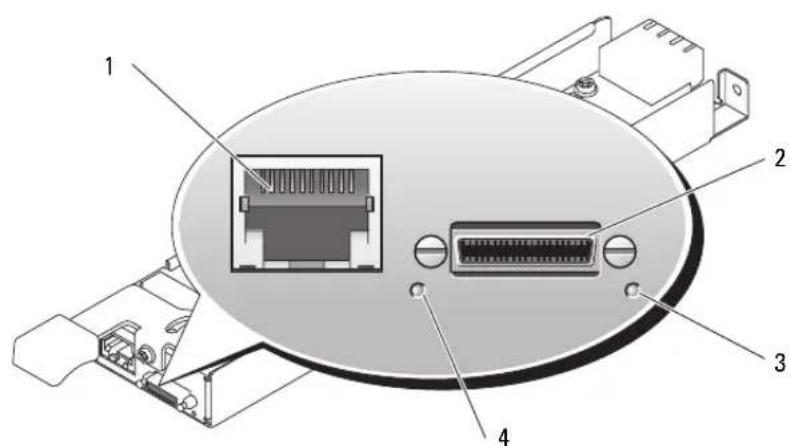
Figure 2-1. Avocent Analog KVM Switch Module
1 ACI port 2 custom connector for custom
3 identification indicator
cable (PS/2 [2] and video)
4 power indicator
The Analog KVM module can be configured using one of the following methods:
-
Connect a local KVM cable (dongle) from the custom connector (see Figure 2-1) to a local KVM and use the OSCAR interface. See "Configuring a KVM Using the OSCAR Interface and Direct Access" on page 35.
-
Connect a CAT 5 cable from the Analog Console Interface (ACI) port (see Figure 2-1) to an external Dell analog or digital KVM switch. See "Configuring a KVM Using the OSCAR Interface and Direct Access" on page 35.
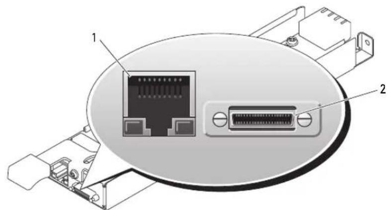
Figure 2-2. Avocent Digital Access KVM Switch Module
1 RJ-45 connector (Ethernet interface) 2 custom connector (for custom KVM cable - PS/2 [2] and video)
The Digital Access KVM module can be configured using one of the following methods:
- (Recommended method) Connect the KVM to the same subnet as the DRAC/MC using the Ethernet connector on the KVM (see Figure 2-2), and use the DRAC/MC interface to configure the KVM. See "Configuring the Avocent Digital Access KVM Module Using the DRAC/MC" on page 43.
- Connect a KVM cable (dongle) from the custom connector (seeFigure 1-3) to a local keyboard, monitor, and mouse. See "Configuring a KVM Using the OSCAR Interface and Direct Access" on page 35.
- Connect a local KVM cable from the custom connector (seeFigure 2-2) to a Server Interface Pod (SIP) and a CAT 5 cable from the SIP to an external Dell Analog or Digital KVM switch. See "Configuring a KVM Using the OSCAR Interface and Direct Access" on page 35.
Configuring a KVM Using the OSCAR Interface and Direct Access
To configure an Analog KVM or Digital Access KVM switch module using direct access through a keyboard, monitor, and mouse, use the On-Screen Configuration and Reporting (OSCAR) graphical user interface.
Running OSCAR
To launch OSCAR, press the

NOTICE: You can also use the

NOTE: To launch OSCAR, you can also press the
Assigning Server Module Names
Use the Names dialog box to identify server modules by unique names rather than by slot number. The Names list is always sorted by slot order.
To access the Names dialog box:
1 Press
2 Click Setup - Names.

NOTE: If new server modules are discovered by the KVM switch system, the on-screen list will be automatically updated. The mouse cursor will change into an hourglass during the update. No mouse or keyboard input will be accepted until the list update is complete.

NOTE: The server module names are stored for each slot on the KVM switch. If a server module is moved, the name does not move with it and must be reassigned in the Names dialog box.
To assign names to server modules:
1 In the Names dialog box, select the name or slot number you wish to change and click Modify.
2 Type a name in the New Name box.
Names of server modules may be up to 15 characters long. Legal characters include: A-Z, a-z, 0-9, space, and hyphen.
3 Click OK to transfer the new name to the Names dialog box.
Your selection is not saved until you click OK in the Names dialog box.
4 Repcat steps 1-3 for each server module in the system.
5 Click OK in the Names dialog box to save your changes.
-Or-
Click X or press <Escape> to exit the dialog box without saving changes.
Viewing and Selecting Slots and Server Modules
You can view your server modules by name or by slot. The slot number is determined by the slot number which a server module occupies. You will see an OSCAR-generated Name list by default when you first launch OSCAR.
To access the Main dialog box:
1 Press
If no password is assigned, the Main dialog box appears.
If a password has been assigned, the Password dialog box appears.Type your password and click OK.
2 The Main dialog box appears.

NOTE: You can also press the
The status of server modules in your system is indicated in the far right column of the Main dialog box. Table 2-1 describes the status symbols.
Table 2-1. OSCAR Status Symbols
| Symbol Description | |
| ○ | Server module is powered on |
| × | Server module is powered off or not installed |
| ← | User connection |
Selecting Server Modules
Use the Main dialog box to select server modules. When you select a server module, the KVM switch reconfigures the keyboard and mouse to the proper settings for that server module.
To select server modules:
- Double-click the server module name or slot number.
- Type the slot number and press <Enter> .
- If the display order of your server module list is by name ( Name button is depressed), type the first few letters of the name of the server module and press
twice.
Disconnecting the analog user from a server module
Press
Configuring OSCAR for Soft Switching
Soft switching is the ability to switch server modules using a hot key sequence. You can soft switch to a server module by pressing
1 Press
2 Click Setup - Menu.
3 Select Name or Slot for the Display/Sort Key.
4 For Delay Time, type the number of seconds of delay desired before the Main dialog box is displayed after
5 Click OK.
To soft switch to a server module:
1 To select a server module, press
2 If the display order of your server module list is by name as chosen above in step 3 (Name button is depressed), type the first few characters of the name of the server module and press
Scanning Your System
In scan mode, the KVM switch automatically scans from slot to slot (server module to server module). You can scan up to 10 server modules by specifying which server modules you want to scan and the number of seconds that each server module will display.
To add server modules to the Scan list:
1 If OSCAR is not open, press
2 Click Setup - Scan.
3 The dialog box contains a listing of all the server modules attached to your unit.
Click to enable the check box next to the server modules you wish to scan.
-or-
Double-click on a server module's name or slot.
-or-
Press <Alt>+ the number of the server module you wish to scan. You can select up to 10 server modules.
4 In the Scan Time box, type the number of seconds (from 3 to 99) of desired time before the scan moves to the next server module in the sequence.
5 Click OK.
To remove a server module from the Scan list:
1 In the Scan dialog box, click to disable the check box next to a server module to be removed. -or- Double-click on a server module's name or slot. -or- Click the Clear button to remove all server modules from the Scan list.
2 Click OK.
To start the scan mode:
1 Press < Print Screenshot>.
2 Click Commands.
3 Select Scan Enable in the Command dialog box.
To cancel scan mode:
1 Select a server module if OSCAR is open. -or- Move the mouse or press any key on the keyboard if OSCAR is not open. Scanning will stop at the currently selected server module. -or- Press
2 Click Commands.
3 ClearScan Enable.
Changing the Display Behavior
Use the Menu dialog box to change the display order of server modules and set a screen delay time for OSCAR.
To access the Menu dialog box:
1 Press
2 Click Setup - Menu.
To choose the display order of server modules in the Main dialog box:
1 Select Name to display server modules alphabetically by name. -or- Select Slot to display server modules numerically by slot number.
2 Click OK.
To set a screen delay time for OSCAR:
1 Type in the number of seconds (0-9) you want to delay display of OSCAR after you press
2 Click OK.
Setting a time to delay display of OSCAR allows you to complete a soft switch without OSCAR displaying. To perform a soft switch, see "Configuring OSCAR for Soft Switching."
Controlling the Status Flag
The status flag displays on your desktop and shows the name of the selected server module or the status of a slot. Use the Flag dialog box to configure the flag to display by server module name, or to change the flag color, opacity, display time, and location on the desktop.
To access the Flag dialog box:
1 Precss
2 Click Setup - Flag.
Displaying Version Information
Use the Version dialog box to display the KVM switch firmware, hardware and FPGA versions, and to identify the language and keyboard configuration. For optimum performance, keep your firmware current.
To display version information:
1 Press
2 Click Commands - Display Versions.
3 The top half of the Version box lists the subsystem versions in the KVM switch.
4 Click X or press <Escape> to close the Version dialog box.
Setting Console Security
OSCAR enables you to set security on your KVM switch console. You can establish a screen saver mode that engages after your console remains unused for a specified delay time. Once engaged, your console will remain locked until you press any key or move the mouse. You will then need to type in your password to continue.
Use the Security dialog box to lock your console with password protection, set or change your password, and enable the screen saver.
To access theSecurity dialog box:
1 Press
2 Click Setup - Security.
To set or change the password:
1 Single-click and press <Enter> or double-click in the New text box.
2 Type the new password in the New text box and press
3 In the Repeat box, type the password again and press
4 Click OK if you only want to change your password, and then close the dialog box.
To password protect your console:
1 Set your password as described in the previous procedure.
2 Select Enable Screen Saver.
3 Type the number of minutes for Inactivity Time (from 1 to 99) to delay activation of password protection and the screen saver feature.
CAUTION: Monitor damage can result if you use Energy mode with monitors not compliant with ENERGY STAR.
4 For Mode, select Energy if your monitor is ENERGY STAR compliant; otherwise select Screen.
5 (Optional) Click Test to activate the screen saver test which lasts 10 seconds then returns you to the Security dialog box.
6 Click OK.
To log in to your console:
1 Press
2 Type your password and then click OK.
3 The Main dialog box appears if the password was entered properly.
To automatically log out of a server module when inactive:
1 In the Main dialog box, click Setup - Security.
2 Type your password, and then click OK. The Security dialog box appears.
3 In the Inactivity Time text box, enter the length of time you want to stay connected to a server module before it automatically disengages you.
4 Click OK.
To remove password protection from your console:
1 In the Main dialog box, click Setup - Security.
2 Type your password, and then click OK.
3 In the Security dialog box, single-click and press
4 Single-click and press
5 Click OK if you only want to eliminate your password.
To enable the screen saver mode with no password protection:
1 If your console does not require a password to gain access to the Security dialog box go to step 2. - or - If your console is password protected, see the previous procedure, then go to step 2.
2 Select Enable Screen Saver.
3 Type the number of minutes for delay time (from 1 to 99) that you want to delay activation of the screen saver.

CAUTION: Monitor damage can result from the use of Energy mode with monitors not compliant with ENERGY STAR.
4 Choose Energy if your monitor is ENERGY STAR compliant; otherwise select Screen.
5 (Optional) Click Test to activate the screen saver test which lasts 10 seconds then returns you to the Security dialog box.
6 Click OK.

NOTE: Activation of the screen saver mode disconnects the server module.
To exit the screen saver mode:
Press any key or move your mouse.
To turn off the screen saver:
1 In the Security dialog box, clear Enable Screen Saver.
2 Click OK.
To immediately turn on the screen saver:
Press < Print Screen>,then press < Pausc>

NOTE: Enable Screen Saver must be selected in the Security dialog box.
OSCAR Navigation Summary
Table 2-2 lists the various keystrokes and mouse functions used by the OSCAR interface.
Table 2-2. Keyboard and Mouse Navigation
| Keystroke Function | |
| Print Screen | • Press once to open OSCAR. • Press twice to send the <Print Screen> keystroke to the currently selected device. |
| NOTICE: You can also use the <Print Screen> key to switch between server modules ("soft switching") by pressing <Print Screen> and then typing the first few characters of its name or number. If you have a Delay Time set and you press the key sequences before that time has elapsed, OSCAR will not display. See "Configuring OSCAR for Soft Switching" on page 37. | |
| F1 Opens the Help screen for the current dialog box. | |
| Escape Closes the current dialog box without saving changes and returns to the previous one. In the Main dialog box, it closes OSCAR and returns to the selected server module. In a message box, it closes the pop-up box and returns to the current dialog box. | |
| Alt | Opens dialog boxes, selects or checks options, and executes actions when used in combination with underlined letters or other designated characters. |
| Alt+X Closes current dialog box and returns to the previous one. | |
| Alt+O | Selects the OK button, then returns to the previous dialog box. |
| Enter | Completes the switch operation in the Main dialog box and exits OSCAR. |
| Single-click Enter | In a text box, selects the text for editing and enables the left-arrow key and right-arrow key keys to move the cursor. Press <Enter> again to quit the edit mode. |
| Up/Down Arrows Moves the cursor from line to line in lists. | |
| Right/Left Arrows | When editing a text box, these keys move the cursor within the column. |
| Home/End | Moves the cursor to the top or bottom of a list. |
| Backspace Erases characters in a text box. | |
| Delete | Deletes characters in a text box. |
| Numbers | Type from the keyboard or keypad. |
| Caps Lock | Disabled. Use the <Shift> key to change case. |
Configuring and Using the Avocent Digital Access KVM Module
The Avocent Digital Access KVM switch module allows you to manage server modules and virtual media from a remote location.
Configuring the Avocent Digital Access KVM Module Using the DRAC/MC
1 Open a supported Web browser.
See "Supported Web Browsers" on page 13.
2 In the Address field, type the IP address of the DRAC/MC that is connected to the Avocent Digital Access KVM Module, and then press
3 In the Logon box, type your user name and password, and then click OK.

NOTE: The default user name is root; the default password is calvin.
4 Turn on the system containing the KVM module. Ensure that the system power indicator is green before proceeding to step 5.
5 Click the Configuration tab and select Network.
6 Use the Network Configuration page to configure the Avocent Digital Access KVM module's NIC settings. Table 2-3 describes each NIC setting.

NOTE: To ensure proper communications between the Avocent Digital Access KVM Module and the DRAC/MC, configure your Avocent Digital Access KVM Module's IP address in the same subnet as the DRAC/MC.

NOTE: To change any of the settings on the Network Configuration page, you must have Configure DRAC/MC permission.
Table 2-3. KVM NIC Settings
| Setting Description | |
| MAC Address Displays the KVM MAC address. | |
| Use DHCP (For NIC IP Address) (Default: Off) | Causes Dell OpenManageTM to obtain the IP address for the Avocent Digital Access KVM NIC from the DHCP server; deactivates the Static IP Address, Static Subnet Mask, and Static Gateway controls. |
| Static IP Address | Specifies or edits the Static IP address for the Avocent Digital Access KVM module NIC. This option is not available if Use DHCP is selected. NOTE: The Avocent Digital Access KVM module default IP address is 192.168.0.121. |
| Static Gateway | Specifies or edits the static gateway for the Avocent Digital Access KVM NIC. This option is not available if Use DHCP is selected. |
| Static Subnet Mask | Specifies or edits the static subnet mask for the Avocent Digital Access KVM NIC. This option is not available if Use DHCP is selected. |
| Auto Negotiation | Determines whether the DRAC/MC automatically sets the Duplex Mode and Network Speed by communicating with the nearest router or hub (On) or allows you to set the Duplex Mode and Network Speed manually (Off). |
| Duplex Mode | Enables you to set the duplex mode to full or half to match your network environment. This option is not available if Auto Negotiation is set to On. |
| Network Speed | Enables you to set the network speed to 100 Mb or 10 Mb to match your network environment. This option is not available if Auto Negotiation is set to On. |
Using the Video Viewer
Using the Video Viewer, you can view and manage server modules remotely as easily as if you were physically present. Using the Virtual Media dialog box, you can manage virtual media sessions allowing you to remotely back up server modules, perform recovery operations, and manage operating system installation to name a few examples.
1 From a web browser, Type https://
NOTE: The DRAC/MC default IP address is 192.168.0.120.
2 Click on DRAC/MC on the left side of the DRAC interface to open the menu beneath it.
3 Open the Video Viewer (by selecting Console).
4 From the list of servers, select the server module (blade) you would like to view.
NOTE: You can also use the
5 Click the Launch Viewer Application button. The server module's desktop will appear.
Once you have connected to a server module, you will see its desktop on your screen. This desktop opens in a separate window where you will see two cursors: your client's cursor and the remote server's cursor, which you will also control through your local mouse. From this window, you will be able to access all the normal functions of this server module as if you were physically present.
Aligning Mouse Cursor
The mouse acceleration speed on the server module may not synchronize with the mouse pointer on your management station, causing two cursors to appear in the Viewer Application window. The procedure varies depending on the server module's operating system. See "Synchronizing the Mouse Pointers" in the Dell Remote Access Controller/Modular Chassis User's Guide for specific instructions for various supported operating systems.
Adjusting the Video Quality
The Viewer Application provides video adjustments that allow you to optimize the video for the best possible view.
To adjust the video quality, perform the following steps:
1 At the bottom of the Viewer Application window, click Calibrate.
2 To adjust the video quality automatically, click the Automatic Video Adjustment button.
3 To manually adjust or fine tune the video quality, including the screen position, click each video adjustment button in the window and adjust the controls as needed.

NOTE: The recommended server module video resolution for optimal console redirection performance is 1024 by 768 pixels and 60Hz refresh rate.

NOTE: Reducing the Pixel Noise Ratio setting to zero causes multiple video refresh commands that generates excessive network traffic and flickering video. You should adjust the Pixel Noise Ratio setting to a level that provides optimal video quality while minimizing network traffic.

NOTE: If the display quality on the console redirection viewer is degraded due to loss of video synchronization, click Refresh in the viewer application.
Using Virtual Media

NOTE: You must install the Java plug-in 1.4.2 or later (1.4.x) to use the Virtual Media feature. To install the Sun java plug-in, go to http://java.sun.com, download JRE 1.4.2 or later (1.4.x), and follow the instructions on screen.
Virtual Media Dialog Box
The Virtual Media dialog box allows you to connect a diskette device, a USB device, CD or DVD device to a target server.
You can select one CD Drive device and one Mass Storage Device at the same time.
- CD Drive options include a CD drive, DVD drive, or a single ISO image file on the drive.
- Virtual Mass Storage Device options include a diskette drive, a USB key or other removable USB storage device, and an ISO image file on the device.
When you have connected a device, you will be able to see it from the remote console through the video viewer. You may then operate the device normally through the video viewer session. (See "Using the Video Viewer"). The device will behave as if it is physically attached to that server.
1 Type https://

NOTE: The DRAC/MC default IP address is 192.168.0.120.
2 Click on DRAC/MC on the left side of the DRAC interface to open the menu beneath it.
3 To access a server from the list of servers, click the button that represents the server you would like to view.
If you are already connected to another server, first disconnect from that server by clicking Detach at the bottom of the display.
4 Click the Attach button at the bottom of the display.
When the system has successfully made the selection, the Launch Media Application button will become active.
5 Select Launch Media Application.
The virtual media dialog box will appear.
NOTE: A valid media should be present in the floppy or CD/DVD drive before the respective virtual media device can be connected.
6 In the Floppy Drive box or the CD/DVD Drive box, select the virtual media that you want to connect to the virtual media device.
7 Click Browse and select the appropriate drive.
8 Click Connect.
Viewing the Connected Device Status
The Virtual Media panel lists the generic mass storage and CD/DVD devices that are currently connected. For each connected device, the target drive, where the target drive is connected and the number of bytes read (for that device) are displayed.
Operating the Device Remotely
Once the device has been connected, operate it remotely through the video viewer by selecting the Console option from the DRAC/MC menu. See "Using the Video Viewer."
Booting to Virtual Media
To boot to a Virtual Media device such as a CD/DVD device, you may need to change the Boot Sequence option using the System Setup program. See "Using the System Setup Program" in your Hardware Owner's Manual for information on changing the boot order.
Installing Operating Systems Using Virtual Media
1 Ensure that the operating system installation CD is inserted in the management station's CD drive.
2 Ensure that you have selected your local CD drive and that you have connected to the virtual drives.
3 Follow the steps for booting from the virtual media in the preceding section to ensure that the BIOS is set to boot from the CD drive that you are installing from.
4 Follow the instructions on the screen to complete the installation.
Using Virtual Media When the Server's Operating System is Running
- On a server using the Microsoft Windows operating system, the virtual media drives are mounted and given a drive letter.
Using the virtual drives from within Windows is similar to using your physical drives. When you connect to the media at a management station, the media is available at the system by simply clicking the drive and browsing its content.
- On a server using the Red Hat Enterprise Linux or SUSE Linux Enterprise Server operating system, the virtual drives must be mounted before the drives can be accessed. Before mounting the drive, first connect to the media at the management station.
Red Hat Enterprise Linux automatically creates mount points in the /etc/fstab file for the virtual floppy and CD drives.
Type the following command to quickly identify the assigned virtual media devices:
cat /var/log/messages | grep Virtual
Updating the KVM Firmware
Use one of the following methods to update your KVM firmware.
- Wcb-based interfaccs
- RACADM CLI
Using the DRAC/MC Web-based Interface to Update the KVM Firmware

NOTE: You can download a TFTP server from http://solarwinds.net. For information on installing and configuring the SolarWinds TFTP server, refer to the SolarWinds website.
1 Copy the KVM firmware binary file to a TFTP server root directory.
2 Log on to the DRAC/MC Web-based user interface using a supported Internet browser. See "Supported Web Browsers" on page 13.
3 Select KVM Update for the module to be updated.
4 From the DRAC/MC Web-based user interface main window, click the Update tab. The Firmware Update window is displayed.
5 On the Firmware Update window, enter the IP address of the TFTP server and the KVM firmware image name and select the KVM firmware as the option to update.

NOTE: The Digital KVM firmware image name length is limited to 20 characters.
6 Click Update Firmware.
7 The TFTP download and firmware update process may take several minutes. After the update completes, the KVM resets.
Using the RACADM Command Line Interface to Update the KVM Firmware
NOTE: You can download a TFTP server from http://solarwinds.net. For information on installing and configuring the SolarWinds TFTP server, refer to the SolarWinds website.
1 Copy the KVM firmware binary file to a TFTP server root directory.
2 Log on to the DRAC/MC Telnet or serial interface. See "Serial or Telnet Console Interface" on page 14
3 Enter the racadm fwupdate command, as in the following example:
racadm fwupdate -a
4 The TFTP download and firmware update process may take several minutes. After the update completes, the KVM resets.
racadm chassisaction -m chassis powerup

console# show version
switch-1# line vty 0 15
Redirection After Boot-Enabled

racadm chassisaction -m chassis powerup
console# show version
switch-1# line vty 0 15
racadm chassisaction -m chassis powerup

console# show version
- Notes, Notices, and Cautions
- Contents
- General System Configuration. 5
- Connecting a USB Drive, Keyboard, and Mouse to the Server Module Front Panel 10
- Configuring the DRAC/MC Module 11
- Integrating the System Into the Network 22
- Configuring the Cisco Catalyst Blade Switch 3030 29
- Gb Pass-through Module 31
- Enabling PXE on a Gb Ethernet Daughter Card 31
- Configuring the KVM Switch Module 33
- Configuring a KVM Using the OSCAR Interface and Direct Access 35
- Configuring and Using the Avocent Digital Access KVM Module 43
- Updating the KVM Firmware. 47
- General System Configuration
- Other Documents You May Need
- Initial Setup
- Configuring Drive Mirroring
- Additional Integrated Mirroring Guidelines
- Connecting a USB Drive, Keyboard, and Mouse to the Server Module Front Panel
- Installing an Operating System
- Configuring the DRAC/MC Module
- DRAC/MC Module Features
- DRAC/MC Configuration Interface Options
- Web-Based Interface
- Supported Web Browsers
- Accessing the DRAC/MC Web-Based Interface
- Serial or Telnet Console Interface
- Configuring the System Setup Program on the Server Module
- Connecting to the DRAC/MC Using Minicom for Serial Console Emulation (Red Hat Enterprise Linux and SUSE Linux Enterprise Server)
- Connecting to the DRAC/MC Using HyperTerminal for Serial Console Redirection (Windows Operating System)
- Connecting to the DRAC/MC Using XTerm for Telnet Console Redirection (Red Hat Enterprise Linux and SUSE Linux Enterprise Server)
- Connecting to the DRAC/MC Using Microsoft Telnet for Telnet Console Redirection
- Using a Serial or Telnet Console
- Redirecting the DRAC/MC Serial Console to the Ethernet Switch Module
- Updating the DRAC/MC Module Firmware
- Using the DRAC/MC Web-based Firmware Update Interface
- Using the RACADM CLI to Update the DRAC/MC Firmware
- Clearing the Web Browser Cache
- Clearing the Web Browser Cache With Internet Explorer
- Clearing the Web Browser Cache With Mozilla or Firefox
- Using the Firmware Recovery Console
- Integrating the System Into the Network
- Configuring a Port on a Dell PowerConnect 5316M Ethernet Switch Module
- Configuring a Port on a Cisco Catalyst Blade Switch 3030 Switch Module
- Configuring the PowerConnect 5316M Ethernet Switch Module
- Updating the PowerConnect Switch Module Firmware
- System Image Download
- Configuring the Cisco Catalyst Blade Switch 3030
- Configuring the Cisco Switch Using a Web Browser and a Management Station
- Configuring the Switch Using a Serial or Telnet Console
- Gb Pass-through Module
- Gb Pass-through Module Link Negotiations
- Enabling PXE on a Gb Ethernet Daughter Card
- Enabling PXE on the Broadcom TOE NIC Daughter Card
- Configuring the KVM Switch Module
- Configuring a KVM Using the OSCAR Interface and Direct Access
- Running OSCAR
- Assigning Server Module Names
- Viewing and Selecting Slots and Server Modules
- Selecting Server Modules
- Disconnecting the analog user from a server module
- Configuring OSCAR for Soft Switching
- Scanning Your System
- Changing the Display Behavior
- Controlling the Status Flag
- Displaying Version Information
- Setting Console Security
- CAUTION: Monitor damage can result if you use Energy mode with monitors not compliant with ENERGY STAR.
- CAUTION: Monitor damage can result from the use of Energy mode with monitors not compliant with ENERGY STAR.
- NOTE: Activation of the screen saver mode disconnects the server module.
- NOTE: Enable Screen Saver must be selected in the Security dialog box.
- OSCAR Navigation Summary
- Configuring and Using the Avocent Digital Access KVM Module
- Configuring the Avocent Digital Access KVM Module Using the DRAC/MC
- Using the Video Viewer
- Aligning Mouse Cursor
- Adjusting the Video Quality
- Using Virtual Media
- Virtual Media Dialog Box
- Viewing the Connected Device Status
- Operating the Device Remotely
- Booting to Virtual Media
- Installing Operating Systems Using Virtual Media
- Using Virtual Media When the Server's Operating System is Running
- Updating the KVM Firmware
- Using the DRAC/MC Web-based Interface to Update the KVM Firmware
- Using the RACADM Command Line Interface to Update the KVM Firmware
Brand : DELL
Model : PowerEdge 1955
Category : Server