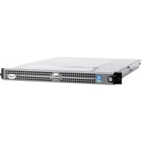
PowerEdge 1750 - Server DELL - Free user manual and instructions
Find the device manual for free PowerEdge 1750 DELL in PDF.




User questions about PowerEdge 1750 DELL
0 question about this device. Answer the ones you know or ask your own.
Ask a new question about this device
Download the instructions for your Server in PDF format for free! Find your manual PowerEdge 1750 - DELL and take your electronic device back in hand. On this page are published all the documents necessary for the use of your device. PowerEdge 1750 by DELL.
USER MANUAL PowerEdge 1750 DELL
Installing or Replacing an ERA/O Card
安装或更换 ERA/0 卡
Installing or Replacing an ERA/O Card
Notes, Notices, and Cautions

NOTE: A NOTE indicates important information that helps you make better use of your computer.

NOTICE: A NOTICE indicates either potential damage to hardware or loss of data and tells you how to avoid the problem.

CAUTION: A CAUTION indicates a potential for property damage, personal injury, or death.
Information in this document is subject to change without notice. © 2003 Dell Computer Corporation. All rights reserved.
Reproduction in any manner whatsoever without the written permission of Dell Computer Corporation is strictly forbidden.
Trademarks used in this text: Dell, PowerEdge, and the DELL logo are trademarks of Dell Computer Corporation.
Other trademarks and trade names may be used in this document to refer to either the entities claiming the marks and names or their products. Dell Computer Corporation disclaims any proprietary interest in trademarks and trade names other than its own.
February 2003 P/N K0238 Rev. A00
This document explains how to install and remove your system's Embedded Remote Access Option (ERA/O) card.
Before You Begin
NOTE: For more information about setting up and using an ERA/O card, see the remote access controller (RAC) documentation provided on the documentation CD that came with your system or on the Dell Support website at support.dell.com.
NOTE: The Dell™ Remote Access Card III (DRAC III), DRAC III/XT, Embedded Remote Access (ERA), and the ERA/O are systems management hardware and software solutions designed to provide remote management capabilities for PowerEdge™ systems. Collectively, these solutions are known as remote access controllers (RACs). RACs allow you to remotely manage and monitor your system even when the system is down.
Before installing the ERA/O card, record the system configuration settings. View the system configuration screens in the System Setup program and make a note of each setting. See your User's Guide for instructions about using the System Setup program.
Installing an ERA/O Card
CAUTION: Only trained service technicians are authorized to remove the system cover and access any of the components inside the system. See your System Information Guide for complete information about safety precautions, working inside the computer, and protecting against electrostatic discharge.
1 Remove the optional front bezel (if applicable).
2 Turn off the system, including attached peripherals, and disconnect the system and peripherals from their electrical outlets.
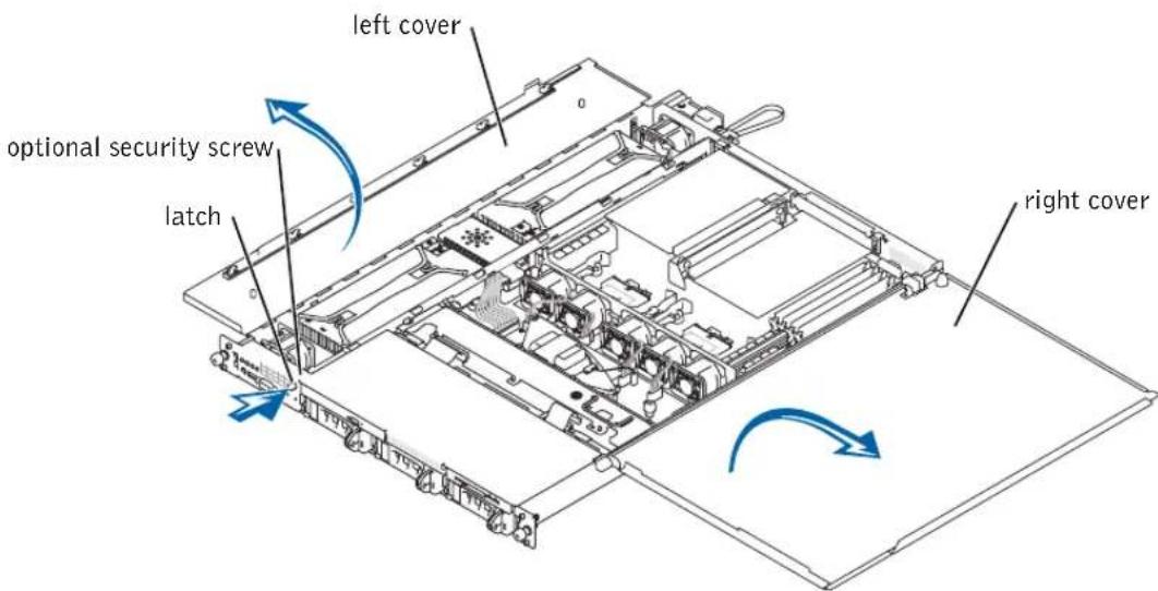
3 Remove the optional security screw (if applicable). See Figure 1-1.
4 Press the latch on the system front panel and lift the left cover.
5 Lift the right cover.
Figure 1-1. Opening the System Covers
text_image
left cover optional security screw latch right cover6 Remove the SCSI backplane board:
a Pull each hard-drive carrier partially out of its slot, approximately 2.5 cm (1 inch).
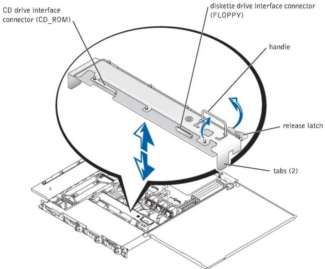
b Disconnect the diskette-drive interface cable from the FLOPPY connector on the backplane board. See Figure 1-2.
c Disconnect the CD drive interface cable from the CD_ROM connector on the backplane board. See Figure 1-2.
d Press the release latch in toward the backplane board and use the handle to pull the board out of its connector and up out of the chassis. See Figure 1-2.
Figure 1-2. SCSI Backplane Board
text_image
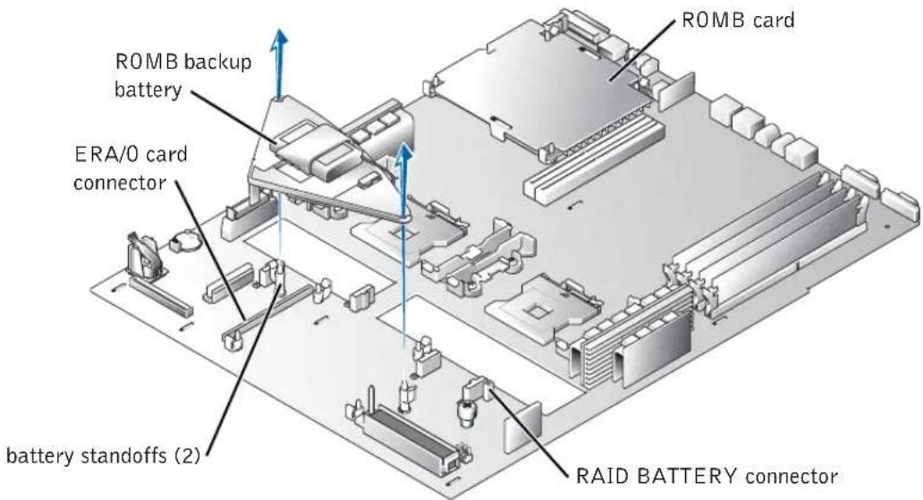
CD drive interface connector (CD_ROM) diskette drive interface connector (FLOPPY) handle release latch tabs (2)7 If the system has an optional ROMB card installed, remove the ROMB backup battery (not the ROMB card itself) to expose the ERA/O card connector.
See Figure 1-3; see also "Removing a ROMB Card" in your Installation and Troubleshooting Guide.
8 Unpack the ERA/O card.
If you are replacing an ERA/O card, see "Removing an ERA/O Card" for removal instructions before continuing with the next step.
Figure 1-3. Removing the ROMB Backup Battery
text_image
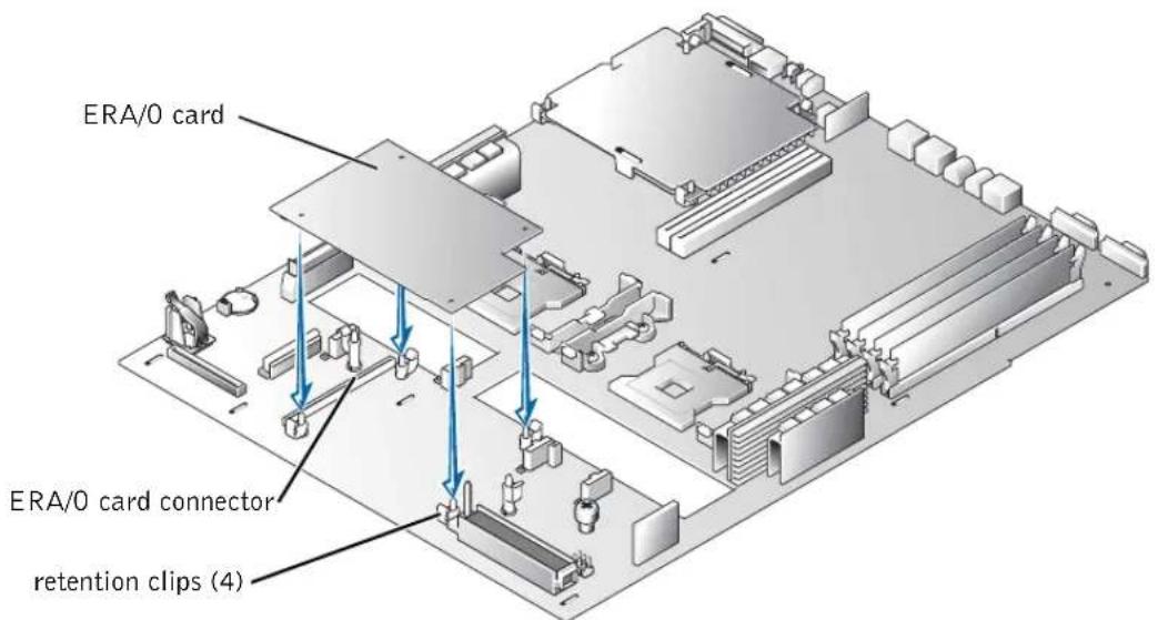
ROMB card ROMB backup battery ERA/0 card connector battery standoffs (2) RAID BATTERY connector9 Install the ERA/O card in the ERA/O card connector (EMBEDDED_REMOTE_ASSISTANT) on the system board. See Figure 1-4.
a Align the connector on the bottom of the ERA/O card with the ERA/O connector on the system board; align the holes along the edges of the card with the center posts of the four retention clips on the system board.
b Press the card down into the connector and onto the retention clip posts until the clips snap into place around the card and the card is fully seated into the connector.
Figure 1-4. Installing the ERA/O Card
text_image
ERA/0 card ERA/0 card connector retention clips (4)10 If you removed a ROMB backup battery in step 7, replace the battery. See Figure 1-3; also see "Installing a ROMB Card" in your Installation and Troubleshooting Guide.
11 Replace the SCSI backplane. See Figure 1-2.
a Fit the metal tabs at each end of the backplane into the slots in the chassis wall, and lower the backplane into the chassis, ensuring that the CD and diskette drive interface cables are not caught under the backplane.
b Press down firmly over the handle to seat the backplane in its connector.
c Pivot the release latch out into the securing slot in the chassis.
d Connect the CD drive interface cable to the CD_ROM connector on the backplane board.
e Connect the diskette-drive interface cable to the FLOPPY connector on the backplane board.
f Press all installed hard drives firmly back into the SCSI connectors on the backplane.
12 Close the system covers.
When closing the covers, close the right (larger) cover first and then close the left cover. Press firmly on the left cover to snap the securing latch into place.
13 Install the optional security screw (if applicable). See Figure 1-1.
14 Reconnect the system and peripherals to their electrical outlets, and turn them on.
15 Install the optional front bezel (if applicable).
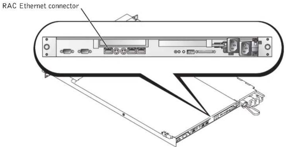
16 If the 100-Mbps RAC Ethernet connector on the back of the system has not been used before, you must remove the thin plastic cover that protects the connector.
You can insert your finger underneath the silver strip at the top of the cover to tear away the cover. See Figure 1-5 for the location of the connector.
17 Connect a network cable to the RAC Ethernet connector. See Figure 1-5.
Figure 1-5. RAC Ethernet Connector
text_image
RAC Ethernet connector18 Update the ERA/O card with the latest version of the ERA/O firmware, available at the Dell Support website at support.dell.com.
See the RAC documentation provided on the documentation CD for information about updating the firmware.
Removing an ERA/O Card

CAUTION: Only trained service technicians are authorized to remove the system cover and access any of the components inside the system. See your System Information Guide for complete information about safety precautions, working inside the computer, and protecting against electrostatic discharge.
1 Perform steps 1–7 in "Installing an ERA/O Card."
2 Push open the two retention clips nearest the ERA/O card connector while lifting that end of the card from the connector. See Figure 1-4.
3 Push open the remaining two retention clips and remove the card completely.
4 Perform steps 10–15 in "Installing an ERA/O Card."
5 Disconnect the network cable from the RAC Ethernet connector (if applicable). See Figure 1-5.
Dell™ 系统
安装或更换 ERA/0 卡
注注意和警告
text_image
conector RAC EthernetPrinted in the U.S.A.
趙稸盍変
Printed on recycled paper
中国印制
Imprimé en Chine
Gedruckt in China
중국에서 인쇄
Impreso en China
0K0238A00
P/N K0238 Rev. A00
Printed in Ireland
爱尔兰印制
Imprimé en Ireland
Gedruckt in Ireland
아일랜드에서 인쇄
Impreso en Ireland
0K0238A00
P/N K0238 Rev. A00