
NP01SW1 - Hi-fi system NEC - Free user manual and instructions
Find the device manual for free NP01SW1 NEC in PDF.
| Product Type | Projector/Screen Interface Selector |
| Brand | NEC |
| Model | NP01SW1 |
| Dimensions (W × H × D) | 285 × 64 × 187 mm (11.2 × 2.5 × 7.4 inches) |
| Weight | 1.4 kg (3.1 lbs) |
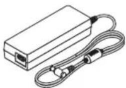
| Power Supply | 19.5 V DC via power adapter (AD1930, included) |
| Power Consumption | 21 W (AC), 0.1 W standby |
| Video Inputs | 3 × HDMI (Type A), including 1 MHL compatible |
| Video Output | 1 × HDBaseT (RJ-45), up to 100 m (70 m for 4K) |
| Audio Input | 1 × Mono mini-jack (microphone) |
| USB Ports | 1 × USB-A, 1 × USB-B |
| LAN Port | 1 × RJ-45 (10/100 BASE-TX, non-PoE) |
| Infrared Sensor | Yes (built into the selector) |
| Main Functions | HDMI switching, projector control, audio mute, volume, microphone, HDCP/3D/4K support |
| SETUP Button | Press once after initial installation to save connections |
| Included Accessories | Power adapter, power cords (×2), mounting units, screws |
| Operating Temperature | 5 °C to 40 °C |
| Operating Humidity | 20% to 80% (non-condensing) |
| Storage Temperature | -10 °C to 50 °C |
| Safety | Do not open the housing, use only the supplied adapter, avoid moisture |
| Maintenance | Clean with a dry cloth; do not use solvents |
| Repairability | Do not repair yourself; contact the dealer |
Frequently Asked Questions - NP01SW1 NEC
User questions about NP01SW1 NEC
0 question about this device. Answer the ones you know or ask your own.
Ask a new question about this device
Download the instructions for your Hi-fi system in PDF format for free! Find your manual NP01SW1 - NEC and take your electronic device back in hand. On this page are published all the documents necessary for the use of your device. NP01SW1 by NEC.
USER MANUAL NP01SW1 NEC
Safety requirement in Singapore:
Main Plug:
-Use 3 pin mains plug that is registered with Singapore Safety Authority.
-Use 2 pin mains plug that is complied with EN50075.
Flexible cord:
-Use double insulated flexible cord that is certified* to the relevant IEC Standards.
Appliance connector:
-Use an appliance connector certified* IEC320.
* certified by member of IECEE CB Scheme.
Interface selector
NP01SW series (NP01SW1/NP01SW2)
Installation Manual
Contents
Introduction ......ENG-2
Read This Before Starting ......ENG-4
- Packaged Items ......ENG-7
- Part Names ......ENG-8
2-1. Interface selector ......ENG-8
2-2. Receiver box (included with the NP01SW2) ......ENG-12
3.Mounting the interface selector on a wall ......ENG-13
3-1. Mounting the interface selector on a wall ......ENG-13
3-2. Mounting the AC adapter on a wall ......ENG-14
- Mounting the Receiver Box on the Ceiling Mount Unit or on a Wall (for the NP01SW2)....ENG-15
4-1. Fixing the mount unit on the receiver box ......ENG-15
4-2. In case to fix the receiver box on the ceiling mount unit ...ENG-15
4-3. In case to fasten the receiver box on a wall .....ENG-15
- Device Connection Examples ......ENG-16
5-1. Projecting the image of a computer, etc. ......ENG-16
5-2. Using separately sold Interactive White Board Kit for the projector ....ENG-21
5-3. Using built-in Touch Panel display ......ENG-22
5-4. Controlling the projector or display via LAN ......ENG-23
- Specifications ....ENG-24
6-1. Interface selector (common for both the NP01SW1 and NP01SW2) ......ENG-24
6-2. AC adapter(common for both the NP01SW1 and NP01SW2)....ENG-24
6-3. Receiver box (included with the NP01SW2) ......ENG-25
Thank you very much for purchasing the NEC Interface selector NP01SW series (NP01SW1/NP01SW2).
This product is equipped with various input terminals and the HDBaseT output terminal.
By utilizing this product, it makes simple to connect several devices with our projector or display in a classroom or a meeting room. The receiver box is supplied with the interface selector for NP01SW2.
- This product equips various input terminals (HDMI (x 3), Mic, LAN, USB-A, USB-B, etc) and the remote control sensor.
- This product equips the HDBaseT output terminal. This able to receive/transmit HDBaseT signal from/to the projector or display which equips the HDBaseT input terminal connecting by a commercially available LAN cable.
* The receiver box is included with NP01SW2, it can be connected with the projector or display not equipped the HDBaseT input terminal.
* HDBaseT is a connection standard for home appliances that is established by the HDBaseT Alliance.
* Use a commercially available LAN cable satisfied the below specifications for connecting to the HDBaseT port.
| Conditions Cable length Cable specifications | ||
| Not connecting to the receiver box | Max. 100m (Max 70m for transmitting 4K signal) | CAT5e or over STP cableRecommended thickness AWG23 |
| Connecting to the receiver box Max. | 30m CAT6A or over STP cable | Recommended thickness AWG23 |
(Note) It may not fulfil its performance depending on a cable.
- The HDMI input terminal and HDBaseT port on this product support HDCP.
- The HDMI3 input terminal supports MHL. It can be connected with the MHL supported smart phone or tablet by using a commercially available MHL cable.
- This product can be connected with the Interactive Whiteboard kit for the NEC projectors.
- For the projectors or displays equipped the slot, it can be input HDBaseT signal by loading the option board, SB-07BC, into the slot and connect with this product by a commercially available LAN cable. (The receiver box is not required.)
- For checking supported projectors and displays, please visit our web site.
NOTE
- Transmittable signals by this product are determined. Please check and set up the output signal from video devices to supported signal in advance. Please refer to Specifications on page ENG-24 and ENG-25.
Disposing of your used product

EU-wide legislation as implemented in each Member State requires that used electrical and electronic products carrying the mark (left) must be disposed of separately from normal household waste. When you dispose of such products, please follow the guidance of your local authority and/or ask the shop where you purchased the product.
After collecting the used products, they are reused and recycled in a proper way. This effort will help us reduce the wastes as well as the negative impact such as mercury contained in parts to the human health and the environment at the minimum level.
The mark on the electrical and electronic products only applies to the current European Union Member States.
IMPORTANT INFORMATION
SETUP Button on this product
- After completion of connection between this product and the projector or display, make sure to press the SETUP button on this product once at the beginning. For more details on the SETUP button, please refer page ENG-9. Please be reminded to perform the following steps 1 to 4 before pressing the SETUP button.
(1) Power on each device connected with this product.
(2) Select input terminal on the projector or display for this product.
(3) Press a terminal button among the input terminal HDMI 1, 2 and 3 from which the image you want to display will be transmitted. Image will be displayed on the projector or display. It does not matter if it's in no signal state.
(4) Press the SETUP button on this product.
While the SETUP operation is processing, all indicators are turned up. When the SETUP operation is completed properly, the indicators are turned off and go back into the previous state. If the SETUP operation is failed to complete, all indicators flushed in 2 cycles and go back into the previous state
- By pressing the SETUP button for the first use, every time pressing one button among HDMI1, 2 and 3 accompanied to switch the image input terminal on the connected projector or display from the next time.
- If the SETUP button is not pressed, the operation buttons may not work properly.
- The terms HDMI and HDMI High-Definition Multimedia Interface, and the HDMI Logo are trademarks or registered trademarks of HDMI Licensing LLC in the United States and other countries.

HIGH-DEFINITION MULTIMEDIA INTERFACE
- HDBaseT™ is a trademark of HDBaseT Alliance.

- MHL, Mobile High-Definition Link and the MHL Logo are trademarks or registered trademarks of the MHL, LLC.

- Other product names and company logos mentioned in this manual may be the trademarks or registered trademarks of their respective holders.
Cautions
(1) Unauthorized reprinting of the contents of this manual is prohibited.
(2) The contents of this manual are subject to change in the future without notice.
(3) The contents of this manual have been prepared with scrupulous care, but please notify NEC should you have any doubts or notice any mistakes or omissions.
(4) Please note that NEC will accept no responsibility whatsoever for claims for damages, lost earnings, etc., arising from the use of this product, regardless of article (3) above.
(5) NEC will replace any manuals presenting incorrect collation or missing pages.
Read This Before Starting
About the pictograms
To ensure safe and proper use of the product, this installation manual uses a number of pictograms to prevent injury to you and others as well as damage to property.
The pictograms and their meanings are described below. Be sure to understand them thoroughly before reading this manual.

WARNING
Failing to heed this pictogram and handling the product erroneously could result in accidents leading to death or major injury.

CAUTION
Failing to heed this pictogram and handling the product erroneously could result in personal injury or damage to surrounding property.
Examples of pictograms
| The symbol indicates instructions urging caution (including warnings).A concrete indication of the caution is given within the symbol. | |
| The symbol indicates prohibited actions.A concrete indication of the prohibited action is given within the symbol. | |
| The symbol indicates required actions.A concrete indication of the required action is given within the symbol. |

WARNING


- Consult your dealer about installation. Do not attempt to install this product by yourself, it may cause of injury.
- Supply power to this product as described in this manual. Improper connections could lead to fire or electric shocks.
- The included AC adapter, AC power cord and cable are exclusive use for this product. Do not use them for other products for safety.
It is essential to connect the included AC adapter with this product. Concerning to the power cord, make sure to use either the included one or double insulated one satisfied requirement on safety standard for each country. If an inappropriate AC Adapter or a power cord is used, it may cause of fire or electric shock. - Do not connect or disconnect cables with wet hands. Doing so could result in electric shocks.
- If this product or the AC adapter should produce smoke, strange sounds or strange odors, or if this product or the AC adapter should be dropped or the cabinet be damaged, unplug this product's power cord from the power outlet. For the receiver box, disconnect all connected cables. Failure to do so could result in electric shocks. After doing the above, contact your dealer for repairs.
- Do not remove or open the cabinet of either this product or the AC adapter. Also, do not try to repair or alter on your own. Doing so could result in fire or electric shocks. For internal inspections, adjustments or repairs, contact your dealer.
- Handle the cables with extreme care. Damaged cables could lead to fire or electric shocks.
- Do not place heavy objects on the cables.
- Do not place projectors or displays on the cables.
- Do not cover the cables with rugs, etc.
- Do not scratch or alter the cables.
- Do not excessively bend, twist or pull on the cables.
- Do not heat the cables.
If a cable is damaged (exposed core wires, broken wires, etc.), contact your dealer.
 | · Do not use in locations subject to humidity or water as the below. At the same time, do not put on a liquid filled container on the top of the product. Failure to do so could result in electric shocks.- Do not use in rain or in snow, on beaches or shores.- Do not use in bathrooms or shower stalls.- Do not place vases or flowerpots on top of the product.- Do not place glasses, cosmetics or chemicals on top of the product.Should foreign objects, water, etc., get inside the product, unplug the power cord immediately. For the receiver box, disconnect all connected cables. After unplugging the power cord, contact your dealer. |
 | · Do not use in the below conditions. Failure to do so could result in electric shocks.- On rickety tables, tilted surfaces or other unstable places.- Near heaters or in places with strong vibrations.- Outdoors or in humid or dusty places.- In places exposed to soot or steam.- Near stove tops or humidifiers. |
 | · If you hear the roll of thunder, do not touch the power plug. Doing so could result in electric shocks. |

CAUTION


- Connect this product's HDBaseT port and LAN port to a network on which there is no risk of overvoltage. Overvoltage applied to the HDBaseT port or LAN port could result in electric shocks.
- This product's LAN port does not support PoE. Connecting this product's LAN port to a network supplying electric power could result in combustion or damage.
- Use in a well-ventilated place. Do not obstruct the receiver box's ventilation holes. Doing so could cause the receiver box to overheat, leading to fire. Provide sufficient space around the product.
Other Cautions
- Can not use for HDBaseT receiver box other than the included one. This product is available exclusively for the included receiver box.
- Use the included HDMI cable and RS-232C cable for connecting the receiver box and display device.
- This product only supports one-on-one connection using the HDBaseT port of the projector, display or receiver box. This product's HDBaseT port does not support connection with multiple devices using a hub, etc.
- Do not route the commercially available LAN cable used for connection between this product and a projector, display or the receiver box's HDBaseT port outdoors.
- Do not install and store this product in the below circumstances. Failure to do so may cause of malfunction.
- In powerful magnetic fields
- In corrosive gas environment
- When moving this product, first disconnect all connected cables. Failure to do so could result in damage.
- Make sure to power off this product before connecting/disconnecting the LAN cable on the this product's HDBaseT port.
Failure to do so could result in damage. - When disposing of the product
When disposing of this product, first consult your store of purchase or local government.
DOC Compliance Notice (for Canada only)
This Class B digital apparatus complies with Canadian ICES-003.
RF Interference (for USA only)
WARNING
The Federal Communications Commission does not allow any modifications or changes to the unit EXCEPT those specified by NEC Display Solutions of America, Inc. in this manual. Failure to comply with this government regulation could void your right to operate this equipment. This equipment has been tested and found to comply with the limits for a Class B digital device, pursuant to Part 15 of the FCC Rules. These limits are designed to provide reasonable protection against harmful interference in a residential installation. This equipment generates, uses, and can radiate radio frequency energy and, if not installed and used in accordance with the instructions, may cause harmful interference to radio communications. However, there is no guarantee that interference will not occur in a particular installation. If this equipment does cause harmful interference to radio or television reception, which can be determined by turning the equipment off and on, the user is encouraged to try to correct the interference by one or more of the following measures:
- Reorient or relocate the receiving antenna.
- Increase the separation between the equipment and receiver.
- Connect the equipment into an outlet on a circuit different from that to which the receiver is connected.
- Consult the dealer or an experienced radio / TV technician for help.
WARNING TO CALIFORNIA RESIDENTS:
Handling the cables supplied with this product will expose you to lead, a chemical known to the State of California to cause birth defects or other reproductive harm. WASH HANDS AFTER HANDLING.
DECLARATION OF CONFORMITY
This device complies with Part 15 of FCC Rules. Operation is subject to the following two conditions. (1) This device may not cause harmful interference, and (2) this device must accept any interference received, including interference that may cause undesired operation.
U.S.Responsible Party: NEC Display Solutions of America, Inc.
Address: 500 Park Boulevard, Suite 1100
Itasca, Illinois 60143-1248
Tel. No.: (630) 467-3000
Type of Product: Interface selector
Equipment Classification: Class B Peripheral
Model No.: NP01SW

We hereby declare that the equipment specified above conforms to the technical standards as specified in the FCC Rules.
1. Packaged Items
Common for both the NP01SW1 and NP01SW2
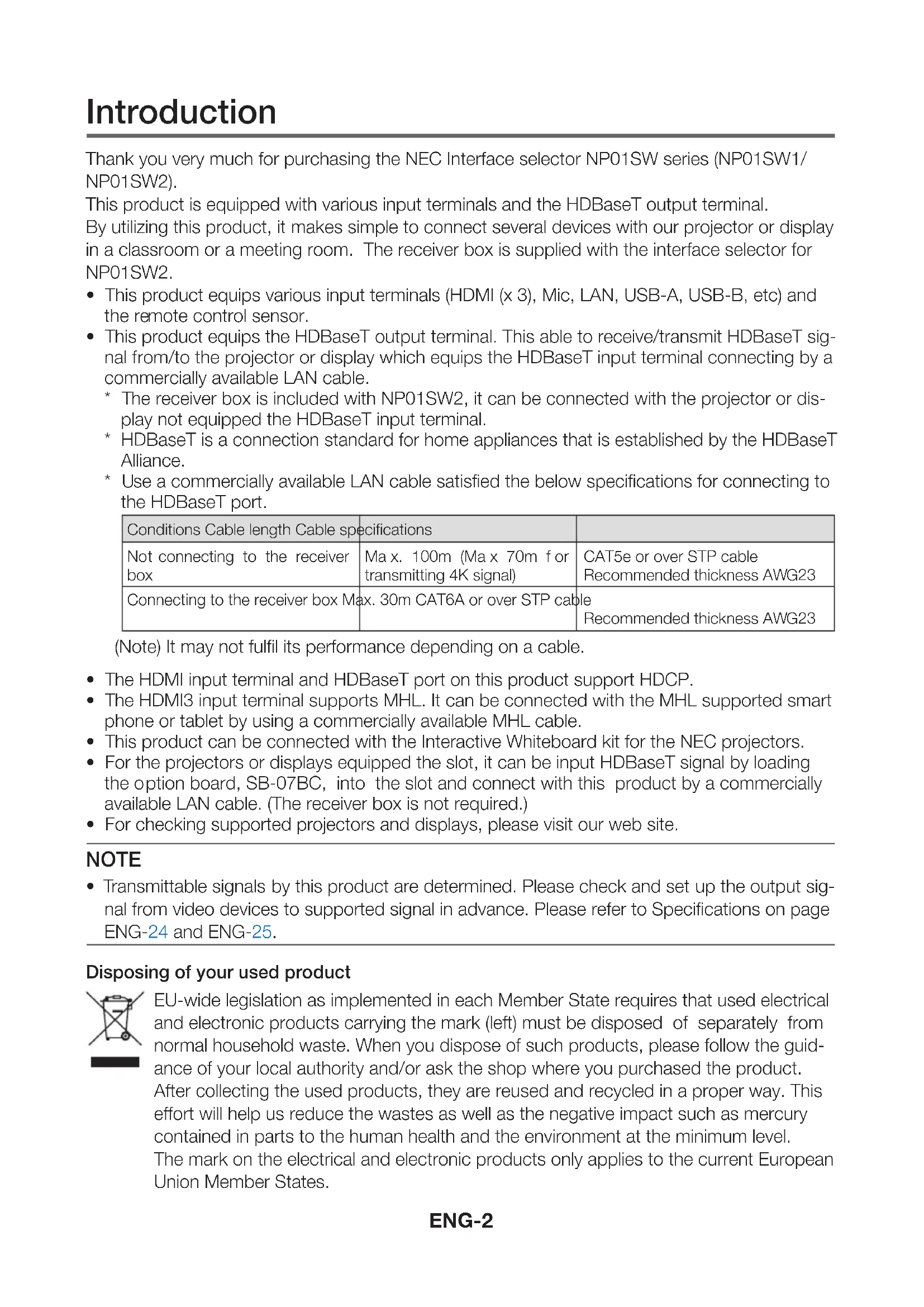
□ Main body of interface selector
natural_image
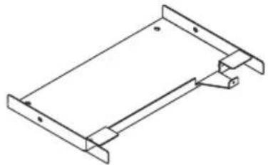
Line drawing of a rectangular electronic device with ports and buttons (no text or symbols)□ AC adapter (3N10206□) 1
□ Mount unit (for main unit: large) (24H8241□) 1

natural_image
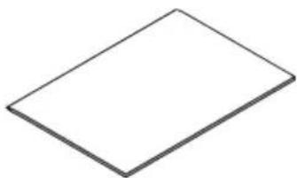
Pure technical line drawing of a mechanical component (no text or symbols)□ Mount unit (for main unit: small) (24H8242□) 1
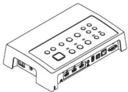
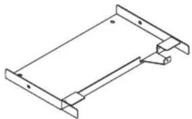
□ Mount unit (for wall)
(24H8240□) 1
natural_image
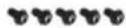
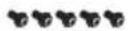
Isometric line drawing of a rectangular metal frame with mounting holes (no text or symbols)□ Mounting screws (M3) 5
natural_image
Line drawing of a rectangular electronic device with a coiled cable and connector (no text or symbols)□ Installation Manual (7N8N673□) (this manual)

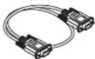
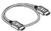
□ Power cord (US:7N080245/EU:7N080031) 2

natural_image
Two identical wire-wrapped electrical connectors with metal contacts and connectors (no text or symbols)□ Mount unit (for AC adapter) (24H8244□) 1
natural_image
Simple geometric shape: a tilted square with no text or symbols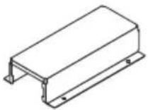
The NP01SW2 additionally includes the following items:
□ Receiver box (NP01R) 1
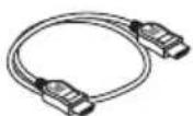
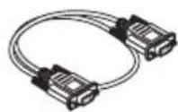
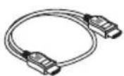
☐ HDMI cable (7N960240) 1
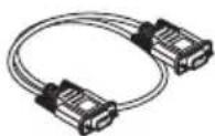
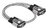
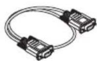
□ RS-232C cable (7N960241) 1
natural_image
Isometric line drawing of a computer internal unit (no text or symbols)□ Mount unit (24H8243□) 1
□ Mounting screw (M3) 1

For your reference
- If any accessories should be missing or damaged, contact your dealer.
- Accessories may appear slightly different from the illustrations in this manual, but this is not a problem in terms of practicality.
2. Part Names
2-1. Interface selector
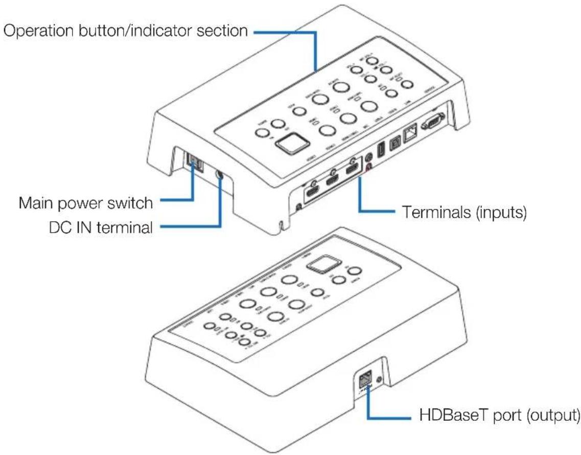
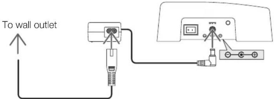
DC IN terminal
Connect the included AC adapter.
Connect the interface selector, AC adapter, power cord and power outlet securely.
Main power switch
Turns the interface selector's power on and off.
Attention:
- Immediate after turning on the main power switch, all indicators for operation buttons flush. While the indicators are flushing, operation buttons become unavailable.
HDBaseT port (output)
Connect a commercially available LAN cable here.
Connect either with the projector/display equipped the HDBaseT port or the receiver box here.
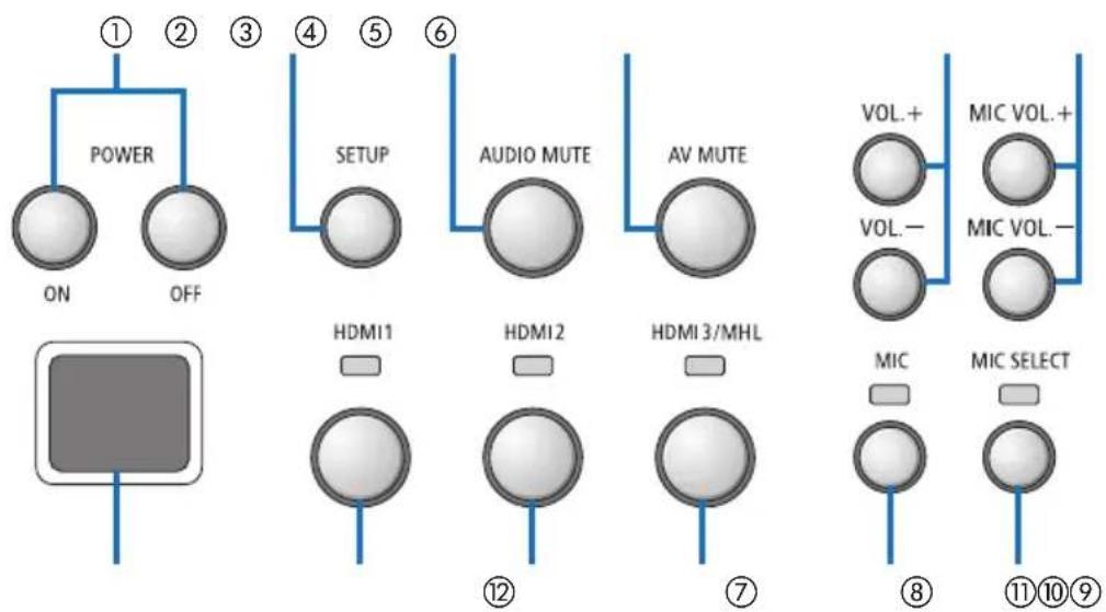
Operation button/indicator section
flowchart
graph TD
    A["POWER ON OFF"] --> B["SETUP"]
    B --> C["AUDIO MUTE"]
    C --> D["AV MUTE"]
    D --> E["VOL+ VOL- MIC VOL. + MIC SELECT"]
    F["HDMI1"] --> G["HDMI2"]
    G --> H["HDMI 3/MHL"]
    I["MIC"] --> J["MIC SELECT"]
    style A fill:#f9f,stroke:#333
    style B fill:#ccf,stroke:#333
    style C fill:#cfc,stroke:#333
    style D fill:#fcc,stroke:#333
    style E fill:#ffc,stroke:#333
    style F fill:#cff,stroke:#333
    style G fill:#ffc,stroke:#333
    style H fill:#ffc,stroke:#333
    style I fill:#ffc,stroke:#333
① POWER ON/OFF button (long press to turn OFF)
Turns the power of the projector or display connected to the interface selector on and off.
② SETUP button (long press)
Saves the information of the image input terminal c onnected to the interface selector into the interface selector memory.
NOTE
- Follow the steps described as IMPORTANT information on page ENG-3 and press the SETUP button at the first time use or after changing the connected projector or display.
③ AUDIO MUTE button
Temporarily mutes the sound of the projector or display connected to the interface selector. Press again to turn the sound back on.
④ AV MUTE button
Temporarily turns off the picture and sound of the projector or display connected to the interface selector. Press again to turn the sound back on.
⑤ VOL. +/- buttons
Adjusts the volume of the projector or display connected to the interface selector.
⑥ MIC VOL. +/- buttons
Adjusts the volume of the microphone.
⑦ HDMI1 button
Switches the input to the HDMI1 input terminal. The indicator blinks on and off while HD-BaseT link is processing, and then turns on when the link process is properly finished.
⑧ HDMI2 button
Switches the input to the HDMI2 input terminal. The indicator blinks on and off while HD-BaseT link is processing, and then turns on when the link process is properly finished.
⑨ HDMI3/MHL button
Switches the input to the HDMI3/MHL input terminal. The indicator blinks on and off while H DBaseT link is processing, and then turns on when the link process is properly finished.
⑩ MIC button
Switches the sound either from the HDMI or the microphone.
When the sound of the microphone is selected, the indicator turns on.
⑪ MIC SELECT button
Switches the type of microphone connected (condenser microphone or dynamic microphone).
When the condenser microphone type is selected, the indicator turns on.
⑫ Remote sensor
(Not available when the receiver box is connected.)
Receives the infrared signal from the remote control.
For your reference
- The status of the HDMI1, 2, and 3 buttons, MIC, MIC SELECT, and MIC VOL. +/- buttons are stored in the memory even when the interface selector's power is turned off.
- Follow the below steps for resetting this product to the factory default settings.
(1) Turn off the main power switch.
(2) While pressing the POWER OFF button, turn on the main power switch.
(3) Release the POWER OFF button when all indicators are lighted on.
- The reset completion is informed by all indicators blink.
(4) When the reset is completed, turn off the main power switch.
(5) Turn on the main power switch again.
NOTE
- For 5 seconds after pressing any buttons on this product, do not turn off the main power switch. If the main power switch is turned off within 5 seconds after pressing any buttons, the saved values may be initialized.
Connection terminal section (inputs)
HDMI1
HDMI 2
HDMI3/MHL
MIC
USB-A
USB-B
LAN
SERVICE
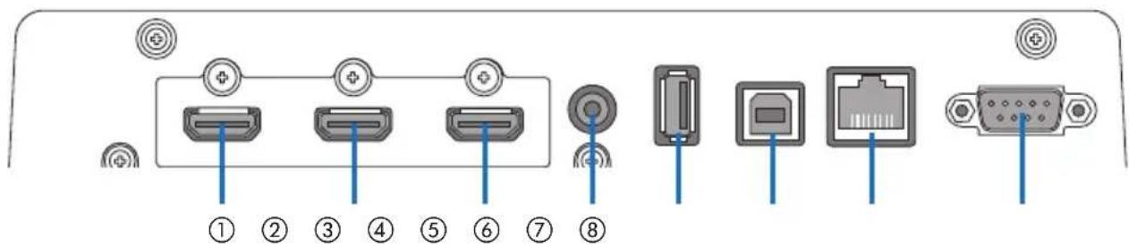
① HDMI1 input terminal
Connect this to the HDMI output terminal of a computer or image device.
② HDMI2 input terminal
Connect this to the HDMI output terminal of a computer or image device.
③ HDMI3/MHL input terminal
Connect this to the HDMI output terminal of a computer or image device. Or connect a device that supports the MHL standard.
④ MIC input terminal
Connect a microphone.
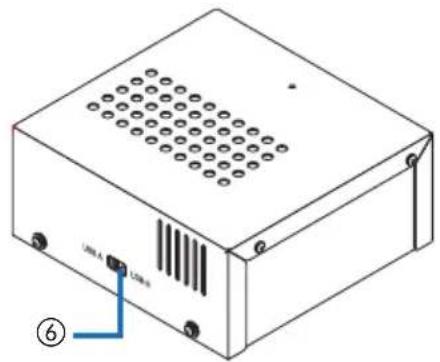
⑤ USB-A port
(This can be used when the receiver box is connected.)
Connect a USB memory device here when using mainly the projector's VIEWER function.
⑥ USB-B port
(This can be used when the receiver box is connected.)
Connect this to the computer's USB-A port when using mainly the projector's Interactive White Board Kit or USB Display function.
⑦ LAN port
(This cannot be used when the receiver box is connected.)
Connect this to the computer's LAN port. Use this to control the projector or display from the computer.
⑧ SERVICE terminal
This terminal is for service purpose only. (Not available for users)
NOTE
- On the interface selector, the USB-A and USB-B ports cannot be used simultaneously. Selection either the USB-A or USB-B port can be performed by the selector switch on the receiver box (see ⑥ on the following page).
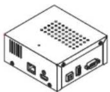
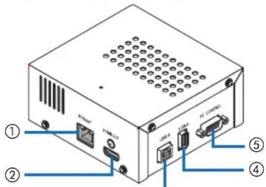
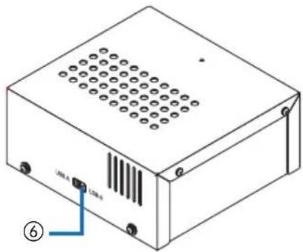
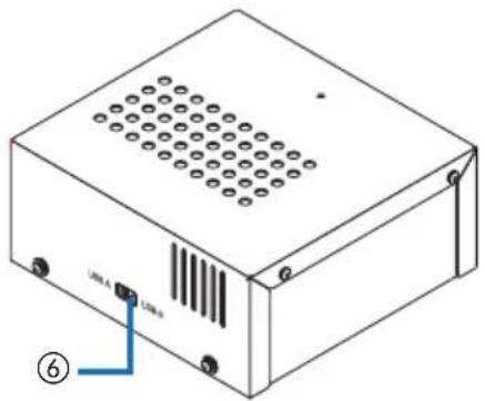
2-2. Receiver box (included with the NP01SW2)
[Left side] [Right side]
③
natural_image
Technical line drawing of a rectangular electronic device with ventilation slots and labeled ports (no text or symbols beyond labels)① HDBaseT port (input)
Connect this to the interface selector's HD-BaseT port (output) by a commercially available LAN cable.
② HDMI output terminal
Connect this to the HDMI input terminal on the projector or display by the included HDMI cable.
③ USB-B port
Connect this to the projector's USB-A port by a commercially available USB cable primary for utilizing the projector's VIEWER function.
④ USB-A port
Connect this to the projector's USB-B port by a commercially available USB cable primary for utilizing the projector's Interactive White Board Kit or USB Display function.
⑤ PC CONTROL terminal
Connect this to the projector's PC CONTROL terminal or the display's RS-232C terminal by the included RS-232C cable.
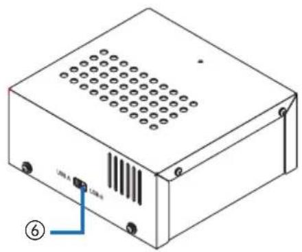
⑥ USB-A/USB-B selector switch
Use this to select either the USB-A or USB-B port on the receiver box. Only one port (USB-A or USB-B) is available on the receiver box.
Make sure to perform switching operation when this product is in powered OFF state. Use a long stick for switching from/to USB-A/USB-B.
| Selector switch (6) Interface selector Receiver box | ||
| USB-A | USB-A: Inactive USB-A: Active | |
| USB-B: Active USB-B: Inactive | ||
| USB-B | USB-A: Active USB-A: Inactive | |
| USB-B: Inactive USB-B: Active | ||
3. Mounting the interface selector on a wall
Mount the mount unit to 2 places on the main unit's rear surface and on the wall where the main unit is to be fixed. Also, use the mount unit to mount the AC adapter onto the wall.
[About the screws]
- Use the 5 screws included with the interface selector (M3). With the NP01SW2, 1 more screw (M3) is included for use with the receiver box.
- In addition to the above screws, prepare 8 pcs of commercially available ∅4 screws to mount the interface selector onto the wall.
NOTE
- Prepare ∅4 screws that have enough durability to support the 1.4kg (3.1bls) interface selector.
- Use a magnetized screwdriver with a thin neck for installing the interface selector on the wall.
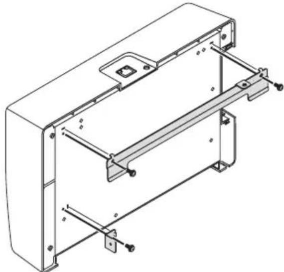
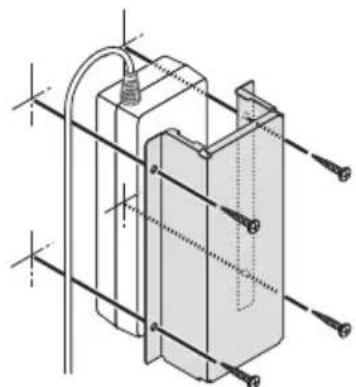
3-1. Mounting the interface selector on a wall
(1) Fasten the main unit mount units (large and small) to the main unit's rear surface.
Fasten using 3 of the included screws (M3).
natural_image
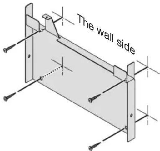
Technical line drawing of a mechanical housing or enclosure with mounting brackets and structural supports (no text or symbols)(2) Fasten the wall mount unit to the wall on which the interface selector is to be fixed.
Fasten by 4 pcs of commercially available ∅4 screws.
ENG-13
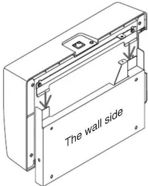
(3) Mount the interface selector onto the wall mount unit.
Slide the interface selector downward to catch it on the wall mount unit's hooks.
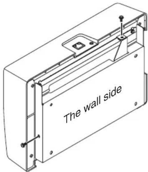
(4) Fasten the top and right sides of interface connector by the included screws.
Use 2 pcs of the included screws (M3).
3-2. Mounting the AC adapter on a wall
(1) Mount the AC adapter onto the mount unit and fasten it on the wall by 4 commercially available screws ( 4 ).
natural_image
Technical line drawing of a mechanical component with mounting holes and internal structure (no text or symbols)4. Mounting the Receiver Box on the Ceiling Mount Unit or on a Wall (for the NP01SW2)
For connecting the receiver box to the projector, fix the receiver box on the projector's ceiling mount unit. In case the ceiling mount unit is not used or you want to connect the receiver box to a display, fix it on a wall near the device. Prepare 1 pc of commercially available ∅4 screw for fixing the receiver box on a wall.
NOTE
- Prepare commercially available ∅4 screws that have enough durability to support the 0.5kg (1.1lbs) receiver box.
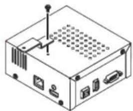
4-1. Fixing the mount unit on the receiver box
(1) Fix the mount unit on the receiver box by the included screw (M3).
natural_image
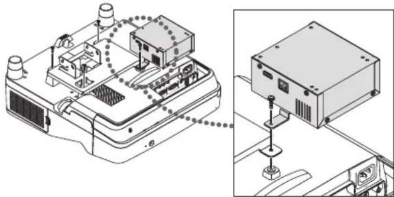
Isometric line drawing of a computer internal unit with ports and connectors (no text or symbols)4-2. In case to fix the receiver box on the ceiling mount unit
(1) When mounting the ceiling mount unit to the projector, fasten both the ceiling mount unit and the receiver box together by one screw.
Fastening examples
natural_image
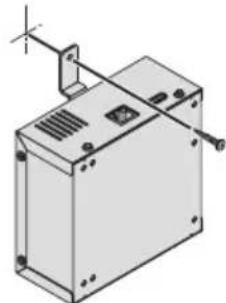
Technical line drawing of an electronic device with internal components and a close-up view of its mounting base (no text or symbols)4-3. In case to fasten the receiver box on a wall
(1) To fasten the receiver box on a wall, use 1 commercially available ∅4 screw.
natural_image
Isometric line drawing of a mechanical enclosure or housing with mounting brackets and a vertical support (no text or symbols)5. Device Connection Examples
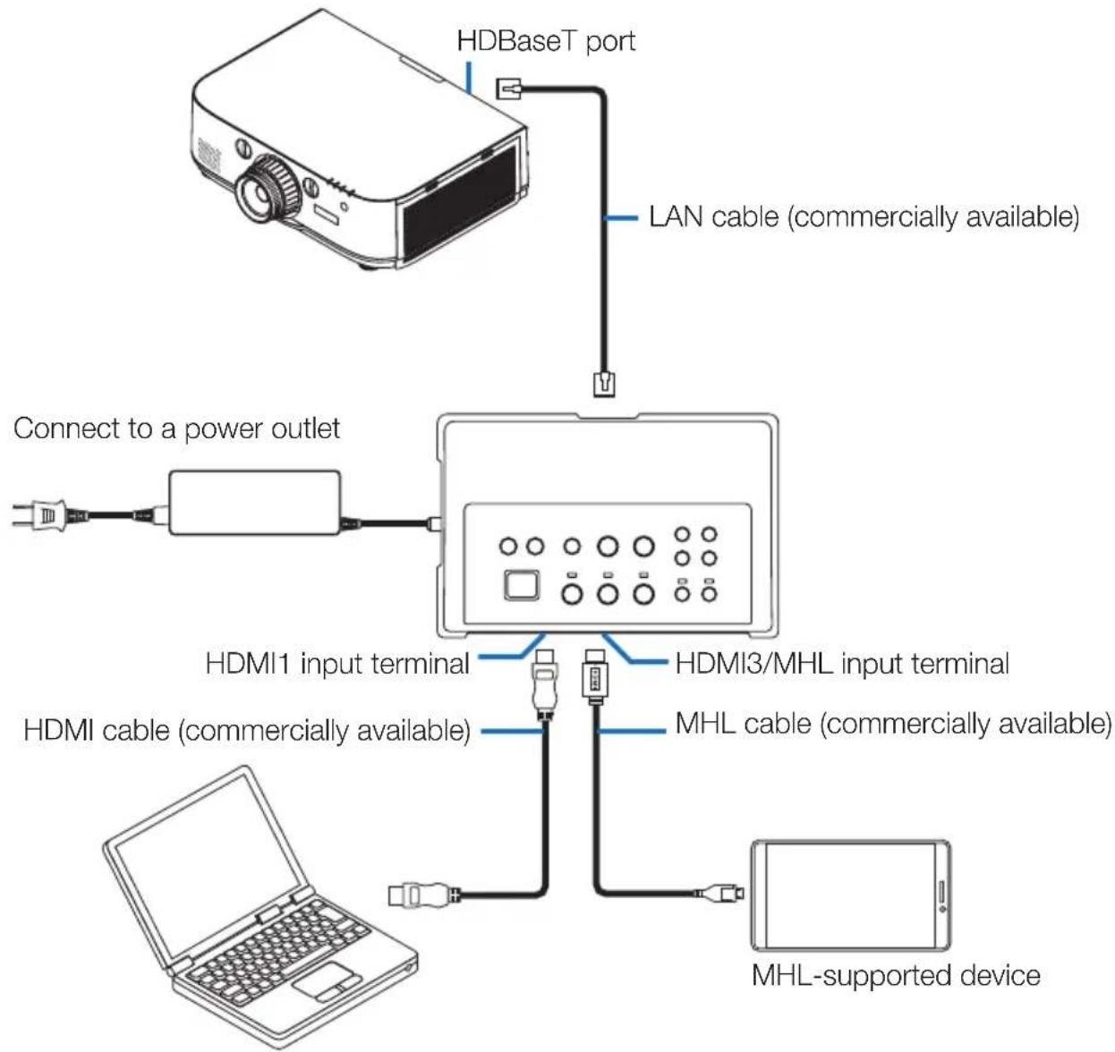
5-1. Projecting the image of a computer, etc.
Connecting to a projector or display equipped the HDBaseT port
flowchart
graph TD
    A["HDBaseT port"] --> B["LAN cable (commercially available)"]
    B --> C["Connect to a power outlet"]
    C --> D["HDMI1 input terminal"]
    C --> E["HDMI3/MHL input terminal"]
    C --> F["HDMI cable (commercially available)"]
    F --> G["MHL cable (commercially available)"]
    G --> H["MHL-supported device"]
NOTE
- Use an MHL cable (commercially available) conforming to standards.
Using a cable not conforming to standards could lead to fire, injury or damage to the surroundings when charging the MHL-compatible device. - If a (commercially available) MHL-HDMI converter/adapter is used for connection, battery charge feature and the remote control functions may not work.
- If the picture is not properly displayed, disconnect then reconnect the MHL cable.
- The picture may not be displayed properly depending on the type of smartphone or tablet, its settings, etc.
- When the receiver box is not connected, the interface selector's USB-A and USB-B ports cannot be used.
For your reference
- The MHL-compatible device cannot be charged in the cases below.
- When the MHL supported device has no battery power
- When the power consumption is greater than the amount of power supplied
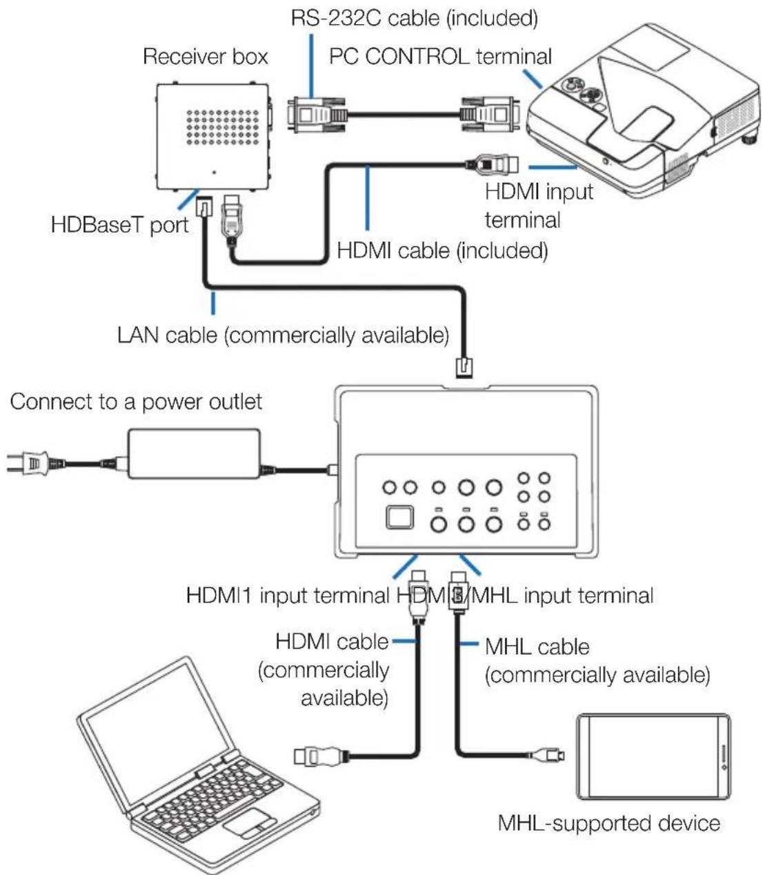
Connecting to a projector or display not equipped the HDBaseT port
Connect the receiver box included with the NP01SW2.
flowchart
graph TD
    A["HDBaseT port"] -->|LAN cable (commercially available)| B["Connect to a power outlet"]
    B --> C["HDMI1 input terminal"]
    C --> D["MHL cable (commercially available)"]
    D --> E["MHL-supported device"]
    F["Receiver box"] --> G["RS-232C cable (included)"]
    G --> H["PC CONTROL terminal"]
    I["HDMI cable (included)"] --> J["HDMI input terminal"]
    K["PCI"] --> L["PCI"]
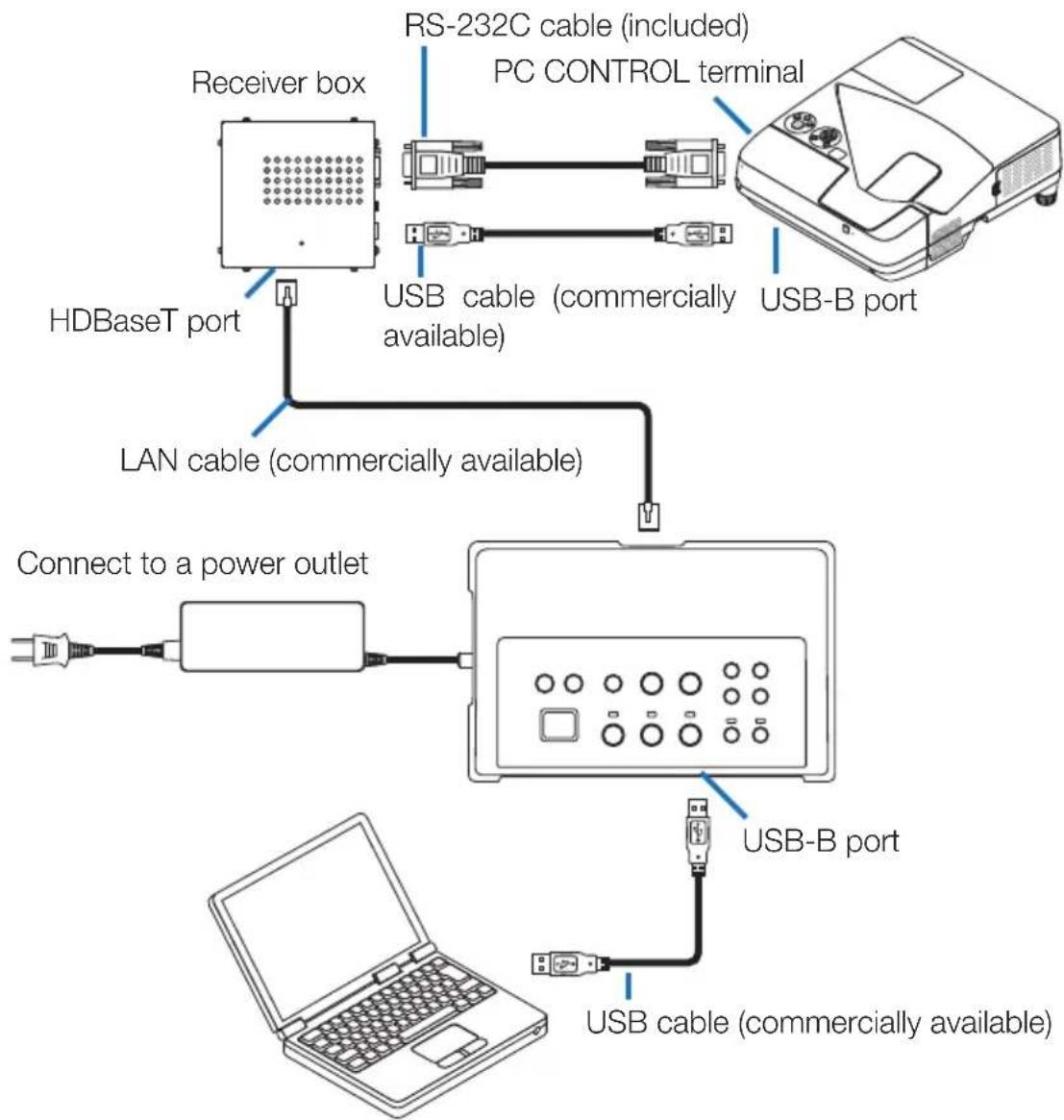
Connecting to a computer not equipped the HDMI output terminal
- Use the projector's USB Display function. Not support connection with displays. Some models are not equipped with the USB Display function. Check your projector's user's manual or the NEC website to see if your projector is equipped with the USB Display function.
- Connect the receiver box included with the NP01SW2.
IMPORTANT
- For utilizing the USB Display function, switch the receiver box's USB-A/USB-B selector switch to "USB-A" before connecting the cable.
flowchart
graph TD
    A["Receiver box"] -->|RS-232C cable (included) PC CONTROL terminal| B["PC monitor"]
    A -->|USB cable (commercially available)| C["USB-B port"]
    D["HDBaseT port"] -->|LAN cable (commercially available)| C
    E["Connect to a power outlet"] --> F["PC monitor"]
    G["Laptop"] --> H["USB port"]
    I["USB cable (commercially available)"] --> H
    style A fill:#f9f,stroke:#333
    style B fill:#ccf,stroke:#333
    style C fill:#cfc,stroke:#333
    style D fill:#fcc,stroke:#333
    style E fill:#cff,stroke:#333
    style F fill:#ffc,stroke:#333
    style G fill:#fcc,stroke:#333
    style H fill:#ffc,stroke:#333
NOTE
- Switching to the USB Display function can be performed by the Image Express Utility Lite booted on a computer.
Switching to the USB Display function using the projector's remote control, operate the remote control pointing it towards the remote sensor on the projector. When a receiver box is connected, the interface selector's remote sensor is not available.
- When computers are connected to both the interface selector's HDMI input terminal and USB-B port, the screen of the computer connected to the USB-B port is displayed directly after the interface selector's power is turned on.
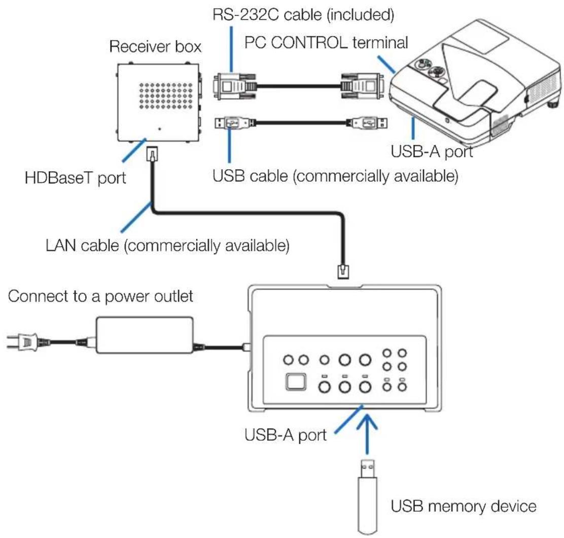
Utilizing the VIEWER function on the projector by this product with the USB memory
- Not support connection with displays.
Some models are not equipped with the VIEWER function. Check your projector's user's manual or the NEC web site to see if your projector is equipped with the VIEWER function.
- Connect the receiver box included with the NP01SW2.
IMPORTANT
- For utilizing the VIEWER function, switch the receiver box's USB-A/USB-B selector switch to "USB-B" before connecting the cable.
flowchart
graph TD
    A["Receiver box"] --> B["HDBaseT port"]
    B --> C["LAN cable (commercially available)"]
    C --> D["Connect to a power outlet"]
    D --> E["USB-A port"]
    E --> F["USB memory device"]
    G["RS-232C cable (included)"] --> H["PC CONTROL terminal"]
    I["USB cable (commercially available)"] --> J["USB-A port"]
NOTE
- Use the projector's remote control to switch to the VIEWER function. The interface selector's remote sensor is not available when a receiver box is connected, so operate the remote control pointing it towards the remote sensor on the projector.
Connecting to a projector or display with the SB-07BC option board inserted in its slot
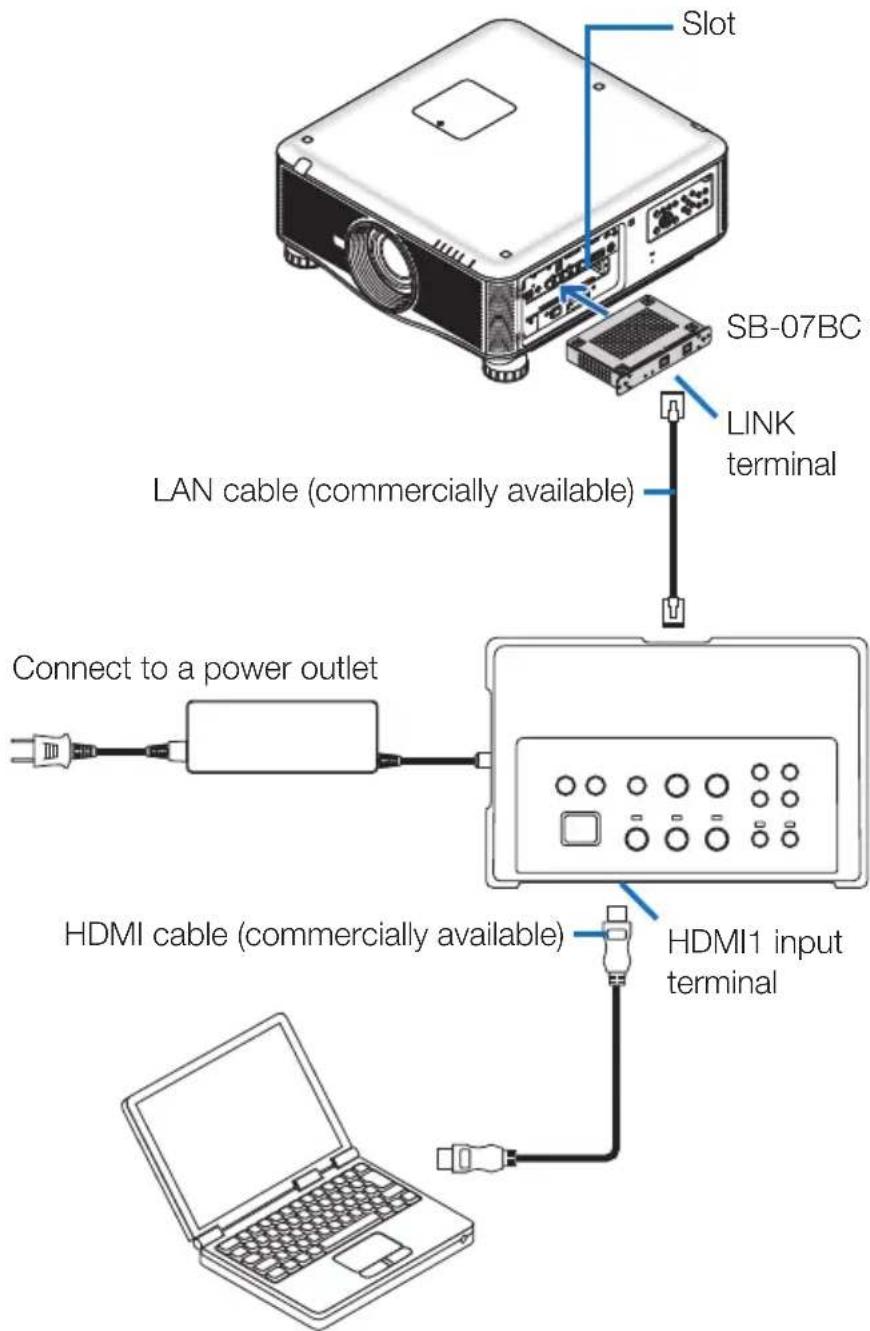
NOTE
- When the receiver box is not connected, the interface selector's USB-A and USB-B ports are not available.
- The below mentioned buttons on this product are not available when the SB-07BC loaded projector is connected with this product.
POWER ON/OFF, SETUP, AUDIO MUTE, AV MUTE, VOLUME +/-
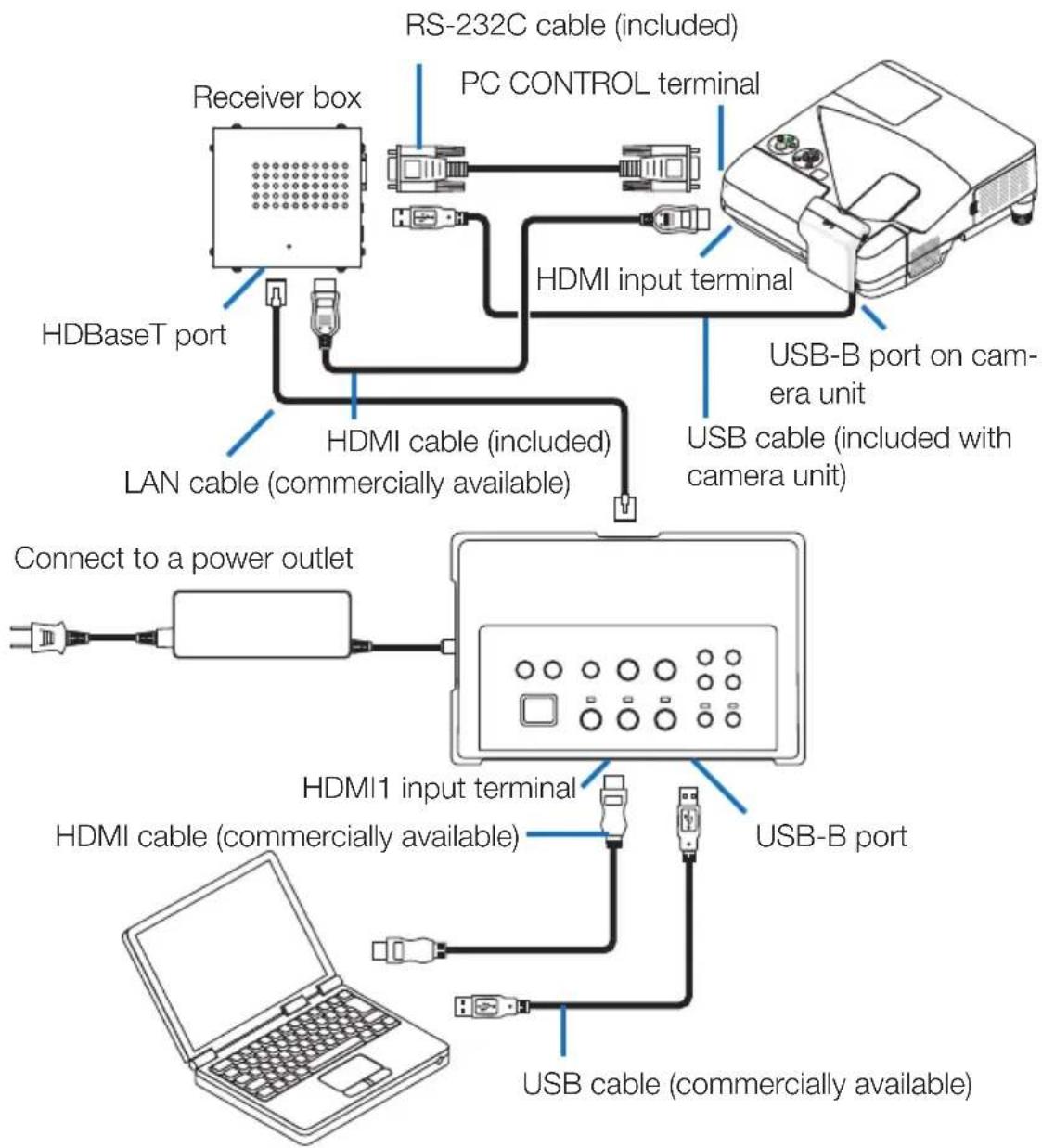
5-2. Using separately sold Interactive White Board Kit for the projector
Connect the receiver box included with the NP01SW2.
IMPORTANT
- For utilizing the Interactive White Board Kit function, switch the receiver box's USB-A/USB-B selector switch to "USB-A" before connecting the cable.
flowchart
graph TD
    A["Receiver box"] --> B["HDBaseT port"]
    B --> C["HDMI cable (included)"]
    C --> D["LAN cable (commercially available)"]
    D --> E["Connect to a power outlet"]
    E --> F["HDMI1 input terminal"]
    F --> G["USB-B port"]
    F --> H["USB cable (commercially available)"]
    H --> I["PC CONTROL terminal"]
    I --> J["RS-232C cable (included)"]
    J --> K["HDMI input terminal"]
    K --> L["USB-B port on camera unit"]
    K --> M["USB cable (included with camera unit)"]
NOTE
- The USB Display function is unavailable when the Interactive White Board Kit (sold separately) is connected.
- Please connect the USB cable to the USB-B port on the projector for using the stylus pen which controlled by the IWB software installed computer connecting with the projector that has the built-in interactive white board function as NP-UM352W. In this case, add check mark to REMOTE PEN for the PEN SETTINGS on the projector's APPS menu.
5-3. Using built-in Touch Panel display
Connect the receiver box included with NP01SW2 same as 5-2 Using separately sold Interactive White Board Kit for the projector described on the previous page.
IMPORTANT
- For utilizing the built-in Touch Panel display, switch the receiver box's USB-A/USB-B selector switch to "USB-A" before connecting the cable.
For connection between the built-in Touch Panel display and the receiver box, make sure to use the cables listed below same as 5-2 Using separately sold Interactive White Board Kit for the projector described on the previous page.
• HDMI cable (Included)
• RS-232C cable (Included)
- USB cable (Included with the built-in Touch panel display)
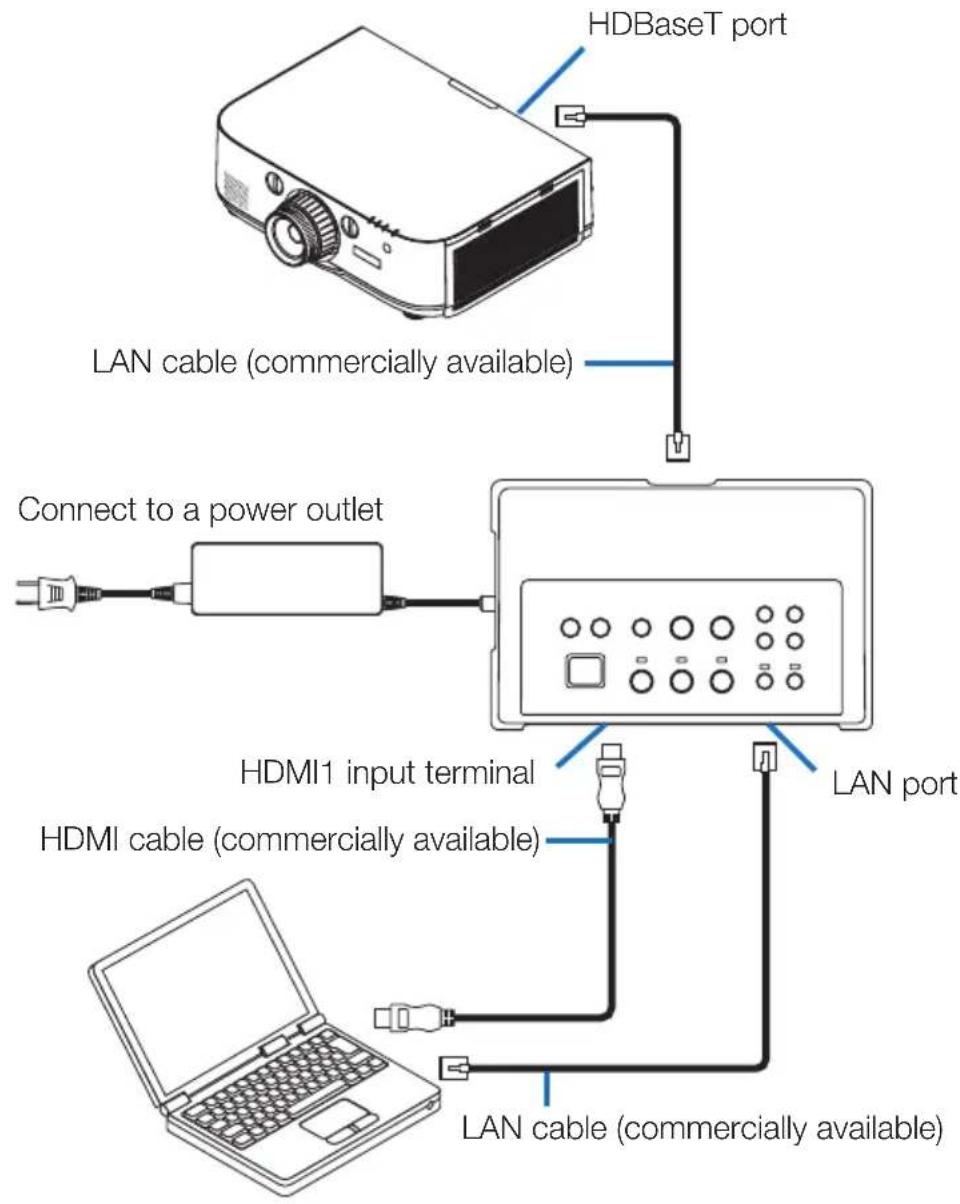
5-4. Controlling the projector or display via LAN
flowchart
graph TD
    A[" projector"] -->|HDBaseT port| B["LAN cable (commercially available)"]
    B --> C["Connect to a power outlet"]
    C --> D["Digital display"]
    D -->|LAN port| E["LAN cable (commercially available)"]
    E --> F["HI/MI cable (commercially available)"]
    F --> G["HI/MI1 input terminal"]
    G --> H["Laptop"]
NOTE
- When a receiver box is connected, the projector or display cannot be controlled via LAN.
6-1. Interface selector (common for both the NP01SW1 and NP01SW2)
| Input terminals | HDMI | HDMI connector type A × 3[Video Inputs]Deep Color: 8/10/12-bits supportedColorimetry: RGB, YCbCr444 and YCbCr422 supportedLipSync, HDCP*1, 4K and 3D supported[Audio Input]LPCM sampling frequency: 32/44.1/48 kHz |
| USB-A USB type A | × 1 | |
| USB-B USB type B | × 1 | |
| LAN*2 | RJ-45 × 1, BASE-TX supported | |
| Microphone Monaural mini-jack × 1 | ||
| Service D-Sub 9-pin | × 1 | |
| Output terminals | HDBaseT*3 | RJ-45 × 1 |
| Power supply voltage | 19.5 V | |
| Power consumption | 21 W (100-240 V AC)(0.1 W in the state the main power switch is off)* Including power consumption of the AC adapter. | |
| 19.5 W (DC) | ||
| External dimensions | 285 (W) × 64 (H) × 187 (D) mm/11.2 (W) × 2.5 (H) × 7.4 (D) inches | |
| Weight 1.4Kg (3.1lbs) | ||
| Usage environment | Operating temperature 5 - | 40°C |
| Operating humidity 20 - 80 | % (no condensation) | |
| Storage temperature -10 - | 50°C | |
| Storage humidity 20 - 80% | (no condensation) | |
6-2. AC adapter(common for both the NP01SW1 and NP01SW2)
| Model Number | AD1930 |
| Input 100-240 V AC | ± 10% 50/60Hz, 1.4A |
| Output 19.5 V DC, 3.05A | |
6-3. Receiver box (included with the NP01SW2)
| Model Number N | P01R | |
| Input terminal HD | BaseT^*3 | RJ-45 × 1 |
| Output terminals | HDMI | HDMI connector type A ×1[Video Outputs]Deep Color: 8/10/12-bits supported*4Colorimetry: RGB, YCbCr444 and YCbCr422 supportedLipSync, HDCP*, Not supported 4K, Supported 3D*5[Audio Output]LPCM sampling frequency: 32/44.1/48 kHz |
| USB-A USB type A ×1 | ||
| USB-B USB type B ×1 | ||
| PC control D-Sub 9-pin ×1 | ||
| External dimen-sions | 126 (W) × 52 (H) × 119(D) mm/4.9 (W) × 2.1 (H) × 4.7 (D) inches120 (W) × 52 (H) × 113 (D) mm/4.7 (W) × 2.1 (H) × 4.5 (D) inches (not including pro-truded parts) | |
| Weight 0.5kg/1.1 | Ibs | |
| Usage environ-ment | Operating temperature 5 - | 40°C |
| Operating humidity 20 - 80 | % (no condensation) | |
| Storage temperature -10 - | 50°C | |
| Storage humidity 20 - 80% | (no condensation) | |
*1 Definition of HDCP and HDCP technology
HDCP is the abbreviation of "High-bandwidth Digital Content Protection", a system protecting copyrights whose purpose is to prevent illicit copying of digital contents sent via DisplayPort or HDMI interface. HDCP standards are established and managed by a group called Digital Content Protection, LLC.
On this product, HDCP technology is used for the HDMI input terminal and HDBaseT port. Digital contents that are copyright-protected using HDCP technology can be projected using this product's HDMI input terminal and HDBaseT port.
However, images from the HDMI input port or HDBaseT port may not display due to changes to HDCP standards or for other reasons, even if this product is functioning properly.
*2 T his product's LAN port does not support PoE. Connecting this product's LAN port to a network supplying electric power could result in combustion or damage.
*3 U se a commercially available LAN cable of the type described below for connection to the HDBaseT port.
| Condition | Cable length | Cable specification |
| Not connected to receiver box | Max. 100 m (for 4K signals, maximum 70 m) | CAT5e or greater STP cableRecommended thickness AWG23 |
| Connected to receiver box | Max. 30 m | CAT6A or greater STP cableRecommended thickness AWG23 |
NOTE: Performance may not be satisfactory with some cables.
*4 1 080p signal supports up to 8 bit signal.
On the other hand, signal as 1080i, 720p, 480p, and 480i, etc. support up to 12 bit signal.
*5 D oes not support signal exceeds 1080p 30Hz and 1080i 60Hz, etc.
Serie NP01SW (NP01SW1/NP01SW2)
Aufbauanleitung
Inhalt
Einführung......GER-2
natural_image
Line drawing of a rectangular electronic device with ports and buttons (no text or symbols)natural_image
Simple line drawing of a mechanical component with flanges and end caps (no text or symbols)natural_image
Isometric line drawing of a rectangular metal frame with mounting holes (no text or symbols)□ Montageschrauben (M3) 5

natural_image
Illustration of a rectangular device connected to a coiled cable with connectors (no text or symbols)natural_image
Two identical wire-wrapped electrical connectors with metal contacts and connectors (no text or symbols)natural_image
Simple geometric shape: a tilted square with no text or symbols
natural_image
Isometric line drawing of a computer or hardware unit with ports and ventilation slots (no text or symbols)③
natural_image
Technical line drawing of a rectangular electronic device with ventilation slots and labeled ports (no text or symbols beyond labels)natural_image
Technical line drawing of a mechanical housing or enclosure with mounting brackets and mounting holes (no text or symbols)natural_image
Technical line drawing of a mechanical component with mounting holes and internal structure (no text or symbols)natural_image
Isometric line drawing of a computer chassis with ventilation slots and ports (no text or symbols)natural_image
Technical diagram of an electronic device with connected components and a close-up view showing internal wiring (no text or symbols)natural_image
Isometric line drawing of a rectangular electronic device with mounting holes and a vertical axis indicator (no text or symbols)Série NP01SW (NP01SW1/NP01SW2)
Introduction....FRE-2
natural_image
Line drawing of a rectangular electronic device with ports and buttons (no text or symbols)natural_image
Pure technical line drawing of a mechanical component (no text or symbols)natural_image
Isometric line drawing of a rectangular metal frame with mounting holes (no text or symbols)□ Vis de montage (M3) 5
natural_image
Line drawing of a rectangular electronic device with a coiled cable and connector (no text or symbols)□ Manuel d'installation (7N8N673□) (ce manuel)

natural_image
Two identical wireCoiled cable components with connectors, shown from different angles (no text or symbols)natural_image
Simple geometric shape: a tilted square with no text or symbols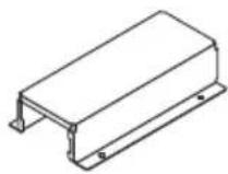
natural_image
Isometric line drawing of a computer or hardware unit with ports and ventilation slots (no text or symbols)③

natural_image
Technical line drawing of a rectangular electronic device with ventilation slots and labeled ports (no text or symbols beyond labels)natural_image
Technical line drawing of a mechanical housing or enclosure with mounting brackets and structural supports (no text or symbols)natural_image
Technical line drawing of a mechanical component with mounting holes and internal structure (no text or symbols)natural_image
Isometric line drawing of a computer chassis with ventilation slots and ports (no text or symbols)natural_image
Technical line drawing of an electronic device with a close-up view showing internal components and wiring (no text or symbols)natural_image
Isometric line drawing of a mechanical enclosure or housing with mounting holes and a vertical support (no text or symbols)POWER ON/OFF, SETUP, AUDIO MUTE, AV MUTE, VOLUME +/-
Serie NP01SW (NP01SW1/NP01SW2)
Comuni per NP01SW1 e NP01SW2
natural_image
Line drawing of a rectangular electronic device with ports and buttons (no text or symbols)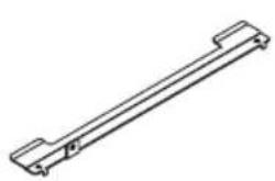
natural_image
Simple line drawing of a mechanical component with two flanged ends (no text or symbols)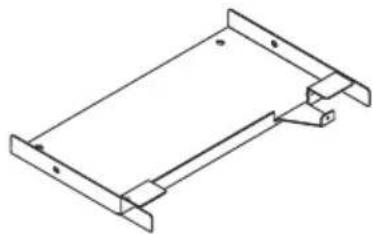
natural_image
Isometric line drawing of a rectangular metal frame with mounting holes (no text or symbols)natural_image
Illustration of a rectangular device with a coiled cable and connector (no text or symbols)
natural_image
Two identical wire-wrapped electrical connectors with metal contacts and connectors (no text or symbols)natural_image
Simple geometric shape: a tilted square with no text or symbols
natural_image
Isometric line drawing of a computer or hardware unit with ports and ventilation grille (no text or symbols)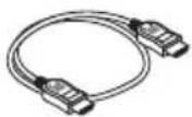
③

natural_image
Technical line drawing of a rectangular electronic device with ventilation slots and labeled ports (no text or symbols beyond labels)①Porta HDBaseT (ingresso)
natural_image
Technical line drawing of a mechanical housing or enclosure with mounting brackets and structural supports (no text or symbols)natural_image
Technical line drawing of a mechanical component with mounting holes and internal structure (no text or symbols)natural_image
Isometric line drawing of a device chassis with ports and connectors (no text or symbols)natural_image
Technical line drawing of an electronic device with internal components and a close-up view of its mounting bracket (no text or symbols)natural_image
Isometric technical drawing of a mechanical enclosure or housing with mounting brackets and a vertical support (no text or symbols)POWER ON/OFF, SETUP, AUDIO MUTE, AV MUTE, VOLUME +/-
Serie NP01SW (NP01SW1/NP01SW2)
natural_image
Line drawing of a rectangular electronic device with ports and buttons (no text or symbols)□ Adaptador de CA (3N10206□) 1
natural_image
Isometric line drawing of a rectangular metal frame with mounting holes (no text or symbols)natural_image
Line drawing of a rectangular electronic device with a coiled cable and connector (no text or symbols)□ Manual de instalación (7N8N673□) (este manual)
natural_image
Two identical wire-wrapped electrical connectors with metal contacts (no text or symbols)natural_image
Simple geometric shape: a tilted square with no text or symbols
natural_image
Isometric line drawing of a computer or hardware unit with ports and ventilation grille (no text or symbols)① Terminal de entrada HDMI1
natural_image
Technical line drawing of a rectangular electronic device with ventilation slots and labeled ports (no text or symbols beyond labels)natural_image
Technical line drawing of a mechanical housing or enclosure with mounting brackets and structural supports (no text or symbols)natural_image
Technical line drawing of a mechanical component with mounting holes and internal structure (no text or symbols)natural_image
Isometric line drawing of a computer chassis with ventilation slots and ports (no text or symbols)natural_image
Technical line drawing of an electronic device with internal components and a close-up view of its mounting base (no text or symbols)natural_image
Isometric line drawing of a mechanical or electronic device with mounting bracket and control panel (no text or symbols)POWER ON/OFF, SETUP, AUDIO MUTE, AV MUTE, VOLUME +/-
Série NP01SW (NP01SW1/NP01SW2)
natural_image
Line drawing of a rectangular electronic device with ports and buttons (no text or symbols)□ Adaptador AC (3N10206□) 1
natural_image
Isometric line drawing of a rectangular metal frame with mounting holes (no text or symbols)natural_image
Simple line drawing of a rectangular device with a coiled cable and connector (no text or symbols)natural_image
Two identical wireCoiled cable connectors with metal clamps (no text or symbols)natural_image
Simple geometric shape: a tilted square with no text or symbols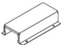
natural_image
Isometric line drawing of a computer internal unit (no text or symbols)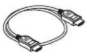
① terminal de entrada HDMI1
Conecte este ao terminal de saída HDMI de um computador ou dispositivo de imagem.
③

natural_image
Technical line drawing of a rectangular electronic device with ventilation slots and labeled ports (no text or symbols beyond labels)① porta HDBaseT (entrada)
natural_image
Technical line drawing of a mechanical housing or enclosure with mounting brackets and structural supports (no text or symbols)(2) Prenda a unidade de montagem de parede à parede na qual o seletor de interface será fixado.
natural_image
Technical line drawing of a mechanical component with mounting holes and internal structure (no text or symbols)natural_image
Isometric line drawing of a computer chassis with ventilation slots and ports (no text or symbols)natural_image
Technical line drawing of an electronic device with connected components and a close-up view of its internal structure (no text or symbols)natural_image
Isometric line drawing of a rectangular electronic device with mounting holes and a vertical support (no text or symbols)5. Exemplos de conexão de dispositivos
POWER ON/OFF, SETUP, AUDIO MUTE, AV MUTE, VOLUME +/-
natural_image
Line drawing of a rectangular electronic device with ports and buttons (no text or symbols)natural_image
Pure technical line drawing of a mechanical component (no text or symbols)natural_image
Isometric line drawing of a rectangular metal frame with mounting holes (no text or symbols)natural_image
Line drawing of a rectangular electronic device with a coiled cable and connector (no text or symbols)natural_image
Simple geometric shape: a tilted parallelogram with no text or symbolsnatural_image
Two identical wire-wrapped electrical connectors with metal contacts and connectors (no text or symbols)natural_image
Isometric line drawing of a computer internal unit (no text or symbols)③

natural_image
Technical line drawing of a rectangular electronic device with ventilation slots and labeled ports (no text or symbols beyond labels)natural_image
Technical line drawing of a mechanical housing or enclosure with mounting brackets and internal components (no text or symbols)natural_image
Technical line drawing of a mechanical component with mounting holes and internal structure (no text or symbols)natural_image
Isometric line drawing of a computer internal unit with ports and ventilation slots (no text or symbols)natural_image
Technical line drawing of an electronic device with internal components and a close-up view of its mounting base (no text or symbols)natural_image
Isometric line drawing of a rectangular electronic device with mounting holes and a vertical support (no text or symbols)NP01SW 시리즈 (NP01SW1/NP01SW2)
설치 설명서
목차
개요......KOR-2
natural_image
Line drawing of a rectangular electronic device with ports and buttons (no text or symbols)natural_image
Illustration of a rectangular electronic device connected to a coiled cable (no text or symbols visible)natural_image
Simple geometric shape: a tilted square with no text or symbolsnatural_image
Simple line drawing of a mechanical component with two flanged ends (no text or symbols)natural_image
Isometric line drawing of a rectangular metal frame with mounting holes (no text or symbols)natural_image
Two identical wire-wrapped electrical connectors with metal contacts and connectors (no text or symbols)natural_image
Isometric line drawing of a computer or hardware unit with ports and ventilation grille (no text or symbols)□장착 장치 (24H8243□) 1

□ HDMI 케이블 (7N960240) 1
□ RS-232C 케이블 (7N960241) 1

□장착 나사 (M3) 1

참고 사항
① HDMI1 입력 단자
③
natural_image
Technical line drawing of a rectangular electronic device with ventilation slots and labeled ports (no text or symbols beyond labels)① HDBaseT 포트 (입력)
natural_image
Technical line drawing of a mechanical enclosure or housing frame with mounting brackets and mounting holes (no text or symbols)natural_image
Technical diagram of a structural frame with mounting brackets and support columns (no text or symbols)natural_image
Technical line drawing of a mechanical component with mounting holes and internal structure (no text or symbols)natural_image
Isometric line drawing of a device chassis with ports and connectors (no text or symbols)natural_image
Technical line drawing of an electronic device with a close-up view showing internal components and wiring (no text or symbols)natural_image
Isometric technical drawing of a mechanical device with mounting bracket and wiring (no text or symbols)5-1. 컴퓨터 등의 영상 투사하기
POWER ON/OFF, SETUP, AUDIO MUTE, AV MUTE, VOLUME +/-
natural_image
Line drawing of a rectangular electronic device with ports and buttons (no text or symbols)□ AC 適配器 (3N10206□) 1
natural_image
Simple line drawing of a mechanical component with two flanged ends (no text or symbols)natural_image
Isometric line drawing of a rectangular metal frame with mounting holes (no text or symbols)□ 安装螺絲 (M3) 5

natural_image
Illustration of a rectangular electronic device connected to a coiled cable with connectors (no text or symbols)natural_image
Line drawing of a coiled electrical plug with connectors (no text or symbols)natural_image
Simple geometric shape: a tilted square with no text or symbols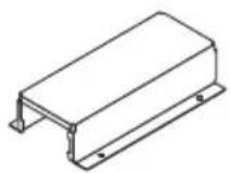
NP01SW2 另外附随了下列物件:
natural_image
Isometric line drawing of a computer or hardware unit with ports and ventilation slots (no text or symbols)□ 安装配件 (24H8243□) 1
□ 安装螺絲 (M3) 1

参考
① HDMI1 輸入端子
natural_image
Technical line drawing of a rectangular electronic device with ventilation slots and labeled ports (no text or symbols beyond labels)① HDBaseT 埠 (輸入)
natural_image
Technical line drawing of a mechanical housing or enclosure with mounting brackets and structural supports (no text or symbols)natural_image
Technical line drawing of a mechanical component with no visible text or symbolsnatural_image
Isometric line drawing of a computer chassis with ports and connectors (no text or symbols)natural_image
Technical line drawing of an electronic device with internal components and a close-up view of its mounting base (no text or symbols)4-3. 在牆壁上固定接收盒的情況下
natural_image
Isometric line drawing of a rectangular electronic device with mounting holes and a vertical rod (no text or symbols)5. 設備連接示例
5-1. 投射電腦等的影像
natural_image
Line drawing of a rectangular electronic device with ports and buttons (no text or symbols)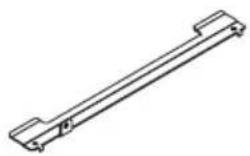
natural_image
Pure technical line drawing of a mechanical component (no text or symbols)□取り付け金具(本体用:小)
(24H8242□) 1 個
natural_image
Isometric line drawing of a rectangular metal frame with flanged edges and mounting holes (no text or symbols)□取り付け用ネジ(M3)
5本

natural_image
Illustration of a rectangular electronic device with a coiled cable and connector (no text or symbols)
natural_image
Line drawing of a coiled electrical plug with connectors (no text or symbols)natural_image
Simple geometric shape: a tilted square with no text or symbols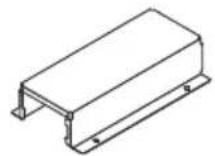
natural_image
Isometric line drawing of a device chassis with ports and ventilation grille (no text or symbols)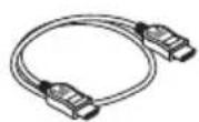
□取り付け金具(24H8243□)
主電源スイッチ
本製品の電源の入り切りを行います。
注意
① HDMI1 入力端子
③
natural_image
Isometric line drawing of a rectangular electronic device with ventilation slots and labeled ports (no text or symbols beyond labels)① HDBaseT ポート(入力)
natural_image
Technical line drawing of a mechanical enclosure or enclosure frame with mounting brackets and structural supports (no text or symbols)natural_image
Technical line drawing of a mechanical component with mounting holes and internal structure (no text or symbols)natural_image
Isometric line drawing of a computer internal unit with ports and connectors (no text or symbols)natural_image
Technical line drawing of an electronic device with internal components and a close-up view of its mounting base (no text or symbols)4-3. 壁に固定する場合
natural_image
Isometric technical drawing of a mechanical enclosure or housing with mounting holes and a vertical support (no text or symbols)5-1. コンピュータなどの画面を映す
This warranty is valid only in Japan.
| 年 月 日 | サービス内容 担当者 | |||
• Turkish RoHS information relevant for Turkish market
- Ukrainian RoHS Information relevant for Ukrainian market
D-80637 Munchen, Germany
Telephone: +49 89 99699 0
Email: Infomail@nec-display.com
In North and South America
NEC Display Solutions of America, Inc.
Address:
500 Park Boulevard, Suite 1100,
Itasca, Illinois 60143 U.S.A.
Telephone: +1 800 836 0655
Email: pjtechsupport@necdisplay.com
In Oceania
Australia, DrGroup Global
Address:
Unit 3, 277-281 Sir Donald Bradman Drive,
DOWANDILLA SPA 5033
CUSTOMER CALL CENTRE:
Telephone: 1300 632 435
Email: necsupport@thedrgroup.com.au
New Zealand, DrGroup ZN
Address:
28 Walls Road, Penrose,
Auckland, New Zealand
CUSTOMER CALL CENTRE:
Telephone: 0508 855 911
Email: necsupport@thedrgroup.co.nz
In Asia
NEC Display Solutions, Ltd.
Address:
686-1, Nishioi, Oi-Machi,
Ashigarakami-Gun, Kanagawa 258-0117, Japan
Telephone: +81 465 85 2369
NEC (China) Co., Ltd.
Address:
6F, Landmark diplomatic offi ce building D2,
No. 19 East Road, Chaoyang District,
Beijing 100600, R.P.C.
Telephone: 010-59342706
NEC Hong Kong Ltd.
Address:
25/F, The Metropolis Tower, 10 Metropolis
Drive,
Hunghom, Kowloon, Hong Kong
Telephone: +852 2369 0335
NEC Taiwan Ltd.
Address:
7F, No. 167, SEC. 2, Nan King East Road,
Taipei, Taiwan, R.O.C.
Telephone: +886 2 8500 1710
NEC Asia Pacific Pte. Ltd.
Address:
80 Bendemeer Road,
05-01/02 Hyfl ux Innovation Centre,
Singapore 339949
Telephone: +65 6799 6188
NEC Corporation of Malaysia Sdn Bhd
Address:
Suite 20-01, Level 20,
The Gardens North Tower,
Mid Valley City, Lingkaran Syed Putra,
59200 Kuala Lumpur
Telephone: +603-2299 6322
- Safety requirement in Singapore:
- Interface selector
- NP01SW series (NP01SW1/NP01SW2)
- Installation Manual
- Contents
- NOTE
- Disposing of your used product
- IMPORTANT INFORMATION
- SETUP Button on this product
- Cautions
- Read This Before Starting
- About the pictograms
- WARNING
- CAUTION
- Other Cautions
- DOC Compliance Notice (for Canada only)
- RF Interference (for USA only)
- WARNING TO CALIFORNIA RESIDENTS:
- DECLARATION OF CONFORMITY
- Packaged Items
- Common for both the NP01SW1 and NP01SW2
- The NP01SW2 additionally includes the following items:
- For your reference
- Part Names
- 2-1. Interface selector
- DC IN terminal
- Main power switch
- Attention:
- HDBaseT port (output)
- Operation button/indicator section
- Connection terminal section (inputs)
- ① HDMI1 input terminal
- ② HDMI2 input terminal
- ③ HDMI3/MHL input terminal
- ④ MIC input terminal
- ⑤ USB-A port
- ⑥ USB-B port
- ⑦ LAN port
- ⑧ SERVICE terminal
- 2-2. Receiver box (included with the NP01SW2)
- ① HDBaseT port (input)
- ② HDMI output terminal
- ③ USB-B port
- ④ USB-A port
- ⑤ PC CONTROL terminal
- ⑥ USB-A/USB-B selector switch
- Mounting the interface selector on a wall
- [About the screws]
- 3-1. Mounting the interface selector on a wall
- 3-2. Mounting the AC adapter on a wall
- Mounting the Receiver Box on the Ceiling Mount Unit or on a Wall (for the NP01SW2)
- 4-1. Fixing the mount unit on the receiver box
- 4-2. In case to fix the receiver box on the ceiling mount unit
- 4-3. In case to fasten the receiver box on a wall
- Device Connection Examples
- 5-1. Projecting the image of a computer, etc.
- Connecting to a projector or display not equipped the HDBaseT port
- Connecting to a computer not equipped the HDMI output terminal
- IMPORTANT
- Utilizing the VIEWER function on the projector by this product with the USB memory
- Connecting to a projector or display with the SB-07BC option board inserted in its slot
- 5-2. Using separately sold Interactive White Board Kit for the projector
- 5-3. Using built-in Touch Panel display
- 5-4. Controlling the projector or display via LAN
- 6-3. Receiver box (included with the NP01SW2)
- Serie NP01SW (NP01SW1/NP01SW2)
- Aufbauanleitung
- Inhalt
- Série NP01SW (NP01SW1/NP01SW2)
- Comuni per NP01SW1 e NP01SW2
- ①Porta HDBaseT (ingresso)
- ① Terminal de entrada HDMI1
- ① porta HDBaseT (entrada)
- Exemplos de conexão de dispositivos
- NP01SW 시리즈 (NP01SW1/NP01SW2)
- 설치 설명서
- 목차
- 참고 사항
- ① HDMI1 입력 단자
- ① HDBaseT 포트 (입력)
- 5-1. 컴퓨터 등의 영상 투사하기
- NP01SW2 另外附随了下列物件:
- 参考
- ① HDMI1 輸入端子
- ① HDBaseT 埠 (輸入)
- 4-3. 在牆壁上固定接收盒的情況下
- 設備連接示例
- 5-1. 投射電腦等的影像
- 主電源スイッチ
- 注意
- ① HDMI1 入力端子
- ① HDBaseT ポート(入力)
- 4-3. 壁に固定する場合
- 5-1. コンピュータなどの画面を映す
- In North and South America
- In Oceania
- In Asia
- 05-01/02 Hyfl ux Innovation Centre,
Brand : NEC
Model : NP01SW1
Category : Hi-fi system