GCM 216 Professional - Saw BOSCH - Free user manual and instructions
Find the device manual for free GCM 216 Professional BOSCH in PDF.
| Product type | Radial miter saw |
| Brand and model | Bosch GCM 216 Professional |
| Nominal power input | 1300 W |
| No-load speed | 4800 rpm |
| Weight according to EPTA-Procedure 01:2014 | 9.1 kg |
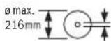
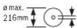
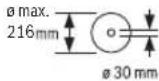
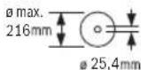
| Saw blade dimensions | Diameter 216 mm, bore 30 mm (or 25.4 mm depending on version) |
| Max cutting width | 3.3 mm |
| Cutting capacity (0°/0°) | Height x Width: 60 x 123 mm |
| Miter angle range (horizontal) | -47° to +47° |
| Bevel angle range (vertical) | 0° to +45° |
| Guide laser | Class 2, < 1 mW, 650 nm |
| Power supply | Single-phase, 230 V (compatible with 220 V) |
| Protection class | II (double insulation) |
| Supplied accessories | Clamp, hex key, extensions, longitudinal stop, dust bag |
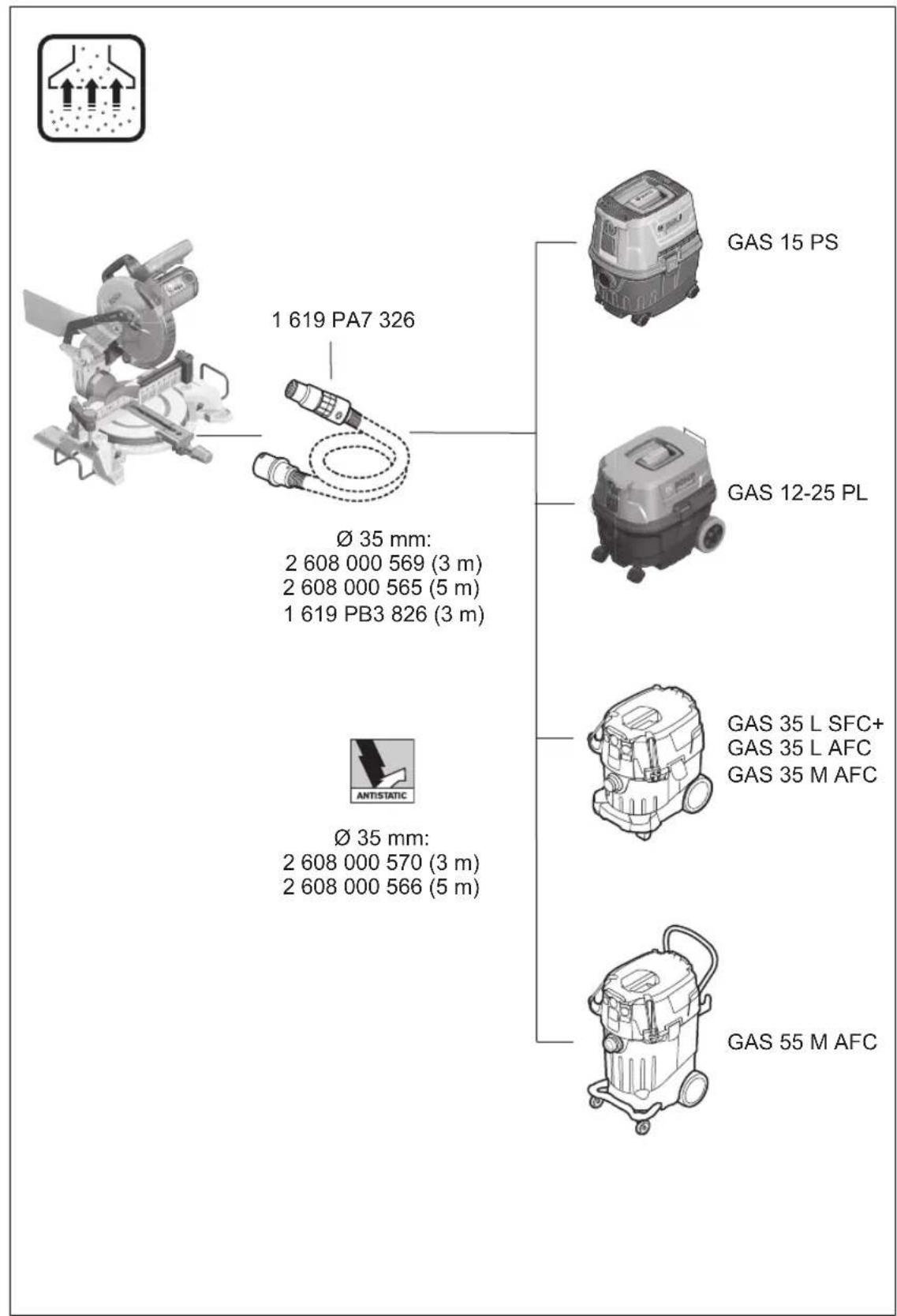
| Dust extraction system | Dust bag (Ø 36 mm) or vacuum cleaner connection |
| Mechanical safety | Pendulum guard, spindle lock, transport safety |
| Compatible materials | Wood, panels, plastics, aluminum (with suitable blade) |
| Minimum workpiece dimensions | 145 x 50 mm (for clamping with supplied clamp) |
| Maintenance | Regular cleaning of the laser lens, rollers, and protective guard |
| Repairability | Spare parts available through Bosch after-sales service, repair by authorized center |
Frequently Asked Questions - GCM 216 Professional BOSCH
User questions about GCM 216 Professional BOSCH
0 question about this device. Answer the ones you know or ask your own.
Ask a new question about this device
Download the instructions for your Saw in PDF format for free! Find your manual GCM 216 Professional - BOSCH and take your electronic device back in hand. On this page are published all the documents necessary for the use of your device. GCM 216 Professional by BOSCH.
USER MANUAL GCM 216 Professional BOSCH
GCM 216 Professional
Robert Bosch Power Tools GmbH
70538 Sollgart
GERMANY
www.bosch-pt.com
160992A72S(2021.11)PS/111

160992A72S
en Original instructions
fr Notice originale
pt Manual original
zh 正本使用说明书
zh原始使用说明
thnnaa
204611
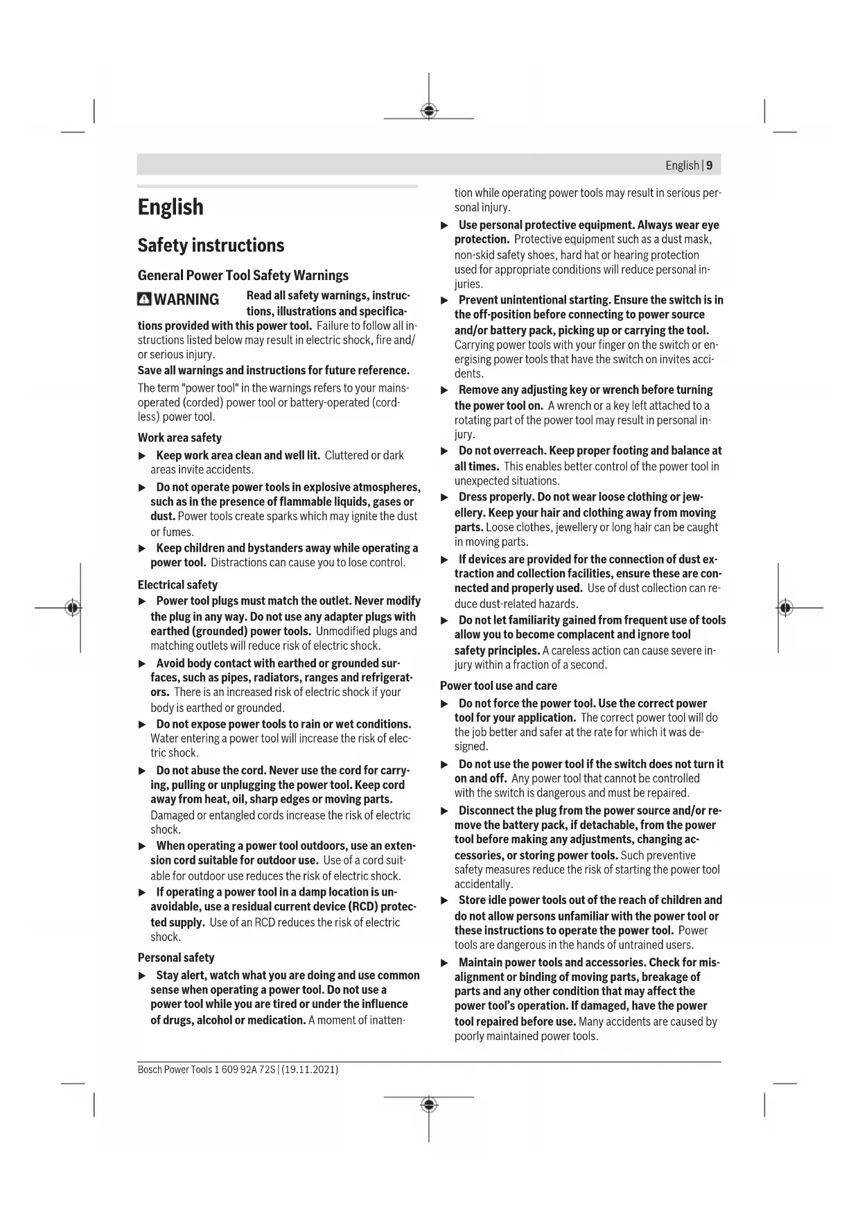
General Power Tool SafetyWarnings
WARNING
Read all safety warnings, instructions, illustrations and specifica
tions provided with this power tool. Failure to follow all instructions listed below may result in electric shock, fire and/ or serious injury.
Save all warnings and instructions for future reference.
The term "power tool" in the warnings refers to your mains-operated (corded) power tool or battery-operated (cordless) power tool.
Work area safety
- Keep work area clean and well lit. Cluttered or dark areas invite accidents.
- Do not operate power tools in explosive atmospheres, such as in the presence of flammable liquids, gases or dust. Power tools create sparks which may ignite the dust or fumes.
- Keep children and bystanders away while operating a power tool. Distractions can cause you to lose control.
Electrical safety
Power tool plugs must match the outlet. Never modify the plug in any way. Do not use any adapter plugs with earthed (grounded) power tools. Unmodified plugs and matching outlets will reduce risk of electric shock.
- Avoid body contact with earthed or grounded surfaces, such as pipes, radiators, ranges and refrigerators. There is an increased risk of electric shock if your body is earthed or grounded.
Do not expose power tools to rain or wet conditions. Water entering a power tool will increase the risk of electric shock.
Do not abuse the cord. Never use the cord for carrying, pulling or unplugging the power tool. Keep cord away from heat, oil, sharp edges or moving parts. Damaged or entangled cords increase the risk of electric shock.
When operating a power tool outdoors, use an extension cord suitable for outdoor use. Use of a cord suitable for outdoor use reduces the risk of electric shock.
If operating a power tool in a damp location is unavoidable, use a residual current device (RCD) protected supply. Use of an RCD reduces the risk of electric shock.
Personal safety
Stay alert, watch what you are doing and use common sense when operating a power tool. Do not use a power tool while you are tired or under the influence of drugs, alcohol or medication. A moment of inatten
tion while operating power tools may result in serious personal injury.
Use personal protective equipment. Always wear eye protection. Protective equipment such as a dust mask, non-skid safety shoes, hard hat or hearing protection used for appropriate conditions will reduce personal injuries.
Prevent unintentional starting. Ensure the switch is in the off-position before connecting to power source and/or battery pack, picking up or carrying the tool. Carrying power tools with your finger on the switch or energising power tools that have the switch on invites accidents.
- Remove any adjusting key or wrench before turning the power tool on. A wrench or a key left attached to a rotating part of the power tool may result in personal injury.
- Do not overreach. Keep proper footing and balance at all times. This enables better control of the power tool in unexpected situations.
Dress properly. Do not wear loose clothing or jewellery. Keep your hair and clothing away from moving parts. Loose clothes, jewellery or long hair can be caught in moving parts.
If devices are provided for the connection of dust extraction and collection facilities, ensure these are connected and properly used. Use of dust collection can reduce dust-related hazards.
Do not let familiarity gained from frequent use of tools allow you to become complacent and ignore tool safety principles. A careless action can cause severe injury within a fraction of a second.
Power tool use and care
Do not force the power tool. Use the correct power tool for your application. The correct power tool will do the job better and safer at the rate for which it was designed.
Do not use the power tool if the switch does not turn it on and off. Any power tool that cannot be controlled with the switch is dangerous and must be repaired.
- Disconnect the plug from the power source and/or remove the battery pack, if detachable, from the power tool before making any adjustments, changing accessories, or storing power tools. Such preventive safety measures reduce the risk of starting the power tool accidentally.
- Store idle power tools out of the reach of children and do not allow persons unfamiliar with the power tool or these instructions to operate the power tool. Power tools are dangerous in the hands of untrained users.
- Maintain power tools and accessories. Check for misalignment or binding of moving parts, breakage of parts and any other condition that may affect the power tool's operation. If damaged, have the power tool repaired before use. Many accidents are caused by poorly maintained power tools.
10 | English
- Keep cutting tools sharp and clean. Properly maintained cutting tools with sharp cutting edges are less likely to bind and are easier to control.
Use the power tool, accessories and tool bits etc. in accordance with these instructions, taking into account the working conditions and the work to be performed. Use of the power tool for operations different from those intended could result in a hazardous situation. - Keep handles and grasping surfaces dry, clean and free from oil and grease. Slippery handles and grasping surfaces do not allow for safe handling and control of the tool in unexpected situations.
Service
Have your power tool serviced by a qualified repair person using only identical replacement parts. This will ensure that the safety of the power tool is maintained.
SafetyWarnings for Mitre Saws
Mitre saws are intended to cut wood or wood-like products, they cannot be used with abrasive cut-off wheels for cutting ferrous material such as bars, rods, studs, etc. Abrasive dust causes moving parts such as the lower guard to jam. Sparks from abrasive cutting will burn the lower guard, the kerf insert and other plastic parts.
Use clamps to support the workpiece whenever possible. If supporting the workpiece by hand, you must always keep your hand at least 100mm from either side of the saw blade. Do not use this saw to cut pieces that are too small to be securely clamped or held by hand. If your hand is placed too close to the saw blade, there is an increased risk of injury from blade contact.
The workpiece must be stationary and clamped or held against both the fence and the table. Do not feed the workpiece into the blade or cut "freehand" in any way. Unrestrained or moving workpieces could be thrown at high speeds, causing injury.
- Push the saw through the workpiece. Do not pull the saw through the workpiece. To make a cut, raise the saw head and pull it out over the workpiece without cutting, start the motor, press the saw head down and push the saw through the workpiece. Cutting on the pull stroke is likely to cause the saw blade to climb on top of the workpiece and violently throw the blade assembly towards the operator.
Never cross your hand over the intended line of cutting either in front or behind the saw blade. Supporting the workpiece "cross handed" i.e. holding the workpiece to the right of the saw blade with your left hand or vice versa is very dangerous.
Do not reach behind the fence with either hand closer than 100mm from either side of the saw blade, to remove wood scraps, or for any other reason while the blade is spinning. The proximity of the spinning saw blade to your hand may not be obvious and you may be seriously injured.
Inspect your workpiece before cutting. If the workpiece is bowed or warped, clamp it with the outside bowed face toward the fence. Always make certain that there is no gap between the workpiece, fence and table along the line of the cut. Bent or warped workpieces can twist or shift and may cause binding on the spinning saw blade while cutting. There should be no nails or foreign objects in the workpiece.
Do not use the saw until the table is clear of all tools, wood scraps, etc., except for the workpiece. Small debris or loose pieces of wood or other objects that contact the revolving blade can be thrown with high speed.
Cut only one workpiece at a time. Stacked multiple workpieces cannot be adequately clamped or braced and may bind on the blade or shift during cutting.
Ensure the litre saw is mounted or placed on a level, firm work surface before use. A level and firm work surface reduces the risk of the litre saw becoming unstable.
Plan your work. Every time you change the bevel or mitre angle setting, make sure the adjustable fence is set correctly to support the workpiece and will not interfere with the blade or the guarding system. Without turning the tool "ON" and with no workpiece on the table, move the saw blade through a complete simulated cut to assure there will be no interference or danger of cutting the fence.
Provide adequate support such as table extensions, saw horses, etc. for a workpiece that is wider or longer than the table top. Workpieces longer or wider than the metre saw table can tip if not securely supported. If the cut-off piece or workpiece tips, it can lift the lower guard or be thrown by the spinning blade.
Do not use another person as a substitute for a table extension or as additional support. Unstable support for the workpiece can cause the blade to bind or the workpiece to shift during the cutting operation pulling you and the helper into the spinning blade.
The cut-off piece must not be jammed or pressed by any means against the spinning saw blade. If confined, i.e. using length stops, the cut-off piece could get wedged against the blade and thrown violently.
Always use a clamp or a fixture designed to properly support round material such as rods or tubing. Rods have a tendency to roll while being cut, causing the blade to "bite" and pull the work with your hand into the blade.
Let the blade reach full speed before contacting the workpiece. This will reduce the risk of the workpiece being thrown.
If the workpiece or blade becomes jammed, turn the litre saw off. Wait for all moving parts to stop and disconnect the plug from the power source and/or remove the battery pack. Then work to free the jammed material. Continued sawing with a jammed workpiece could cause loss of control or damage to the litre saw.
After finishing the cut, release the switch, hold the saw head down and wait for the blade to stop before
removing the cut-off piece. Reaching with your hand near the coasting blade is dangerous.
Hold the handle firmly when making an incomplete cut or when releasing the switch before the saw head is completely in the down position. The braking action of the saw may cause the saw head to be suddenly pulled downward, causing a risk of injury.
Do not let go of the handle once the saw head has reached the lowest position. Always guide the saw head back to the top position by hand. There is a risk of injury if the saw head moves in an uncontrolled manner.
- Keep your work area clean. Material mixtures are particularly hazardous. Light metal dust may catch fire or explode.
Do not use dull, cracked, bent or damaged saw blades. Unsharpened or improperly set saw blades produce narrow kerf causing excessive friction, blade binding and kickback.
Do not use saw blades made from high speed steel (HSS). Such saw blades can easily break.
Always use saw blades with correct size and shape (diamond versus round) of arbour holes. Saw blades that do not match the mounting hardware of the saw will run off-centre, causing loss of control.
- Never remove cuttings, wood chips, etc. from the cutting area while the power tool is running. Always guide the tool arm back to the neutral position first and then switch the power tool off.
Do not touch the saw blade after working before it has cooled. The saw blade becomes very hot while working. Products sold in GB only:
Your product is fitted with an BS 1363/A approved electric plug with internal fuse (ASTA approved to BS 1362). If the plug is not suitable for your socket outlets, it should be cut off and an appropriate plug fitted in its place by an authorised customer service agent. The replacement plug should have the same fuse rating as the original plug. The severed plug must be disposed of to avoid a possible shock hazard and should never be inserted into a mains socket elsewhere.
The power tool is delivered with a laser warning sign (see table:"Symbols and their meaning").
Never make warning signs on the machine unrecognisable.

Do not direct the laser beam at persons or animals and do not stare into the direct or reflected laser beam yourself. You could blind somebody, cause accidents or damage your eyes.
If laser radiation hits your eye, you must close your eyes and immediately turn your head away from the beam.
Do not make any modifications to the laser equipment.
Do not let children use the power tool unsupervised. They could unintentionally blind themselves or other persons
If the text of the laser warning label is not in your national language, stick the provided warning label in your national language over it before operating for the first time.
Symbols
The following symbols may be important for the operation of your power tool. Please take note of these symbols and their meaning. Correctly interpreting the symbols will help you to operate the power tool more effectively and safely.
Symbols and their meaning

Keep hands away from the cutting area while the power tool is running. Contact with the saw blade can lead to injuries.

Wear a dust mask.

Wear safety goggles.

Wear hearing protection. Exposure to noise can cause hearing loss.

Danger area! Keep hands, fingers and arms away from this area.
3601M330..
30mm
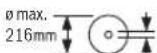
Take note of the dimensions of the saw blade. The hole diameter must match the tool spindle without play. If it is necessary to use reducers, ensure that the dimensions of the reducer are suitable for the base blade thickness and the saw blade hole diameter, as well as the tool spindle diameter. Wherever possible, use the reducers provided with the saw blade.
3601M33080
25.4mm
The saw blade diameter must match the information specified on the symbol.
The adjustable fence must be pulled outwards or removed completely when sawing bevel angles.
Symbols and their meaning

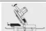
Never carry the power tool using the handle of the tool arm.
Product Description and Specifications

Read all the safety and general instructions.
Failure to observe the safety and general instructions may result in electric shock, fire and/or serious injury.
Please observe the illustrations at the beginning of this operating manual.
Intended Use
The power tool is a stationary machine for cutting in a straight line with and against the grain in hardwood, softwood, chipboard and fibreboard. It is possible to cut metre angles of -47^ to +47^ and bevel angles of 0^ to +45^ .
When using appropriate saw blades, sawing aluminium profiles and plastic is also possible.
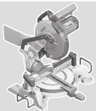
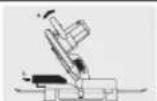
Product Features
The numbering of the product features refers to the diagram of the power tool on the graphics page.
(1) Dust bag
(2) Protective guard
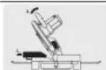
(3) Transport handle
(4) Handle
(5) Lock-off function for on/off switch
(6) Laser warning label
(7) Laser protection cap
(8) Laser beam outlet aperture
(9) Retracting blade guard
(10) Length gauge
(11) Fence
(12) Saw table.
(13) Clamping screw for extension bar
(14) Insert plate.
(15) Locking knob for various metre angles
(16) Mitre pre-setting lever
(17) Angle indicator for metre angles
(18) Scale for mitre angles
(19) Mounting holes
(20) Recessed handles
(21) Extension bar
(22) Screw clamp
(23) Adjustable fence
(24) Scale for bevel angle
(25) Angle indicator (vertical)
(26) Guide roller
(27) Chip deflector
(28) Spindle lock
(29) On/off switch
(30) On/off switch for laser (cutting line indication)
(31) Chip ejector
(32) Hex key
(33) Clamping handle for various bevel angles
(34) Transport safety lock
(35) Holes for screw clamp
(36) Wing bolt for fixing the guide rail for length gauge
(37) Guide rail for length gauge
(38) Securing screw for extension bar
(39) Hex socket screw for mounting the saw blade
(40) Clamping flange
(41) Saw blade
(42) Inner clamping flange
(43) Wing bolt for fixing the adjustable fence
(44) Wing bolt for adjusting the height of the threaded rod
(45) Threaded rod
(46) Clamping screw for length gauge
(47) Screws for insert plate
(48) Hex socket screw for fence
(49) Screw for mitre angle indicator
(50) Knurled screw for laser protection cap
(51) Laser lens cover
Technical Data
Mitre saw GCM 216 GCM 216
| Article number | 3601 M33 0.. | 3601 M33 080 | |
| 3601 M33 0LO | |||
| Rated power input W 1300 1300 | |||
| No-load speed min | -1 | 4800 | 4800 |
| Laser type nm 650 650 | |||
| mW < 1 < 1 |
Mitre saw GCM 216 GCM 216
Laser class 2 2
Divergence of laser line mrad (full angle) 1.0 1.0
Weight according to EPTA-Procedure 01:2014 kg 9.1 9.1
Protection class
□/Ⅱ/Ⅱ
回
Dimensions of suitable saw blades
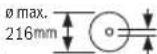
Saw blade diameter mm 216 216
Base blade thickness mm 1.4-1.8 1.4-1.8
Max. cutting width mm 3.3 3.3
Hole diameter mm 30 25.4
Permitted workpiece dimensions (maximum/minimum):
(see "Permissible workpiece dimensions", page 16)
The specifications apply to a rated voltage [U] of 230V . These specifications may vary at different voltages and in country-specific models.
The appliance meets IEC 61000-3-11 requirements and is subject to conditional connection. The appliance can lead to occasional voltage fluctuations under unfavorable power conditions. The impedance of this appliance is set as Z_actual = 0.35 . The user must make sure, that the connection point, with the impedance Z_max , on which the appliance shall be plugged in, meets the impedance requirement: Z_actual ≥ Z_max . If Z_max is unknown, determine Z_max in consultation with the network supplier or supply authority.
Assembly
- Avoid starting the power tool unintentionally. The mains plug must not be connected to the power supply during assembly or when carrying out any kind of work on the power tool.
Items included

See the list of items included at the start of the operating manual.
Check to ensure that all the parts listed below have been supplied before using the power tool for the first time:
- Mitre saw with mounted saw blade
Screw clamp (22) - Hex key (32)
Extension bar (21) with securing screw (38) (2 x)
Length gauge (10)
Dust bag (1)
Note: Check the power tool for possible damage.
Before continuing to use the power tool, carefully check that all protective devices or slightly damaged parts are working perfectly and according to specifications. Check that the moving parts are working perfectly and without jamming; check whether any parts are damaged. All parts must be fitted correctly and all the conditions necessary to ensure smooth operation must be met.
If the protective devices or any parts become damaged, you must have them properly repaired or replaced by an authorised service centre.
Fitting individual components
- Carefully remove all parts included in the delivery from their packaging.
- Remove all packing material from the power tool and the accessories provided.
Fitting the extension bar (see figure A)
The free end of long and heavy workpieces must have something placed underneath it or be supported.
To extend the saw table further, extension bars can be mounted both to the left or right of the power tool.
-
Unscrew the securing screw (38) from the extension bar with a cross-headed screwdriver.
-
Tilt the power tool.
Push the extension bars (21) on both sides of the power tool all the way into the corresponding drill holes. - For the pull-out safety device, screw the securing screw (38) back into the extension bar.
Stationary or flexible mounting
To ensure safe handling, the power tool must be mounted on a flat, stable work surface (e.g. work bench) before use.
Mounting on a work surface (see figure B1-B2)
Use suitable screw fasteners to secure the power tool to the work surface. The holes (19) are used for this purpose.
or
- Firmly clamp the base of the power tool to the work surface with commercially available screw clamps.
14|English
Mounting on a Bosch saw stand
With the height-adjustable legs, Bosch GTA saw stands provide firm support for the power tool on any surface. The workpiece supports of the saw stand are used for underlaying long workpieces.
Read all the warnings and instructions included with the saw stand. Failure to observe the warnings and follow instructions may result in electric shock, fire and/or serious injury.
Assemble the saw stand properly before mounting the power tool. Correct assembly is important to prevent the risk of collapsing.
- Mount the power tool on the saw stand in the transport position.
Dust/Chip Extraction
The dust from materials such as lead paint, some types of wood, minerals and metal can be harmful to human health. Touching or breathing in this dust can trigger allergic reactions and/or cause respiratory illnesses in the user or in people in the near vicinity.
Certain dusts, such as oak or beech dust, are classified as carcinogenic, especially in conjunction with wood treatment additives (chromate, wood preservative). Materials containing asbestos may only be machined by specialists.
- Use a dust extraction system that is suitable for the material wherever possible.
- Provide good ventilation at the workplace.
- It is advisable to wear a P2 filter class breathing mask.
The regulations on the material being machined that apply in the country of use must be observed.
- Avoid dust accumulation at the workplace. Dust can easily ignite.
The dust/chip extraction system can be blocked by dust, chips or fragments of the workpiece.
- Switch the power tool off and pull the mains plug out of the socket.
- Wait until the saw blade has come to a complete stop.
- Determine the cause of the blockage and eliminate it.
Self-generated dust extraction (see figure C)
For basic chip collection, use the dust bag (1) provided.
- Attach the dust bag (1) to the chip ejector (31).
During sawing, the dust bag must not come into contact with moving tool components.
Always empty the dust bag in good time.
Check and clean the dust bag each time after using.
- When sawing aluminium, remove the dust bag to avoid the risk of fire.
External Dust Extraction
You can also attach a dust extraction hose (36 mm diameter) to the chip ejector (31) for extraction.
- Connect the dust extraction hose to the chip ejector (31).
The dust extractor must be suitable for the material being worked.
When extracting dry dust that is especially detrimental to health or carcinogenic, use a special dust extractor.
Changing the saw blade (see figures D1-D3)
Pull the plug out of the socket before carrying out any work on the power tool.
Wear protective gloves when fitting the saw blade. There is a risk of injury when touching the saw blade.
Only use saw blades that have a maximum permitted speed higher than the no-load speed of the power tool.
Only use saw blades that match the specifications given in this operating manual and that have been tested and marked in accordance with EN 847-1.
Only use saw blades that are recommended by the power tool manufacturer and are suitable for use on the material you want to saw. This will prevent the saw teeth overheating when sawing.
Removing the Saw Blade
- Bring the power tool into the work position.
- Swivel the retracting blade guard (9) to the back and hold it in this position.
Turn the hex socket screw (39) with the hex key (6 mm) (32) and at the same time push the spindle lock (28) until it engages. - Keep holding the spindle lock (28) and loosen the hex socket screw (39) by turning it clockwise (left-hand thread).
- Remove the clamping flange (40).
- Remove the saw blade (41).
- Slowly push the retracting blade guard back down.
Fitting the saw blade
- When fitting the saw blade, make sure that the cutting direction of the teeth (arrow direction on the saw blade) matches the direction of the arrow on the protective guard.
If required, clean all the parts you want to fit before installing them.
- Swivel the retracting blade guard (9) to the back and hold it in this position.
- Place the new saw blade on the inner clamping flange (42).
- Fit the clamping flange (40) and the hex socket screw (39). Press the spindle lock (28) until it engages and tighten the hex socket screw by turning it anticlockwise.
- Slowly push the retracting blade guard back down.
Operation
Pull the plug out of the socket before carrying out any work on the power tool.
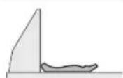
Transport Safety Lock (see figure E)
The transport safety lock (34) makes it easier to handle the power tool when transporting it to various working locations.
Unlocking the power tool (work position)
- Press the tool arm down slightly by the handle (4) to release the transport safety lock (34).
- Pull the transport safety lock (34) all the way out.
- Slowly guide the tool arm upwards.
Locking the power tool (transport position)
- To lock the saw table (12) in place, tighten the locking knob (15).
- Swing the tool arm downwards by the handle (4) until you can press the transport safety lock (34) all the way in.
The tool arm is now securely locked and ready for transportation.
Preparing for operation
Extending the saw table (see figure F)
The free end of long workpieces must have something placed underneath it or be supported.
The saw table can be extended left and right using the extension bar (21).
- Loosen the clamping screw (13).
- Pull out the extension bar (21) to the required length.
- Retighten the clamping screw (13) to fix the extension bar.
Moving the fence (see figure G)
You have to move the adjustable fence (23) to saw bevel angles.
-Loosen the wing bolt (43).
- Pull the adjustable fence (23) all the way out.
- Retighten the wing bolt (43).
After sawing the bevel angles, slide the adjustable fence (23) back again (loosen the wing bolt (43); slide the fence (23) all the way in; retighten the wing bolt).
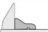
Clamping the workpiece (see figure H)
To ensure maximum safety while working, the workpiece must always be firmly clamped.
Do not saw workpieces that are too small to clamp firmly.
- Press the workpiece firmly against the fences (11) and (23).
- Insert the supplied screw clamp (22) into one of the corresponding holes (35).
- Loosen the wing bolt (44) and adjust the screw clamp to the workpiece. Tighten the wing bolt again.
- Tighten the threaded rod (45) to fix the workpiece in place.
Releasing the workpiece
- To loosen the screw clamp, turn the threaded rod (45) anticlockwise.
Setting mitre and bevel angles
To ensure precise cuts, the basic settings of the power tool must be checked and adjusted as necessary after intensive use.
Experience and suitable special tools are required for this.
A Bosch after-sales service point will handle this work quickly and reliably.
Always tighten the locking knob (15) and the clamping handle (33) firmly before sawing. Otherwise the saw blade can become wedged in the workpiece.
Adjusting litre angles (see figure I)
The mitre angle can be set between 47^ (left side) and 47^ (right side).
- Loosen the locking knob (15) if it is tightened.
- Pull the lever (16) upwards, turn the saw table (12) left or right by the locking knob and set the required metre angle using the angle indicator (17).
- Retighten the locking knob (15).
For quick and precise setting of commonly used mitre angles, detents are provided on the saw table:
Left Right
0°
45^;30^;22.5^;15^15^;22.5^;30^;45^
- Loosen the locking knob (15) if it is tightened.
- Pull the lever (16) and rotate the saw table (12) left or right to the required detent.
- Release the lever again. The lever must be felt to engage in the detent.
- Retighten the locking knob (15).
Setting Bevel Angles (see figure J)
The bevel angle can be set between 0^ and 45^ .
- Pull the adjustable fence (23) all the way out.
- Loosen the clamping handle (33).
- Use the handle (4) to swivel the tool arm until the angle indicator (25) shows the required bevel angle.
- Hold the tool arm in this position and retighten the clamping handle (33).
End stops are provided on the housing that enable the standard angles of 0^ and 45^ to be set quickly and accurately.
Start-up
▶ Products that are only sold in AUS and NZ: Use a residual current device (RCD) with a nominal residual current of 30 mA or less.
Pay attention to the mains voltage. The voltage of the power source must match the voltage specified on the rating plate of the power tool.
Pay attention to the mains voltage. The voltage of the power source must match the voltage specified on the rating plate of the power tool. Power tools marked with 230V can also be operated with 220V .
Switching on (see figure K)
- To switch on the power tool, first slide the lock-off button (5) to the middle and then press and hold the on/off switch (29).
Note: For safety reasons, the on/off switch (29) cannot be locked; it must remain pressed during the entire operation.
16|English
Switching off
-To switch off, release the on/off switch (29).
Sawing
General sawing instructions
Always tighten the locking knob (15) and the clamping handle (33) firmly before sawing. Otherwise the saw blade can become wedged in the workpiece.
For all cuts, it must first be ensured that the saw blade at no time can come in contact with the fence, screw clamps or other machine parts. Remove any mounted auxiliary stops or adjust them accordingly.
Protect the saw blade against impact and shock. Do not subject the saw blade to lateral pressure.
Only saw materials which are permitted within the scope of the intended use.
Do not saw warped/bent workpieces. The workpiece must always have a straight edge to face against the fence.
The free end of long and heavy workpieces must have something placed underneath it or be supported.
Make sure that the retracting blade guard operates properly and that it can move freely. The retracting blade guard must open when the tool arm is guided downwards. When the tool arm is guided upwards, the retracting blade guard must close again over the saw blade and lock in the uppermost position of the tool arm.
Position of the operator (see figure L)
Do not stand in line with the saw blade in front of the power tool. Always stand to the side of the saw blade.
This protects your body against possible kickback.
- Keep hands, fingers and arms away from the rotating saw blade.
- Do not reach one hand across the other when in front of the tool arm.
Sawing (cutting)
- Firmly clamp the workpiece as appropriate for its dimensions.
- Set the required metre and/or bevel angle. When sawing metre angles from left to right, you must pull the length stop (10) all the way out or remove it completely.
- Switch on the power tool.
- Slowly guide the tool arm downwards using the handle (4).
- Saw through the workpiece applying uniform feed.
- Switch off the power tool and wait until the saw blade (41) has come to a complete stop.
- Slowly guide the tool arm upwards.
Practical advice
Marking the Cutting Line (see figure M)
A laser beam shows you the cutting line of the saw blade. This allows for exact positioning of the workpiece for sawing, without having to open the retracting blade guard.
- To activate this, turn on the laser beam using the switch (30).
- Align your mark on the workpiece with the right-hand edge of the laser line.
Note: Before sawing, check whether the cutting line is still indicated correctly. The laser beam can be misaligned due to vibrations from intensive use, for example.
Permissible workpiece dimensions
Maximum workpiece dimensions:
Mitre angle Bevel angle Height x width
[mm]
0^0^60× 123
0^45^43× 123
45^ (left/right) 0^ 60 × 80
45^ (left) 45^ 43 × 80
45^ (right) 45^35 × 80
Minimum workpiece dimensions ( = all workpieces that can be secured left or right of the saw blade using the supplied screw clamps (22)): 145 x 50 mm (length x width)
Maximum cutting depth (0^ / 0^) .. 60mm
Sawing workpieces of the same length (see figure N)
The length gauge (10) can be used for easily sawing workpieces of the same length.
- Loosen the clamping screw (46) and move the length gauge (10) in the guide rail (37) to the required workpiece length.
- Retighten the clamping screw (46).
Longer workpieces: - Loosen the wing bolt (36) and pull out the guide rail (37) as far as it will go.
- Retighten the wing bolt (36).
- Adjust the length gauge (10) to the required workpiece length.
Sawing without a length gauge: - Loosen the clamping screw (46) and move the length gauge (10) in the guide rail (37) all the way out.
- Rotate the length gauge by 90^ until it is flush with the fence (11).
- Retighten the clamping screw (46).
Special workpieces
When sawing curved or round workpieces, these must be especially secured against slipping. At the cutting line, there should be no gap between the workpiece, fence and saw table.
If necessary, you will need to manufacture special fixtures.
Replacing insert plates (see figure 0)
The insert plate (14) can become worn after long use of the power tool.
Replace faulty insert plates.
- Bring the power tool into the work position.
- Unscrew the screws (47) using a commercially available cross-headed screwdriver and remove the old insert plate (14).
- Insert the new insert plate and screw the screws (47) in tight again.
Working on mouldings
Mouldings can be sawn in two different ways:
| Positioning of workpiece | Base moulding Crown moulding |
| - Placed against the fence | |
| -Lying flat on the saw table |
Always check the set litre and/or bevel angle first by making trial cuts in scrap wood.
Checking and Adjusting the Basic Settings
To ensure precise cuts, the basic settings of the power tool must be checked and adjusted as necessary after intensive use.
Experience and suitable special tools are required for this.
A Bosch after-sales service point will handle this work quickly and reliably.
Aligning the fence
- Bring the power tool into the transport position.
- Turn the saw table (12) to the 0^ detent. The lever (16) must be felt to engage in the detent.
- Pull the adjustable fence (23) all the way out.
Checking (see figure P1)
- Set an angle gauge to 90^ and position it flush with the saw blade (41) between the fence (11) and the saw blade on the saw table (12).
The leg of the angle gauge must be flush with the fence over the complete length.
Setting (see figure P2)
- Loosen all hex socket screws (48) with the hex key (32) provided.
- Rotate the fence (11) until the angle gauge is flush over the complete length.
- Re-tighten the screws.
Aligning the mitre angle indicator (see figure Q)
- Bring the power tool into the work position.
- Turn the saw table (12) to the 0^ detent. The lever (16) must be felt to engage in the detent.
Checking
The angle indicator(17) must be in line with the 0^ mark of the scale (18).
Setting
- Loosen the screw (49) using a cross-headed screwdriver and align the angle indicator along the 0^ mark.
- Retighten the screw.
Transport (see figure R)
Before transporting the power tool, the following steps must be carried out:
- Bring the power tool into the transport position.
- Remove all accessories that cannot be securely fitted to the power tool.
If possible, transport unused saw blades in a closed container.
- Carry the power tool by the transport handle (3) or hold it by the recessed handles (20) on the sides of the saw table.
Only use the transport devices to transport the power tool and never the protective devices.
Maintenance and Service
Maintenance and Cleaning
Pull the plug out of the socket before carrying out any work on the power tool.
To ensure safe and efficient operation, always keep the power tool and the ventilation slots clean.
In order to avoid safety hazards, if the power supply cord needs to be replaced, this must be done by Bosch or by an after-sales service centre that is authorised to repair Bosch power tools.
The retracting blade guard must always be able to move freely and retract automatically. It is therefore important to keep the area around the retracting blade guard clean at all times.
Always remove dust and chips after working by blowing out with compressed air or using a brush.
Clean the guide roller (26) regularly.
Cleaning the laser lens (see figure S)
- Swivel the retracting blade guard (9) to the back and hold it in this position.
- Loosen the knurled screw (50) for the laser protection cap (7).
- Pull the clear laser lens cover (51) forwards and out of the laser protection cap and wipe off any dirt using a dry, soft cloth.
- Reinsert the cover (51) in the laser protection cap as far as it will go (7) and retighten the knurled screw (50).
Accessories
| Article number | |
| Extension bar 1619 PB6 147 | |
| Dust bag 1619 PB6 246 | |
| Reducing ring 30/25.4 x 1.2 mm 2 600 100 211 | |
Article number
Saw blades for wood and fibreboard, panels and strips
216 x 30 mm saw blade, 48 teeth 2 608 640 432
Saw blades for plastic and non-ferrous metals
216 x 30 mm saw blade, 60 teeth 2 608 640 446
Saw blades for all types of laminate flooring
216 x 30 mm saw blade, 60 teeth 2608642 133
After-Sales Service and Application Service
Our after-sales service responds to your questions concerning maintenance and repair of your product as well as spare parts. You can find explosion drawings and information on spare parts at: www.bosch-pt.com
The Bosch product use advice team will be happy to help you with any questions about our products and their accessories.
In all correspondence and spare parts orders, please always include the 10-digit article number given on the nameplate of the product.
Malaysia
Robert Bosch Sdn. Bhd.(220975-V) PT/SMY
No.8A,Jalan 13/6
46200 Petaling Jaya
Selangor
Tel.: (03) 79663194
Toll-Free: 1800 880188
Fax: (03) 79583838
E-Mail: kiathoe.chong@my.bosch.com
www.bosch-pt.com.my
You can find further service addresses at:
www.bosch-pt.com/serviceaddresses
Disposal
The power tool, accessories and packaging should be recycled in an environmentally friendly manner.
Do not dispose of power tools along with household waste.
Français
Transport (voir figure R)
Robert Bosch Morocco SARL
53, Rue Lieutenant Mahmoud Mohamed
20300 Casablanca
Tel.: +212 5 29 31 43 27
E-Mail: sav.outillage@ma.bosch.com
www.bosch-pt.com/serviceaddresses
www.bosch-pt.com/serviceaddresses
处理废弃物
www.bosch-pt.com/serviceaddresses
廢棄物處理
yuaanuuaaunnuuauauauauauauauauauauauauauauauauauauauauauauauauauauauauauauauauauauuu
m
aalwannnnaanrnnnnae aannnnnnaaennnnaaennnnaaennnnaaennnnaaennnnaaennnnaaennnnaaennnnaaennnnaaennnnaaennnnaaennnnaaennnnaaennnnaaennnnaaennnnaaennnnaaennnnaaennnnaaennnnaaennnnaaennnnaaennnnaaennnnaaennnnaaannnnaaannnnaaannnnaaannnnaaannnnaaannnnaaannnnaaannnnaaannnnaaannnnaaannnnaaannnnaaannnnaaannnnaaannnnaaannnnaaannnnaaannnnaaannnnaaannnnaaannnnaaannnnaaannnnaaannnnaaannnnaaennnnaaannnnaaannnnaaannnnaaannnnaaannnnaaannnnaaannnnaaann
1
1 1 1 1 1 1 1 1 1 1 1 1 1 1 1 1 1 1 1 1 1 1 1 1 1 1 1 1 1 1 1 1 1 1 1 1 1 1 1 1 1 1
nnuuululalunauauuunnuuunlunuunnuuunnuuunnuuunnuuunnuuunnuuunnuuunnuuunnuuunnuuunnuuunnuuunnuuunnuuunnuuunnuuunnuuunnuuunnuuunnuuunnuuunnuuunnuuunnuuunnuuunnuuunnuuunnuuunnuuunnuuunnuuunnuuunnuuunnu
nnaa nnnnnae nnne nnnnnae nnnnnae nnnnnae nnnnnae nnnnnae nnnnnae nnnnnae nnnnnae nnnnnae nnnnnae nnnnnae nnnnnae nnnnnae nnnnnae nnnnnae nnnnnae nnnnnae nnnnnae nnnnnae nnnnnae nnnnnaee
A 100000000000000000000000000000000000000000000000000000000000000000000
aunnnnnaannnnnnaanennnnaanennnnaanennnnaanennnnaanennnnaanennnnaanennnnaanennnnaanennnnaanennnnaanennnnaanennnnaanennnnaanennnnaanennnnaanennnnaanennnnaanennnnaanennnnaanennnnaanennnnaanennnnaanennnnaanennnnaanannnnaanannnnaanannnnaanannnnaanannnnaanannnnaanannnnaanannnnaanannnnaanannnnaanannnnaanannnnaanannnnaanann
yunuunununnuunununununununununununununununununununununununununununununununununununununun
58|m
nunnnnnnuuuvnuuauuunnuuuaannu nannnnnnnnnnnnnnnnnnnnnnnnnnnnnnnnnnnnnnnnnnnnnnnnnnnnnnnnnnnnnnnnnnnnnnnnnnnnnnnnnnnnnnnnnnnnnnnnnnnnnnnnnnnnnnnnnnnnnnnnnnnnnnnnnnnnnnnnnnnnnn
Tnannnnnnnnnnnnnnnnnnnnnnnnnnnnnnnnnnnnnnnnnnnnnnnnnnnnnnnnnnnnnnnnnnnnnnnnnnnnnnnnnnnnnnnnnnnnnnnnnnnnnnnnnnnnnnnnnnnnnnnnnnnnnnnnnnnnnnnnnnnnnnnnnnnnnnnnnnnnnnnnnnnnnnnnnnn nn nannn nn nannn nn nannn nn nannn nn nannn nn nannn nn nannn nn nannn nn nannn nn nannn nn nannn nn nannn nn nannn nn nannn nn nannn nn nannn nn nannn nn nannn nn nannn nn nannn nn nannn nn nannn nn nannn nn nannn nn nannn nn nennn nn nannn nn nannn nn nannn nn nannn nn nannn nn nannn nn nannn nn nannn nn nannn nn nannn nn nannn nn nannn nn nannn nn nannn nn nannn nn nannn nn nannn nn nannn nn nannn nn nannn nn nannn nn nannn nn nannn nn nannn nn n ann
1 1 1 1 1 1 1 1 1 1 1 1 1 1 1 1 1 1 1 1 1 1 1 1 1 1 1 1 1 1 1 1 1 1 1 1 1 1
nunnuuunnuunnuunnuunnuunnuunnuunnuunnuunnuunnuunnuunnuunnuunnuunnuunnuunnuunnuunnuunnu
nauuunnnnnaaannnnnnnnnnnnnnnnnnnnnnnnnnnnnnnnnnnnnnnnnnnnnnnnnnnnnnnnnnnnnnnnnnnnnnnnnnnnnnnnnnnnnnnnnnnnnnnnnnnnnnnnnnnnnnnnnnnnnnnnnnnnnnnnnnnnnn
yannnnn nn nnnnnnnnnnnnnnnnnnnnnnnnnnnnnnnnnnnnnnnnnnnnnnnnnnnnnnnnnnnnnnnnnnnnnnnnnnnnnnnnnnnnnnnnnnnnnnnnnnnnnnnnnnnnnnnnnnnnnnnnnnnnnnnnnnnnnnnnnnnnnnnnnnnnnnnn nn
nnnnnnnnnnnnnnnnnnnnnnnnnnnnnnnnnnnnnnnnnnnnnnnnnnnnnnnnnnnnnnnnnnnnnnnnnnnnnnnnnnnnnnnnnnnnnnnnnnnnnnnnnnnnnnnnnnnnnnnnnnnnnnnnn
yauanuunnuuunnuuunnuuunnuuunnuunnuunnuunnuunnuunnuunnuunnuunnuunnuunnuunnuunnuunnuunnuunnuunnuunnuunnuunnuunnuunnuunnuunnuunnuunnuunnuunnuunnuunnu
Buaaannnanaanrnuuulnuuunwagnnnae nulauanrnanrnuuunruuunrnu
n. u. 1u 1u 1u 1u 1u 1u 1u 1u 1u 1u 1u 1u 1u 1u 1u 1u 1u 1u 1u 1u 1u 1u 1u 1u 1u 1u 1u 1u 1u 1u 1u
nauu nnu nnu nnu uunnnnna nnuu uuuu uuuu uuuu uuuu uuuu uuuu uuuu uuuu uuuu uuuu uuuu uuuu uuuu uuuu uuuu uuuu uuuu uuuu uuuu uuuu uuuu uuuu uuuu uuuu uuuu uuuu uuuu uuuu uuuu uuuu uuuu uuuu uuuu uuu uuuu uuuu uuuu uuuu uuuu uuuu uuuu uuuu uuuu uuuu uuuu uuuu uuuu uuuu uuuu uuuu uuuu uuuu uuuu uuuu uuuu uuuu uuuu uuuu uuuu uuuu uuuu uuuu uuuu uuuu uuuu
Jauuuiuuiuuiuuiuuiuuiuuiuuiuuiuuiuuiuuiuuiuuiuuiuuiuuiuuiuuiuuiuuiuuiuuiuuiuuiuuiuuiuuiuuiuuiuuiuuiuuiuuiuuiuuiuuiuuiuuiuuiuuiuuiuuiuuiuuiuuiuuiuuiuuiuuiu
nunnuuunnuuunnuunnuunnuunnuunnuunnuunnuunnuunnuunnuunnuunnuunnuunnuunnuunnuunnuunnuunnuunnuunnuunnuunnuunnuunnuunnuunnuunnuunnuunnuunnuunnuunnuunnuunnuunnuunnu
aannnnnnaan nnnnnnnnnnnnnnnnnnnnnnnnnnnnnnnnnnnnnnnnnnnnnnnnnnnnnnnnnnnnnnnnnnnnnnnnnnnnnnnnnnnnnnnnnnnnnnnnnnnnnnnnnnnnnnnnnnnnnnnnnnnnnnnnnnnnnnnnnnnnnnnnnn nn nannnannnannn nannnannnannn annn nannnannnannn nannnannnannn nannnannnannn nannnannnannn nannnannnannn nannnannn nannnannn nannnannn nannnannn nannnannn nannnannn nannnannn nannnannn nannnannn nannnannn nannnannn nannnannn nannnannn nannnannn nannnannn nannnann
yauuunnnnununununununununununununununununununununununununununununununununununununununununununununununununununununununununun
H
1
yueuuyueyuanyue yuyuyue yuyue uouuyuyuyuyuyuyuyuyuyuyuyuyuyuyuyuyuyuyuyuyuyuyuyuyuyuyuyuyuyuyuyuyuyuyuyuyuyuyuyuyuyuyuyuyuyuyuyuyuyuyuyuyuyuyuyuyuyuyuyuyuyuyuy
Speed Steel, HSS)
1nnaaannnnnnaa (nnnnnnnnnnnnnnnnnnnnnnnnnnnnnnnnnnnnnnnnnnnnnnnnnnnnnnnnnnnnnnnnnnnnnnnnnnnnnnnnnnnnnnnnnnnnnnnnnnnnnnnnnnnnnnnnnnnnnnnnnnnnnnnnnnnnnn
nannnnnnnnnnnnnnnnnnnnnnnnnnnnnnnnnnnnnnnnnnnnnnnnnnnnnnnnnnnnnnnnnnnnnnnnnnnnnnnnnnnnnnnnnnnnnnnnnnnnnnnnnnnnnnnnnnnnnnnnnnnnnnnnnnnnnnnnnnnnnnnnnnnnnnnnnnnnnnn nn
aannnnnnae aennnnne nnnnne
1 1
aannnnnnaeennnnnne aen nnnn

aauvaunuaiauulvauunnaaauauauauauauauauauauauauauauauauauauauauauauauauauauauau
aannnnnnaeennnnne nnnnnnnnnnnnnn
aannnnnnaanennn nnnnnnne
aunnnn nannnnaanennnnnnae
nwnnnnnaaannnnnnnnnnnnnnnnnnnnnnnnnnnnnnnnnnnnnnnnnnnnnnnnnnnnnnnnnnnnnnnnnnnnnnnnnnnnnnnnnnnnnnnnnnnnnnnnnnnnnnnnnnnnnnnnnnnnnnnnnnnnnn
aannn
yannnnaa lnuuunnnnne nnnnnaeauwau wnuu uananaan anananaan aannnnaa nnnnnaa annnnnnaaannnnaaannnnaaannnnaaannnnaaannnnaaannnnaaannnnaaannnnaaannnnaaannnnaaannnnaaannnnaaannnnaaannnnaaannnnaaannnnaaannnnaaannnnaaannnnaaannnnaaannnnaaannnnaaannnnaaannnnaaannnnaa annnnnnnnnnnnnnnnnnnnnnnnnnnnnnnnnnnnnnnnnnnnnnnnnnnnnnnnnnnnnnnnnnnnnnnnnnnnnnnnnnnnnnnnnnnnnnnnnnnnnnnnnnnn
yannnnaaanrnnnnae

y

aannnnnne

y

aannnnnnae annnne nnnnne
aayaaanannnnnnae aen

wnnnnnae! 1000 w
3601 M330.
aannnnnnaananaananaananaananaananaananaananaananaananaananaananaananaananaananaananaananaananaananaananaananaananaananaananaananaananaananaananaananaananaananaananaananaananaananaananaananaananaananaananaananaananaananaananaananaananaananaananaananaananaananaanaraannnnaannnnaannnnaannnnaannnnaannnnaannnnaannnnaannnnaannnnaannnnaannnnaannnnaannnnaannnnaannnnaannnnaannnnaannnnaannnnaannnnaannnnaannnnaannnnaannnnaannnnaannnnaannnnaannnnaannnnaannnnaannnnaannnnaannnnaennnnaannnnaannnnaannnnaannnnaannnnaannnnaannnnaannnnaannnnaannnnaannnnaannnnaannnnaannnnaannnnaannnnaannnnaann
3601 M330 80
yuaanranaa
d

y
yua:duanannnnaa
777

aannnnnnaanennnnnnaaannnnnnaaannnnnnaaannnnnnaaannnnnnaaannnnnnaaannnnnnaaannnnnnaaannnnnnaaannnnnnaaannnnnnaaannnnnnaaannnnnnaaannnnnnaaannnnnnaaannnnnnaaannnnnnaaannnnnnaaannnnnnaaannnnnnaaannnnnnaa annnnnnnnnnnnnnnnnnnnnnnnnnnnnnnnnnnnnnnnnnnnnnnnnnnnnnnnnnnnnnnnnnnnnnnn
nunnnnnae nannnnnnnnnnnnnnnnn
山
wWnWuWuWuWuWuWuWuWuWuWuWuWuWuWuWuWuWuWuWuWuWuWuWuWuWuWuWuWuWuWuWuWuWuWuWuWuWuWuWuWuWuWuWuWuWuWuWuWuWuWuWwUwUwUwUwUwUwUwUwUwUwUwUwUwUwUwUwUwUwUwUwUwUwUwUwUwUwUwUwUwUwUwUwUwUwUwUwUwUwUwUwUwUwUwUwUwUwUwUwUwUw
n
1
60|m
nwnnnn
1
(1)
(2) m
(3)
(4)
(5)
(6)
(7)
(8)
(9) nuiuuluaauiuui
(10)
(11) uwnu
(12)
(13)
(14)
(15)
(16) nuiuunue (nuua)
(17)
(18) wannnnnnaaennnnnnnnnn (nuuun)
(19)
(20)
(21)
(22)
(23)
(24)
(25)
(26)
(27)
(28)
(29)
(30)
(31)
(32)
(33)
(34)
(35)
(36)
(37)
(38)
(39) ananunnnaaannnnnau
(40) nnuua
(41)
(42) nuuuaaonenu
(43)
(44)
(45) mnnnna
(46)
(47)
(48)
(49)
(50)
(51)
yoyantvina
| ### | GCM 216 GCM 216 | |
| ### | 3 601 M33 0.. | 3 601 M33 080 3 601 M33 0LO |
| ### | 1300 1300 | |
| ### | min-1 | 4800 4800 |
| ### | ### | 650 650 |
| ### | < 1 < 1 | |
| ### | 2 | |
| ### | mrad (###) | 1.0 1.0 |
m|61
| ### | GCM 216 | GCM 216 |
| ### EPTA-Procedure 01:2014 | ###.9.19.1 | |
| ### | ###/###/### | |
| ### | ### | |
| ### | ### | |
| ### | ### | |
| ### | ### | |
| ### | ### | |
| ### | ### | |
| ### | ### |
nnuuunnuuunnuuunnuuunnuuuu uuuuuu uuuuuuuuuuuuuuuuuuuuuuuuuuuuuuuuuuuuuuuuuuuuuuuuuuuuuuuuuuuuuuuuuuuuuuuuuuuuuuuuuuuuuuuuuuuuuuuuuuuuuuuuuuuuuuuuuuuuuuuuuuuuuuuuuuuuuuuuuuuuuuuuuuuuuuuuuuuuuuuuuuuuuuuuuuuuuuuuuuuuuuuuuuuuuUU
y
nnaaannnnnnaaannnnnnaa
-777777777777777
nwnwunwunwun (wnwnau A)
y
-(38)
62|m
-1nnaannnnn (21) nnnnnnnnnnnnnnnnnnnnnnnnnnnnnnnnnnnnnnnnnnnnnnnnnnnnnnnnnnnnnnnnnnnnnnnnnnnnnnnnnnnnnnnnnnnnnnnnnnnnnnnnnnnnnnnnnnnnnnnnnnnnnnnnnnn
- wouuunuluiuuaanlueang uang (38)
nnaaannnnnnnnnnnnnnnnnnnnnnnnnn
nnaaannnnnnae (34) nnaananaananaananaananaananaananaananaananaananaananaananaananaananaananaananaananaananaananaananaananaananaananaananaananaananaananaananaananaananaananaananaananaananaananaananaananaananaananaananaananaananaananaananaananaananaananaananaananaananaananaanara
muaaia (anunnuu)
-(4)(34)
一(34)
-
nnae (nnnuuun)
WJHIN: 120000000000000000000000000000000000000000000000000000000000000000000
1
-(29)
d
nunnnnnnnnnnnnnnnnnnnnnnnnnnnnnnnnnnnnnnnnnnnnnnnnnnnnnnnnnnnnnnnnnnnnnnnnnnnnnnnnnnnnnnnnnnnnnnnnnnnnnnnnn
Jugn (15) uanwau (33) wuuu nnuaa
aunnnnnae nnneanennnnn nnnnnn nnnnnn nnnnnn nnnnnn nnnnnn nnnnnn nnnnnn nnnnnn nnnnnn nnnnnn nnnnnn nnnnnn nnnnnn nnnnnn nnnnnn nnnnnn nnnnnn nnnnnn nnnnnn nnnnnn nnnnnn nnnnnn nannnnn nannnnn nannnnn nannnnn nannnnn nannnnn nannnnn nannnnn nannnnn nannnnn nannnnn nannnnn nannnnn nannnnn nannnnn nannnnn nannnnn nannnnn nannnnn nannnnn nannnnn nannnnn nannnnn nannnnn nannnnn nennnnn nannnnn nannnnn nannnnn nannnnn nannnnn nannnnn nannnnn nannnnn nannnnn nannnnn nannnnn nannnnn nannnnn nannnnn nannnnn nann
yuluulunnnnnaaannn
aannnnae annnnnnae annnnae annnnnnae
y
四点共圆, x = 1,y = 2
nnuuunnuuunnuunnnnnnnnnnnnnnnnnnnnnnnnnnnnnnnnnnnnnnnnnnnnnnnnnnnnnnnnnnnnnnnnnnnnnnnnnnnnnnnnnnnnnnnnnnnnnnnnnnnnnnnnnnnnnnnnnnnnnnnnnnnnnnnnnnnnnnnnnnnnnnnnnnnnnnnnnnnnnnn
annnuovnauov (gnwunnuu L)
aunnnnnaanannnnnnnnnnnnnnnnnnnnnnnnnnnnnnnnnnnnnnnnnnnnnnnnnnnnnnnnnnnnnnnnnnnnnnnnnnnnnnnnnnnnnnnnnnnnnnnnnnnnnnnnnnnnnnnnnnnnnnnnnnnnnnnnnnnnnnnn
nannnnnnaa nnnnnae
-10n 1uuaaunnnnnnnnnnnnnnnnn
一
mou (nunnn)
| yujidovlunru | yujidovlunru | x n v [uu.] |
| n v |
0^ 0^ 60 × 123
0^45^43× 123
45^(网) / (网)0^60× 80
45^ (1978) 45^ 43 × 80
45^(m) 45^35× 80
ywnnnnna ( = 2nuynnnnnnnnnnnnnn nn nnnnnnnnnnnnnnnnnnnnnnnnnnnnnnnnnnnnnnnnnnnnnnnnnnnnnnnnnnnnnnnnnnnnnnnnnnnnnnnnnnnnnnnnnnnnnnnnnnnnnnnnnnnnnnnnnnnnnnnnnnnnnnnnnnnnn
nannnnnnnnn (0°/0°): 60 m.
nntaee (nnae N)
nennnnnnnnnnnnnnnnn (10) nannnnnnnnnnnnn
Keselamatan personnel
Menggergaji (memotong)
Palma Tower 10th Floor
Jalan RA Kartini II-S Kaveling 6
Pondok Pinang, Kebayoran Lama
www.bosch-pt.com/serviceaddresses
Caramembuang
Thao Khoa May (Vi Tri Hoat Dong)
- An nhe dung cu xuong o vi tri tay nam (4) de nha khoa an toan dung khi di chuyen (34).
-Kéo khoa an toan dung khi di chuyen (34) hoin toan roi ra ngoai.
-Nhac tay may let tu tu.
Bao Vé An Toàn May (Vi Trí Di Chuyen)
- De khoa bān cua (12), Siét chat vit khoa (15).
-Hay quay tay may xuong bang tay nam (4) cho den khi khoa an toan dung de di chuyen (34) duoc an haoan vaostrong.
Can may luc nay da duoc khoa an toan lai de chuyen van.
Chuan Bi cho su' Hoat Dong
www.bosch-pt.com/serviceaddresses
Su thai bo
Jai jia Jai jia Jai jia Jai jia Jai jia Jai jia Jai jia Jai jia Jai jia Jai jia Jai jia Jai jia Jai jia Jai jia Jai jia Jai jia Jai jia Jai jia Jai jia Jai jia Jai jia Jai jia Jai jia Jai jia Jai jia Jai jia
gall g aolal jswll abg 1
agil g awgao lswll abg cls 1
ugall lall pssw lqbaa p
pcn loa slig .aaol ojlu agll
sallg lswll abg n ogg 99g
glb g balt bs lg bc glblg
ggl g jnn nn kay agilall gl aaioll
lgl jnl jiaoi jaw as ae I q wuu
gl molw ay liu ngk y gabll
. jswll abg g ajc plw
g a g 111111111111111111111111111111111111111111
jg bag aagabg j 2aaii o y dai jw g g j 9 w g g g g g g g g g g g g g g g g g g g
goggl juullljuao n 5u .Jauw21 Jguguagabw Jno Jlalwlg gwaall Jaal glawd .Juwll Juaio uljip
Jusill elioo jcb lc pssll ssoil
jIJI I bU 1g gU Ug Ug Ug Ug Ug
g/9
jIJIooJUaJg
Jgaoo c S_u auiJgSJI
aabjy jssj y bai 8. JlabjI gliio ic |sui lqoi siw!
Ll 100g l qssll
j0o10saiw a u o baauiy
.0u g uai
UkuiIaIJIg
aJ aJo aJooJI JQJ
aJJI Jc aasuaa u g pUw LkWg oJgwsO 1jaiu CIL U lo aaggdoJI AaoL Wg jgda
aJgJJI aJUJI Jj
JLJI JI 15
gJl j
aill 0slal gabll glgul sball ssc n lgsuog uJUuuiu
4.öslag abj gbi
LgJ.0aJlI 10g.1 J 100000000000000000000000000000000000000000000000000
g gllg a 1
gagglg jll no aallag adabig agla Jnssu 2aaljll clllalw g nll 100 100 0000000000000000000000000000000000000
do
auiuJcI.
gJlsswIg jssssll Jlaal abwIg
JaaJl JlaJI lc abgJal Jj JlaJI UoI
Jn Jn Jn Jn Jn Jn
gI Uaia gboai
Jg y8 g uaiyIg auiuI IaiaI
gabla gbaI golgolauu
jauuugn uuaal jao slgall
agagaaaal
aIglll aJzalal Jzalal Jzalal Jzalal Jzalal Jzalal Jzalal Jzalal Jzalal Jzalal Jzalal Jzalal Jzalal Jzalal Jzalal Jzalal Jzalal Jzalal Jzalal Jzalal Jzalal Jzalal Jzalal Jzalal Jzalal Jzalal
1u 100
J 1 J 1 J 1 J 1 J 1 J 1 J 1 J 1 J 1 J 1 J 1 J 1 J 1 J 1 J 1 J 1 J 1 J 1 J 1 J 1 J 1 J 1 J 1 J 1 J 1 J 1 J 1 J 1 J 1 J 1 J 1 J 1 J 1 J 1 J
m = 311 ;
JELIJI LALI JG GOGO JU JUJU
4wjJgogSic 5
1g aaiI aog
Jl 1
1 1 1 1 1 1 1 1 1 1 1 1 1 1 1 1 1 1 1 1 1 1 1 1 1 1 1 1 1 1 1 1

JUgJ JJJ 100000000000000000000000000000000000000000
yaaai Jlss
y j 100000000000000000000000000000000000000000000000000000000000
- 1gj jai jilaoaui gj jgi jaiu jilao uaiu gjgl sic jdlug qiaolal aannn jgj .dall juaill
jgaaJI|JzKl
oJgWj jOjGall jj j J 1 aJbAaJl oogll aao j Osgall aJyJSL
jiuljia98
jUJI aLg oLbc
jjuldaowlaagdaig
aJLuo aLg gLb
glbpl0slaall
do slaal dsw
gai j gj
aagjJUbUgjj
jol) lau u buuul lgl buj glj
jgl) uJU Uglj aglj wgo
j@) uJbUJgJ wJoo
jllgla
aJg
gaiy daii
dojolal
biuulgdo sluo asw
jS(jac) ubuilll ulg jjj
(aωjll)agjll
gj1
ooJUJJ AaJU
jgjjg
Lliaag jgoJl
aill gai jno yj
auiu jai jai jai jai jai jai
Jauw awoo JoL o Joo

joo Lggl liq 1sJp

.

gow aolg-1sjlp
oJgJUeJgJUaJUuJU

JgIgIgIgIgIgIgIgIgIgIg

1)JU
2(aLglllbc
3)1j
4.(59) 100 & 20 60 111 100 & 20 60 111 .
5(1abg 19 1936
6(
17(
(20 8(
8
91 0aaiw.0aill jgjgso b
10 3jgall jusll gag lsoj
111 1uiiaai 8jau 20
j12hiai jaiia 0aawb g y
13 .j0JlUc gaggJdJf
3601M330.
30mm
3601 M330
80
25,4mm
14aill aaiadlll ubail lgj wic
15
13 aJU U buaa uLalao
. JOLS Jgolgi
17
18
19
120
21
22
123
124
25
26
27
28
J 15 Jd jySsI o sall Jn

93
40(dua
41(juaijoo
aalssawd42(
aLl a do aSw Cui j43(
buail
glal glajgglg44
glo 45
jglalpdaalgjug46
polll ano yllg47
ao laaai aSw wJl aWw g48(
()49(
jjllagg joo g50
jUdawscLb51(
(2)
29(1g
30(ba ola)jjuL
31(0jwll 9
32(gJgJwJ
33(ugjolduu
(1) g C .
34(jaijoul alw
35(ajlaUgai
36(pJlaaJI dgi d
37(1gblplaal
38(ugg|dua
39(0jaw CwU l
JalglgJlWssuog
JwiaJl
aJUUL
algs Jg aolll jj bally
Jl jglal g 1n Jg wll gagg IEC 61000-3-11 aolgall lblbplj gl jglal lao aglaa bpa aigall gaiy kll aagll g
gll 1500000000000000000000000000000000000000000000000000000000000000000000000000000
LgSly ssoJ aogSJI afgJ gI LgSJI ssoJ asw go jgluWU Z daa
yjglb
oJgall jagll aegos ojc gai

ai jgj 0aaiyjgl jssu
U
JU 1
aJ1jgJg8.
LJI UJgSJJ 1sOxUgXgog.ajUgSJJ
eJgUacJlJooJrJLiguJil
auiJgSJI
gslw!JcXclwJzglj
aIgblJl
Uaillg uill Uuslo g
abgally gaii j. JaiI 6aiaj aqjai
gSdclalgl aaiuilll lalll 1/9 gaii jil auiuie Sll uolaua glgc n o
山
psuJkuuusuui.
pOg211 1000
aJgIe Jaiu ggy auiySj oess
Joo
oJlJI/JIJI b
15gjglJlslgJU 1uJ U JI gJUJIgUJU
jglgaiuol j.aaJy gSj 1gglg aWua oJc Js
IgJ 10aaii Ijai Jai Jai Jao Jgai
jIjIg Igll oicS,aiiaai oicJy jsi
IgJybljXlcLWgJbJUaJnO 100000000000000000000000000000000000000000
gall aIoo jy.(wll abal lglal Jlaell 1o wguwwuJle ggi gill
.1sOj j 0aJl o aBgW p sWi - JkJw Jawll JSo agg Jc bgl
P2. waii aaiu uagg g liq i jlu -
gall aaiuuiy pS u y auiuui pSau lci j.
j j.
.
jll jno oJwI/ jssI abgW wssw d JwI aag no oJg g oJwI g
aJUJIgJgSJJ 0jI -
aJl jI Jaiol 0jw gui J! Jui - .Lai
aJlgl JcJgJuswJyWJcJcJ
C(0jglJI jil) jll Jb
0J111 1J1 JQJ111 JUSS (1)
julil 1 (1) jusS uS p-31(
j 1 j
.wwlllglgllgllg
Uusuul UssuJusuS uabig uad
jbauiol pgiol jui sic jusll uS
J
J
13 36 31
.(31) 0jwll aaaa abgwl ggbjbl
-duJo juiio ojw g
-ajolJ)22
-0g0aI IwI JwI
-wwgJUduaill
38(2x
-glalpsslaal)10
-juuui()
1949 1000 aWJgSll ooll aaldo
C 11111111111111111111111111111111111111111
j0bgsllg 1g 1s
aUwUwUoUuUoU
aagll jgai Jsiwgl g aui y i ayjg jda no gblal Jswl alil glbllg
.
ooJ 1jS
.0jy coai jc aaojll jg gjj
jgduuJooJUcuaaJulgoLgjj
a0jgglgul
A(oggJbil) gaii
joo aalglg algbll jaii gbi i
Lai la liu w g jgl auiuI qj
JUw g uu Lc wg g yai yuag jui
Juiu jiuill oiao jc suij auiu jgSll 0
.
(38)
.ogaiyaii joi yiaoljcll
aui j 10
Ulc (21) Ugall ssaiill uagd -
aagllg aagllgllgllgllg
.
(38)uUgUjUgUuUuU
wgl 1
JgI JSSJSS
aow jie auijgJJJdell uji pui j
.1oai jll (34) Jai Jgaw
100 100
(jaiIg) aJySJI oJn
(12)bJpAljuiolIooclg Cui - 15
J 2.1g jllg oolal no jaiil Jn jai Jn Jn Jn Jn Jn Jn Jn Jn Jn Jn Jn Jn Jn Jn Jn Jn Jn Jn Jn Jn Jn Jn Jn Jn Jn Jn Jn Jn Jn Jn Jn Jn Jn Jn Jn Jn Jn Jn Jn Jn Jn Jn Jn Jn Jn Jn Jn Jn Jn Jn Jnn Jnn Jnn Jnn Jnn Jnn Jnn Jnn Jnn Jnn Jnn Jnn Jnn Jnn Jnn Jnn Jnn Jnn Jnn Jnn Jnn
JUaIg aIgbl JIgbl g bIu Iu 1
Laii lo liu g i g aIu uauu Iu u
Lo uu Uu uauu uauu uauu uauu uauu uauu uauu uauu uauu uauu uauu uauu uauu uauu uauu uauu uauu uauu uauu uauu uauu uauu uauu uauu uauu uauu uauu uauu uauu uauu uauu uauu uauu uauuu uauuu uauuu uauuu uauuu uauuu uauuu uauuu uauuu uauuu uauuu uauuu uauuu uauuu uauuu uauuu uauuu uauuu uauuu uauuu uauuu uauuu uauuu uauuu uauuu uauuu uauuu uauuu uauuu uauuu uauuu uauuu uauuu uauuu uu
-0jgall aojolll 35.
-glalllb
JwIaabg Cw
Jusu aabg J
Jglaluaaaij j
aclllglacdsolj
aai 111111111111111
0d 1y wllb bll jn y i y
labu o 220 aal d a l c all o jgall sic
aagall aal sall g aai ll
ii jnniil
jw Jsw Jaaill iog y lac do sa jso niai
dy gigog
(33) 15) 14
JgJJI) aIJI JJI IJIJI bJJI aJglj bJ (1
47g 4a aai bawil aygl bs jk
.(jull aui)°47 (jull aui)
abj all (15) cull oal p -
jull xla jdl (16) gl al w -
jull g jll uall uall 12
agc jll aafjll alalw aygl sbolg
agljll npolssu)1
(15) cull uall uall p -
aai bawil lgjl gjmuI bau I
: jnuill ocl jg jlc lle ao
JwJl
45°,30°,22.5°,15° 15°,22.5°,30°,45° abjllg.(15) culll llo p - (12) jiaill oclg (16) glll j - glllg jgolall j - jglldg - - - - - - - - - - - - - - - - - - - - - - - - - - - - -
jgl) aai jll jlaaiaagjj J
gblj g auiu 1111 uull aggl j k045 0
(23) bai li li yjw jy w J .lai j J I J. (33) 4. (4) aai all joo sall gj j eui jn - jll lalil aagj (25) agjl jwgo ju
C
.1346 (46) 0jJUgJbJpS
:algbll jll
aagill aSw wll (36) gllgll
.ayqillinajll 37
(36) pksy gai jgluiu
abgJgbJc(10)JgbJpJaaJIb
aagcJl
:Jgpbslao jgsjill
(46)(jgl
(37) aagul aSw lc sggall (10)
.
g0s3a 90 aglj gblp slalll j
(11) aωlaωlaω
.134046gjjgjb j
aJJI JgB
oJgdlgl aiaiall lssll gbaaai j
j jg 2. juiu sic upa Jswh g2j1s
Jaii aabj y jaoJIb sic gw 1Jxu
aJl aIb JJIaIgll Ibc Jn Jn Jn Jn Jn Jn Jn Jn Jn Jn Jn Jn Jn Jn Jn Jn Jn Jn Jn Jn Jn Jn Jn Jn Jn Jn Jn Jn Jn Jn Jn Jn Jn Jn Jn Jn Jn Jn Jn Jn Jn Jn Jn Jn Jn Jn Jn Jn Jn Jn J
JLJUACogbJSSOJUillgJJI J.0uJabwlgIbganallgglqai (26)gjSj
(SgJgUJI JjUl Awsc
gag,alJI (9) aIJI aIgJI Ubc J - gJI I aJI aIgJI Ubc IJ
(7)jjUaLg50jJALIgUUJy- 151jjUauuUaUUUUUU UlaW21 gJUUaLgUePpU
Lg (51)
(50)jjAllgUllb jP<Alg (7)jjUllag 1
gJ
| 1619 PB6 147 | ωgall |
| 1619PB6246 | JSS |
| 2600100211 | alal |
| 1,2x30/25,4 |
| 2608640432 | 30 x 216 |
| 2608640446 | 30x216 |
| 2608642133 | 30 x 216 |
pIsswKlJluwWg 1a
aaii aai iie 1000000000000000000000000000000000000000000000000000000000000000000000000000000000000000
g uu uuuu uuuu uuuu uuuu uuuu uuuu uuuu uuuu uuuu uuuu uuuu uuuu uuuu uuuu uuuu uuuu uuuu uuuu uuuu uuuu uuuu uuuu uuuu uuuu uuuu uuuu uuuu uuuu uuuu uuuu uuuu uuuu uuuu uuu uuuu uuuu uuuu uuuu uuuu uuuu uuuu uuuu uuuu uuuu uuuu uuuu uuuu uuuu uuuu uuuu uuuu uuuu uuuu uuuu uuuu uuuu uuuu uuuu
aJlaalJswugw
.1aiu gog aui
-1wioi oclj1)1
0EJJgWuWU
.0gssuJsW -buaU aIaJI 5jwJ
.1olai jll 1
jll jil) jip1( -glgjjwlaa
juiai jow go kuiuA11
12(aia
go 1111111111111111111111
Jglbl Jols lc do slal asw
P2(jJJJI)
481JUwJUgJUgJUgJUgJUgJUgJUgJUgJUgJUgJUgJUgJUgJUgJUgJUgJUgJUgJUgJUgJUgJUgJUgJUgJUgJUgJUgJUgJUgJUgJUgJUgJUgJUg
wlaa bwwu 111 (11) aolaaasj- .dgb JolSgglj
UJgUd
(Qgjgljbl) (aajll joo
JwUdawgduuJUdU
-1waiJ 0
.ugwso Jsu
#
go saIg bIg (17) aggl jUo uS k
.(18) 0 a
buol
gduo pssu (49) gU U Jp -
aoull 20 augjul uoo oJauo g jll auo
.0
. gU U w pksd
(Rjgall) jill
aJ 1
-1aillg g ail.
Lg i 2 gllgglg 2g 2g 2g 2g 2g 2g 2g 2g 2g 2g 2g 2g 2g 2g 2g 2g 2g 2g 2g 2g 2g 2g 2g 2g 2g 2g 2g 2g 2g 2g 2g 2g 2g 20 Llal lal lal g
(3) Jai uao oae aieyol o ae yol o e
oogall (20) alall glaj no lgswol g
Jaiialdoia jnilge
6sll Jai sic lails Jaiil Ojagaaol
.4
Lgio gog
.qljlanlog
aagll aeggul lalgl gaiuall pj j
Uulb gI JwaiJlWj xicgui
Jucgbo
U
Robert Bosch Morocco SARL
53gjooo jolll
20300LJJL
:UJ+212529314327
:gjisJlJsJlsav.outillage@ma.b
:aaJgglucjssd
www.bosch-pt.com/serviceaddresses
aJySsI 0dssal
y
aaii jie aiaiaaaaiyuiaiiaaijso
Uulll jao auiuie 1
.
JU JU JU JU JU JU JU JU JU JU JU JU JU JU JU JU JU JU JU JU JU JU JU JU JU JU JU JU JU JU JU JU JU JU JU JU JU JU JU JU JU JU JU
Sjio sl cawd as dyu bIg oiaom .siSi g0sJL Gg aolw s g auiuWg yjUclabg as si
siuui yuus uwl josuyuul
Jus Js d gjw j 1gj y jI jI Jol s qo p s jg w
.
4.3j1s dji jao g j
jglg jgl gosw cgljo gds Ug jg osu Js doa Jus CwI
.ww|u|s
40mu golwJSLg
JL a loaIogj jU gws IbaI J dgi jLg g 1s kUd g u
auiuuiy jjiljolai
sIguo oai dai jbi jao yj gulac .gui xijia bju jgu
juai Sua oJlgam Ij glc 2gbw g qiw s
auiu. 1sJd j uj g jg jI sJg
bJwJJSJSSgGioo ojjol
Jiuao ojiao j
jugjw
a aagg g jjglj s 1
ai! ds s w wla g a c y jl .s loj o slawl
JJJ Jauai laiwolw
GwJl GgJ| gJgai | gljdu
只
1gogg uu yu uu j 1
g sioo dij jj gao
J 100 100 100
山dL 10
1gaa jui juul 0j wu uwwjI
jsoo oji joiac. sijdsaoi daw
g sui y jgdu jj w cwi .sui jn dol jlg
.0000000000000000000000000000000000000000000000000000
pwl
Lj jaiam Lggl Lgso silo
olimol
J 1 J 1 J 1 J 1 J 1 J 1 J 1 J 1 J 1 J 1 J 1 J 1 J 1 J 1 J 1 J 1 J 1 J 1 J 1 J 1 J 1 J 1 J 1 J 1 J 1 J 1 J 1 J 1 J 1 J 1 J 1 J 1 J 1 J 1 J
A.132,15 a0b8
.
.iss p0 s1 j1s aab o w uji
aJd aJL dS aBg JJS Jg j 1 aJL i Sis m .iS golj oIiws jI JLS iGw Ggio siaqaiaw
jI 1y jg 1sU JpJnJnJnJnJnJnJnJnJnJnJnJnJnJnJnJnJnJnJnJnJnJnJnJnJnJnJnJnJnJnJnJnJnJnJnJnJnJnJnJnJnJnJnJnJnJnJnJnJnJnJ
Jj jg jg g aai yagio 1s Jl Bosch gaj l wu o g jao oos
aam 133) aai g(15) aau 1gai jus s caw slkajg g kdofoj ooi juks Jsol
(1g
j0goo jglj o1 golj gog dglj 47o
JUW JU W JU JU JU JU
a u j s oj uq y j j s a b o , uis j l j sia
. 30) 1 j j g j j 1 s - 1s20 1 s20 1 s20 1 s20
jui jai jil jil dai jil jil jil gji jil gji jil jil jil jil jil
jL UeB 1J Ls
| x [mm] | y | z |
| 60 x 123 | 0° | 0° |
| 43 x 123 | 45° | 0° |
| 60 x 80 | 0° | (¯ω)j/μ) 45° |
| 43 x 80 | 45° | (μ) 45° |
| 35 x 80 | 45° | (¯ω)j 45° |
UgduS UJUcabda=)Lcabg JISSu Cawj(22)UwUoOxUg)145x50mm:(sOoo
60 mm: (0°/0°)
Jusu JgbljLcBooIogai ygi duiEg
GJUgUjLgUjLgUjUwUjUjUjUjUjUjUjUjUjUj
(16) j000000000000000000000000000000000000000000000000000
Cawd Jolk jgb dJ (23) laiJ uS b- .uS u
(P1gai duiS gaj) uis wj
1jg jg 90° (5g) lg g (5g) - (11) oLw s Lg (41) oJ dJ dJ loo .J (12) oJ Joo (5g) oJ dJ g
paai laiui jus bui yu eiu agj glo s. uu uauo uugua
(P2gai dJis gaj) pkiij ogi
JUwJ (32) JI JI L I J (48) JI Sgws - .uS u
LJg 1110g
SASOIOJL
(g)(g)glj jsiu
(Q
jglpailgol
(16) j0j. 0° Jw U (12) j0J - .3j jJw Jd Jg w
jusogai
.5gwhslqinnoojjljllo
.
JjJ 10slog jI Jj
JgUgUgUgU (47) L
J1j (14) ju g aog jIj
14(47)g g d j jj jjj
.000000g
Ug9JgJLS
olalio gjgbgdu jglgu ljjgj
:
caawjj
csj
jIg
gU
5134
jL aob
山山
| x - 2x| = 1x - 1x^2 < 34
j0(5g)-
0J1
1/g()ofoafoogdgl|slojgao ()oioiaufoafoafoafoafoafoafoafoafoafoafoafoafoafoafoafoafoafoafoafoafoafoafoafoafoafoafoafoafoafoafoafoafoafoafoafoafoafoafoafoafoafoafoafoafoafoafoafoafoafoafo
.
aU Uabu JuiS g
jI jyJyU ygSLOUyPnJyU (sUy) JyI ygl g UyUuUyUyUyUyUyUyUyUyUyUyUyUyUyUyUyUyUyUyUyUyUyUyUyUyUyUyUyUyUyUyUyUyUyUyUyUyUyUyUyUyUyUyUyUyUyUyUyUyUyUyU
g puii gji jjg jg gai jiiS i
101|w
juiu L o jgluo g lo
JU JU JU JU JU JU JU JU JU JU JU JU JU JU JU JU JU JU JU JU JU JU JU JU JU JU JU JU JU JU JU JU JU JU JU JU JU JU JU JU JU JU JU JU JU JU JU JU JU JU JU
Jus Jos Bosch juua oogoo 0oewu taia g uaa oju laaw
J 10 Jn Jn
U
wJyJzJyJyBjyBjyBjyBjyBjyBjyBjyBjyBjyBjyBjyBjyBjyBjyBjyBjyBjyBjyBjyBjyBjyBjyBjyBjyBjyBjyBjyBjyBjyBjyBjyBjyBjyBj
:dsdss Jj jdoa dgs wjw www.bosch-pt.com/serviceaddresses
olwJs Jl oJ jI
gduu j 15yuy g aalso u yjuluy g jla oj j Cwuj bdo Ujj
j 1
g jssj 1 jui jj gao .sik oiai i
uugw9cJr
olw jg jg ja jj
j j1111111 1g s k
JjSgJgSg
01juii aeg
J 1
BoschJoo Boschu
JaaSgla jai Ujagjuiu d a
gam yj ksga (kbalu) jai bla a. gaa jksgs g g s u jia slj jaua aam 1j ksga jai bao ggi j
1J Ldwlj g Juc g JSL dJg jI Jg oalw g I g Jgolw g
ouiu uua Sbale)26. uus juo
gaa dS gaj) jjL wsc sJgai (S
aJ 15000000000000000000000000000000000000000000000000
jIu uuU (51) jU UuUc Uauu Ua - UJUuUgUgUgUaUUuUuuuUu UuUuUuUuUuUuUuUuUuUuUuUuUuUuUuUuUuUuUuUuUuUuUuUuUuUuUuUuUuUuUuUuUuUuUuUuUuUuUuUuUuUuUuUuUuUuUuUuUuUuUuUl (51) Ug Ug Ug Ug Ug Ug Ug Ug Ug Ug Ug Ug Ug Ug Ug Ug Ug Ug Ug Ug Ug Ug Ug Ug Ug Ug Ug Ug Ug Ug Ug Ug Ug Ug Ug Ug Ug Ug Ug Ug Ug Ug Ug Ug Ug Ug Ug Ug Ug Ug U
Joo
| 1619 PB6 147 | 1619 PB6 246 |
| 2600 100 211 | 30/25,4 x 1,2 mm oJinS k j |
| 2608 640 432 | 48.216 x 30 mm oJd j d j d j d j d j d j d j d j d j d j d j d j d j d j d j d j d j d j d j d j d j d j d j d j d j d j d j d j d j d j d j d j d j d j d j d j d j d j d j d j d j d j d j d j d j d j d j d j d j d j d jd j d j d j d j d j d j d j d j d j d j d j d j d j d j d j d j d j d j d j d j d j d j d j d j d j d j d j d j d j d j d j d j d j d j d j d j d j d j d j d j d j d j d j d j d j d j d j d j d j dj d j d j d j d j d j d j d j d j d j d j d j d j d j d j d j d j d j d j d j d j d j d j d j d j d j d j d j d j d j d j d j d j d j d j d j d j d j d j d j d j d j d j d j d j d j d j d j d j d j dj |
| 2608 640 432 | |
| 2608 640 446 | 60.216 x 30 mm oJd j d j d j d j d j d j d j d j d j d j d j d j d j d j d j d j d j d j d j d j d j d j d j d j d j d j d j d j d j d j d j d j d j d j d j d j d j d j d j d j d j d j d j d jd j d j d j d j d j d jd j d j d j d j d j d j d j d j d j d j d j d j d j d j d j d j d j d j d j d j d j d j d j d j d j d j d j d j d j d j d j d j d j d j d j d j d j d j d j d j d j d j d j d jd j d j d j d j d j dj d j d j d j d j d j d j d j d j d j d j d j d j d j d j d j d j d j d j d j d j d j d j d j d j d j d j d j d j d j d j d j d j d j d j d j d j d j d j d j d j d j d j d j d jd j d j d j d j d j dj |
| 2608 642 133 | 60.216 x 30 mm oJd j d j d j d j d j d j d j d j d j d j d j d j d j d j d j d j d j d j d j d j d j d j d j d j d j d j d j d j d j d j d j d j d j d j d j d j d j d j d j d j d j d j dj |