DCD803 - Drill DEWALT - Free user manual and instructions
Find the device manual for free DCD803 DEWALT in PDF.

User questions about DCD803 DEWALT
0 question about this device. Answer the ones you know or ask your own.
Ask a new question about this device
Download the instructions for your Drill in PDF format for free! Find your manual DCD803 - DEWALT and take your electronic device back in hand. On this page are published all the documents necessary for the use of your device. DCD803 by DEWALT.
USER MANUAL DCD803 DEWALT
English (original instructions) 19
natural_image
Icon of a person using a computer (no text or symbols)Fig. A
text_image
Fig. A 6 7 DEWALT 5 4 3 8 2 13 0000 00-00 1 26 9 10 11 12Fig. B
text_image
Diagram showing components of a device with numbered parts and a labeled connector, likely illustrating a hardware or system setup.Fig. C
text_image
16 15 25 15Fig. D
text_image
20 18 17 DEWALT 19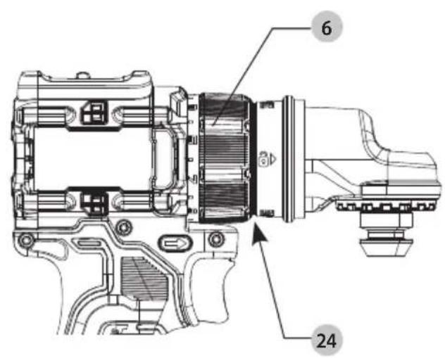
text_image
Technical diagram of a camera module with labeled parts and numbered annotationsFig. E2Fig. E1
natural_image
Technical line drawing of a mechanical device with internal components and a right-angle view (no text or symbols)Fig. F Fig. G
text_image
22 21 18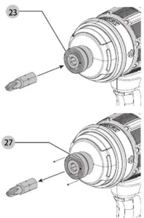
text_image
23 27Fig. H
text_image
6 DEWALTFig.1
text_image
g.1 DEWAT 3 1Fig. J Fig. K
text_image
26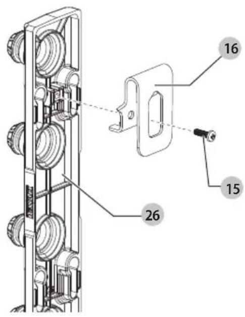
text_image
Technical diagram of a mechanical assembly with numbered parts and labeled componentsFig. L
text_image
17 28Fig. M
text_image
Technical diagram of a mechanical assembly with labeled components and numbered parts18 V B∅RSTEL∅S MULTIHOVED BOREMASKINE/SKRUEMASKINE
DCD803

text_image
Three black-and-white icons: a trash bin with a crossed-out mechanism, a person recycling arrows, and a QR code.Vice President of Engineering Europe
WARNING: Read all safety warnings, instructions, illustrations, and specifications in this manual, including the battery and charger sections provided in an original tool manual or the separate Batteries and Chargers manual. Manuals can be obtained by contacting

Customer Service (refer to the back page of this manual).
Technical Data
| DCD803 | ||
| Voltage V | _DC | 18 |
| Type 10 | ||
| Battery type Li-Ion | ||
| No load speed | ||
| 1st gear min | -1 | 0–450 |
| 2nd gear 0–1650 | ||
| Max. torque Nm 73 | ||
| Chuck capacity mm 1.5–13 | ||
| Weight (without battery pack/attachment) | kg | 0.97 |
| Weight (without battery pack/with attachment) | kg | 1.34 |
| Noise values and vibration values (triax vector sum) according to EN62841-2-1 and EN62841-2-2: | ||
| L_PA (emission sound pressure level) | dB(A) | 77 |
| L_WA (sound power level) | dB(A) | 85 |
| K (uncertainty for the given sound level) | dB(A) | 5 |
| Drilling into metal | ||
| Vibration emission value a_h,D = | m/s ^2 | <2.5 |
| Uncertainty K = | m/s | 1.5 |
| Screwdriving | ||
| Vibration emission value a_h = | m/s ^2 | <2.5 |
| Uncertainty K = | m/s | 1.5 |
The vibration and/or noise emission level given in this information sheet has been measured in accordance with a standardised test given in EN62841 and may be used to compare one tool with another. It may be used for a preliminary assessment of exposure.
WARNING: The declared vibration and/or noise emission level represents the main applications of the tool. However, if the tool is used for different applications, with different accessories or is poorly maintained, the vibration and/or noise emission may differ. This may significantly increase the exposure level over the total working period. An estimation of the level of exposure to vibration and/or noise should also take into account the times when the tool is switched off or when it is running but not actually doing the job. This may significantly reduce the exposure level over the total working period.
Identify additional safety measures to protect the operator from the effects of vibration and/or noise such as: maintain the tool and the accessories, keep the hands warm (relevant for vibration), organisation of work patterns.
EC-Declaration of Conformity Machinery Directive

MULTI-HEAD Drill/Driver DCD803 Type 10
We, the manufacturer as stated below, declares that these products described under Technical Data are in compliance with: 2006/42/EC, EN62841-1:2015+A11:2022, EN 62841-2-1:2018 + A11:2019 + A12:2022 + A1:2022, EN 62841-2-2:2014 + AC:2015. These products also comply with Directive 2014/30/EU and 2011/65/EU. For more information, please contact us at the following address or refer to the back of the manual. The undersigned is responsible for compilation of the technical file and makes this declaration on behalf of the manufacturer.

text_image
Mr. RergelMarkus Rompel
Vice President of Engineering Europe Stanley Black and Decker Deutschland GmbH DEWALT, Richard-Klinger-Strasse 11, 65510, Idstein, Germany 31.07.2025

WARNING: To reduce the risk of injury, read the auction manual.
Definitions: Safety Guidelines
The definitions below describe the level of severity for each signal word. Please read the manual and pay attention to these symbols.
RANGER: Indicates an imminently hazardous situation which, if not avoided, will result in death or serious injury.
WARNING: Indicates a potentially hazardous situation which, if not avoided, could result in death or serious injury.
▲AUTION: Indicates a potentially hazardous situation which, if not avoided, may result in minor or moderate injury. NOTICE: Indicates a practice not related to personal injury which, if not avoided, may result in property damage.
▲penotes risk of electric shock.
A denotes risk of fire.
GENERAL POWER TOOL SAFETY WARNINGS
WARNING: Read all safety warnings, instructions, illustrations and specifications provided with this power tool. Failure to follow all instructions listed below may result in electric shock, fire and/or serious injury.
SAVE ALL WARNINGS AND INSTRUCTIONS FOR FUTURE REFERENCE
The term "power tool" in the warnings refers to your mains-operated (corded) power tool or battery-operated (cordless) power tool.
1) Work Area Safety
a) Keep work area clean and well lit. Cluttered or dark areas invite accidents.
b) Do not operate power tools in explosive atmospheres, such as in the presence of flammable liquids, gases or dust. Power tools create sparks which may ignite the dust or fumes.
c) Keep children and bystanders away while operating a power tool. Distractions can cause you to lose control.
2) Electrical Safety
a) Power tool plugs must match the outlet. Never modify the plug in any way. Do not use any adapter plugs with earthed (grounded) power tools. Unmodified plugs and matching outlets will reduce risk of electric shock.
b) Avoid body contact with earthed or grounded surfaces, such as pipes, radiators, ranges and refrigerators. There is an increased risk of electric shock if your body is earthed or grounded.
c) Do not expose power tools to rain or wet conditions. Water entering a power tool will increase the risk of electric shock.
d) Do not abuse the cord. Never use the cord for carrying, pulling or unplugging the power tool. Keep cord away from heat, oil, sharp edges or moving parts. Damaged or entangled cords increase the risk of electric shock.
e) When operating a power tool outdoors, use an extension cord suitable for outdoor use. Use of a cord suitable for outdoor use reduces the risk of electric shock.
f) If operating a power tool in a damp location is unavoidable, use a residual current device (RCD) protected supply. Use of an RCD reduces the risk of electric shock.
3) Personal Safety
a) Stay alert, watch what you are doing and use common sense when operating a power tool. Do not use a power tool while you are tired or under the influence of drugs, alcohol or medication. A moment of inattention while operating power tools may result in serious personal injury.
b) Use personal protective equipment. Always wear eye protection. Protective equipment such as a dust mask, non-skid safety shoes, hard hat or hearing protection used for appropriate conditions will reduce personal injuries.
c) Prevent unintentional starting. Ensure the switch is in the off-position before connecting to power source and/or battery pack, picking up or carrying the tool. Carrying power tools with your finger on the switch or energising power tools that have the switch on invites accidents.
d) Remove any adjusting key or wrench before turning the power tool on. A wrench or a key left attached to a rotating part of the power tool may result in personal injury.
e) Do not overreach. Keep proper footing and balance at all times. This enables better control of the power tool in unexpected situations.
f) Dress properly. Do not wear loose clothing or jewellery. Keep your hair and clothing away from moving parts. Loose clothes, jewellery or long hair can be caught in moving parts.
g) If devices are provided for the connection of dust extraction and collection facilities, ensure these are connected and properly used. Use of dust collection can reduce dust-related hazards.
h) Do not let familiarity gained from frequent use of tools allow you to become complacent and ignore tool safety principles. A careless action can cause severe injury within a fraction of a second.
4) Power Tool Use and Care
a) Do not force the power tool. Use the correct power tool for your application. The correct power tool will do the job better and safer at the rate for which it was designed.
b) Do not use the power tool if the switch does not turn it on and off. Any power tool that cannot be controlled with the switch is dangerous and must be repaired.
c) Disconnect the plug from the power source and/or remove the battery pack, if detachable, from the power tool before making any adjustments, changing accessories, or storing power tools. Such preventive safety measures reduce the risk of starting the power tool accidentally.
d) Store idle power tools out of the reach of children and do not allow persons unfamiliar with the power tool or these instructions to operate the power tool. Power tools are dangerous in the hands of untrained users.
e) Maintain power tools and accessories. Check for misalignment or binding of moving parts, breakage of parts and any other condition that may affect the power tool's operation. If damaged, have the power tool repaired before use. Many accidents are caused by poorly maintained power tools.
f) Keep cutting tools sharp and clean. Properly maintained cutting tools with sharp cutting edges are less likely to bind and are easier to control.
g) Use the power tool, accessories and tool bits, etc. in accordance with these instructions, taking into account the working conditions and the work to be performed. Use of the power tool for operations different from those intended could result in a hazardous situation.
h) Keep handles and grasping surfaces dry, clean and free from oil and grease. Slippery handles and grasping surfaces do not allow for safe handling and control of the tool in unexpected situations.
5) Battery Tool Use and Care
a) Recharge only with the charger specified by the manufacturer. A charger that is suitable for one type of battery pack may create a risk of fire when used with another battery pack.
b) Use power tools only with specifically designated battery packs. Use of any other battery packs may create a risk of injury and fire.
c) When battery pack is not in use, keep it away from other metal objects, like paper clips, coins, keys, nails, screws or other small metal objects, that can make a connection from one terminal to another. Shorting the battery terminals together may cause burns or a fire.
d) Under abusive conditions, liquid may be ejected from the battery; avoid contact. If contact accidentally occurs, flush with water. If liquid contacts eyes, additionally seek medical help. Liquid ejected from the battery may cause irritation or burns.
e) Do not use a battery pack or tool that is damaged or modified. Damaged or modified batteries may exhibit unpredictable behaviour resulting in fire, explosion or risk of injury.
f) Do not expose a battery pack or tool to fire or excessive temperature. Exposure to fire or temperature above 130 °C may cause explosion.
g) Follow all charging instructions and do not charge the battery pack or tool outside the temperature range specified in the instructions. Charging improperly or at temperatures outside the specified range may damage the battery and increase the risk of fire.
6) Service
a) Have your power tool serviced by a qualified repair person using only identical replacement parts. This will ensure that the safety of the power tool is maintained.
b) Never service damaged battery packs. Service of battery packs should only be performed by the manufacturer or authorised service providers.
Safety Instructions for All Operations
- Hold the power tool by insulated gripping surfaces, when performing an operation where the cutting accessory or the fastener may contact hidden wiring. Cutting accessory or the fastener contacting a "live" wire may make exposed metal parts of the power tool "live" and could give the operator an electric shock.
Safety Instructions When Using Long Drill Bits
- Never operate at higher speed than the maximum speed rating of the drill bit. At higher speeds, the bit is likely to bend if allowed to rotate freely without contacting the workpiece, resulting in personal injury.
• Always start drilling at low speed and with the bit tip in contact with the workpiece. At higher speeds, the bit is likely to bend if allowed to rotate freely without contacting the workpiece, resulting in personal injury. - Apply pressure only in direct line with the bit and do not apply excessive pressure. Bits can bend causing breakage or loss of control, resulting in personal injury.
Additional Safety Warnings for Drills
- Use clamps or other practical way to secure and support the workpiece to a stable platform. Holding the work by hand or against your body is unstable and may lead to loss of control.
- Accessories and tool may get hot during operation. Wear gloves when handling them if performing heat producing applications such as drilling metals.
• Air vents often cover moving parts and should be avoided. Loose clothes, jewelry or long hair can be caught in moving parts.
Residual Risks
In spite of the application of the relevant safety regulations and the implementation of safety devices, certain residual risks cannot be avoided. These are:
- Impairment of hearing.
- Risk of personal injury due to flying particles.
- Risk of burns due to accessories becoming hot during operation.
- Risk of personal injury due to prolonged use.
Compatible Batteries and Chargers
These battery packs may be used:
| Battery(kg) | Battery(kg) | ||
| DCB5461.08 | DCB1850.35 | ||
| DCB547/G1.46 | DCB1870.54 | ||
| DCB5481.46 | DCB1880.95 | ||
| DCB5492.12 | DCB1890.54 | ||
| DCB1810.35 | DCBP034/G0.32 | ||
| DCB1820.61 | DCBP518/G0.75 | ||
| DCB183/B/G | 0.40 | DCB1880 | 0.98 |
| DCB184/B/G | 0.62 | DCBP318 | 0.50 |
These chargers may be used: DCB104, DCB107, DCB112/DCB1102, DCB115/DCB1104, DCB117/DCB1112, DCB118, DCB132.
Refer to the battery/charger manual for more information.
Package Contents
The package contains:
1Drill/driver
4Attachmentheads
1Charger
1 Li-Ion battery pack (C1, D1, L1, M1, P1, S1, T1, X1, Y1 models)
2 Li-lon battery packs (C2, D2, L2, M2, P2, S2, T2, X2, Y2 models)
3 Li-Ion battery packs (C3, D3, L3, M3, P3, S3, T3, X3, Y3 models)
1 Instructionmanual
NOTE: Battery packs, chargers and kitboxes are not included with N models. Battery packs and chargers are not included with NT models. B models include Bluetooth® battery packs.
NOTE: The Bluetooth® word mark and logos are registered trademarks owned by the Bluetooth®, SIG, Inc. and any use of such marks by DEWALT is under license. Other trademarks and trade names are those of their respective owners.
- Check for damage to the tool, parts or accessories which may have occurred during transport.
• Take the time to thoroughly read and understand this manual prior to operation.
Markings on Tool
The following pictograms are shown on the tool:

Read instruction manual before use.

Visible radiation. Do not stare into light.
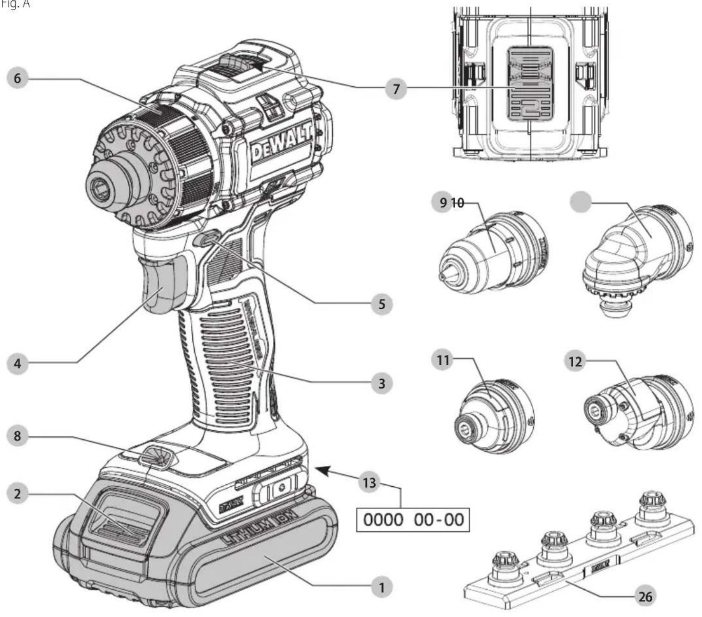
Date Code Position (Fig. A)
The production date code 13 consists of a 4-digit year followed by a 2-digit week and is extended by a 2-digit factory code.
Description (Fig. A)
WARNING: Never modify the power tool or any part of it.
Damage or personal injury could result.
Components
1 Battery pack
2 Battery pack release button
3 Main handle
4 Variable speed trigger switch
5 Forward/reverse control/lock-off button
6 Mode selection collar
7 Speed selector
8 Worklight
9 Metal chuck attachment
10 Right angle attachment
11 Quick release attachment
12 Quick release offset attachment
13 Date code position
Intended Use
This drill/driver is designed for professional drilling and screwdriving applications.
DO NOT use under wet conditions or in the presence of flammable liquids or gases.
This drill/driver is a professional power tool.
DO NOT let children come into contact with the tool. Supervision is required when inexperienced operators use this tool.
- Young children and the infirm. This appliance is not intended for use by young children or infirm persons without supervision.
- This product is not intended for use by persons (including children) suffering from diminished physical, sensory or mental abilities; lack of experience, knowledge or skills unless they are supervised by a person responsible for their safety. Children should never be left alone with this product.
ASSEMBLY AND ADJUSTMENTS
WARNING: To reduce the risk of serious personal injury, turn tool off and disconnect battery pack before making any adjustments or removing/installing attachments or accessories. An accidental start-up can cause injury.
WARNING: Use only DEWALT batteries and chargers.
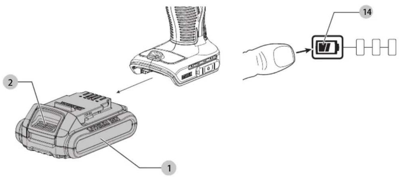
Inserting and Removing the Battery Pack from the Tool (Fig. B)
NOTE: Make sure your battery pack 1 is fully charged.
To Install the Battery Pack into the Tool Handle
- Align the battery pack with the rails inside the tool's handle (Fig. B).
- Slide it into the handle until the battery pack is firmly seated in the tool and ensure that you hear the lock snap into place.
To Remove the Battery Pack from the Tool
- Press the battery release button 2 and firmly pull the battery pack out of the tool handle.
- Insert battery pack into the charger.
Fuel Gauge Battery Packs (Fig. B)
Some DEWALT battery packs include a fuel gauge 14, which consists of three green LED lights that indicate the level of charge remaining in the battery pack.
To actuate the fuel gauge, press and hold the fuel gauge button. A combination of the three green LED lights will illuminate, designating the level of charge left. When the level of charge in the battery is below the usable limit, the fuel gauge will not illuminate and the battery will need to be recharged.
NOTE: The fuel gauge is only an indication of the charge left on the battery pack. It does not indicate tool functionality and is subject to variation based on product components, temperature and end-user application.
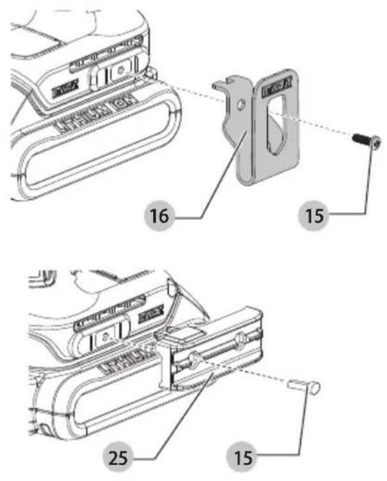
Belt Hook and Magnetic Bit Holder (Fig. C) (Optional Accessories)
WARNING: To reduce the risk of serious personal injury, ONLY use the tool's belt hook to hang the tool from a work belt. DO NOT use the belt hook for tethering or securing the tool to a person or object during use. DO NOT suspend tool overhead or suspend objects from the belt hook.
WARNING: To reduce the risk of serious personal injury, ensure the screw holding the belt hook is secure.
IMPORTANT: When attaching or replacing the belt hook 16 or magnetic bit holder 25, use only the mounting screw 15 that is provided. Be sure to securely tighten the screw.
The belt hook and magnetic bit holder can be attached to either side of the tool using only the screw provided, to accommodate left- or right-handed users. If the belt hook or magnetic bit holder is not desired at all, it can be removed from the tool.
To move the belt hook or magnetic bit clip, remove the screw that holds it in place then reassemble on the opposite side. Be sure to securely tighten the screw.
The belt hook can also be used to hang the attachment organizer. Refer to Attachment Organizer.
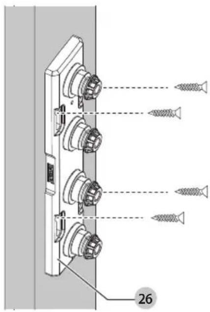
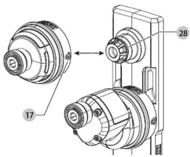
Attachment Organizer (Fig. J–L)
This tool comes with an attachment organizer 26 that holds up to 4 attachment heads. The attachment organizer has 4 keyhole slots allowing the organizer to be wall mounted by screws or nails for storage purposes (Fig. J).
To mount an attachment, push the attachment head directly over the attachment holder 28 until the collar of the attachment touches the back of the organizer (Fig. L).
To remove an attachment, pull on the collar 17 of the attachment and remove away from the organizer.
Belt Hook Option
The belt hook 16 can also be attached to the back of the attachment organizer allowing the organizer to be hung (Fig. K).
IMPORTANT: When attaching or replacing the belt hook, use only the screw 15 that is provided. Be sure to securely tighten the screw.
NOTE: If mounting directly to wall be sure to remove belt hook on the back.
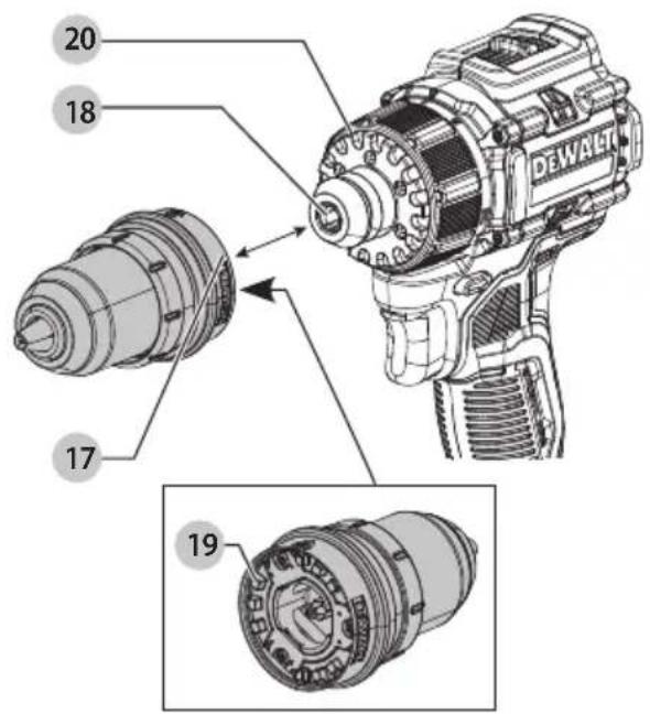
Installing and Removing Attachments (Fig. A, D–E2)
WARNING: Shock hazard. Under no circumstances should this product be used near water.
WARNING: Burn hazard. Moving parts within the power unit become hot during use. Avoid contact with moving parts within power unit when removing and installing accessories.
WARNING: Before assembly, lock the power unit by setting the forward/reverse slider to the center position and remove the battery from the tool. Remove any accessory from the attachment before removing or installing the attachment.
Located on the front of tool's mode selection collar 6, the tool comes equipped with a yellow ring 24 feature to indicate if the attachment is properly connected and locked into position on the tool (Fig. E1).
-
Slide the attachment onto the spindle 18, aligning the lugs 19 on the attachment with the slots 20 around the spindle (Fig. D).
-
Once on the spindle, rotate the head of the attachment slightly until the lugs snap into the slots. If the attachment is connected securely and locked into position the yellow ring around the collar of the attachment should no longer be visible (Fig. E2).
NOTE: Ensure that the yellow ring 24 is no longer visible before use.
- To remove the attachment, pull on the collar 17 of the attachment and remove away from the tool (Fig. D).
NOTE: There is no need to rotate the attachment when removing from the tool.
NOTE: The 6.35 mm hex right angle attachment 10 allows additional attachments to be installed on its spindle. With the 6.35 mm hex right angle attachment installed on the tool follow instruction 1, 2, and 3 to install and remove additional attachments.
NOTE: Only use attachments that are specifically designed for and compatible with the power unit. Refer to individual attachment instruction manuals for specific safety warnings and operating instructions before operating attachments with the power unit.
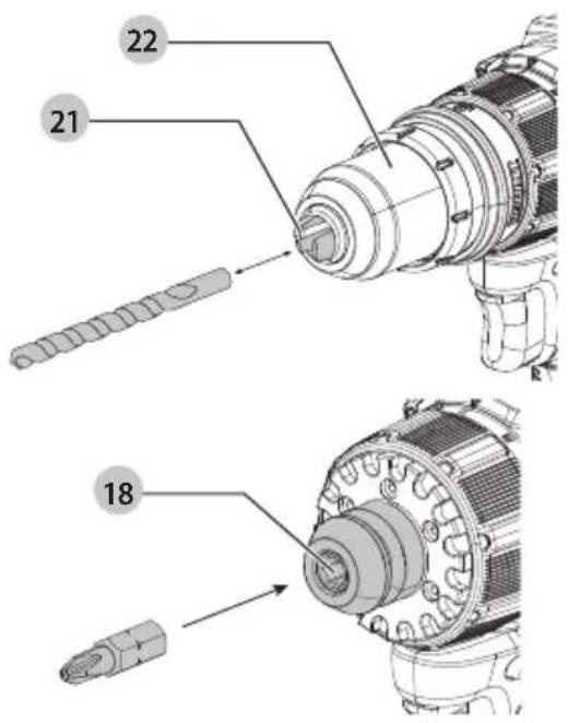
Installing a Bit or Accessory into a Keyless Chuck (Fig. A, F)
WARNING: Do not attempt to tighten drill bits (or any other accessory) by gripping the front part of the chuck and turning the tool on. Damage to the chuck and personal injury may result. Always lock off trigger switch and disconnect tool from power source when changing acces sories.
WARNING: Always ensure the bit is secure before starting the tool. A loose bit may eject from tool causing possible personal injury.
Your tool features a keyless chuck 21 with one rotating chuck sleeve 22 for one-handed operation of the chuck. To insert a drill bit or other accessory, follow these steps.
- Turn tool off and remove battery pack 1.
- Grasp the black sleeve of the chuck with one hand and use the other hand to secure the tool. Rotate the sleeve counterclockwise far enough to accept the desired accessory.
- Insert the accessory about 19 mm into the keyless chuck 21 and tighten securely by rotating the chuck sleeve 22 clockwise with one hand while holding the tool with the other. When the chuck is nearly tightened you will hear a clicking sound. Your tool is equipped with an automatic spindle lock mechanism. This allows you to open and close the chuck with one hand.
- Be sure to tighten chuck with one hand on the chuck sleeve and one hand holding the tool for maximum tightness.
- To release the accessory, repeat steps 1 and 2 above.
Quick-Release Chuck (Fig. A, G)
The 1/4" hex quick release attachment 11, and 1/4" hex quick release offset attachment 12 use a quick release chuck.
NOTE: The chuck accepts 1/4" (6.35 mm) hex accessories and 1" (25.4 mm) bit tips only.
Place the forward/reverse/lock-off button 5 in the lock-off (center) position and remove battery pack before changing accessories.
To install an accessory, fully insert the accessory into the quick-release chuck 23. The accessory is locked into place.
To remove an accessory, pull the chuck collar 27 away from the front of the tool. Remove the accessory from the quick-release chuck 23.
Installing a Bit or Accessory with No Attachment (Fig. F)
You can use your tool without installing an attachment. Insert a hex bit directly into the spindle 18. It is held in place magnetically.
OPERATION
Instructions for Use
WARNING: Always observe the safety instructions and applicable regulations.
WARNING: To reduce the risk of serious personal injury, turn tool off and disconnect battery pack before making any adjustments or removing/installing attachments or accessories.
An accidental start-up can cause injury.
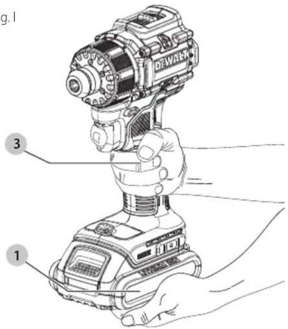
Proper Hand Position (Fig. I)
WARNING: To reduce the risk of serious personal injury, ALWAYS use proper hand position as shown.
WARNING: To reduce the risk of serious personal injury, ALWAYS hold securely in anticipation of a sudden reaction. Proper hand position requires one hand on the main handle 3 and the other hand holding the battery pack 1.
Speed Selection (Fig. A)
The tool features two speed settings for greater versatility.
NOTE: Do not change speeds when the tool is running Always allow the tool to come to a complete stop before changing speed.
- To select speed 1 (high torque setting), turn the tool off and permit it to stop. Slide the speed selector 7 back (away from the chuck).
- To select speed 2 (high speed setting), turn the tool off and permit it to stop. Slide the speed selector forward (toward the chuck).
- If the tool does not change speeds, confirm that the speed selection switch is completely engaged in the forward or back position.
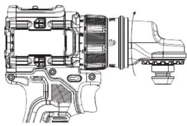
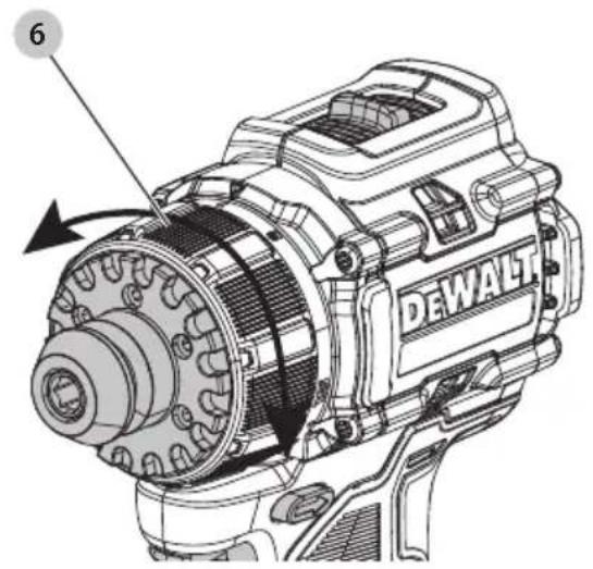
Mode Selection (Fig. H)
The mode selection collar 6 can be used to select the correct operating mode depending upon the planned application. To select, rotate the collar until the desired symbol aligns with the arrow.
WARNING: When the mode selection collar is in the drill position, the drill will not clutch. The drill may stall if overloaded, causing a sudden twist.
| Symbol Mode | |
| Drilling | |
| 1-15 Screw driving (higher number = greater torque) | |
Variable Speed Trigger and Forward/Reverse Control Button (Fig. A)
The tool is turned on and off by pulling and releasing the variable speed trigger switch 4. The farther the trigger is depressed, the higher the speed of the tool. Your tool is equipped with a brake. The chuck will stop as soon as the trigger switch is fully released.
A forward/reverse control button 5 determines the rotational direction of the tool and also serves as a lock-off button.
- To select forward rotation (clockwise), release the trigger and depress the forward/reverse control button on the right side of the tool.
- To select reverse (counterclockwise), depress the forward/ reverse control button on the left side of the tool.
NOTE: The centre position of the control button locks the tool in the off position. When changing the position of the control button, be sure the trigger is released.
NOTE: Continuous use in variable speed range is not recommended. It may damage the switch and should be avoided.
NOTE: The first time the tool is run after changing the direction of rotation, you may hear a click on start-up. This is normal and does not indicate a problem.
Worklight (Fig. A)
The worklight 8 is activated when the variable speed trigger switch 4 is depressed, and will automatically turn off 20 seconds after the variable speed trigger switch is released. If the variable speed trigger switch remains depressed, the worklight will remain on.
NOTE: The worklight is for lighting the immediate work surface and is not intended to be used as a flashlight.
Performing an Application (Fig. A)
WARNING: To reduce the risk of personal injury, ALWAYS
ensure workpiece is anchored or clamped firmly.
WARNING: Always wait until the motor has come to a
complete standstill before changing the direction of rotation.
Prior to Performing Work
- Set the speed selector 7. Refer to Speed Selection.
• Install the appropriate bit or accessory into the chuck. Refer to accessory installation instructions in this manual.
WARNING:
- Do not use this tool to mix or pump easily combustible or explosive fluids (benzine, alcohol, etc.).
- Do not mix or stir flammable liquids labeled accordingly.
Screwdriving
Your tool has a clutch with adjustable torque for driving and removing a wide array of fastener shapes and sizes. The numbers 1–15 on the mode selection collar 6 are used to set a torque range for screwdriving. The higher the number on the collar, the higher the torque and the larger the fastener which can be driven.
- Turn the mode selection collar 6 to the desired position.
Mode Selection.
- Pull the variable speed trigger switch 4 applying pressure in a straight line with the bit until the fastener is seated at the desired depth in the workpiece.
Recommendations for Screwdriving
- Start with lower torque settings, then advance to higher torque settings to avoid damage to the workpiece or fastener.
- Make some practice runs in scrap or on unseen areas of the workpiece to determine the proper position of the mode selection collar.
Drilling
- Turn the mode selection collar 6 to the "drill symbol." Refer to Mode Selection.
- Place drill bit in contact with the workpiece.
NOTE: Use sharp drill bit only.
- Pull the variable speed trigger switch 4 applying pressure in a straight line with the bit until it reaches the desired depth.
WARNING: Drill may stall if overloaded causing a sudden twist. Always expect the stall. Grip the drill firmly to control the twisting action and avoid injury.
4. Keep the motor running when pulling the bit back out of a drilled hole to prevent jamming.
Recommendations for Drilling
- When drilling, always apply pressure in a straight line with the bit, but do not push hard enough to stall the motor or deflect the bit.
• IF THE DRILL STALLS:
- RELEASE TRIGGER SWITCH IMMEDIATELY, remove drill bit from work, and determine cause of stalling.
- DO NOT DEPRESS TRIGGER SWITCH ON AND OFF IN AN ATTEMPT TO START A STALLED DRILL—THIS CAN DAMAGE THE DRILL.
- To minimize stalling or breaking through the material, reduce pressure on drill and ease the bit through the last fractional part of the hole.
- Large holes, 8 ~mm to 13 ~mm in steel, can be made easier if a pilot hole, 4 ~mm to 5 ~mm , is drilled first.
- If drilling thin material or material that is prone to splinter, use a wood "back-up" block to prevent damage to the workpiece.
MAXIMUM RECOMMENDED CAPACITIES
| DCD803 | ||
| Chuck Attachment | Right Angle AttachmentQuick Release AttachmentQuick Release Offset AttachmentHex Spindle(Recommended with 6.35 mm Hex Bits) | |
| WOODAuger 31.75 mm (1-1/4") Screwdriving OnlyPaddle 38 mm (1-1/2") Screwdriving OnlyTwist 12.7 mm (1/2") Screwdriving OnlySelf-feed 54 mm (2-1/8") Screwdriving OnlyHole saw 57 mm (2-1/4") Screwdriving Only | ||
| METALTwist 9.5 mm (3/8") Screwdriving Only | ||
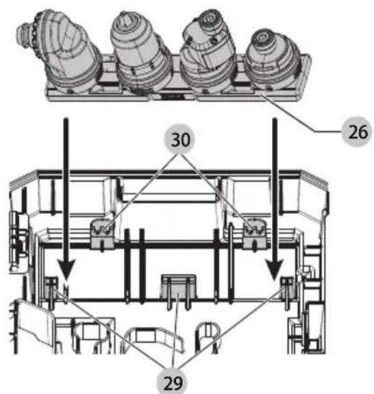
Mounting/Releasing Attachment Organizer from Kit Box (Fig. M)
To mount attachment organizer into kit box:
- Place one side of the attachment organizer 26 under all fixed ribs 29 and ensure the flexible ribs 30 are outside of the opposite side of the attachment organizer.
- Push the other side of the attachment organizer down allowing the flexible ribs to snap around the edge of the attachment organizer locking it in place.
To release attachment organizer from kit box:
- Bend the flexible ribs 30 away from edge of the attachment organizer 26 while pulling the attachment organizer out and away from the fixed ribs.
MAINTENANCE
Your power tool has been designed to operate over a long period of time with a minimum of maintenance. Continuous satisfactory operation depends upon proper tool care and regular cleaning.
WARNING: To reduce the risk of serious personal injury, turn tool off and disconnect battery pack before making any adjustments or removing/installing attachments or accessories. An accidental start-up can cause injury.
The charger and battery pack are not serviceable.
Please refer to the back page of this manual for service centre contact information, or visit www.2helpU.com.
Lubrication
Your power tool requires no additional lubrication.
Cleaning
WARNING: Electrical shock and mechanical hazard.
Disconnect the plug from the power source and/or remove the battery pack, if detachable, from the product before cleaning.
WARNING: To ensure safe and efficient operation, always keep the product and the ventilation slots (if applicable) clean. Ventilation slots can be cleaned using a dry, soft non-metallic
brush and/or a suitable vacuum cleaner. Do not use water or any cleaning solutions.
WARNING: Blow dirt and dust out of the main housing with dry air as often as dirt is seen collecting in and around the ventilation slots. Wear approved eye protection and approved dust mask when performing this procedure.
WARNING: Never use solvents or other harsh chemicals for cleaning the non-metallic parts of the product. These chemicals may weaken the materials used in these parts. Use a cloth dampened only with water and mild soap. Never let any liquid get inside the product. Never immerse any part of the product into a liquid.
Reducing Dust Exposure
Before starting work, check the hazard class of the dust that will be produced when working.
WARNING: Avoid touching or breathing dust as it can be harmful to health. Dust created when using a power tool and when conducting other construction activities can contain chemicals, minerals, or particles known to cause respiratory infections, allergic reactions, cancer, birth defects, or other reproductive harm of the user or bystanders.
- Such dust can be generated, for example, when working on hardwoods such as beech or oak, lead-based paint, concrete, masonry, or stones containing quartz.
- Material containing asbestos may be handled only by specialists.
- Observe the relevant regulations in your country for the materials to be worked on.
- Use a dust extractor or extraction system with an officially approved protection class in compliance with the locally applicable dust protection regulations and suitable for the material to be worked on.
- Capture the resulting dust particles directly at the source and avoid deposits in the surrounding area. Use suitable extraction accessories for this purpose.
Additional measures:
- Make sure that the workplace is well ventilated.
- Wear a respirator appropriate for the type of dust generated.
Optional Accessories
WARNING: Since accessories, other than those offered by DEWALT, have not been tested with this product, use of such accessories with this tool could be hazardous. To reduce the risk of injury, only DEWALT recommended accessories should be used with this product.
Consult your dealer for further information on the appropriate accessories.
Protecting the Environment


Products/batteries are recyclable, but if marked with the crossed-out bin, they must not be disposed of with normal household waste.
Run the batteries down completely and separate them, and separate any light sources from the product if possible. It is the user's responsibility to delete personal data from the product. Then take the waste to an official waste collection centre or a participating retailer who will often accept it free of charge. Packaging should be discarded based on the marked
material code. Operating and safety instructions should only be discarded once the applicable product is no longer in use. Please check with your local community/municipality for waste management guidance. For further information, visit www.2helpU.com and scan the above QR code.
TALADRO ATORNILLADOR MULTICABEZAL SIN ESCOBILLAS
DE 18 V
DCD803

text_image
Mr. Georg Molecular LaboratoryMarkus Rompel
Vice President of Engineering Europe
text_image
Mr. Georg Molecular LaboratoryMarkus Rompel
Vicepresidente Engineering Europe
WAARSCHUWING: Lees alle
WAARSCHUWING: Lees alle
BEWAAR ALLE WAARSCHUWINGEN EN INSTRUCTIES ALS TOEKOMSTIG REFERENTIEMATERIAAL
3 Li-Ion-accu's (modellen C3, D3, L3, M3, P3, S3, T3, X3, Y3)
Anbefalinger for boring
text_image
Three QR codes: a trash bin with cross symbol, a person recycling with arrows, and a QR code.text_image
Three black-and-white icons: a trash bin with cross symbol, a person recycling symbol with arrows, and a QR code.text_image
Mr. Georg Mudan, RangalMarkus Rompel