
HPA6 - Processor ALTO - Free user manual and instructions
Find the device manual for free HPA6 ALTO in PDF.
| Product Type | 6-Channel Stereo Headphone Amplifier |
| Brand | Alto Professional |
| Model | HPA6 |
| Dimensions (W x D x H) | 483 mm (19 inches) x 200 mm x 44 mm (1U) |
| Weight | 2.8 kg (approx.) |
| Power Supply | 100-240 V AC, 50-60 Hz |
| Power Consumption | 30 W (max) |
| Number of Channels | 6 independent stereo channels |
| Main Inputs | 6 x XLR / TRS 1/4" (6.35 mm) balanced |
| Auxiliary Inputs | 6 x TRS 1/4" stereo |
| Front Direct Input | 1 x TRS 1/4" |
| Headphone Outputs | 6 x TRS 1/4" front + 12 x TRS 1/4" rear (18 outputs total) |
| Main Outputs | 6 x XLR / TRS 1/4" balanced (for daisy chaining) |
| Minimum Load Impedance per Channel | 100 Ω (1 headphone), 200 Ω (2 headphones), 300 Ω (3 headphones) |
| Frequency Response | 20 Hz - 20 kHz (±0.5 dB) |
| Signal-to-Noise Ratio | > 100 dB |
| Key Features | 6 independent headphone amps, mono/stereo mix, left/right mute, main/aux input balance, LED VU meters, clipping detection |
| Safety | Protective fuse, grounding via power cord, compliance with OSHA sound exposure limits |
| Maintenance and Cleaning | Unplug before cleaning; use a soft dry cloth; do not use solvents |
| Spare Parts and Repairability | Spare fuse (identical type); for other repairs, contact an authorized service center |
| Included Accessories | Power cord, user guide, safety instructions booklet |
| Warranty | Standard manufacturer's warranty (refer to booklet) |
| General Information | 19" 1U rack unit; gold-plated connectors; short signal path circuit; robust QS9000 certified construction |
Frequently Asked Questions - HPA6 ALTO
User questions about HPA6 ALTO
0 question about this device. Answer the ones you know or ask your own.
Ask a new question about this device
Download the instructions for your Processor in PDF format for free! Find your manual HPA6 - ALTO and take your electronic device back in hand. On this page are published all the documents necessary for the use of your device. HPA6 by ALTO.
USER MANUAL HPA6 ALTO
HPA6
USER GUIDE
ENGLISH (2-7)
GUÍA DEL USUARIO
ESPAÑOL (8 - 14)
GUIDE D'UTILISATION
FRANÇAIS (15 - 20)
GUIDA PER L'USO
ITALIANO (21 - 26)
BENUTZERHANDBUCH
DEUTSCH (27 - 32)
GEBRUIKERSHANDLEIDING
NEDERLANDS (33 - 38)
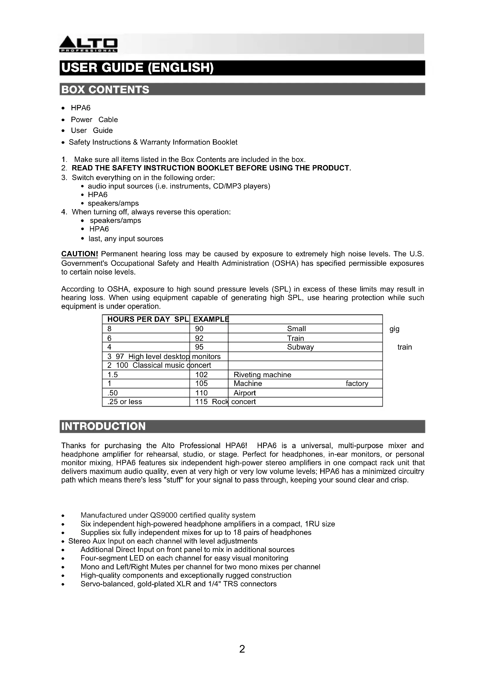
USER GUIDE (ENGLISH)
BOX CONTENTS
- HPA6
- Power Cable
- User Guide
-
Safety Instructions & Warranty Information Booklet
-
Make sure all items listed in the Box Contents are included in the box.
- READ THE SAFETY INSTRUCTION BOOKLET BEFORE USING THE PRODUCT.
- Switch everything on in the following order:
• audio input sources (i.e. instruments, CD/MP3 players)
- HPA6
- speakers/amps
-
When turning off, always reverse this operation:
-
speakers/amps
- HPA6
- last, any input sources
CAUTION! Permanent hearing loss may be caused by exposure to extremely high noise levels. The U.S. Government's Occupational Safety and Health Administration (OSHA) has specified permissible exposures to certain noise levels.
According to OSHA, exposure to high sound pressure levels (SPL) in excess of these limits may result in hearing loss. When using equipment capable of generating high SPL, use hearing protection while such equipment is under operation.
| HOURS PER DAY SPL | EXAMPLE | |
| 8 | 90 | Small |
| 6 | 92 | Train |
| 4 | 95 | Subway |
| 3 97 High level desktop monitors | ||
| 2 100 Classical music concert | ||
| 1.5 | 102 | Riveting machine |
| 1 | 105 | Machine factory |
| .50 | 110 | Airport |
| .25 or less | 115 Rock concert | |
gig train
INTRODUCTION
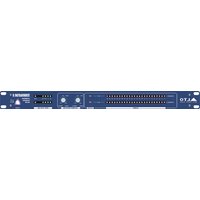
Thanks for purchasing the Alto Professional HPA6! HPA6 is a universal, multi-purpose mixer and headphone amplifier for rehearsal, studio, or stage. Perfect for headphones, in-ear monitors, or personal monitor mixing, HPA6 features six independent high-power stereo amplifiers in one compact rack unit that delivers maximum audio quality, even at very high or very low volume levels; HPA6 has a minimized circuitry path which means there's less "stuff" for your signal to pass through, keeping your sound clear and crisp.
• Manufactured under QS9000 certified quality system
• Six independent high-powered headphone amplifiers in a compact, 1RU size
• Supplies six fully independent mixes for up to 18 pairs of headphones
- Stereo Aux Input on each channel with level adjustments
• Additional Direct Input on front panel to mix in additional sources
• Four-segment LED on each channel for easy visual monitoring
• Mono and Left/Right Mutes per channel for two mono mixes per channel
• High-quality components and exceptionally rugged construction
• Servo-balanced, gold-plated XLR and 1/4" TRS connectors
FRONT PANEL CONTROLS

- Direct input - Feeds an external audio source directly into the main signal path.
- Input gain control - Controls the signal level going to the Main or Direct Inputs.
- Input level meter - Displays the signal level coming from Main/Direct Inputs. For the best quality of input signal, the LED should range from +6 to +18 dBu. If the Clip LED (in the Output Level Meter) is always on, reduce the input level using the input gain control.
- Aux input - Provides a separate stereo input signal which can be mixed with the Main/Direct Input signal.
- L mute switch - Mutes the left input signal.
- R mute switch - Mutes the right input signal.
- Mode switch - Switches the operational mode between mono and stereo.
- Mono LED - This LED lights up when the unit is in mono mode. When the LED is off, the unit is in stereo mode.
- Headphone output - 1/4" TRS phone jack used to output the signal of the individual channel. There are also 12 additional headphone outputs (two for each channel) on the rear panel.
- Balance control - Sets the amount of the signal coming from Aux Input and Main/Direct Input. When the Aux Input is not in use, it will regulate the stereo imaging of the input signal. When a signal is fed into the Aux Input, the balance control will regulate the ratio of the Main Input (or Direct In) and the Aux Input signals.
- Output gain control - Adjusts the output level of the individual channel.
- Output level meter - Displays the output signal level. If the Clip LED lights up, turn down the input gain control and/or the individual output gain control to avoid distortion.
REAR PANEL CONTROLS

- Fuse holder - If the fuse blows, replace it with a fuse of the same type.
- Power Connector - Use the included power cable to connect this connector to a power source. Please check the voltage accepted by the unit and the voltage available from your power source before connecting it.
- Main input connectors - Balanced 1/4" TRS and XLR connectors used to input the stereo signal.
- Main output connectors - Balanced 1/4" TRS and XLR connectors used to output the main signal. Use these connectors to link several headphone amplifiers together.
- Headphone out (1-12) - These are 12 additional headphone outputs (two for every channel) wired in parallel with the output available on the front panel.
APPLICATIONS
USING THE MAIN INPUT CONNECTORS
- Connect your source to the rear panel Main Input connectors on HPA6.
- Set the Input Gain (Main section) and the Balance control (Channel section) on center position. Set the Output gain of each channel all the way down.
- Check the input level meter for optimal signal.
- Connect headphones to HPA6 and start to raise the output gain of each channel to the desired listening volume.

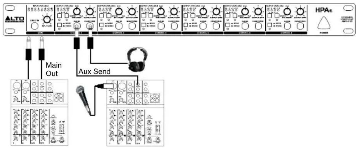
USING THE AUX INPUTS
You can also play back a signal to feed in a vocal microphone and then connect a mixer's aux send to HPA6's Aux Input. Use the Balance control to give the vocalist the desired mix between the voice and the playback signal. Then, adjust the Output Gain control to regulate the overall desired volume.
flowchart
graph TD
    A["ALTO"] --> B["Main Out"]
    B --> C["Aux Send"]
    C --> D["HPA6"]
    style A fill:#f9f,stroke:#333
    style D fill:#ccf,stroke:#333
Through the Aux Inputs, you can use the six channels of HPA6 independently to give individual mixes to six different musicians. Connect the Aux Sends or Subgroup outputs directly to the Aux Input of HPA6. Then rotate the Balance control on your HPA6 fully to the left. This will route only the AUX IN signal to the headphones.

flowchart
graph TD
    A["ALTO"] --> B["AUX Send 1"]
    A --> C["AUX Send 2"]
    A --> D["AUX Send 3"]
    A --> E["AUX Send 4"]
    A --> F["AUX Send 5"]
    A --> G["AUX Send 6"]
    H["HPA6"] --> B
    H --> C
    H --> D
    H --> E
    H --> F
    H --> G
    B --> I["Output: ALTO, HPA6"]
    C --> J["Output: ALTO, HPA6"]
    D --> K["Output: ALTO, HPA6"]
    E --> L["Output: ALTO, HPA6"]
    F --> M["Output: ALTO, HPA6"]
USING MULTIPLE HEADPHONES ON THE SAME CHANNEL
Each channel provides three headphone outputs. These jacks are all connected in parallel. For best results, please note the impedance information:
- When connecting one headphone to each channel, the minimum impedance of the headphone should be 100 ohms.
- When connecting two headphones to each channel, the minimum impedance of each headphone should be 200 ohms.
- When connecting three headphones to each channel, the minimum impedance of each headphone should be 300 ohms.
INSTALLATION AND CONNECTION
Read the following section carefully. Not paying attention to the input signal level, to the routing of the signal and to the assignment of the signal will result in unwanted distortion, a corrupted signal or no sound at all.
Power Connection
Use the same fuse as marked on the fuse holder near the power connector. Connect HPA6 to a standard power outlet using the enclosed power cable.
Audio Connection
The HPA6 uses balanced XLR and 1/4" TRS phones jack. It can be connected to other units in a variety of ways to support a vast range of applications without experiencing a signal loss.
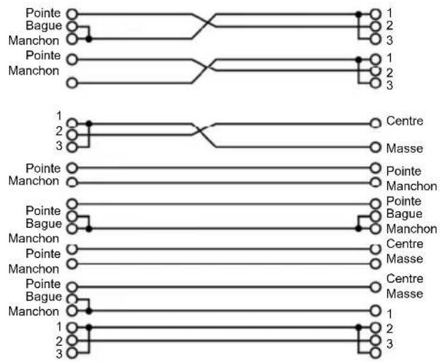
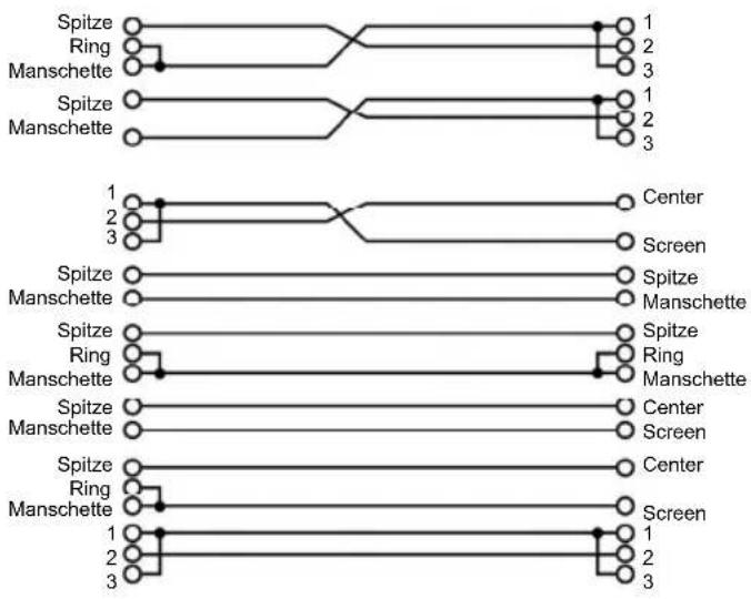
Wiring Configuration
XLR servo connectors can be wired in balanced and unbalanced modes. Please wire your systems according to the following examples:
• 1/4" Phone jack
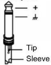
TS Type Unbalanced
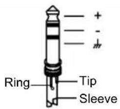
TRS Type Balanced
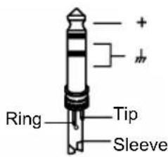
TRS Type Unbalanced
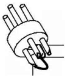
- XLR connector
natural_image
Simple line drawing of a plug with three pins and a curved arrow pointing to one pin (no text or symbols)Pin1 (±)
Pin2 (+)
Pin3 (-)
(Linked to Pin1 manually
XLR Type Unbalanced
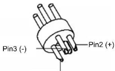
Pin1 (m)
XLR Type Balanced
• Balanced
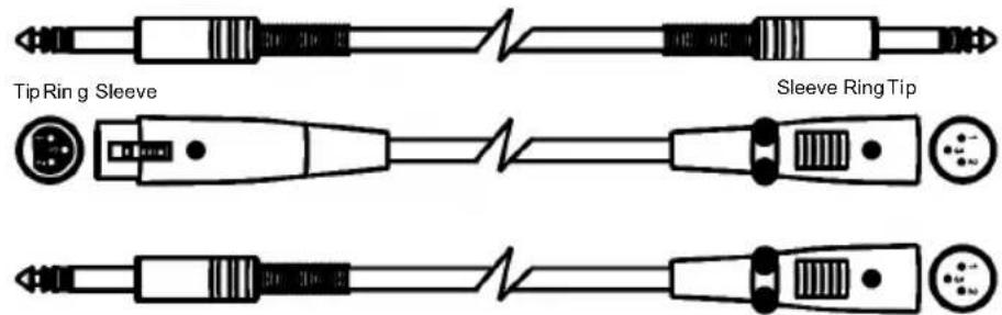
Tip Ring Sleeve

- Unbalanced


flowchart
graph TD
    subgraph Top
        A1["Tip"] --> B1["Ring"]
        A1 --> C1["Sleeve"]
        A2["Tip"] --> B2["Ring"]
        A2 --> C2["Sleeve"]
        A3["Tip"] --> B3["Ring"]
        A3 --> C3["Sleeve"]
        A4["Tip"] --> B4["Ring"]
        A4 --> C4["Sleeve"]
        A5["Tip"] --> B5["Ring"]
        A5 --> C5["Sleeve"]
        A6["1"] --> B6["Center"]
        A7["2"] --> B7["Screen"]
        A8["3"] --> B8["Screen"]
    end
    subgraph Bottom
        B1 --> C1
        B1 --> C2
        B1 --> C3
        B2 --> C4
        B2 --> C5
        B3 --> C6["Center"]
        B3 --> C7["Screen"]
        B4 --> C8["Center"]
        B4 --> C9["Screen"]
        B5 --> C10["Center"]
        B5 --> C11["Screen"]
        B6 --> C12["Center"]
        B6 --> C13["Screen"]
        B7 --> C14["Center"]
        B7 --> C15["Screen"]
        B8 --> C16["Center"]
        B8 --> C17["Screen"]
        B9 --> C18["Center"]
        B9 --> C19["Screen"]
        B10 --> C20["Center"]
        B10 --> C21["Screen"]
        B11 --> C22["Center"]
        B11 --> C23["Screen"]
        B12 --> C24["Center"]
        B12 --> C25["Screen"]
        B13 --> C26["Center"]
        B13 --> C27["Screen"]
        B14 --> C28["Center"]
        B14 --> C29["Screen"]
        B15 --> C30["Center"]
        B15 --> C31["Screen"]
        B16 --> C32["Center"]
        B16 --> C33["Screen"]
        B17 --> C34["Center"]
        B17 --> C35["Screen"]
        B18 --> C36["Center"]
        B18 --> C37["Screen"]
        B19 --> C38["Center"]
        B19 --> C39["Screen"]
        B20 --> C40["Center"]
        B20 --> C41["Screen"]
GUÍA DEL USUARIO (ESPAÑOL)
CONTENIDO DE LA CAJA
Tipo TS no balanceado

Tipo TRS balanceado

Type TRS symétrique

natural_image
Simple line drawing of a plug with three pins and a curved arrow indicating a pin (no text or symbols)Broche 1 (±)
Broche 2 (+)
Broche 3 (-)
natural_image
Simple line drawing of a multi-pin electrical connector (no text or symbols)Broche 1 (m)
Broche 2 (+)

- Asymétrique

flowchart
graph TD
    subgraph Top
        A["Pointe"] --> B["Bague"]
        B --> C["Manchon"]
        C --> D["Pointe"]
        D --> E["Manchon"]
        E --> F["1"]
        F --> G["2"]
        G --> H["3"]
        H --> I["1"]
        I --> J["2"]
        J --> K["3"]
    end
    subgraph Bottom
        L["Pointe"] --> M["Manchon"]
        M --> N["Pointe"]
        N --> O["Bague"]
        O --> P["Manchon"]
        P --> Q["Pointe"]
        Q --> R["Manchon"]
        R --> S["1"]
        S --> T["2"]
        T --> U["3"]
        U --> V["1"]
        V --> W["2"]
        W --> X["3"]
        X --> Y["Centre"]
        Z["Masse"] --> AA["Centre"]
    end
IMPIEGO DEGLI INGRESSI AUX
natural_image
Simple line drawing of a plug with three pins and a curved connector (no text or symbols)Pin1 (m)
Pin2 (+)
Pin3 (-)
natural_image
Pure electrical circuit lines without any symbolsSpitze Ring Manschette
Manschette Ring Spitze

natural_image
Pure electrical connector diagram without any text or symbols
natural_image
Pure electrical circuit lines without any symbolsSpitze Ring Manschette
Spitze
Ring
Manschette

Spitze
Ring
Manschette

- Unsymmetrisch

flowchart
graph TD
    A["Spitze"] --> B["Ring"]
    B --> C["Manschette"]
    C --> D["Spitze"]
    D --> E["Manschette"]
    E --> F["Spitze"]
    F --> G["Ring"]
    G --> H["Manschette"]
    H --> I["Spitze"]
    I --> J["Manschette"]
    J --> K["Spitze"]
    K --> L["Ring"]
    L --> M["Manschette"]
    M --> N["Spitze"]
    N --> O["Manschette"]
    O --> P["Spitze"]
    P --> Q["Manschette"]
    Q --> R["Spitze"]
    R --> S["Manschette"]
    S --> T["Spitze"]
    T --> U["Manschette"]
    U --> V["Spitze"]
    V --> W["Manschette"]
    W --> X["Spitze"]
    X --> Y["Manschette"]
    Y --> Z["Spitze"]
    Z --> AA["Manschette"]
    AA --> AB["Spitze"]
    AB --> AC["Manschette"]
    AC --> AD["Spitze"]
    AD --> AE["Manschette"]
    AE --> AF["Spitze"]
    AF --> AG["Manschette"]
    AG --> AH["Spitze"]
    AH --> AI["Manschette"]
    AI --> AJ["Spitze"]
    AJ --> AK["Manschette"]
GERBRUIKERSHANDLEIDING (NEDERLANDS)
INHOUD VAN DE DOOS
Connectors: XLR and 1/4"
Type: Electronically servo-balanced, RF-filtered
Impedance:
• Balanced : > 50 KΩ
• Unbalanced: > 25 KΩ
Max. Input Level: +21 dBu typical, balanced or unbalanced
AUX IN and DIRECT IN
Connectors: 1/4" TRS (tip=left, ring=right, sleeve=ground)
Impedance:
Unbalanced: > 25 KΩ
Max input level: +21 dBu, unbalanced
OUTPUT
Connectors: XLR and 1/4"
Type: balanced/unbalanced
Max. output level: +21 dBu balanced and unbalanced
PERFORMANCE
• Frequency response: 10 Hz to 50 kHz,+0/-3 dB
• Signal-to-Noise Ratio: >90 dB, unweighted
• Signal-to-Noise: Ref: +4 dBu, 22 Hz - 22 kHz
• THD: Ref: +4 dBu, 0.005%
POWER AMPLIFIER
• Max output power: +21 dBmW
• Min. output impedance: 100 Ω
- Max gain: +20 dB
POWER SUPPLY
Power Consumption: 14 watts
Power Supply: AC 120V, 60Hz
AC 230V - 240V, 50 Hz
Power connection: Standard IEC
DIMENSIONS
(W x D x H) 19" x 8.54" x 1.7"; 483 mm x 217 mm x 44 mm
WEIGHT
6.39 lbs.; 2.9 kg
www.altoprofessional.com
- HPA6
- USER GUIDE (ENGLISH)
- BOX CONTENTS
- INTRODUCTION
- FRONT PANEL CONTROLS
- REAR PANEL CONTROLS
- APPLICATIONS
- USING THE MAIN INPUT CONNECTORS
- USING THE AUX INPUTS
- USING MULTIPLE HEADPHONES ON THE SAME CHANNEL
- INSTALLATION AND CONNECTION
- Power Connection
- Audio Connection
- Wiring Configuration
- GUÍA DEL USUARIO (ESPAÑOL)
- CONTENIDO DE LA CAJA
- IMPIEGO DEGLI INGRESSI AUX
- GERBRUIKERSHANDLEIDING (NEDERLANDS)
- INHOUD VAN DE DOOS
- AUX IN and DIRECT IN
- OUTPUT
- PERFORMANCE
- POWER AMPLIFIER
- POWER SUPPLY
- DIMENSIONS
- WEIGHT
Brand : ALTO
Model : HPA6
Category : Processor