
MSB 24 - Brush cutter EINHELL - Free user manual and instructions
Find the device manual for free MSB 24 EINHELL in PDF.
| Product type | Petrol brush cutter |
| Brand | Einhell |
| Model | MSB 24 |
| Engine type | 2-stroke, air-cooled |
| Displacement | 24 cm³ |
| Power | 0.8 kW |
| Weight (dry) | 7 kg |
| Fuel tank capacity | 500 ml |
| Fuel/oil mixture | 40:1 |
| Cutting width (dual line) | 43 cm |
| Cutting width (cutting blade) | 23 cm |
| Cutting line diameter | 2.5 mm |
| Guide bar length | 142 cm |
| Ignition | Electronic |
| Spark plug | TORCH L7RTC |
| Transmission | Centrifugal clutch |
| Handle | "Bike" type (bicycle handle) |
| Safety devices | Protective cover, deflector with line cutter, exhaust guard, shoulder strap |
| Routine maintenance | Cleaning the air filter, replacing the fuel filter, adjusting the spark plug, sharpening the line cutter |
| Main spare parts | Line head, line spool, cutting blade (ref. 34.051.63), spark plug (TORCH L7RTC), air filter, fuel filter |
| Repairability | 2-year warranty, after-sales service by ISC GmbH or Einhell Benelux |
Frequently Asked Questions - MSB 24 EINHELL
User questions about MSB 24 EINHELL
0 question about this device. Answer the ones you know or ask your own.
Ask a new question about this device
Download the instructions for your Brush cutter in PDF format for free! Find your manual MSB 24 - EINHELL and take your electronic device back in hand. On this page are published all the documents necessary for the use of your device. MSB 24 by EINHELL.
USER MANUAL MSB 24 EINHELL
flowchart
graph TD
    A["A"] --> B["B"]
    B --> E["E"]
    E --> F["F"]
    F --> C["C"]
    C --> G["G"]
    G --> D["D"]
    D --> G
    style A fill:#f9f,stroke:#333
    style B fill:#ccf,stroke:#333
    style C fill:#cfc,stroke:#333
    style D fill:#fcc,stroke:#333
    style E fill:#ffc,stroke:#333
    style F fill:#cff,stroke:#333
    style G fill:#fcf,stroke:#333


natural_image
Close-up of a white electric shaver with a metal rod and labeled component B (no text or symbols beyond label)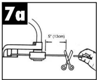


natural_image
Close-up of a hand using a white electric shaver on a tiled floor, no visible text or symbols


natural_image
Illustration of two people spraying water on a field, no text or symbols present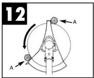
natural_image
Technical line drawing of a mechanical component with no visible text or symbols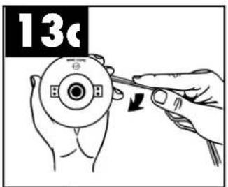

natural_image
Close-up of a white handheld device with black components and directional arrows, labeled '14a' in the top-left corner (no other text or symbols)

natural_image
Illustration of hands installing or adjusting a small component with a tool, labeled 'D' (no text or symbols on the diagram itself)


General Safety Rules
Meaning of symbols marked on the product

Read the user manual before using the machine

Wear a helmet, earplugs and safety goggles.

Keep other people out of the danger area.

Caution! Danger!

The arrows show the correct positions for your hands – do not adjust your hand position.

Caution! Hot surface!

The noise emissions comply with Directive 2000/14/EC

Danger from objects being thrown up by the machine

Maximum speed

Wear gloves to protect your hands

Wear safety boots to protect against electric shock
WARNING! When using gas tools, basic safety precautions, including the following, should always be followed to reduce the risk of serious personal injury and/or damage to the unit.
Read all these instructions before operating this product and save these instructions.
This power unit can be dangerous! Operator is responsible for following unit manual instructions and warnings. Read entire operator's manual before using unit! Be thoroughly familiar with the controls and the proper use of the unit. Restrict the use of this unit to persons who read, understand, and follow unit, manual instructions and warnings. Never allow children to operate this unit.
⚠️ DANGER: Never use blades, wire or flailing devices. Unit is designed for line trimmer use only. Use of any other accessories or attachments will increase the risk of injury.

⚠ WARNING: Keep children, bystanders, and animals 50 feet (15 meters) away. If approached stop unit immediately.
-
Wear close fitting, tough work clothing that will provide protection, such as long slacks or trousers, safety work shoes, heavy duty work gloves, hard hat, a safety face shield, or safety glasses for eye protection and a good grade of ear plugs or other sound barriers for hearing protection.
-
Store in a safe place. Open fuel cap slowly to release any pressure which may have formed in fuel tank. To prevent a fire hazard, move at least 10 feet (3 meters) from fueling area before starting.
-
Turn unit off before setting it down.
-
Always hold unit firmly with both hands, the thumb and fingers encircling the handles.
-
Keep all screws and fasteners tight. Never operate your equipment when it is improperly adjusted or not completely and securely assembled.
-
Keep handles dry, clean and free of fuel mixture.
-
Keep stringhead as close to ground as practical. Avoid hitting small objects with stringhead. When cutting on a slope, stand below stringhead. NEVER cut or trim on a hill or slope, etc. if there is the slightest chance of slipping, sliding or losing firm footing.
-
Check area you will be trimming for debris that may be struck or thrown during operation.
-
Keep all parts of your body and clothing away from stringhead when starting or running
engine. Before starting engine, make sure stringhead will not come in contact with any obstacle.
- Stop engine before examining cutting line.
- Store equipment away from possible flammable materials, such as gas-powered water heaters, clothes dryers, or oil-fired furnaces, portable heaters, etc.
- Always keep the debris shield, stringhead, and engine free of debris build-up.
- Operation of equipment should always be restricted to mature and properly instructed individuals.
- You must comply with the latest fire safety directives and the state and the fire prevention regulations in force in your area and country. The user bears full responsibility for using the machine. Your machine is fitted with a spark protection grille. A spare grille can be obtained from ISC GmbH.
SAFETY WHEN HANDLING THE BLADE
- FOLLOW ALL WARNINGS and instructions for using the machine and for installing the blade.
- The blade may suddenly jump away out of control if it comes up against objects which it cannot cut through. This may result in the amputation of arms or legs. Keep onlookers and animals at least 15 m away from where you are working. If the machine strikes a foreign body, stop the engine immediately and bring the blade to a standstill. Check the blade for signs of damage. Always replace the blade if it is bent or torn.
- THE BLADE WILL THROW UP OBJECTS AT HIGH SPEED: This may cause blinding or injuries. Always wear eye, face and leg protection. Remove all objects from the working area before using the blade. Keep other people and animals at least 15 m away from the machine in all directions.
- Check your machine and other equipment carefully for signs of damage. Do not use the machine unless all the blade mountings have been installed correctly.
- THE BLADE WILL SLOW DOWN AND STOP IF YOU RELEASE THE THROTTLE VALVE (gas lever). While it is slowing down, the blade can still cut you or onlookers. Before you carry out any work on the blade, switch off the engine and make sure that the blade has stopped.
- DANGER ZONE WITH A DIAMETER OF 20 METERS. Onlookers may suffer blindness or injuries. Keep onlookers and animals at least 15 m away from where you are working.
WHAT NOT TO DO
- DO NOT USE ANY OTHER FUEL than that recommended in your manual. Always follow instructions in the Fuel and Lubrication section of this manual. Never use gasoline unless it is properly mixed with 2-cycle engine lubricant. Permanent damage to engine will result, voiding manufacturer's warranty.
- DO NOT SMOKE while refueling or operating equipment.
- DO NOT OPERATE UNIT WITHOUT A MUFFLER and properly installed muffler shield.
- DO NOT TOUCH or let your hands or body come in contact with the muffler. Hold unit with thumbs and fingers encircling the handles.
- DO NOT OPERATE UNIT IN AWKWARD POSITIONS, off balance, outstretched arms, or one-handed. Always use two hands when operating unit with thumbs and fingers encircling the handles.
- DO NOT RAISE STRINGHEAD above ground level while unit is operating. Injury to operator could result.
- DO NOT USE UNIT FOR ANY PURPOSES OTHER than trimming lawn or garden areas.
- DO NOT OPERATE UNIT FOR PROLONGED PERIODS. Rest periodically.
- DO NOT OPERATE UNIT WHILE UNDER THE INFLUENCE OF ALCOHOL OR DRUGS.
- DO NOT OPERATE UNIT UNLESS DEBRIS SHIELD AND/OR GUARD IS INSTALLED AND IN GOOD CONDITION.
- DO NOT ADD, REMOVE OR ALTER ANY COMPONENTS OF THIS PRODUCT. Doing so could cause personal injury and/or damage the unit voiding the manufacturer's warranty.
- DO NOT operate your unit near or around flammable liquids or gases whether in or out of doors. An explosion and/or fire may result.
- DO NOT USE ANY OTHER CUTTING TOOLS. For your own safety only use the accessories and additional equipment specified in the operating manual or recommended or specified by the manufacturer. The use of tools or accessories other than those recommended in the operating manual or catalog may place you in danger of personal injury.
GB
Specifications
| MSB 24 | |
| Engine Type Air-cooled, 2-Cycle, Chrome Cylinder | |
| Displacement 24 cm | 3 |
| Power: 0,8 kW | |
| Dry Weight 7 kg | |
| Fuel Capacity 500 ml | |
| Handle Length 142 cm | |
| Twin Line Cutting Width 43 cm | |
| Line diameter 2,5 mm | |
| Blade cutting width 23 cm | |
| Handle Bike handle | |
| Ignition Electronic | |
| Spark plug Torch L7RTC | |
| Drive Centrifugal clutch |
General identification
-
STRINGHEAD
-
CUTTER LINE (34.051.72)
-
DEBRIS SHIELD
-
GRASS CUTTING BLADE (34.051.63)
-
BLADE GUARD
-
THROTTLE TRIGGER
-
IGNITION OFF SWITCH
-
SAFETY TRIGGER
-
CHOKE LEVER KNOB
-
STARTER ROPE HOUSING
-
FUEL TANK
-
AIR FILTER COVER
-
STARTER HANDLE
-
MUFFLER SHIELD
-
PRIMER BULB
-
DEBRIS SHIELD NUT & BOLT & WASHER
-
COUPLING
-
SHOULDER STRAP
-
EYELET FOR SHOULDER STRAP
NOTE: DO NOT use blades on these models.
SAFETY EQUIPMENT
The numbers that precede the descriptions correspond to the numbers on the previous page to enable you to identify the safety equipment more easily
3 / 5 BLADE GUARD: This must be fitted at all times to prevent the user being injured by objects thrown up by the machine. The blade fitted in
the hood guard 3 also cuts the cutting line to the perfect length automatically.
16 EXHAUST GUARD: This prevents hands, body and/or inflammable material coming into contact with the hot exhaust.
ASSEMBLY INSTRUCTIONS
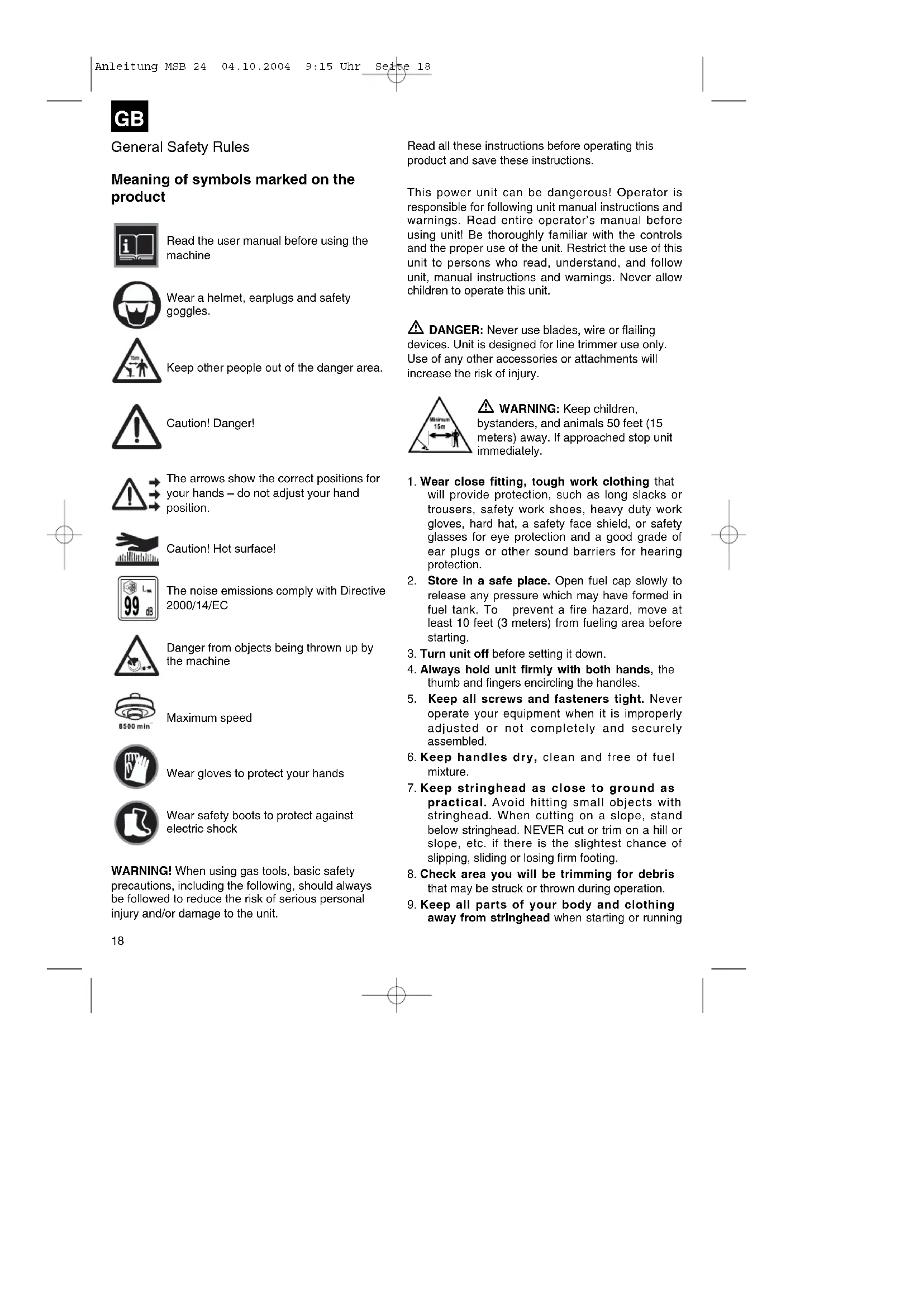
FITTING THE "Bike" HANDLE (Fig. 1c - 1d)
- To fasten the handle to the machine you will need the following parts from the kit: "Bike" handle (A), mounting (B), clip (C) and screws (D).
- Position the handle mounting (B) on the shaft in the direction indicated by the arrow (see warning sticker) place the clip (C) over the shaft and tighten the two screws (D).
- Place the "Bike" handle (A) on the mounting, fit the other clip (C) above the guide shaft and secure it with the other two screws (D).
- Secure the cable going to the handle with the cable tie (E).
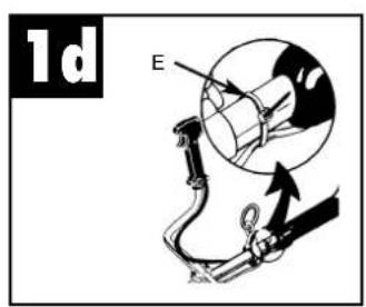
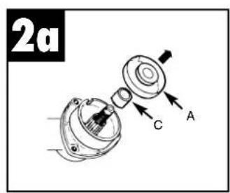
Fitting the blade guard (Fig. 2a - 2b)
- Take the gearbox collar (A) off the thread on the gearbox casing shaft.
- Place the guard on to the gearbox casing and line up the fastening holes. Insert the screws (B) as shown in the figure and tighten them.
- Insert the gearbox collar (A) again. Ensure that the collar spacer (C) is in the correct position, otherwise the collar will rub on the gearbox casing.
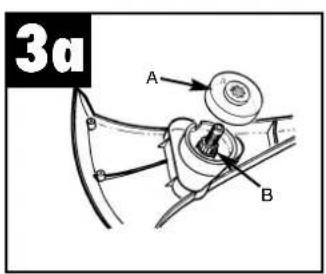
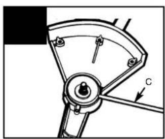
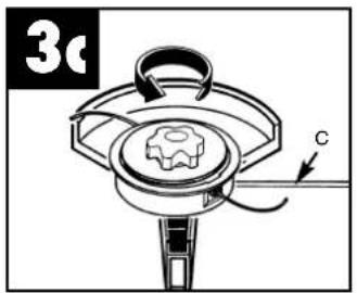
FITTING THE LINE HEAD (Fig. 3a - 3c)
- Insert the gearbox collar (A) and ensure that the collar spacer (B) is in the correct position.
- Insert the retaining pin (C) and screw the line head to the shaft. Tighten the line head by hand only.
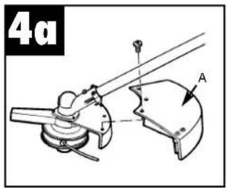
Fitting the cutting line guard (Fig. 4A)
Turn the machine over and fit the cutting line guard (A) as shown.
CAUTION: The cutting line guard must be fitted to ensure that the cutting line is cut to the correct length so as to protect the user.
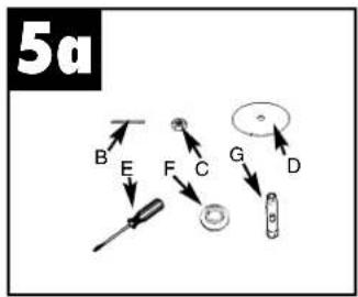
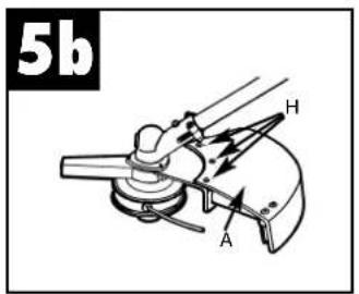
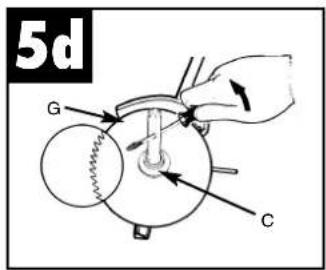
FITTING THE BLADE (Fig. 5a - 5d)
CAUTION: Never use the machine if the blade is bent, broken or has teeth missing. Replace a damaged blade immediately.
CAUTION: Only use the machine with a blade if the metal blade guard has been fitted correctly. Never use the machine with a defective blade guard.
CAUTION: Always wear thick gloves for handling and fitting a blade.
- To fit the blade you will need the following parts: Retaining pin (B), retaining nut (C), blade (D), screwdriver (not supplied) (E), flange (F), socket (G).
- Undo the three screws (H). Remove the cutting line guard (A). Use the retaining pin to prevent the collar turning whilst you remove the line head (turn it CLOCKWISE).
- Leave the retaining pin (B) in position.
WARNING: Ensure that the hole through the center of the blade fits the size of the collar shaft.
- Fit the blade (D) so that its teeth point CLOCKWISE as shown.
- Fit the flange (F) so that its FLAT SIDE is against the blade. Important: Ensure that the blade is centered on the collar shaft.
- Tighten the nut (C) by turning it ANTI-CLOCKWISE with the socket (G). Then remove the retaining pin.
Fuel and lubrication
- Fuel
Use regular grade unleaded gasoline mixed with 2-cycle engine oil for best results. Use mixing ratios in
Section FUEL MIXING TABLE.
⚠ Warning: Never use straight gasoline in your unit. This will cause permanent engine damage and void the manufacturer's warranty for that product. Never use a fuel mixture that has been stored for over 90 days.
⚠ Warning: Do not use any 2-cycle oil product with a recommended mixing ratio of 100:1. If insufficient lubrication is the cause of engine damage, it voids the manufacturer's engine warranty.
• MIXING FUEL
Mix fuel 2 cycle oil in an approved container. Use mixing table for correct ratio of fuel to oil. Shake container to ensure through mix.
⚠ Warning: Lack of lubrication voids engine warranty. Gasoline and oil must be mixed at 40:1.
- Fuel Mixing Table
Gasoline Lubricant
5 Liters 125 ml (cc)
Mixing Procedure 40 Parts Gasoline to
1 part Lubricant
1 ml = 1 cc
RECOMMENDED FUELS
Some conventional gasolines are being blended with oxygenates such as alcohol or an ether compound to meet clean air standards. Your engine is designed to operate satisfactorily on any gasoline intended for automotive use including oxygenated gasolines.
OPERATING INSTRUCTIONS
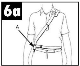
- Shoulder strap
WARNING: Always use the shoulder strap to support the machine. Attach the strap to the machine as soon as you start the engine and the engine is idling. Switch off the engine before taking off the shoulder strap.
- Place the shoulder strap over your left shoulder.
- Hook the attachment hook (A) into the eyelet (B) (Fig. 6A and Fig. 6B).
- Adjust the length of the shoulder strap so that the gearbox head is parallel to the ground. Then swing the machine a few times without starting the engine to find the perfect length for the shoulder strap.
Note: Detach the shoulder strap from the machine before you start the engine.
GB
• STARTING THE ENGINE WHEN IT IS COLD
PLEASE NOTE: To minimize the stress on the engine when starting and warming the engine, cut the excess cutting line to a length of 13 cm (Fig. 7A).
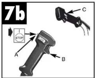
- Set the ignition switch to "RUN (I)" (Fig. 7B).
- Fix the gas lever. Press the "Lock off" switch (A) downwards. Then press the gas lever (B) and slide the locking switch (C) downwards at the same time. The gas lever will lock on full (Fig. 7b).
- The machine has a choke that can be set to one of three positions: CHOKE “→” START“↘” and RUN “↑”. Set the choke lever to CHOKE “→” (Fig. 7i).
- To start the engine, spray fuel into the carburetor. Press the tickler (A) ten times (Fig. 7e).
- Pull the starter cord a little way out until you feel resistance (approx. 10 cm) (Fig. 7f). To generate a strong ignition spark the cord must be pulled quickly and smoothly. Pull the starter cord four times quickly and powerfully.
- Set the choke lever to START" (Fig. 7h).
- Pull the starter cord a further four times with the gas lever set to full.
- If the engine starts, remain on START" for 10 seconds.
- Set the choke to RUN" (Fig. 7d).
- If the engine does not start repeat steps 1 to 8.
PLEASE NOTE: If the engine does not start after you have made several attempts please refer to the section entitled "Troubleshooting on the engine".
NOTE: Always pull starter rope straight out. Pulling starter at an angle will cause rope to rub against the eyelet. This friction will cause the rope to fray and wear more quickly. Always hold starter handle when rope retracts. Never allow rope to snap back from extended position. This could cause rope to snag or fray and also damage the starter assembly.
• STARTING THE ENGINE WHEN IT IS WARM
- Place the machine on a hard, flat surface.
- Set the ignition switch to RUN (I) (Fig. 7b).
- Set the choke to the START" position (Fig. 7h).
- Hold the gas lever tightly and press the trigger FULLY.
- Pull the starter cord quickly until the engine starts. Do not pull the cord more than six times. Hold the gas lever FULLY pressed until the engine is running smoothly.
- Set the choke to RUN" & and pull the starter cord
a further five times if the engine does not start. If the engine still does not start it is probably flooded with gasoline. Wait for five minutes and then try again with the choke set to RUN “↑” and with the gas lever fully pressed.
• TO STOP ENGINE
Release throttle trigger. Let engine return to idle. Push and hold ignition stop switch until engine stops (Fig. 7b).
Trimming Instructions
• ADDITIONAL SAFETY PRECAUTIONS
Before operating your unit, review ALL SAFETY PRECAUTIONS in this manual.
WARNING / CAUTION
- I F UNFAMILIAR WITH TRIMMING techniques, practice the procedures with ENGINE in "OFF" position.
- ALWAYS CLEAR WORK area of debris such as cans, bottles, rocks, etc. Striking objects can cause serious injury to operator or bystanders and also damage equipment. If an object is accidentally hit, immediately TURN ENGINE OFF and examine equipment. Never operate unit with damaged or defective equipment.
- ALWAYS TRIM OR CUT AT HIGH ENGINE SPEEDS. Do not run engine slowly at start or during trimming operations.
- DO NOT use equipment for purposes other than trimming or mowing weeds.
- NEVER raise stringhead above knee height during operation.
- DO NOT operate unit with other people or animals in the immediate vicinity. Allow a minimum of 50 feet (15 meters) between operator and other people and animals when trimming or mowing. Allow a distance of 100 feet (30 meters) between operator and other people and animals when SCALPING with stringhead cutter.
- IF OPERATING UNIT ON A SLOPE, stand below the cutting attachment. DO NOT OPERATE on a slope or hilly incline if there is the slightest chance of slipping or losing your footing.
• STRINGHEAD LINE RELEASE
⚠ WARNING: DO NOT use steel wire or plastic-coated steel wire of any kind with your stringhead. Serious operator injury can result.
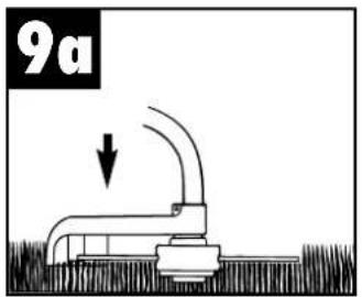
To release fresh line, run engine at full throttle and
"bump" stringhead against lawn. Line will automatically release. The knife in debris shield will trim excess line (Fig. 9A).
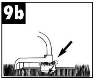
CAUTION: Periodically remove weed wrap to prevent overheating the drive shaft. Weed wrap occurs when strands of weed become entangled around the shaft beneath the debris shield (Fig. 9B). This condition prevents the shaft from being properly cooled. Remove weed wrap with screwdriver or similar
• TRIMMING PROCEDURES
When properly equipped with a debris shield and stringhead, your unit will trim unsightly weeds and tall grass in those hard-to-reach areas - along fences, walls, foundations and around trees. It can also be used for scalping to remove vegetation down to the ground for easier preparation of a garden or to clean out a particular area.
NOTE: Even with care, trimming around foundations, brick or stone walls, curves, etc., will result in above normal string wear.
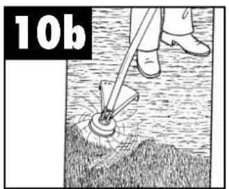
TRIMMING / MOWING
Swing trimmer with a sickle-like motion from side to side. Do not tilt the stringhead during the procedure. Test area to be trimmed for proper cutting height. Keep stringhead at same level for even depth of cut (Fig. 10A).
CLOSER TRIMMING
Position trimmer straight ahead with a slight tilt so bottom of stringhead is above ground level and string contact occurs at proper cutting point. Always cut away from operator. Do not pull trimmer in toward operator.
FENCE / FOUNDATION TRIMMING
Approach trimming around chain link fences, picket fences, rock walls and foundations slowly to cut close without whipping string against the barrier. If the string comes in contact with rock, brick walls, or foundations, it will break or fray. If string snags fencing, it will snap off.
TRIMMING AROUND TREES
Trim around tree trunks with a slow approach so string does not contact bark. Walk around the tree trimming from left to right. Approach grass or weeds with the tip of the string and tilt stringhead slightly forward.
WARNING: Use extreme caution when
SCALPING. Keep a distance of 100 feet (30 meters) between operator, other people and animals during these operations.
SCALPING
Scalping refers to removal of all vegetation down to the ground. To do this, tilt the stringhead to about a 30 degree angle to the left. By adjusting the handle you will have better control during this operation. Do not attempt this procedure if there is any chance flying debris could injure operator, other people or cause damage to property. (Fig. 10B)
Cutting with blades
WARNING: Before you use this machine with a blade, check that it has been fitted correctly. Follow all the instructions set out in the section entitled "Safety instructions for undergrowth/grass cutting blades" in this operating manual.
CUTTING WITH BLADES
Whenever you are cutting with a blade you must wear eye protection and protective clothing. Always use the shoulder strap when working with the blade.
WORKING WITH WEED-CUTTING BLADES (supplied, Art. No. 34.051.63) MOWING WEEDS
Mowing means moving the blade in a horizontal curve from one side to the other. This is very effective for grass-like weeds and small undergrowth. It is not suitable for cutting large, tough weeds or woody vegetation (Fig. 11).
CAUTION: Do not use weed-cutting blades for cutting scrub or young trees.
SAWING
The BMST 24 is not designed for sawing.
JAMMING
Very thick vegetation, such as young trees or thick scrub may jam the blade and bring it to a standstill. Prevent the blade from jamming by anticipating the direction in which the scrub leans and cut it from the opposite side. If the blade jams while cutting, switch off the engine immediately. Hold the machine level so that the blade does not jump or break while you push the young tree away from the cut to free the blade.
TO PREVENT RECOIL
When using metal cutting tools (grass blades, thicket knives) there is a risk that the machine will recoil if the tool strikes a solid object (tree truck, branch, tree stump, stone or the like). In this case the machine will jump backwards in the opposite direction to which the tool is rotating. This may lead to a loss of control of the tool and risk of injury to the user and onlookers.
GB
Do not use metal cutting tools near fences, metal posts, boundary stones or foundations.
The safety blade is designed to reduce recoil if the blade strikes a hard, solid object. To cut thick stalks, place it in position (A), see Fig. 12, to prevent recoil.
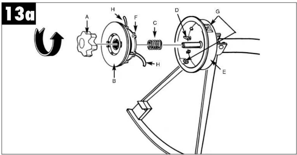
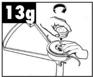
Fig 13A
A. KNOB
B. SPOOL
C. SPRING
D. SPINDLE
E. HOUSING
F. SLOTS
G. EYELETS
H. CUTTER LINE
- REPLACING CUTTER LINE
- Turn knob (A) COUNTERCLOCKWISE and remove (Fig. 13A). User knob spanner supplied.
- Remove spool (B) and spring (C) from spindle (D).
- Remove any remaining cutter line (H).
- Double a 14" (4.3m) length of .080" (2mm) cutter line. Place the looped center in one of the slots of the spool divider (Fig. 13B).
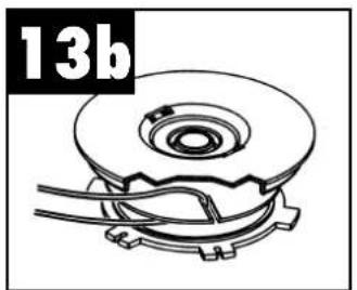
- Wind cutter line clockwise as shown in illustration (Fig. 13C), keeping tension, with each half separated by the spool divider. Wind to within 6" (15cm) of the ends.
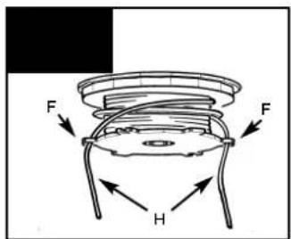
- Lock each end of line (H) into a slot (F) on opposite sides of the spool (Fig. 13D).
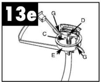
- Install the spring (C) over the spindle (D). Insert each end of the line through an eyelet (G) in the housing (E) (Fig. 13E).
- Lower the spool into the housing (E) while feeding the line through the eyelets (G). Ensure the spring seats itself into the spool (Fig. 13E).
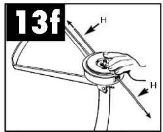
- Once the spool is in place, apply pressure on the spool compressing the spring. Pull each end of the line (H) sharply to unlock the line from the slots (Fig. 13F).
- Continue to apply pressure to the spool until the knob can be threaded CLOCKWISE onto the spindle. Tighten the knob securely by hand only (Fig. 13G).
- Trim the excess line to approximately 5" (13cm). This will minimize load on engine during starting and warm-up (Fig. 7A).
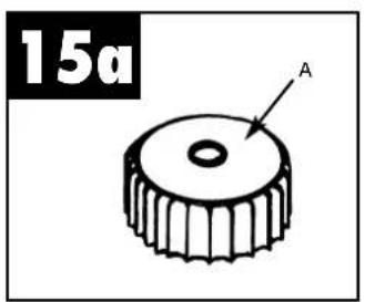
• AIR FILTER
⚠️ Caution: Remove fuel from unit and store in approved container before starting this procedure.
Open fuel cap slowly to release any pressure which may have formed in fuel tank.
To Clean Air Filter: (fig 14a - 14c)
- Remove 3 screws (A) holding air filter cover in place, pull out choke lever knob (B) remove cover (C) and lift filter (D) from air box.
- Wash filter in soap and water. DO NOT USE GASOLINE!
- Air dry filter.
- Reinstall filter.
NOTE: Replace filter if frayed, torn, damaged or unable to be cleaned.
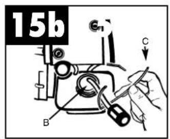
• FUEL CAP / FUEL FILTER
⚠️ Caution: Remove fuel from unit and store in approved container before starting this procedure. Open fuel cap slowly to release any pressure which may have formed in fuel tank.
NOTE: Keep vent (A) on fuel cap clean of debris (Fig.15A).
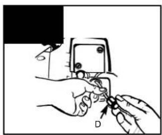
- Lift fuel line and filter (B) out of tank. A steel wire (C) with a hook or a paper clip works well (Fig. 15B).
- Pull off with a twisting motion (Fig. 15C).
- Replace fuel filter (D).
NOTE: Never operate the trimmer without the fuel filter. Internal engine damage could result!
• CARBURETOR ADJUSTMENT
The carburetor was pre-set at the factory for optimum performance. If further adjustments are necessary, please take your unit to the nearest Authorized Service Center.
- SPARK PLUG
- Spark plug gap = .025" (.635mm) (Fig. 16).
- Torque to 105 to 130 inch pounds (12 to 15 N•m). Connect spark plug boot.
• RADIO INTERFERENCE SUPPRESSION MODULE
- To replace the radio interference suppression module (A) (Fig. 18) lift the module out of its holder with a pair of needle pliers.
- To position the new radio interference suppression module push it into the holder with the needle pliers slightly open.
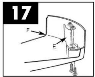
• DEBRIS SHIELD KNIFE SHARPENING
GB
- Remove cutter knife (E) from debris shield (F) (Fig. 17).
- Place knife in a bench vise. Sharpen knife using a flat file, being careful to maintain the angle of cutting edge. File in one direction only.
- STORING A UNIT
⚠ Warning: Failure to follow these steps may cause varnish to form in the carburetor and difficult starting or permanent damage following storage.
- Perform all the general maintenance recommended in the Maintenance Section of your User Manual.
- Clean exterior of engine, drive shaft assembly, debris shield and stringhead.
- Drain fuel from the fuel tank.
- After fuel is drained, start engine.
- Run engine at idle until unit stops. This will purge the carburetor of fuel.
- Allow engine to cool (approx. 5 minutes).
-
Using a spark plug wrench, remove the spark plug.
-
Pour 1 teaspoon of clean 2-cycle oil into the combustion chamber. Pull starter rope slowly several times to coat internal components. Replace spark plug.
- Store unit in a cool, dry place away from any source of ignition such as an oil burner, water heater, etc.
- Do not transport and store the trimmer with the blade fitted unless the supplied transport guard is also fitted.
- REMOVING A UNIT FROM STORAGE
- Remove spark plug.
- Pull starter rope briskly to clear excess oil from combustion chamber.
- Clean and gap spark plug or install a new spark plug with proper gap.
- Prepare unit for operation.
- Fill fuel tank with proper fuel / oil mixture. See Fuel and Lubrication Section.
Trouble shooting the engine
| PROBLEM | PROBABLE CAUSE | CORRECTIVE ACTION |
| Unit won't start or starts but will not run. | Incorrect starting procedures. | Follow instructions in the User Manual. |
| Incorrect carburetor mixture adjustment setting. | Have carburetor adjusted by an Authorized Service Center. | |
| Fouled spark plug | Clean / gap or replace plug. | |
| Fuel filter plugged. | Replace fuel filter. | |
| Unit starts, but engine has low power. | Incorrect lever position on choke. | Move to RUN position. |
| Remove, clean and reinstall filter. | ||
| Dirty air filter. | Have carburetor adjusted by an Authorized Service Center. | |
| Incorrect carburetor mixture adjustment setting. | ||
| Engine hesitates. | Incorrect carburetor mixture adjustment setting. | Have carburetor adjusted by an Authorized Service Center. |
| No power under load. | Incorrectly gapped spark plug. | Clean / gap or replace plug. |
| Runs erratically. | ||
| Smokes excessively. | Incorrect carburetor mixture adjustment setting. | Have carburetor adjusted by an Authorized Service Center. |
| Incorrect fuel mixture. | Use properly mixed fuel (40:1 mixture). |
F
⚠ WAARSCHUWING : Hou
- DRAADKOP
- SNIJDRAAD (34.051.72)
- BESCHERMKAP
TECHNISCHE GEGEVENS
⚠ WAARSCHUWING / VOORZICHTIG
UNDERHÅLLSFÖRESKRIFTER
Bild 13A
A. KORSHANDTAG
B. SPOLE
C. FJÄDER
D. SPINDEL
E. KÅPA
F. SPÅR
G. ÖGLOR
H. TRIMMERTRÅD
• BYTA UT TRIMMERTRÅDEN
POPIS PŘÍSTROJE (OBR. 1A)
- STRUNOVÁ HLAVA
- STRUNA (34.051.72)
- OCHRANNÝ KRYT
- ŘEZNÝ KOTOUČ NA TRÁVU (34.051.63)
- OCHRANNÝ KRYT
- PÁČKA ŠKRTICÍ KLAPKY
- VYPÍNAČ ZAPALOVÁNÍ
- BEZPEČNOSTNÍ SPÍNAČ
- PÁČKA SYTIČE
- KRYT STARTÉRU
- PALIVOVÁ NÁDRŽ
- VÍČKO VZDUCHOVÉHO FILTRU
- RUKOJEŤ STARTÉRU
- OCHRANA VÝFUKU
- PÁČKA ČERPÁNÍ
- MATICE A ČEP OCHRANNÉHO KRYTU*
- PŘIPOJOVACÍ SPOJKA
- POPRUH NA NOŠENÍ PŘES RAMENO
- ÚCHYT PRO POPRUH NA NOŠENÍ PŘES
RAMENO
5 litrov 125 ml (cc)
KOSENIE OKOLO STROMOV
KOSENIE TESNE NAD ZEMOU
POKYNY NA ÚDRŽBU obr. 13A
A. GOMBÍK
B. CIEVKA
C. PRUŽINA
D. HRIADEL
E. PUZDRO
F. ZÁREZY
G. OČKÁ
H. REZACIE VLÁKNO
• VÝMENA REZACIEHO VLÁKNA
The undersigned declares in the name of the company that the product is in compliance with the following guidelines and standards.
Eschenstraße 6 · D-94405 Landau/Isar (Germany)
Info-Tel. 0180-5 120 509 • Telefax 0180-5 835 830
The product described in these instructions comes with a 2-year warranty covering defects. This 2-year warranty period begins with the passing of risk or when the customer receives the product.
For warranty claims to be accepted, the product has to receive the correct maintenance and be put to the proper use as described in the operating instructions.
Your statutory rights of warranty are naturally unaffected during these 2 years.
This warranty applies in Germany, or in the respective country of the manufacturer's main regional sales partner, as a supplement to local regulations. Please note the details for contacting the customer service center responsible for your region or the service address listed below.
① CERTIFICATO DI GARANZIA
Technical changes subject to change
Unit 5 Morpeth Wharf
Twelve Quays
Birkenhead, Wirral
CH 41 1NG
Tel. 0151 6491500, Fax 0151 6491501
⑤ ABC EN CIEL ELECTRONIQUE
ZA BP 16
F-89000 ST GEORGES/Baulche
Resp. SAV: Oliver DEMEAUX
Technical & Commercial Company
12, Papastratou & Asklipiou Str.
GR 18545 Piräus
Tel 0210 4136155, Fax 0210 4137692
RUS Bermas, Moscow
Altufyevskoe shosse, 2A
RUS-127273 Moscow
Tel. 095 5401750 (central office)
Tel. 095 9033761 (Repair center Moscow)
Tel. 812 2240544 (Repair center St. Petersburg)
LT Dirbita
Metalo str. 23
LT-02190 Vllnlus
Tel 05 2395769, Fax 05 2395770
EST AS Baltoil
Roiu alev
Haaslava vald
EE-62102 Tartu
Tel 07 301 700, Fax 07 301 701
UAE Halai Trading Co. LLC
POB 9282, Nakheel Rd. Deira, Shop No. 15
UAE-Dubal
Tel. 04 2279554, Fax 04 2217686
IR Alborz Abzar Co. Ltd.
No. 111, Bastan Passage, Imam Khomeini Ave.
IR-11146 Teheran
Tel 021 6716072, Fax 021 6727177
Bih Einhell BiH d.o.o.
Poslovni Centar 96
BA-72250 Vitez
Tel 030 717250, Fax 030 717255
ZA Eurasia Industrial and Automotive Supply
- Bessemer Str.
Duncanville
ZA-Vereeniging 1939
Tel 016 455 571 2, Fax 016 455 571 6
BY Svyaz Prominvest Ltd.
207-11, Skariny av.
BY-220023 Minsk
Tel 017 2642777, Fax 017 2642591
D
The reprinting or reproduction by any other means, in whole or in part, of documentation and papers accompanying products is permitted only with the express consent of ISC GmbH.
F


- General Safety Rules
- Meaning of symbols marked on the product
- SAFETY WHEN HANDLING THE BLADE
- WHAT NOT TO DO
- GB
- General identification
- SAFETY EQUIPMENT
- ASSEMBLY INSTRUCTIONS
- FITTING THE "Bike" HANDLE (Fig. 1c - 1d)
- Fitting the blade guard (Fig. 2a - 2b)
- FITTING THE LINE HEAD (Fig. 3a - 3c)
- Fitting the cutting line guard (Fig. 4A)
- FITTING THE BLADE (Fig. 5a - 5d)
- WARNING: Ensure that the hole through the center of the blade fits the size of the collar shaft.
- Fuel and lubrication
- - Fuel
- Section FUEL MIXING TABLE.
- • MIXING FUEL
- - Fuel Mixing Table
- Gasoline Lubricant
- RECOMMENDED FUELS
- OPERATING INSTRUCTIONS
- - Shoulder strap
- • STARTING THE ENGINE WHEN IT IS COLD
- • STARTING THE ENGINE WHEN IT IS WARM
- • TO STOP ENGINE
- Trimming Instructions
- • ADDITIONAL SAFETY PRECAUTIONS
- WARNING / CAUTION
- • STRINGHEAD LINE RELEASE
- • TRIMMING PROCEDURES
- TRIMMING / MOWING
- CLOSER TRIMMING
- FENCE / FOUNDATION TRIMMING
- TRIMMING AROUND TREES
- SCALPING
- Cutting with blades
- WORKING WITH WEED-CUTTING BLADES (supplied, Art. No. 34.051.63) MOWING WEEDS
- SAWING
- JAMMING
- TO PREVENT RECOIL
- Do not use metal cutting tools near fences, metal posts, boundary stones or foundations.
- Fig 13A
- - REPLACING CUTTER LINE
- • AIR FILTER
- To Clean Air Filter: (fig 14a - 14c)
- • FUEL CAP / FUEL FILTER
- • CARBURETOR ADJUSTMENT
- - SPARK PLUG
- • RADIO INTERFERENCE SUPPRESSION MODULE
- - STORING A UNIT
- - REMOVING A UNIT FROM STORAGE
- F
- ⚠ WAARSCHUWING / VOORZICHTIG
- UNDERHÅLLSFÖRESKRIFTER
- Bild 13A
- • BYTA UT TRIMMERTRÅDEN
- POPIS PŘÍSTROJE (OBR. 1A)
- KOSENIE OKOLO STROMOV
- KOSENIE TESNE NAD ZEMOU
- POKYNY NA ÚDRŽBU obr. 13A
- • VÝMENA REZACIEHO VLÁKNA
- ① CERTIFICATO DI GARANZIA
- 207-11, Skariny av.
- D
Brand : EINHELL
Model : MSB 24
Category : Brush cutter