
H21 Z - Bike rack Uebler - Free user manual and instructions
Find the device manual for free H21 Z Uebler in PDF.
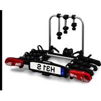
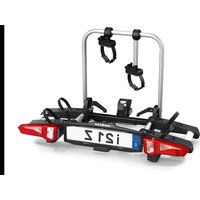
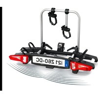
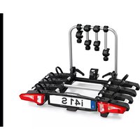
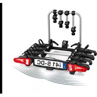
| Product Type | Towbar bike rack for 2 bikes |
| Brand | Uebler |
| Model | H21 Z |
| Reference | 18170 |
| Maximum load capacity | 75 kg (nose weight ≥ 78 kg) |
| Net weight | Approx. 18 kg |
| Maximum payload | 57 kg (if nose weight 75 kg) |
| Maximum weight per bike | 30 kg |
| Max. frame diameter (round tube) | 115 mm |
| Max. frame diameter (rectangular tube) | 120 x 80 mm |
| Max. frame diameter (square tube) | 95 x 95 mm |
| Electrical supply | 13-pin, 12 V (13-pin connector) |
| Approval | ECE R04/00 (E24) |
| Main features | Folding, 90° tilt, locking, license plate holder |
| Required towbar material | Steel St 52-3 minimum |
| Compatible vehicles | Towbar with ball Ø ≥ 28.5 mm |
| Maintenance | Clean quick-release levers with soapy water; lubricate moving parts |
| Safety | Max. speed 130 km/h; check fixings before each trip; lighting mandatory |
| Spare parts | Bulbs (indicator, plate light, stop light, etc.) available in stores; original Uebler parts |
| Repairability | Bulb replacement possible by user; complex repairs entrusted to specialist |
| General information | Instruction and assembly manual provided; general approval included; do not use off-road |
Frequently Asked Questions - H21 Z Uebler
User questions about H21 Z Uebler
0 question about this device. Answer the ones you know or ask your own.
Ask a new question about this device
Download the instructions for your Bike rack in PDF format for free! Find your manual H21 Z - Uebler and take your electronic device back in hand. On this page are published all the documents necessary for the use of your device. H21 Z by Uebler.
USER MANUAL H21 Z Uebler
- Uebler H21 Z, for 2 bicycles
Mounting and operating instructions
natural_image
Technical line drawing of a vehicle rearview assembly with mechanical components (no text or symbols)D Fahrradträger für Anhängevorrichtung Seite 1
GB Towbar cycle rack Page 11
F Porte-vélos pour dispositif d'attelage Page 21
E Portabicicletas para dispositivo de remolque Página 31
NL Fietsendrager voor trekhaak Pagina 41
PL Bagażnik rowerowy na hak holowniczy Strona 51
P Suporte de bicicletas para dispositivo de reboque Página 61
CZ Nosič jízdních kol na tažné zařízení Strana 71
DK Cykelholder til anhængertræk Side 81
H Vonóhorogra szerelhető kerékpártartó Oldal 91
① Portabici per dispositivo di traino Pagina 101
Uebler GmbH
Daimlerstraße 22
D-91301 Forchheim
Tel.: +49 (0)9191 7362-0
Fax: +49 (0)9191 7362-77
E-Mail: info@uebler.com
Internet: www.uebler.com
Stand: 07.2024
25A001-24

Lieber Kunde,
natural_image
Mechanical assembly diagram showing four sequential stages of a mechanical or fluidic component with no visible text or symbolsHinweis

Vorsicht
We are delighted that you have chosen an UEBLER cycle rack.
Please comply fully with all work and safety instructions presented in these mounting and operating instructions. No liability will be accepted for any damage caused in the event of failure to comply with instructions.
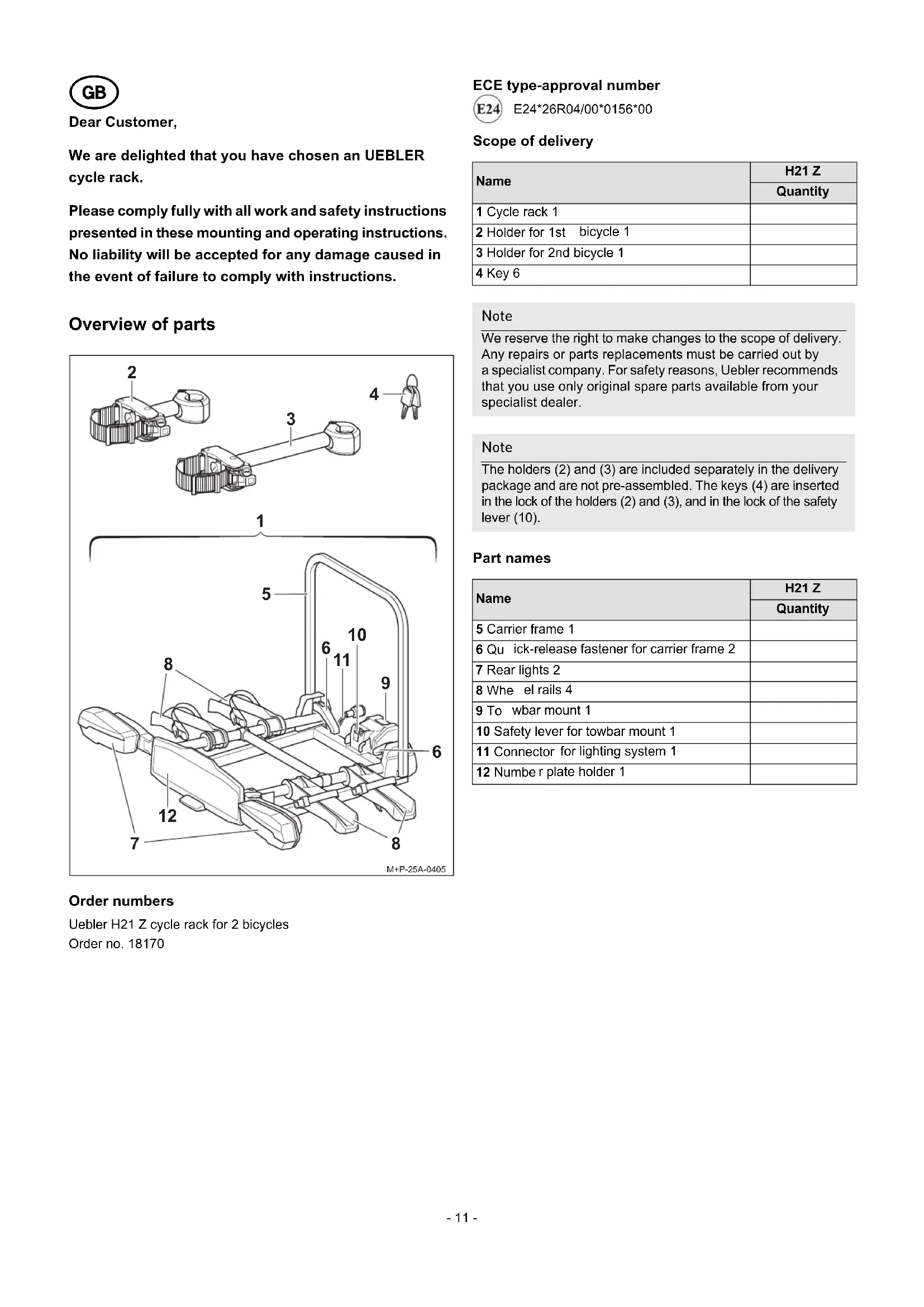
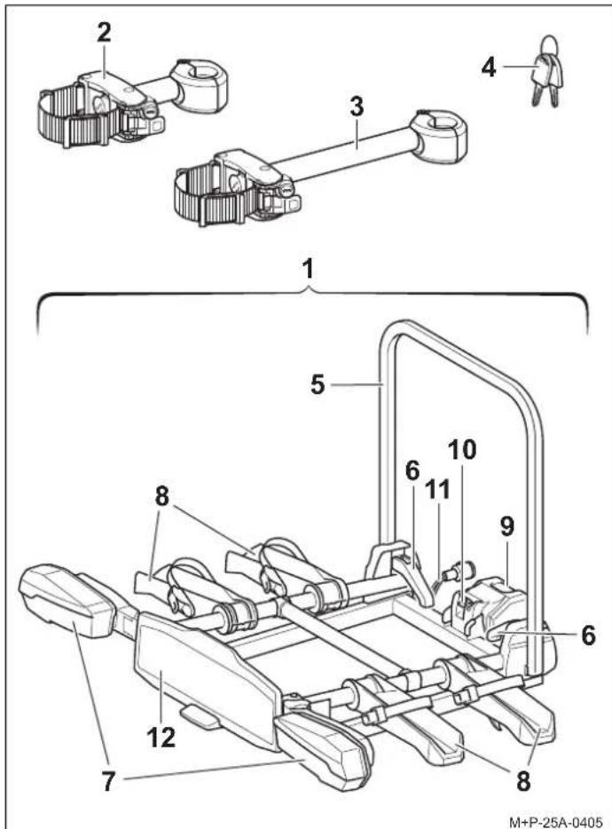
Overview of parts
Order numbers
Uebler H21 Z cycle rack for 2 bicycles
Order no. 18170
ECE type-approval number

E24*26R04/00*0156*00
Scope of delivery
| Name | H21 Z |
| Quantity | |
| 1 Cycle rack 1 | |
| 2 Holder for 1st bicycle 1 | |
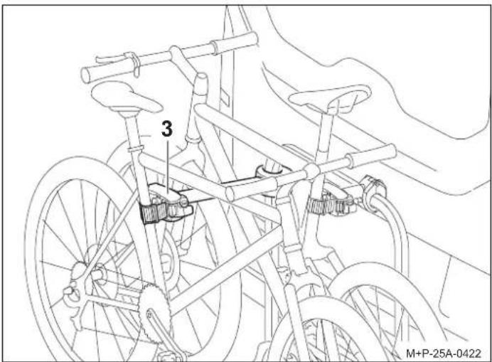
| 3 Holder for 2nd bicycle 1 | |
| 4 Key 6 |
Note
We reserve the right to make changes to the scope of delivery. Any repairs or parts replacements must be carried out by a specialist company. For safety reasons, Uebler recommends that you use only original spare parts available from your specialist dealer.
Note
The holders (2) and (3) are included separately in the delivery package and are not pre-assembled. The keys (4) are inserted in the lock of the holders (2) and (3), and in the lock of the safety lever (10).
Part names
| Name | H21 Z |
| Quantity | |
| 5 Carrier frame 1 | |
| 6 Qu ick-release fastener for carrier frame 2 | |
| 7 Rear lights 2 | |
| 8 Whe el rails 4 | |
| 9 To wbar mount 1 | |
| 10 Safety lever for towbar mount 1 | |
| 11 Connector for lighting system 1 | |
| 12 Number plate holder 1 |
Technical data
| Maximum payload (load capacity) | ||
| Uebler H21 Z: Tongue weighta- tare weight = max. payload | ||
| Tongue weight Tare weight Max. payload | ||
| 165 lbs (75 kg) | Uebler H21 Z = approx. 40 lbs (approx. 18 kg) | 126 lbs (57 kg) |
| ≥ 172 lbs (78 kg) |  | 132 lbs (60 kg) |
a If the values of the towbar and the vehicle differ, the lower value must be taken into account.
| Electrical connection | |
| Power supply 13-pin, 12 V |
| Bicycle weight | |
| Maximum weight per bicycle | 66 lbs (30 kg) |
| Maximum tube diameter of the bicycle frame | |
| Round tube 5 inch (115 mm) | |
| Rectangular tube 5x3 inch | (120x80 mm) |
| Square tube 4x4 inch | (95x95 mm) |
Mounting/unfolding the cycle rack on the vehicle and inserting the number plate

Caution
The towbar and the vehicle must be suitable for attaching a cycle rack:
- Towbar tongue weight (see rating plate on the towbar and vehicle operating instructions)
- Towbar material at least St 52-3 (see rating plate on the towbar)
Failure to comply with the above may cause the cycle rack and mounted bicycles to detach from the vehicle and injure you and others or cause an accident.
The ball head must be cleaned and degreased before mounting.

Caution
When you mount the cycle rack you are altering the dimensions and departure angle of the vehicle. Failure to take this into account could result in injury to you and others and/or damage to property.
Particular care must be taken at entrances and passageways, when driving over bumps, inclines and ramps etc., and when reversing. Use of driver assistance systems, such as parking assistance and rear-view cameras, may be restricted.

Caution
Check that the lighting system is working properly before each journey, otherwise accidents could occur.
Note
The cycle rack must be removed from the vehicle when not in use.
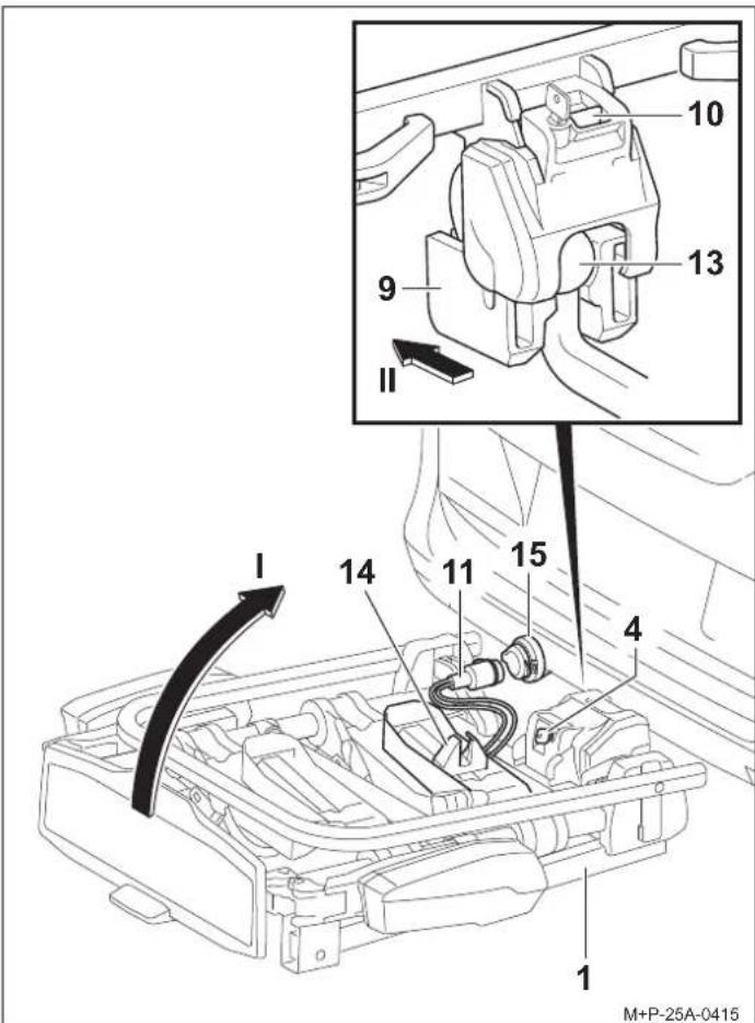
Mounting the cycle rack to the vehicle
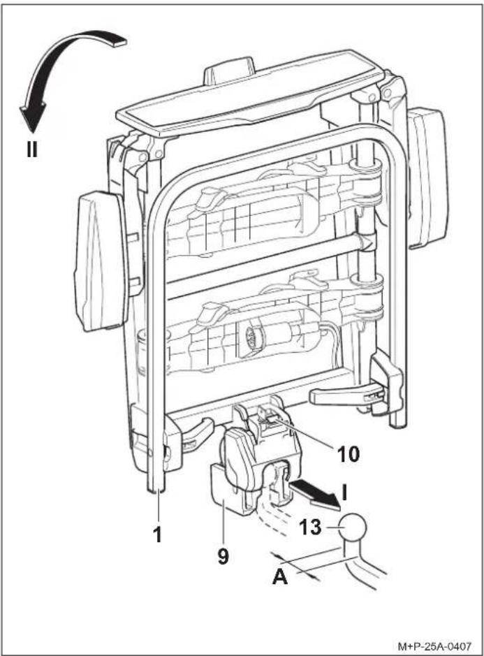
- Press the safety lever (10) so that the mount (9) folds out. If the mount (9) does not fold out automatically, swivel it down manually.
Note
For the H21 Z cycle rack, the coupling neck of the towbar (13) must have a diameter of at least 1 inch (28.5 mm) (A).
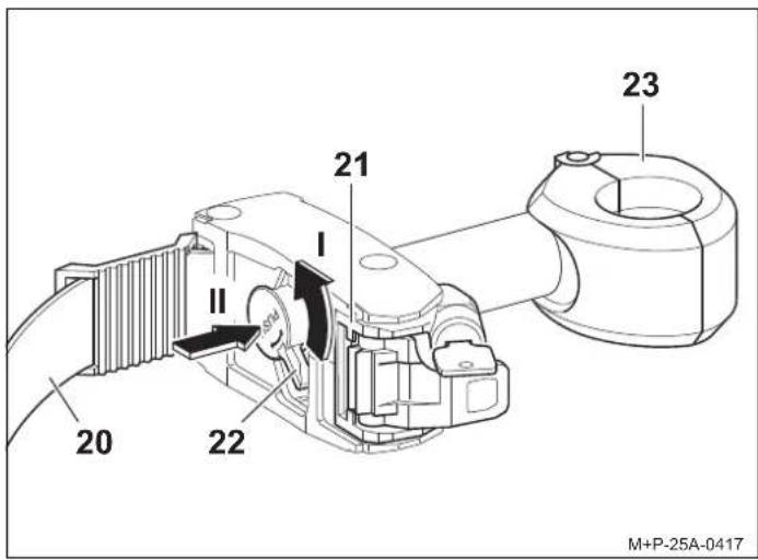
- Hold the cycle rack (1) vertically and slide it onto the ball head (13) with the mount (9) (arrow I).
- Tilt the cycle rack (1) downwards (arrow II) until you hear the safety lever (10) click into place.
The red marking on the safety lever (10) must no longer be visible.
- Check that the cycle rack (1) is parallel to the bumper and roughly level.
Check that the cycle rack (1) is firmly attached by shaking it. If necessary, remove the cycle rack (1) and remount it.
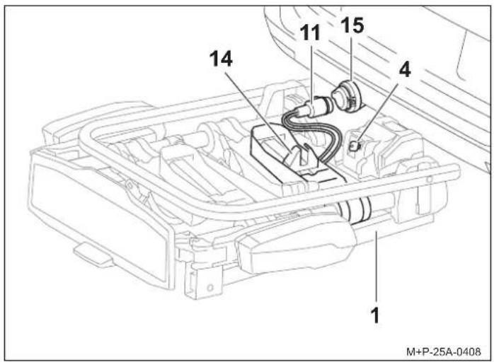
- Lock the cycle rack (1) with the key (4) and remove the key.
- Pull the connector (11) out of the holder (14) and plug it into the socket (15).
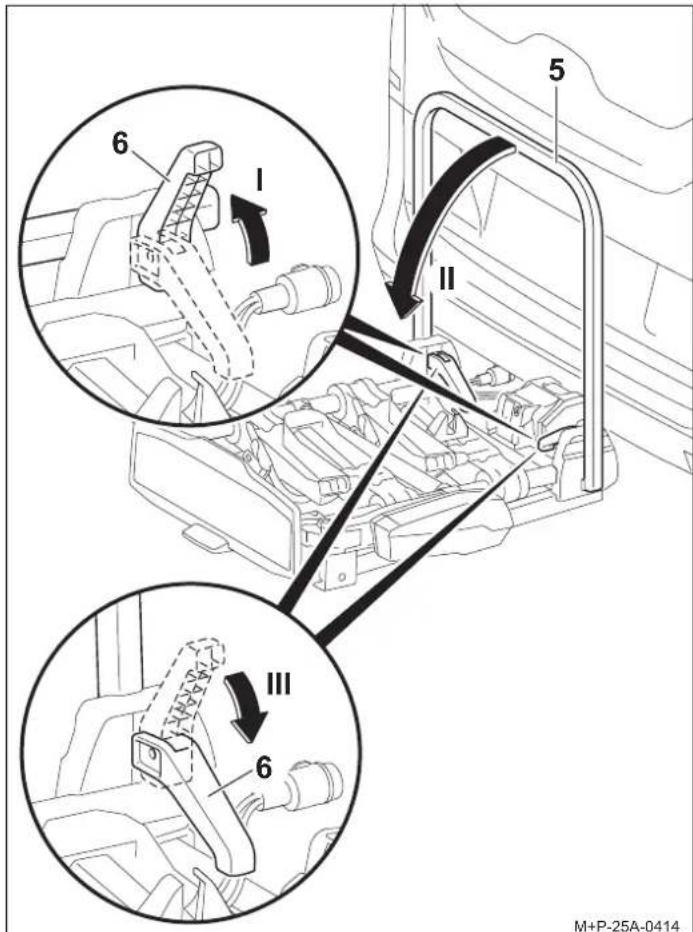
Unfolding the cycle rack
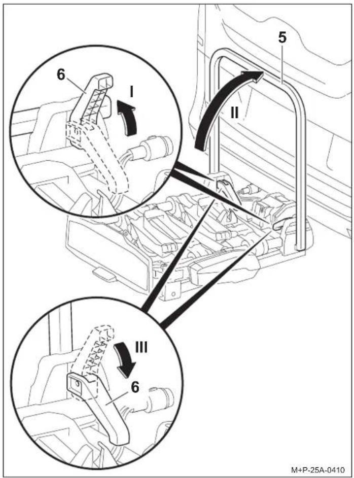
- Open the quick-release fasteners (6) (arrow I) and fold up the carrier frame (5) (arrow II).
- Fully close the quick-release fasteners (6) again (arrow III). The carrier frame (5) is fixed in place.
Note
The quick-release fasteners (6) and the carrier frame (5) must be cleaned with soapy water regularly, or if they become dirty or difficult to move.
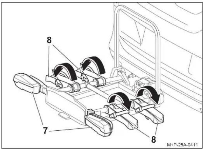
- Fold out the rear lights (7) and click into place.
Note
All wheel rails (8) must be always be folded out, even if only one bicycle is being transported.
-
Fold out the wheel rails (8) and click into place.
-
Check that the lighting system is working.
Inserting the number plate
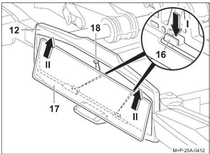
Note
The number plate on the cycle rack must match the vehicle's registration number and be clearly legible.
- Press the holder (16) downwards (arrow I).
- Push the number plate (17) into the number plate holder (12), press upwards and insert fully (arrow II).
- Release the holder (16) and check that the number plate is firmly attached.
Note
To insert taller number plates, press the stopper (18) backwards and push the number plate (17) fully into the number plate holder (12).
Mounting/removing bicycles

Caution
The towbar cycle rack is to be used exclusively for transporting bicycles or the Uebler rear load system.
Only bicycles with a maximum weight of 66 lbs (30 kg) each may be transported on the cycle rack.
The maximum permissible load of the cycle rack, the towbar tongue weight, the permissible total weight of the vehicle and the maximum permissible axle load of the vehicle (see vehicle operating instructions) must not be exceeded under any circumstances.
Failure to comply with the above may cause the cycle rack and mounted bicycles to detach from the vehicle and injure you and others and/or cause an accident.

Caution
The bicycles must be mounted on the cycle rack as evenly as possible and with a low centre of gravity and secured against falling with a holder on the bicycle frame and tensioning straps on the front and rear wheels.
Failure to comply with the above may cause the bicycles and/or loose parts to detach from the vehicle while you are driving, potentially causing an accident involving other road users with associated injury and damage to property.
Before mounting, remove and stow away child seats and all loose parts from the bicycles, such as water bottles, saddlebags, e-bike batteries, etc.

Caution
Depending on the vehicle type, the cycle rack with the bicycles might be positioned too close to the vehicle's exhaust system. The hot exhaust pipe and/or the hot exhaust fumes could damage the cycle rack and/or the bicycles. In this case, the cycle rack is not suitable for use.
When transporting bicycles with carbon fibre parts, contact the manufacturer/dealer to clarify whether these bicycles are suitable for transport on the cycle rack.
Arrangement of bicycles
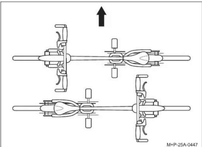
natural_image
Mechanical assembly diagram showing four sequential stages of a mechanical or fluidic component with no visible text or symbolsNote how the bicycles are arranged in an alternating pattern in the direction of travel (arrow).
Note
Mount heavy bicycles close to the vehicle and light bicycles, e.g. children's bicycles, further back on the cycle rack.
Mount the first bicycle with the sprocket facing the vehicle.
Mounting the first bicycle
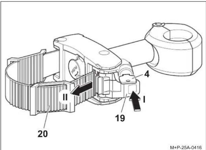
- Unlock the tensioner (19) with the key (4).
- Press the tensioner (19) (arrow I) and pull out the tensioning strap (20) (arrow II).

Note
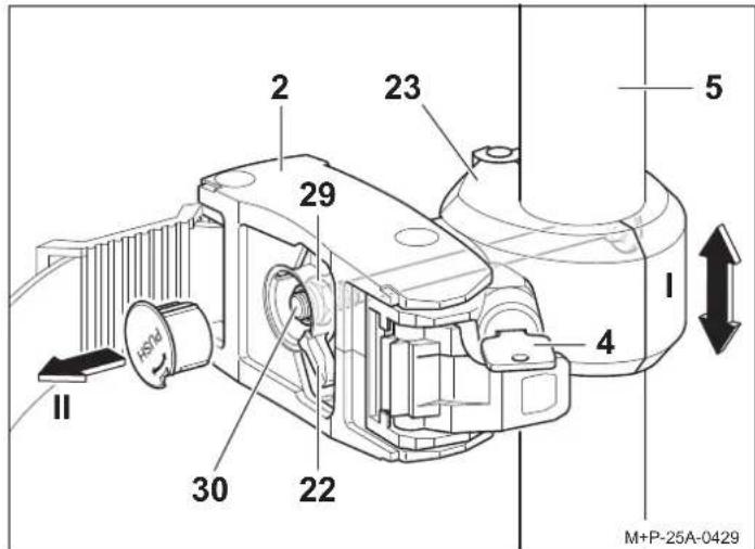
The rotary knob (22) can only be moved when the tensioning strap (20) has been pulled out of the tensioning device (21).
- Turn the rotary knob (22) anti-clockwise (arrow I) and then press and hold (arrow II). The clamp (23) opens.
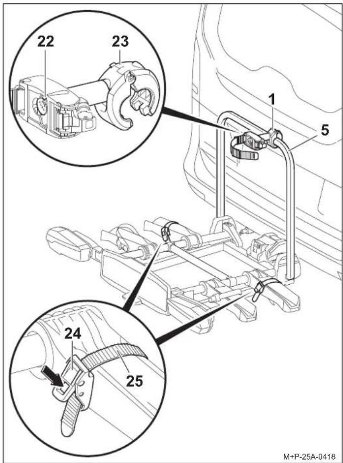
- Position the open clamp (23) around the carrier frame (5) and release the rotary knob (22). The clamp (23) closes.
- Press the tensioner (24) (arrow) and pull out the tensioning strap (25).

Caution
There is a risk of injury if the bicycles slip or tilt. Secure the bicycles against slipping or tilting.
Two people are needed to mount and remove bicycles.

Caution
To prevent damage, only attach the holder (2) to the bicycle frame. Do not clamp other components, e.g. gear and brake cables. Defective holders must be replaced immediately.
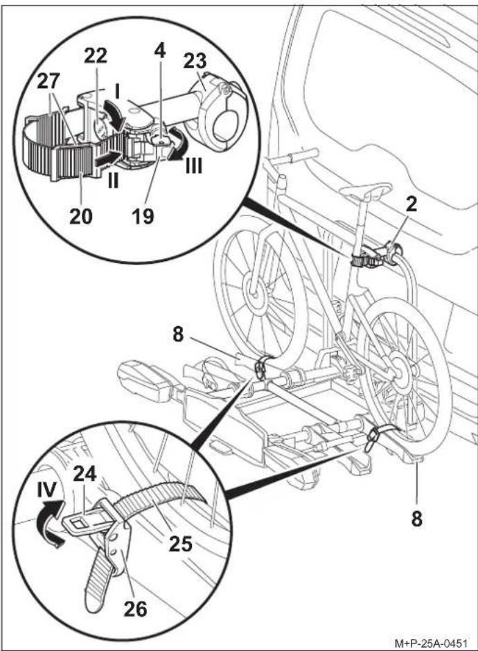
- Place the bicycle on the wheel rails (8) and position the holder (2) at right angles to the bicycle frame.
- Turn the rotary knob (22) clockwise as far as it will go (arrow 1). The clamp (23) is locked in place.
Note
The tensioning strap (20) can only be inserted when the rotary knob (22) is turned fully clockwise.
Note
To protect the bicycle frame, one or two pads (27) can be positioned on the tensioning strap (20) depending on the shape.
- Guide the tensioning strap (20) around the bicycle frame and push it into the tensioning device (21) (arrow II) until you hear it click into place.
- Use the tensioner (19) to tighten the tensioning strap (20) (arrow III).
-
Lock the holder (2) with the key (4) and remove the key.
-
Centre the two tensioning straps (25) between the wheel spokes and insert the straps into the buckles (26) until you hear them click into place.

Caution
Do not overtighten the tensioning straps (25), otherwise the tyres or rims may be damaged.
- Use the tensioner (24) to tighten the tensioning straps (25) (arrow IV).
Mounting the second bicycle

Caution
To prevent damage, only attach the holder (3) to the bicycle frame. Do not clamp other components, e.g. gear and brake cables. Defective holders must be replaced immediately.
The second bicycle is mounted in the same way as the first bicycle. Make sure that the two bicycles are arranged in an alternating pattern.
The second bicycle is attached with the long holder (3).
Removing bicycles

Caution
There is a risk of injury if the bicycles slip or tilt. Secure the bicycles against slipping or tilting. Two people are needed to mount and remove bicycles.
Loosening the holders (2) and (3) and removing the bicycles is done in reverse order.
Adjusting the clamping force
The preload force can be readjusted in the following cases:
- The clamp (23) of the locked holder (2) can be moved on the carrier frame (5) (arrow 1).
• The rotary knob (22) cannot be turned fully clockwise.

Caution
The clamping force may only be adjusted once. If the clamping force is to be adjusted again, the self-locking nut (29) must be replaced.
- Remove the cap from the rotary knob (22), e.g. with a screwdriver (arrow II).
- Attach the holder (2) to the carrier frame (5) and lock it, see page 14.

Caution
Do not completely unscrew the self-locking nut (29). At least one thread must protrude from the threaded rod (30).
- Incre ase clamping force: tighten the nut (29) (AF13) a quarter turn.
Or
Reduce clamping force: loosen the nut (29) (AF13) a quarter turn.
- Check the clamping force of the clamp (23); repeat steps if necessary.
- Replace the cap on the rotary knob (22). The holder for the second bicycle is adjusted in the same way.
Tilting/folding back the cycle rack

Caution
Tilt the cycle rack slowly and make sure that there are no people or objects in the tilting area.
There is a crushing hazard for persons and objects in the tilting area.
Make sure that both hooks click fully into place and lock when folding back the cycle rack, otherwise it could tip over during the journey and injure you or other people and/or cause damage to property.
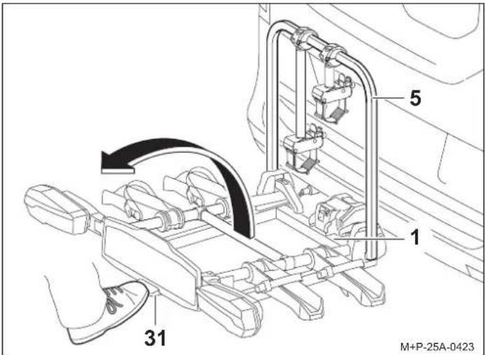
Tilting the cycle rack
The cycle rack can be tilted in order to open the tailgate and to load and unload the vehicle.

Caution
The handlebars of the second bicycle might touch the ground due to the large 90^ tilt angle. This may cause damage to the handlebars. If necessary, remove the bicycle when tilting.
Operate the foot lever (31) and tilt the cycle rack (1) by pulling on the carrier frame (5) or on the bicycle frame if bicycles are already mounted.
Folding back the cycle rack
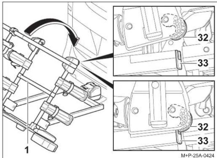
- Fold back the cycle rack (1) until both hooks (32) click into place in the frame (33) and lock.
- Check that the cycle rack (1) is firmly attached by shaking it. If necessary, tilt the cycle rack (1) again and fold it back.
Preparing for travel

Caution
Check that all screw connections and fastenings on the cycle rack and bicycles are firmly attached after each mounting, before each trip and on longer journeys. Retighten if necessary. Failure to comply with the above could lead to the cycle rack and mounted bicycles detaching from the vehicle and potentially injuring you and others and/or causing an accident.
These checks must be repeated at regular intervals depending on road conditions.

Caution
Check that the lighting system is working properly before each journey, otherwise accidents could occur.
Note
The number plate and the lighting system on the cycle rack must not be obscured.
If the cycle rack is not fully loaded, make sure that:
- holders that are not required are removed from the carrier frame and stowed safely in the boot;
- all keys are removed and stowed away; and
- the tensioning straps on all wheel rails are closed.
Folding up/removing the cycle rack from the vehicle
Folding up the cycle rack
- The wheel rails and rear lights are folded in reverse order.
- Open the quick-release fasteners (6) (arrow I) and fold down the carrier frame (5) (arrow II).
- Fully close the quick-release fasteners (6) again (arrow III). The carrier frame (5) is fixed in place.
Note
The quick-release fasteners (6) and the carrier frame (5) must be cleaned with soapy water regularly, or if they become dirty or difficult to move.
Removing the cycle rack from the vehicle
- Unplug the connector (11) from the socket (15) and insert it into the holder (14).
- Unlock the cycle rack (1) with the key (4).
- Press the safety lever (10) and swivel the cycle rack (1) vertically upwards (arrow I).
- Pull the cycle rack (1) backwards from the ball head (13) (arrow II).
- Place the cycle rack (1) with the mount (9) on the ground. The mount (9) closes.
Bulb replacement

Caution
To change the bulbs, the vehicle ignition must be switched off and the connector for the lighting system must be disconnected from the socket for the towbar electrics. Failure to comply with the above may result in a short circuit or damage to property. If in doubt, use a specialist company to replace bulbs.
Aids
- Torx T15 (inside)
Note
The bulb replacement procedure is described and illustrated using the left-hand rear light of the cycle rack. Proceed in the same way to replace the right-hand rear light.
Note
When ordering a new bulb, please specify the name of the bulb you need.
| Name | Spare part no. |
| 34 Indicator ^a BL PY21W 12V yellow | E1687 |
| 35 Number plate light ^a BL C5W 12V (35 mm long) white | E1687 |
| 36 Rear fog light ^a for left rear lightBL PR21W 12V red | E1687 |
| 36 Reversing light ^a for right rear lightBL P21W 12V white | E1687 |
| 37 Brake/rear light ^a BL P21/5W 12V white | E1687 |
a The bulb is commercially available.
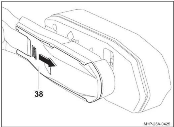
- Press the cover (38) on the ribbing, slide outwards and remove.
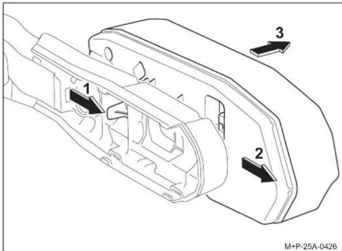
- Release the lock (arrow 1) and slide the light (arrow 2) out of the holder and remove it (arrow 3).

Caution
When removing the rear light, do not place the connection cable under high mechanical tension. Failure to comply may result in damage to property.
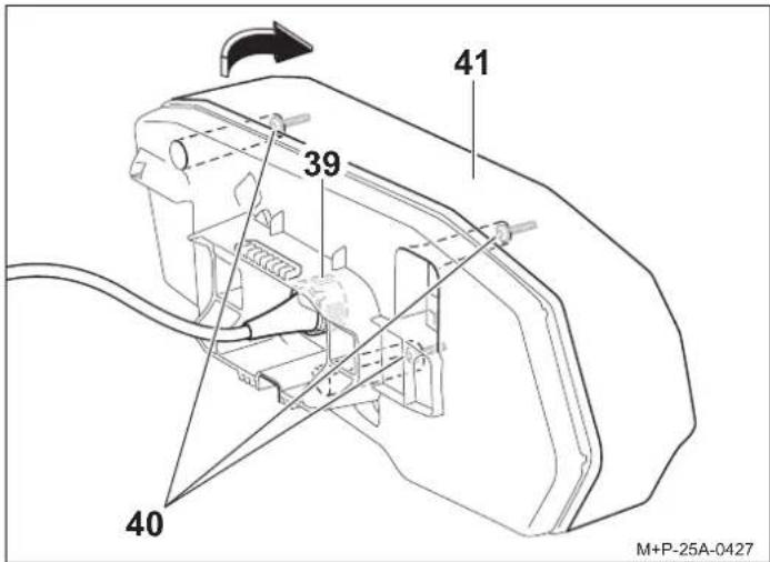
- Turn the connector (39) 90^ in an anti-clockwise direction and remove it.
- Unscrew the screws (40) and remove the diffusing lens (41) in the direction of the arrow.
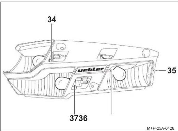
- Gently press the defective bulb into the socket (34), (36) or (37), turn it 90° in an anti-clockwise direction and remove it.
- Remove the defective bulb from the socket (35).
Note
Only touch new bulbs with a clean cloth and insert them into the socket (34), (35), (36) or (37).
- Press the new bulb into the socket (34), (36) or (37) and turn 90° in a clockwise direction. See table for the required bulbs.
- Press the new bulb into the socket (35). See table for the required bulbs.
Assembly is in the reverse order to removal.
General safety instructions
The driver is responsible for ensuring that their vision and hearing are not impaired by the cycle rack, the bicycles or the condition of the vehicle. The driver must ensure that the vehicle, the cycle rack and bicycles comply with regulations and that road safety is not impaired.
Prescribed lighting and lighting equipment must also be present and operational, including during the day.
These mounting and operating instructions include the general approval of the towbar cycle rack and must be kept in the vehicle at all times.
Please follow the relevant statutory provisions for the use of cycle racks in the country of use.

Caution
Please comply fully with all work and safety instructions presented in these mounting and operating instructions.
The towbar cycle rack is to be used exclusively for transporting bicycles or for the Uebler rear box system. The cycle rack is not suitable for off-road use.
Check that all screw connections and fastenings on the cycle rack and bicycles are firmly attached after each mounting, before each trip and on longer journeys. Retighten if necessary. These checks must be repeated at regular intervals depending on road conditions.
When driving, the driver should check the cycle rack and bicycles for any displacement by looking in the rear-view mirror.
If anything has changed, the driver should continue driving at reduced speed to the next safe stopping point and retighten the screw connections and fastenings on the cycle rack and/or bicycles.
Failure to comply with the above may cause the cycle rack and mounted bicycles to detach from the vehicle and injure you and others and/or cause an accident.

Caution
Moving parts, e.g. the quick-release fastener screws, must be cleaned and lubricated at regular intervals to prevent them from seizing.
Do not use lubricant on any other screw connections. The screw connections could easily loosen and the cycle rack and mounted bicycles could detach from the vehicle and injure you and others and/or cause an accident.

Caution
If the mounted bicycles protrude more than 16 inch (40 cm) beyond the outermost edge of the illuminated surface of the cycle rack's marker or tail lights, they must be marked with a white light to the front and a red light to the rear, positioned laterally no more than 16 inch (40 cm) from the edge of the bicycle and no more than 59 inch (150 cm) above the carriageway.
When transporting the bicycles, separately mark the wheels that protrude to the side.
When driving at night, cover the rear lights and wheel reflectors to prevent confusion with the vehicle's rear lights and to avoid hindering or misleading other road users.
Failure to comply with the above may cause an accident.

Caution
Check that the lighting system is working before you start your trip. When the rear fog light on the cycle rack is switched on, the rear fog light on the vehicle must be switched off, i.e. they must not light up at the same time.
For vehicle models whose type approval was first granted after 1 October 1998, neither the fitted cycle rack nor the mounted bicycles may obscure the vehicle's third brake light. The vehicle's third brake light must be visible: to the right and left in relation to the vehicle's longitudinal axis – at a horizontal angle of 10^ , upwards in relation to the edge of the light – at a vertical angle of 10^ and downwards – in relation to the lower edge of the light – at a vertical angle of 5^ .
If these values are not complied with, a "third" replacement brake light must be fitted.
Failure to comply with the above could cause an accident.

Caution
Mounting the cycle rack and bicycles changes the driving and braking characteristics as well as the vehicle's susceptibility to crosswinds. The maximum speed of 81 mph (130 km/h) must not be exceeded.
Do not cover the bicycles with tarpaulins, protective covers or similar, as this significantly affects the area exposed to the wind and the driving characteristics.
Heavy loads in the boot should be pushed as far forwards as possible to prevent excessive rear loading.
Always adapt your driving style to the road, traffic and weather conditions, and drive with particular care when the cycle rack is loaded.
Failure to comply with the above may cause the cycle rack and mounted bicycles to detach from the vehicle and injure you and others and/or cause an accident.

Caution
If the vehicle is equipped with an electric tailgate, ensure that there is sufficient clearance when the cycle rack is mounted. If possible, the electric tailgate should be deactivated and operated manually.
Remove the cycle rack before using a car wash. Otherwise the cycle rack, the vehicle and/or the car wash could be damaged.
Note on disposal
Dispose of components, accessories and packaging for environmentally friendly recycling. Do not dispose of the bulb kit in your household or non-recyclable waste.
In accordance with European Directive 2012/19/EU and the Electrical and Electronic Equipment Act (ElektroG), electrical appliances that are no longer fit for use must be collected separately and recycled in an environmentally friendly manner.
Separate the bulb kit from the carrier and take the components that are no longer usable to a suitable collection point.
Ask your specialist dealer for advice.


Cher client,
natural_image
Mechanical assembly diagram showing four sequential stages of a mechanical or fluidic component with no visible text or symbolsRemarque

Attention
natural_image
Mechanical assembly diagram showing four sequential stages of a mechanical or fluidic component with no visible text or symbolsNota

Precaución
natural_image
Mechanical assembly diagram showing four sequential stages of a mechanical or fluidic component with no visible text or symbolsOpmerking

Let op
Opmerking over recycling
natural_image
Mechanical assembly diagram showing four sequential stages of a mechanical or fluidic component with no visible text or symbolsInformacja

Uwaga
Montar/desmontar as bicicletas

Cuidado
natural_image
Mechanical assembly diagram showing four sequential stages of a mechanical or fluidic component with no visible text or symbols- Desbloquear o tensor (19) com a chave (4).
- Pressionar o tensor (19) (seta I) e puxar a correia tensora (20) (seta II).
Nota

Cuidado
Desmontar as bicicletas

Cuidado
natural_image
Mechanical assembly diagram showing four sequential stages of a mechanical or fluidic component with no visible text or symbols
Upozornění
- Åbn hurtigudløserne (6) (pil I), og klap holderrammen (5) op (pil II).
- Luk hurtigudløserne (6) helt igen (pil III). Holderrammen (5) er fastgjort.
Bemærk!
natural_image
Mechanical assembly diagram showing four sequential stages of a mechanical or fluidic component with no visible text or symbolsBemærk!

Forsigtig!
natural_image
Mechanical assembly diagram showing four sequential stages of a mechanical or fluidic component with no visible text or symbolsÉrtesítés

Vigyázat
natural_image
Mechanical assembly diagram showing four sequential stages of a mechanical or fluidic component with no visible text or symbolsNota

Attenzione
- Mounting and operating instructions
- Hinweis
- Vorsicht
- Order numbers
- ECE type-approval number
- Note
- Mounting/unfolding the cycle rack on the vehicle and inserting the number plate
- Caution
- Mounting/removing bicycles
- Arrangement of bicycles
- Mounting the first bicycle
- Removing bicycles
- Tilting/folding back the cycle rack
- Tilting the cycle rack
- Folding back the cycle rack
- Preparing for travel
- Folding up/removing the cycle rack from the vehicle
- Bulb replacement
- Aids
- General safety instructions
- Note on disposal
- Remarque
- Attention
- Nota
- Precaución
- Opmerking
- Let op
- Opmerking over recycling
- Informacja
- Uwaga
- Montar/desmontar as bicicletas
- Cuidado
- Desmontar as bicicletas
- Upozornění
- Bemærk!
- Forsigtig!
- Értesítés
- Vigyázat
- Attenzione
Brand : Uebler
Model : H21 Z
Category : Bike rack