ThunderWash 600 UV - Lighting Cameo - Free user manual and instructions
Find the device manual for free ThunderWash 600 UV Cameo in PDF.
Download the instructions for your Lighting in PDF format for free! Find your manual ThunderWash 600 UV - Cameo and take your electronic device back in hand. On this page are published all the documents necessary for the use of your device. ThunderWash 600 UV by Cameo.
USER MANUAL ThunderWash 600 UV Cameo
INSTALLATION AND MOUNTING 7
DMX TECHNOLOGY 8 TECHNICAL DATA 9
MANUFACTURER’S DECLARATIONS 9
CONTROLLO DMX 453 DMX DEUTSCHFRANCAIS ESPAÑOL ENGLISH ITALIANO POLSKI ENGLISH YOU‘VE MADE THE RIGHT CHOICE! We have designed this product to operate reliably over many years. Please read this User‘s Manual carefully, so that you can begin making optimum use of your Cameo Light product quickly. Learn more about Cameo Light on our website WWW.CAMEOLIGHT.COM. PREVENTIVE MEASURES
1. Please read these instructions carefully.
2. Keep all information and instructions in a safe place.
3. Follow the instructions.
4. Observe all safety warnings. Never remove safety warnings or other information from the equipment.
5. Use the equipment only in the intended manner and for the intended purpose.
6. Use only sufficiently stable and compatible stands and/or mounts (for fixed installations). Make certain that wall mounts are properly installed and secured. Make certain that the equipment is installed securely and cannot fall down.
7. During installation, observ e the applicable safety regulations for your country.
8. Never install and operate the equipment near radiators, heat registers, ovens or other sources of heat. Make certain that the equipment is always installed so that is cooled sufficiently and cannot overheat.
9. Never place sources of ignition, e.g., burning candles, on the equipment.
10. Ventilation slits must not be blocked.
11. This appliance is designed exclusively for indoor use, do not use this equipment in the immediate vicinity of water (does not apply to special outdoor equipment - in this case, observe the special instructions noted below). Do not expose this equipment to flammable materials, fluids or gases. 12. Make certain that dripping or splashed water cannot enter the equipment. Do not place containers filled with liquids, such as vases or drinking vessels, on the equipment.
13. Make certain that objects cannot fall into the device.
14. Use this equipment only with the accessories recommended and intended by the manufacturer.
15. Do not open or modify this equipment.
16. After connecting the equipment, check all cables in order to prevent damage or accidents, e.g., due to tripping hazards. 17. During transport, make certain that the equipment cannot fall down and possibly cause property damage and personal injuries. 18. If your equipment is no longer functioning properly, if fluids or objects have gotten inside the equipment or if it has been damaged in anot her way, switch it off immediately and unplug it from the mains outlet (if it is a powered device). This equipment may only be repaired by authorized, qualified personnel.
19. Clean the equipment using a dry cloth.
20. Comply with all applicable disposal laws in your country. During disposal of packaging, please separate plastic and paper/cardboard.
21. Plastic bags must be kept out of reach of children.
FOR EQUIPMENT THAT CONNECTS TO THE POWER MAINS: 22. CAUTION: If the power cord of the device is equipped with an earthing contact, then it must be connected to an outlet with a protective ground. Never deactivate the protective ground of a power cord. 23. If the equipment has been exposed to strong fluctuations in temperature (for example, after transport), do not switch it on immediately. Moisture and condensation could damage the equipment. Do not switch on the equipment until it has reached room temperature. 24. Before connecting the equipment to the power outlet, first verify that the mains voltage and frequency match the values specified on the equipment. If the equipment has a voltage selection switch, connect the equipment to the power outlet only if the equipment values and the mains power values match. If the included power cord or power adapter does not fit in your wall outlet, contact your electrician. 25. Do not step on the power cord. Make certain that the power cable does not become kinked, especially at the mains outlet and/or power adapter and the equipment connector. 26. When connecting the equipment, make certain that the power cord or power adapter is always freely accessible. Always disconnect the equipment from the power supply if the equipment is not in use or if you want to clean the equipment. Always unplug the power cord and power adapter from the power outlet at the plug or adapter and not by pulling on the cord. Never touch the power cord and power adapter with wet hands. 27. Whenever possible, avoid switching the equipment on and off in quick succession because otherwise this can shorten the useful life of the equipment. 28. IMPORTANT INFORMATION: Replace fuses only with fuses of the same type and rating. If a fuse blows repeatedly, please contact an authorised service centre. 29. To disconnect the equipment from the power mains completely, unplug the power cord or power adapter from the power outlet. 30. If your device is equipped with a Volex power connector, the mating Volex equipment connector must be unlocked before it can be re- moved. However, this also means that the equipment can slide and fall down if the power cable is pulled, which can lead to personal injuries and/or other damage. For this reason, always be careful when laying cables. 31. Unplug the power cord and power adapter from the power outlet if there is a risk of a lightning strike or before extended periods of disuse.
32. The device must only be installed in a voltage-free condition (disconnect the mains plug from the mains).
33. Dust and other debris inside the unit may cause damage. The unit should be regularly serviced or cleaned (no guarantee) depending on ambient conditions (dust etc., nicotine, fog) by qualified personnel to prevent overheating and malfunction.
34. Please keep a distance of at least 0.5 m to any combustible materials.
35. Power cables to power multiple devices must have a cross-section of at least 1.5 mm². Within the EU, the cables must correspond to H05VV-F, or similar. Suitable cables are offered by Adam Hall. With these cables, you can connect multiple devices via the power OUT connection to the power IN connection of an additional device. Make sure that the total current consumption of all connected devices does not exceed the specified value on all connected devices (label on the device). Make sure to keep power cable connections as short as possible.4 DMX ITALIANO POLSKI ESPAÑOL FRANCAIS DEUTSCHENGLISH CAUTION: To reduce the risk of electric shock, do not remove cover (or back). There are no user serviceable parts inside. Maintenance and repairs should be exclusively carried out by qualified service personnel. The warning triangle with lightning symbol indicates dangerous uninsulated voltage inside the unit, which may cause an electrical shock. The warning triangle with exclamation mark indicates important operating and maintenance instructions. 2) Warning! This symbol indicates a hot surface. Certain parts of the housing can become hot during operation. After use, wait for a cool-down period of at least 10 minutes before handling or transporting the device. Warning! This device is designed for use below 2000 metres in altitude. Warning! This product is not intended for use in tropical climates. Caution! Intense LED light source! Risk of eye damage. Do not look into the light source. CAUTION! IMPORTANT INFORMATION ABOUT LIGHTING PRODUCTS! 1. The product has been developed for professional use in the field of event technology and is not suitable as household lighting.
2. Do not stare, even temporarily, directly into the light beam.
3. Do not look at the beam directly with optical instruments such as magnifiers.
4. Stroboscope effects may cause epileptic seizures in sensitive people! People with epilepsy should definitely avoid places where strobes are used. INTRODUCTION
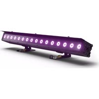
CLTW600UV CONTROL FUNCTIONS 1-channel 1, 1-channel 2, 2-channel, 4-channel DMX control Master/Slave operation Standalone operation FEATURES 648 x 0.2W UV LEDs. DMX-512 control. Master/Slave operation. Standalone operation. Sound control via built-in microphone. Universal mounting options. Operating voltage 100–240 V AC/50–60Hz. Power consumption 160W.5 DMX DEUTSCHFRANCAIS ESPAÑOL ENGLISH ITALIANO POLSKI
POWER IN IEC mains socket with built-in fuse holder. A suitable IEC power cable is included. IMPORTANT: Replace the fuse only with a fuse of the same type and value. In the event of repeated fuse failure, please contact an author- ised service centre.
DMX IN Male 3-pin XLR socket for connection to a DMX control device (e.g. DMX console).
DMX OUT Female 3-pin XLR socket for sending the DMX control signal.
LED DISPLAY The four-digit LED display shows the operating mode and other system information.
CONTROL BUTTONS MODE: Select the different operating modes and the menu item DMX start address. ENTER: Press ENTER to make value changes in the various menu items. Confirm value changes by pressing ENTER. UP and DOWN: Use these buttons to alter the value of a menu item as required, e.g. DMX address.
- A short time after the light has been connected correctly to the mains, the spotlight is ready for operation and starts in the previously enabled mode.
- The display turns off about 15 seconds after the last entry via the buttons. A small red dot appears at the bottom of the display at the same time. In DMX mode, the dot begins to flash when a control signal is present. It stops flashing if the control signal is interrupted.
Press the MODE button until one of the available DMX modes is shown in the display and press ENTER. Use the UP/DOWN buttons to select the desired DMX mode and confirm the entry with ENTER (1-channel 1, 1-channel 2, 2-channel, 4-channel). Tables with the channel assignment of the different DMX modes can be found in these instructions under DMX CONTROL.
Press the MODE button until the currently activated DMX start address is displayed (A001–A512) and press ENTER (the characters in the display will flash). The DMX start address can now be adjusted as desired with the UP and DOWN buttons. Confirm with ENTER. Synchro- nous control of several lamps of the same model with a DMX controller (e.g. DMX console) can be achieved by configuring the lights with the same DMX mode and the same DMX start address and connecting them via DMX cables.
ENTER UP/DOWN ENTER MANUAL MODE The manual mode allows you to adjust the brightness of the UV LEDs and activate a strobe effect. Press the MODE button repeatedly until “C000” appears in the display. Now press ENTER then use the UP and DOWN buttons to select either the menu item “C1xx” for brightness, or the menu item “CFxx” to configure the strobe effect. When you have selected a menu item, press ENTER again and you can now use the UP and DOWN buttons to set the value as required for brightness or for the stroboscopic effect (see table). Confirm your entry with ENTER. Manual mode C100 Blackout C101 minimum brightness C199 maximum brightness CF00 Strobe disabled CF01 Strobe approx. 1 Hz CF99 Strobe approx. 30 Hz FADING MODE Gentle fading the UV LEDs in and out from blackout to maximum brightness and back to blackout at an adjustable speed. A strobe effect can also be activated. Press the MODE button repeatedly until “FA00” appears in the display. Press ENTER then use the UP and DOWN buttons to select either the menu item “FAxx” for the fade speed, or the menu item “FFxx” to configure the strobe effect. When you have selected a menu item, press ENTER again to be able to use the UP and DOWN buttons to set the value as required for the fading speed or for the stroboscopic effect (see table). Confirm your entry with ENTER. Fading mode FA00 minimum fade speed FA99 maximum fade speed FF00 Strobe disabled FF01 Strobe approx. 1 Hz FF99 Strobe approx. 30 Hz AUTO MODE The Auto mode combines the fading mode with a strobe effect, whereby this is activated and deactivated at regular intervals. Press the MODE button until “AUTO” is shown in the display, then press ENTER to use the UP and DOWN buttons to set the effect speed as required. Confirm with ENTER. Auto mode AU00 minimum effect speed AU99 maximum effect speed SLAVE MODE Press the MODE button repeatedly until “SLAV” appears in the display. Connect the slave and the master units (same model) with a DMX cable and enable one of the standalone modes on the master unit (manual mode, auto, fading mode, sound-control). Now the slave unit will follow the master unit.7 DMX DEUTSCHFRANCAIS ESPAÑOL ENGLISH ITALIANO POLSKI
INSTALLATION AND MOUNTING
Thanks to its universal double bracket, the lamp can be positioned in a suitable location on a level surface. Installation on a traverse is possible with a suitable traverse clamp, which is attached to the mounting bracket (A). Traverse clamps are available as an option. Ensure firm connections and secure the spotlight to the securing lug (B) with a suitable safety cable. Important: Overhead mounting requires extensive experience, including the calculation of the load limit values of the installation material and regular safety inspection of all installation materials and spotlights. If you do not have these qualifications, do not attempt to perform an installation yourself. Refer instead to a qualified professional.
SOUND CONTROL Press the MODE button repeatedly until “SOUN” appears in the display. The LED washlight will now be controlled via the built-in microphone and will follow the rhythm of the music (bass signals). Press the ENTER key and use the UP and DOWN buttons to set the sensitivity with which the washlight reacts to acoustic impulses. Confirm with ENTER. Music control SO00 minimum sensitivity SO99 maximum sensitivity8 DMX ITALIANO POLSKI ESPAÑOL FRANCAIS DEUTSCHENGLISH DMX TECHNOLOGY DMX-512 DMX (Digital Multiplex) is the designation for a universal transmission protocol for communications between corresponding devices and controllers. A DMX controller sends DMX data to the connected DMX device(s). The DMX data is always transmitted as a serial data stream that is forwarded from one connected device to the next via the "DMX IN" and "DMX OUT" connectors (XLR plug-type connectors) that are found on every DMX-capable device, provided the maximum number of devices does not exceed 32 units. The last device in the chain needs to be equipped with a terminator (terminating resistor). DMX CONNECTION DMX is the common "language" via which a very wide range of types and models of equipment from various manufacturers can be connected with one another and controlled via a central controller, provided that all of the devices and the controller are DMX compatible. For optimum data transmission, it is necessary to keep the connecting cables between the individual devices as short as possible. The order in which the devices are integrated in the DMX network has no influence on the addresses. Thus the device with the DMX address 1 can be located at any position in the (serial) DMX chain: at the beginning, at the end or somewhere in the middle. If the DMX address 1 is assigned to a device, the controller "knows" that it should send all data allocated to address 1 to this device regardless of its position in the DMX network.
SERIAL CONNECTION OF MULTIPLE LIGHTS
1. Connect the male XLR connector (3-pin or 5-pin) of the DMX cable to the DMX output (female XLR socket) of the first DMX device (e.g. DMX-Controller). 2. Connect the female 3-pin XLR connector of the DMX cable connected to the first projector to the DMX input (male 3-pin socket) of the next DMX device. In the same way, connect the DMX output of this device to the DMX input of the next device and repeat until all devices have been connected. Please note that as a rule, DMX devices are connected in series and connections cannot be shared without active splitters. The maximum number of DMX devices in a DMX chain should not exceed 32 units. The Adam Hall 3 STAR, 4 STAR, and 5 STAR product ranges include an extensive selection of suitable cables. DMX CABLES When fabricating your own cables, always observe the illustrations on this page. Never connect the shielding of the cable to the ground contact of the plug, and always make certain that the shielding does not come into contact with the housing of the XLR plug. If the shielding is connected to the ground, this can lead to short-circuiting and system malfunctions. Pin Assignment DMX cable with 3-pin XLR connectors: DMX cable with 5-pin XLR connectors (pin 4 and 5 are not used): Shield
Shield DMX TERMINATORS (TERMINATING RESISTORS) To prevent system errors, the last device in a DMX chain needs to be equipped with a terminating resistor (120 ohm, 1/4 Watt). 3-pin XLR connector with a terminating resistor: K3DMXT3 5-pin XLR connector with a terminating resistor: K3DMXT5 Pin Assignment 3-pin XLR connector: 5-pin XLR connector:
DMX ADAPTER The combination of DMX devices with 3-pin connectors and DMX devices with 5-pin connectors in a DMX chain is possible with suitable adapters. Pin Assignment DMX Adapter 5-pin XLR male to 3-pin XLR female: K3DGF0020 Pins 4 and 5 are not used. Pin Assignment DMX Adapter 3-pin XLR male to 5-pin XLR female: K3DHM0020 Pins 4 and 5 are not used.9 DMX DEUTSCHFRANCAIS ESPAÑOL ENGLISH ITALIANO POLSKI TECHNICAL DATA Product number: CLTW600UV Product type: LED light Type: Washlight/strobe Colour spectrum: UV Number of LEDs: 648 LED type: 0.2 W Beam angle: 75° DMX input: 3-pin male XLR DMX output: 3-pin female XLR DMX modes: 1-channel 1 1-channel 2 2-channel 4-channel DMX functions: dimmer, strobe, music control Standalone modes: manual mode, fading mode, strobe, slave mode, auto mode, music control Operating controls: Enter, Mode, Value Up, Value Down Display: 4-digit LED display Operating voltage: 100–240 V AC/50–60 Hz Power consumption: 160 W Power connection: IEC input Fuse: F3AL/250 V Operating temperature: 0°C to 40°C Relative air humidity: < 85%, non-condensing Housing material: Metal Housing colour: black Housing cooling: Temperature-controlled fan Dimensions (W x H x D, without bracket): 335 x 197 x 93 mm Weight: 4.1 kg Additional features: Power cable and stand/mounting bracket included