
RT001G - Milling machine MAKITA - Free user manual and instructions
Find the device manual for free RT001G MAKITA in PDF.

| Product type | Cordless router |
| Brand | Makita |
| Model | RT001G |
| Collet capacity | 6 mm, 8 mm or 1/4" |
| No load speed | 10,000 to 31,000 min⁻¹ |
| Rated voltage | 36 V - 40 V DC max. |
| Overall height (with BL4025) | 245 mm |
| Net weight | 2.2 to 2.5 kg (depending on battery) |
| Sound pressure level (LpA) | 84 dB(A) |
| Sound power level (LWA) | 92 dB(A) |
| Vibration (no load) | 2.5 m/s² or less |
| Compatible batteries | BL4020, BL4025, BL4040 |
| Compatible chargers | DC40RA, DC40RB, DC40RC |
| Electronic functions | Constant speed control, soft start, soft brake |
| LED light | Yes, with indicator |
| Wireless activation | Yes (with optional connector) |
| Main applications | Flush trimming and profiling of wood, plastic and similar materials |
| Included accessories | Straight cut guide, wrenches, collet cone, dust nozzle |
| Maintenance | Clean with a dry cloth, do not use solvents |
| Warranty | Consult Makita after-sales service |
Frequently Asked Questions - RT001G MAKITA
User questions about RT001G MAKITA
0 question about this device. Answer the ones you know or ask your own.
Ask a new question about this device
Download the instructions for your Milling machine in PDF format for free! Find your manual RT001G - MAKITA and take your electronic device back in hand. On this page are published all the documents necessary for the use of your device. RT001G by MAKITA.
USER MANUAL RT001G MAKITA
natural_image
Line drawing of a mechanical device with no visible text or symbols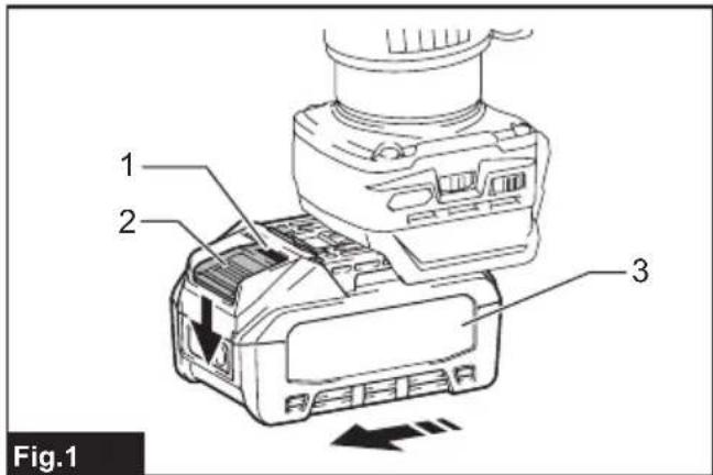
natural_image
Technical line drawing of a mechanical component with labeled parts (no text or symbols beyond label)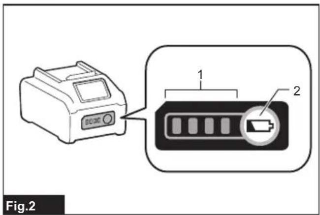
natural_image
Technical diagram of a mechanical device with a magnified inset showing internal components (no text or symbols)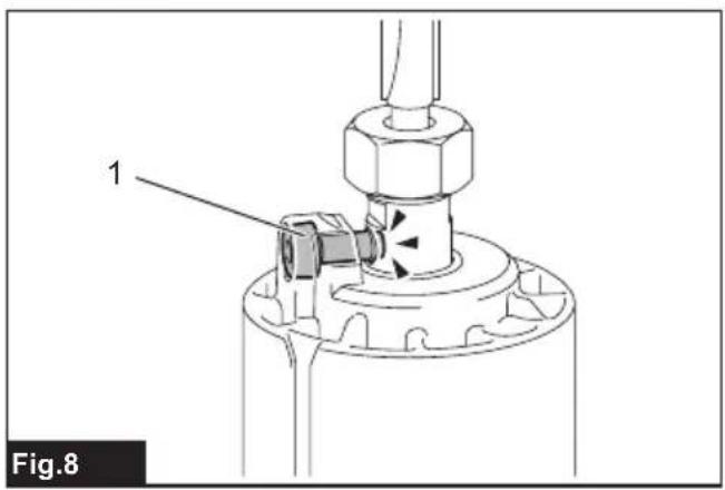
natural_image
Technical diagram of a mechanical assembly with labeled component 1 (no text or symbols beyond label)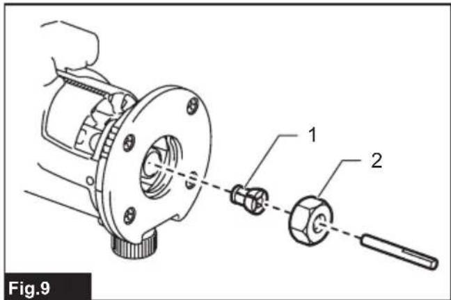
natural_image
Technical diagram of a mechanical device with a cylindrical component and a base, showing internal components and motion arrows (no text or symbols)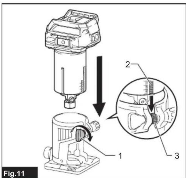

natural_image
Line drawing of a mechanical device connected to a coiled cable, labeled Fig.13 (no text or symbols on the diagram itself)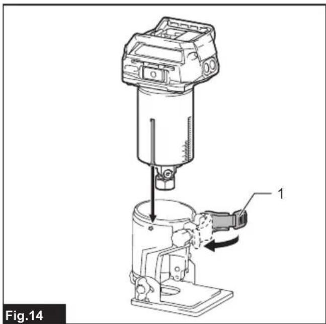
natural_image
Technical illustration of a mechanical device with labeled component 1, showing internal components and motion arrows (no text or symbols beyond label)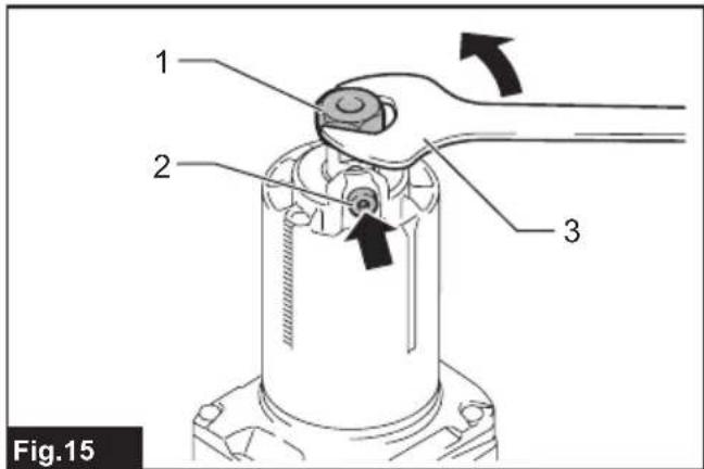
natural_image
Mechanical assembly diagram showing a component with pins and mounting holes (no text or symbols)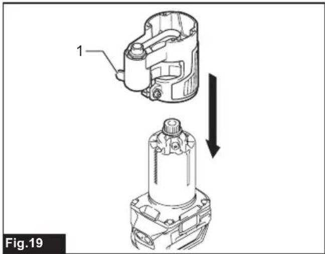
natural_image
Technical illustration of a mechanical component with two views, one showing internal structure and the other showing a cylindrical assembly (no text or symbols)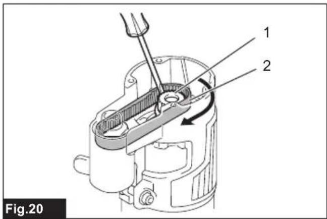
natural_image
Technical diagram of a mechanical device with labeled component 1, showing internal structure and motion arrows (no text or symbols beyond label)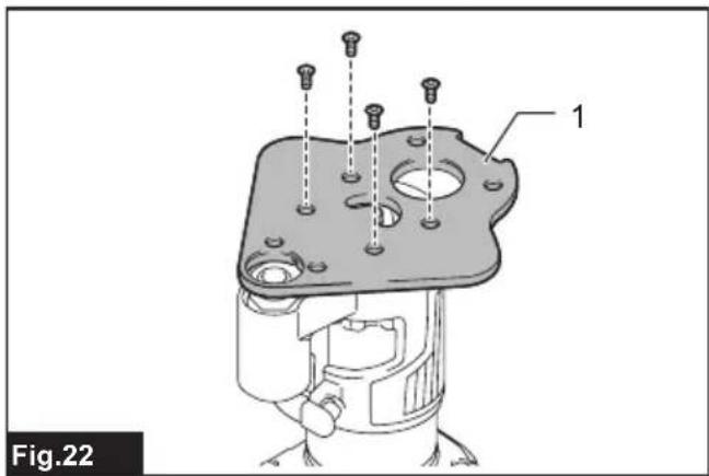
natural_image
Technical line drawing of a mechanical device connected to a coiled cable, labeled Fig.29 (no text or symbols on the diagram itself)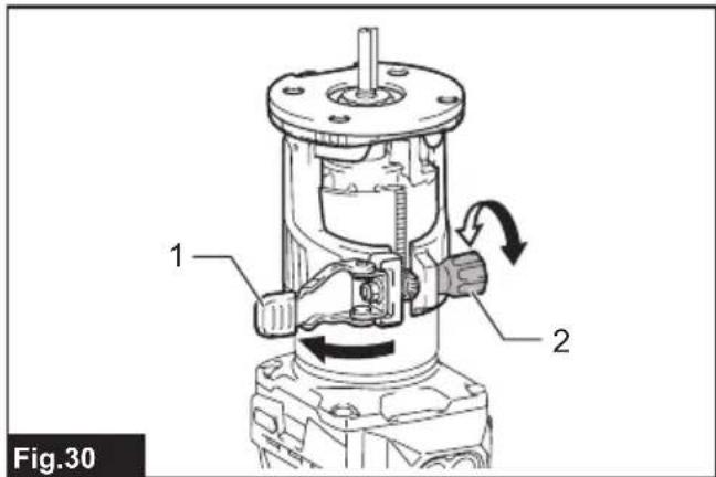
natural_image
Diagram showing a mechanical component with rotational arrows indicating motion, labeled Fig.42 (no text or symbols on the diagram itself)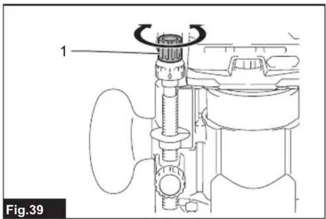
natural_image
Technical diagram of a mechanical assembly with labeled component (no text or symbols beyond label)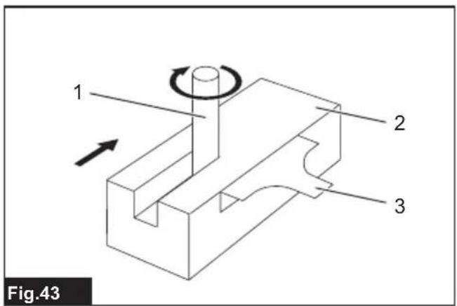
natural_image
Technical line drawing of a mechanical device with labeled parts and directional arrows (no text or symbols beyond labels)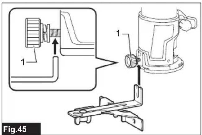
natural_image
Mechanical assembly diagram showing a lever mechanism with rotating components and directional arrows (no text or symbols)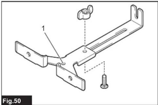
natural_image
Illustration of a hand using a tool to press or install a mechanical component, with an arrow indicating motion (no text or symbols present)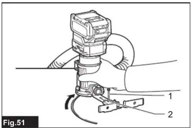
natural_image
Technical diagram of a hand operating a mechanical device with labeled parts (no text or symbols present)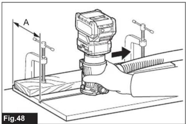
natural_image
Technical line drawing of a mechanical bracket assembly with a screw and mounting hole (no text or symbols)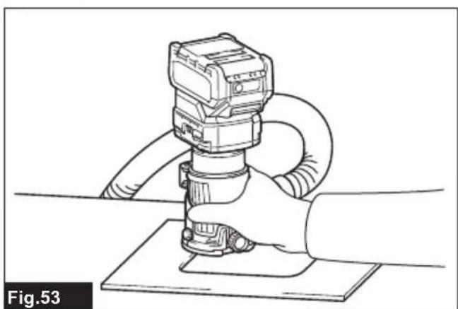
natural_image
Line drawing of a hand operating a mechanical device with hoses and a base plate (no text or symbols)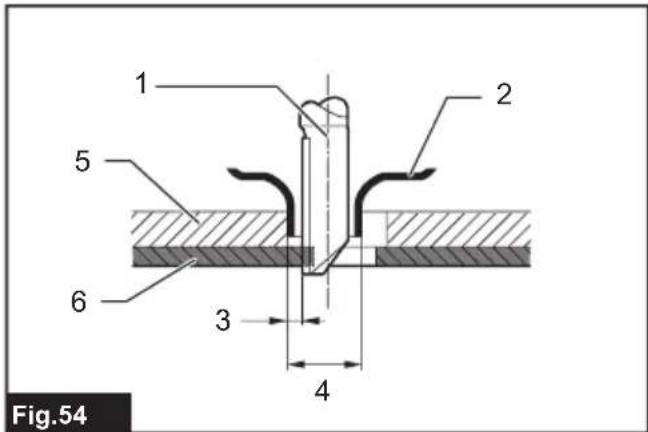
natural_image
Line drawing of a hand holding a handheld device with a hose, no text or symbols present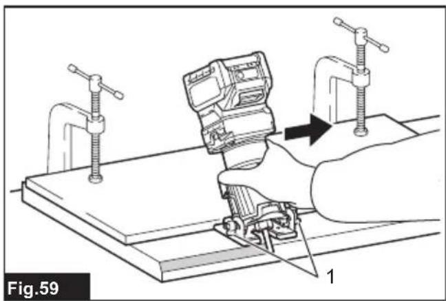
natural_image
Diagram of a hand using a clamp tool to adjust or install a mechanical component, with no visible text or symbols.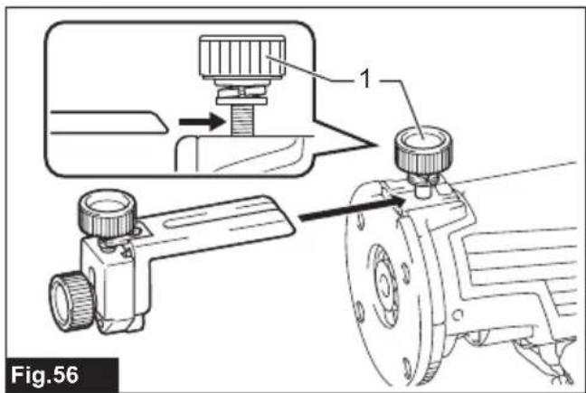
natural_image
Mechanical assembly diagram showing a hand operating a workpiece on a workbench, with no visible text or symbols.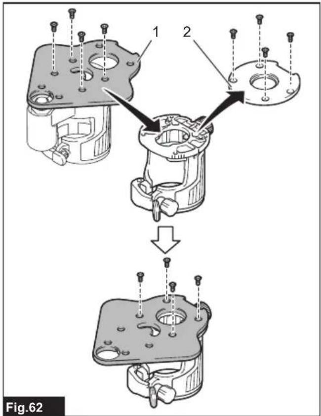
natural_image
Mechanical assembly diagram showing a sewing machine with a clamping tool and directional arrows (no text or symbols)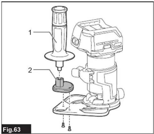
natural_image
Technical line drawing of a mechanical device with an arrow indicating motion (no text or symbols)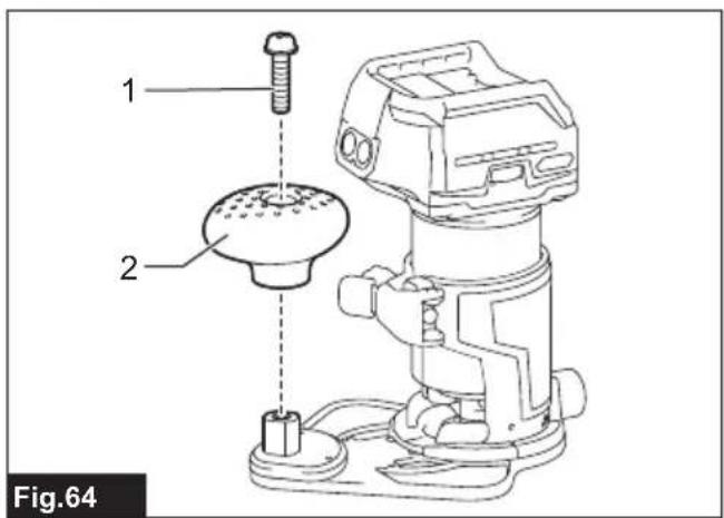
natural_image
Line drawing of hands operating a mechanical device with hoses and tubing (no text or symbols)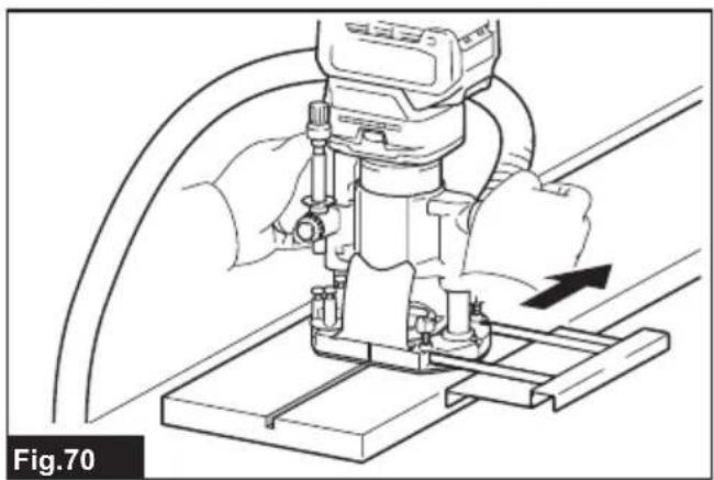
natural_image
Technical line drawing of a mechanical assembly with a hand operating a workpiece (no text or symbols)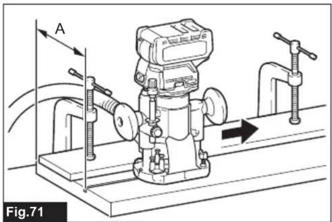
natural_image
Technical line drawing of a mechanical device with directional arrows indicating motion or flow (no text or symbols)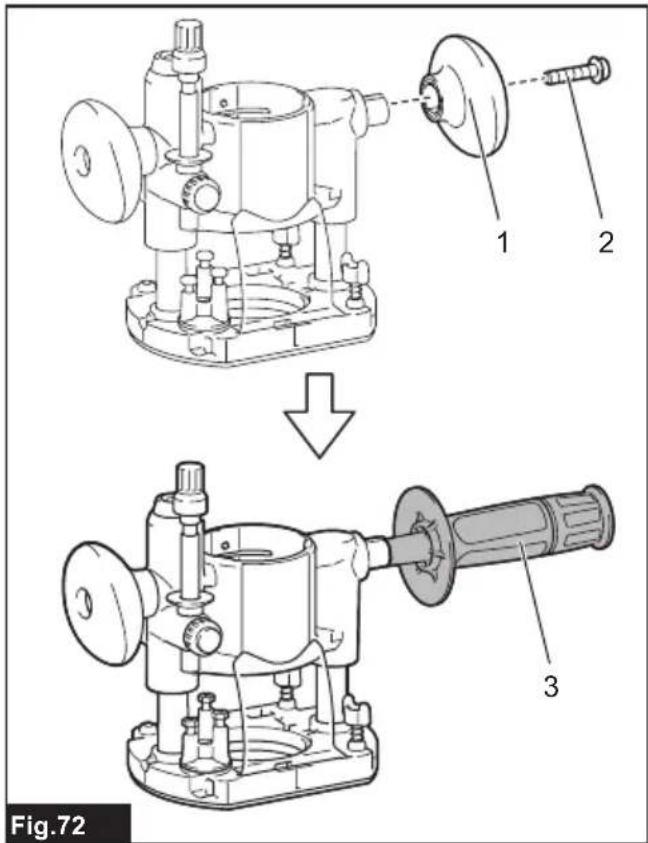
natural_image
Diagram of a pump connected to a hose, showing fluid flow direction (no text or symbols)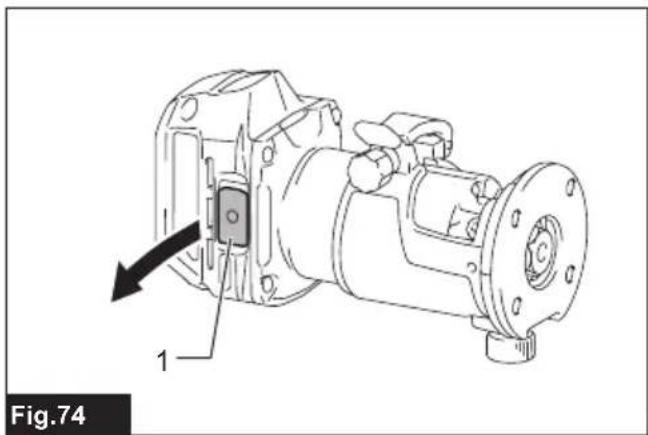
natural_image
Technical line drawing of a mechanical assembly with component 1, no visible text or symbols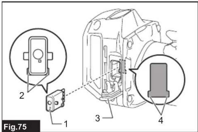
natural_image
Line drawing of a mechanical device with hoses and connectors, labeled Fig.79 (no text or symbols on the diagram itself)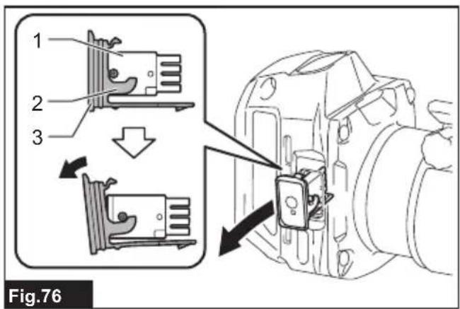
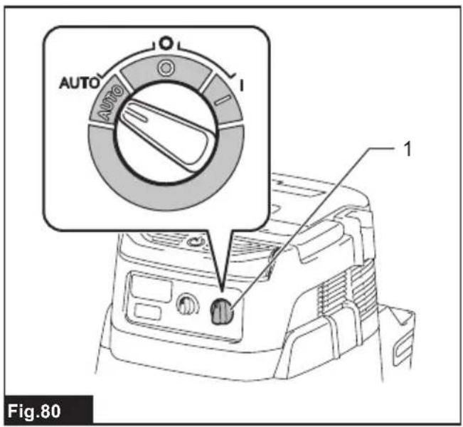
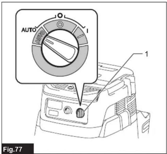
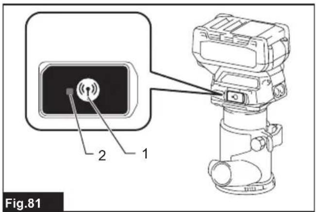
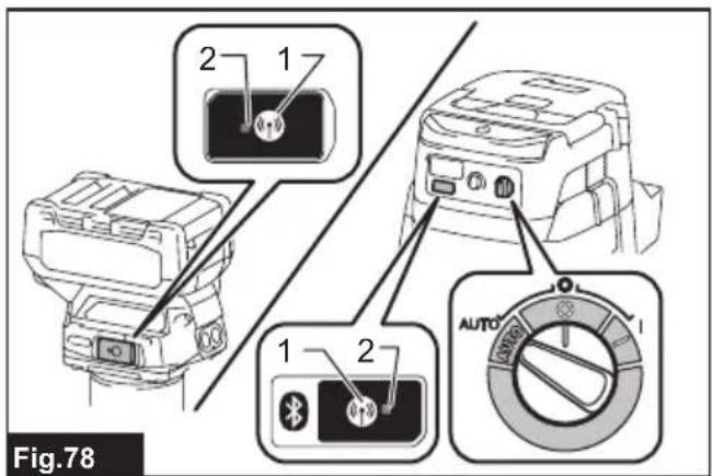
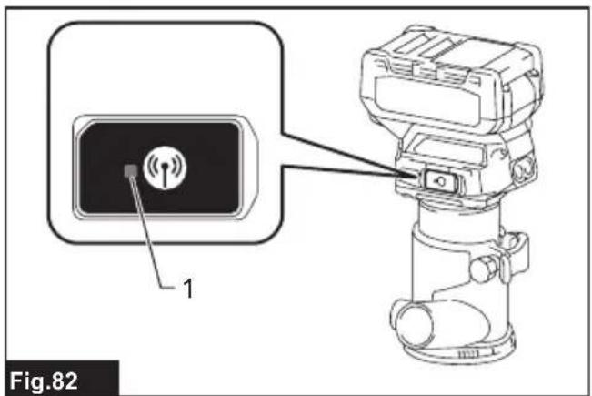
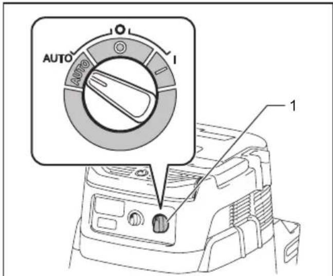
Fig.83
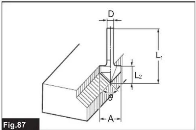
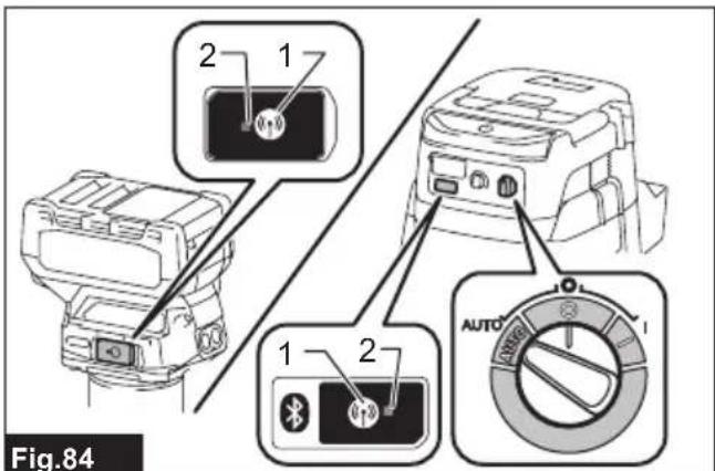
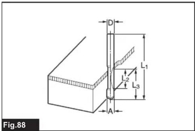
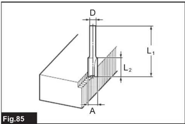
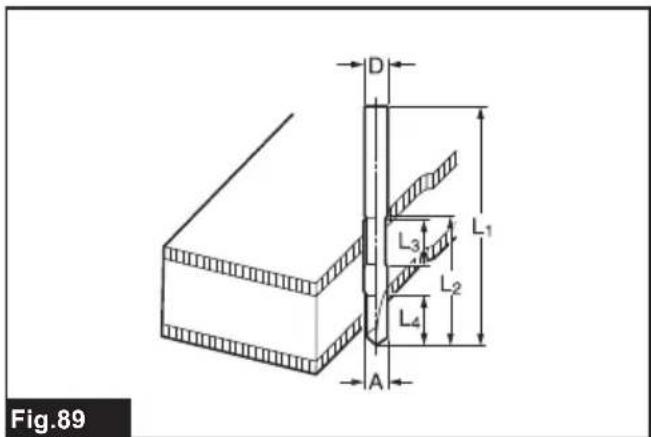
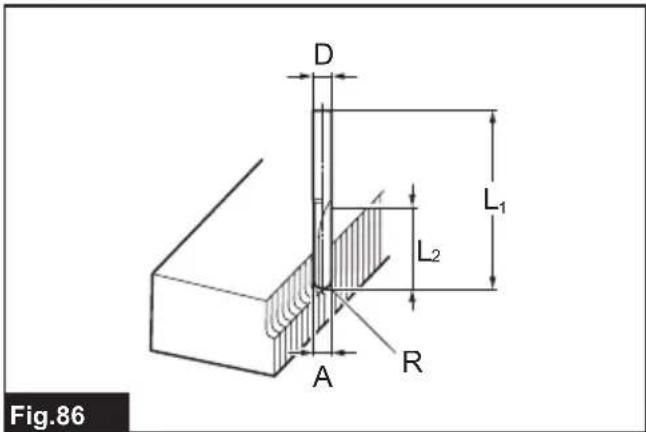
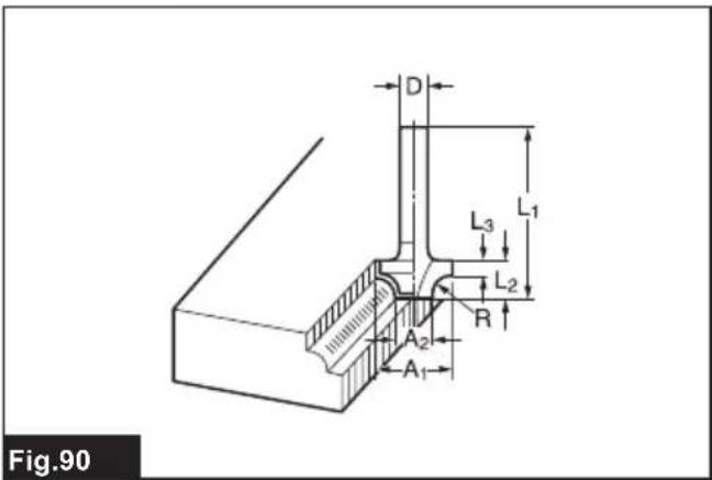
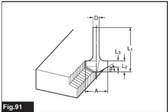
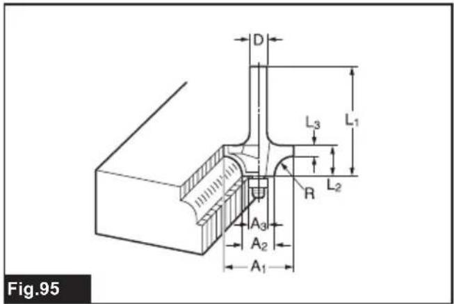
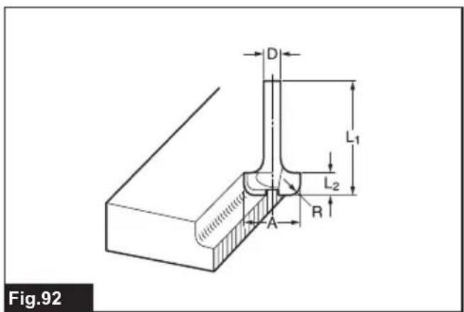
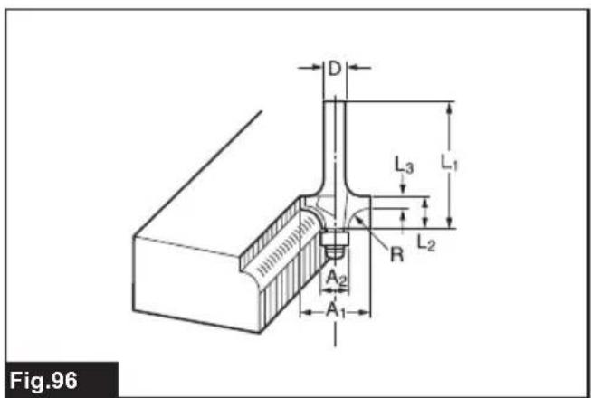
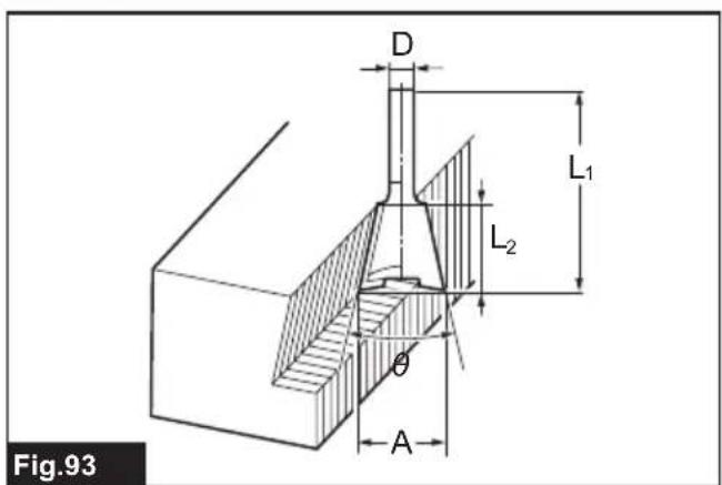
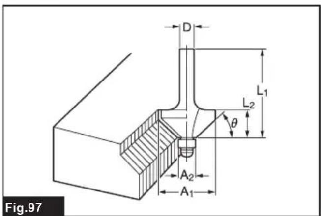
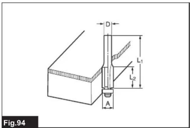
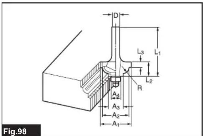
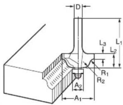
Fig.99
natural_image
Technical line drawing of a mechanical device with no visible text or symbols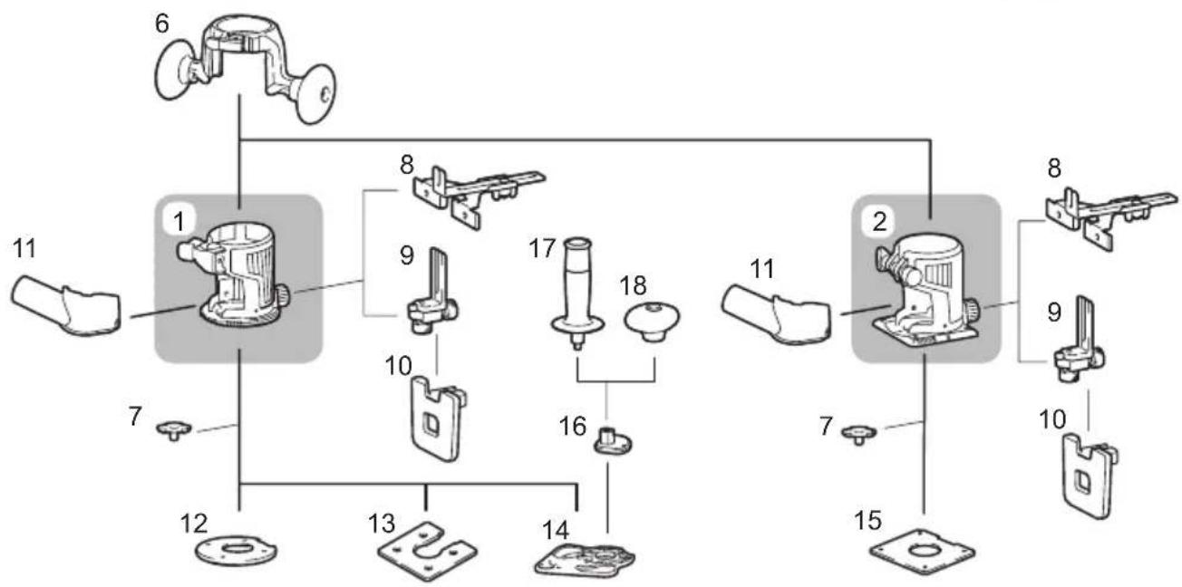
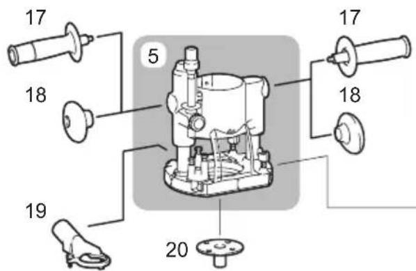
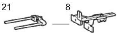
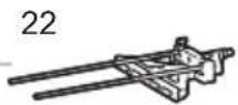
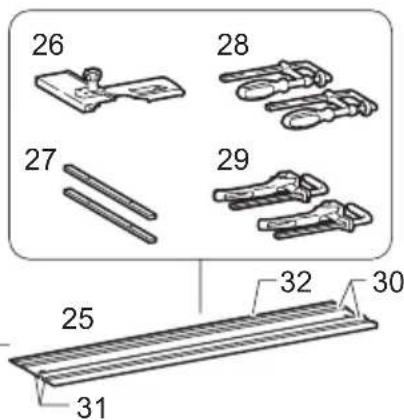
Fig.100
SPECIFICATIONS
| Model: RT001G | ||
| Collet chuck capacity 6 mm, 8 mm, or 1/4" | ||
| No load speed 10,000 - 31,000 min | -1 | |
| Overall height with BL4025 245 mm | ||
| with BL4040 251 mm | ||
| Rated voltage D.C. 36 V - 40 V max | ||
| Net weight 2.2 - 2.5 kg | ||
- Due to our continuing program of research and development, the specifications herein are subject to change without notice.
- Specifications and battery cartridge may differ from country to country.
- The weight may differ depending on the attachment(s), including the battery cartridge. The lightest and heaviest combinations, according to EPTA-Procedure 01/2014, are shown in the table.
Applicable battery cartridge and charger
| Battery cartridge BL4020 / BL4025 / BL4040 | |
| Charger DC40RA / DC40RB / DC40RC |
- Some of the battery cartridges and chargers listed above may not be available depending on your region of residence.
WARNING: Only use the battery cartridges and chargers listed above. Use of any other battery cartridges and chargers may cause injury and/or fire.
Intended use
The tool is intended for flush trimming and profiling of wood, plastic and similar materials.
Noise
The typical A-weighted noise level determined according to EN62841-2-17:
Work mode: rotation without load
Sound pressure level ( L_pA ): 84 dB (A)
Sound power level ( L_WA ): 92 dB (A)
Uncertainty (K) : 3 dB (A)
NOTE: The declared noise emission value(s) has been measured in accordance with a standard test method and may be used for comparing one tool with another.
NOTE: The declared noise emission value(s) may also be used in a preliminary assessment of exposure.
WARNING: Wear ear protection.
WARNING: The noise emission during actual use of the power tool can differ from the declared value(s) depending on the ways in which the tool is used especially what kind of workpiece is processed.
⚠ WARNING: Be sure to identify safety measures to protect the operator that are based on an estimation of exposure in the actual conditions of use (taking account of all parts of the operating cycle such as the times when the tool is switched off and when it is running idle in addition to the trigger time).
Vibration
The vibration total value (tri-axial vector sum) determined according to EN62841-2-17:
Work mode: rotation without load
Vibration emission (ah): 2.5 m/s ^2 or less
Uncertainty (K) : 1.5 m/s ^4
NOTE: The declared vibration total value(s) has been measured in accordance with a standard test method and may be used for comparing one tool with another.
NOTE: The declared vibration total value(s) may also be used in a preliminary assessment of exposure.
⚠ WARNING: The vibration emission during actual use of the power tool can differ from the declared value(s) depending on the ways in which the tool is used especially what kind of workpiece is processed.
WARNING: Be sure to identify safety measures to protect the operator that are based on an estimation of exposure in the actual conditions of use (taking account of all parts of the operating cycle such as the times when the tool is switched off and when it is running idle in addition to the trigger time).
Declarations of Conformity
For European countries only
The Declarations of conformity are included in Annex A to this instruction manual.
SAFETY WARNINGS
General power tool safety warnings
⚠ WARNING Read all safety warnings, instructions, illustrations and specifications provided with this power tool. Failure to follow all instructions listed below may result in electric shock, fire and/or serious injury.
Save all warnings and instructions for future reference.
The term "power tool" in the warnings refers to your mains-operated (corded) power tool or battery-operated (cordless) power tool.
Cordless trimmer safety warnings
- Use clamps or another practical way to secure and support the workpiece to a stable platform. Holding the work by your hand or against the body leaves it unstable and may lead to loss of control.
- Hold the power tool by insulated gripping surfaces only, because the cutter may contact hidden wiring. Cutting a "live" wire may make exposed metal parts of the power tool "live" and could give the operator an electric shock.
- Only use a trimmer bit that is rated at least equal to the maximum speed marked on the tool. If the tool has a variable speed control function, set the tool speed under the speed rating of the trimmer bit.
- The trimmer bit shank must match the designed collet chuck.
- Wear hearing protection during extended period of operation.
- Handle the trimmer bits very carefully.
- Check the trimmer bit carefully for cracks or damage before operation. Replace cracked or damaged trimmer bit immediately.
- Avoid cutting nails. Inspect for and remove all
nails from the workpiece before operation.
-
Hold the tool firmly.
-
Keep hands away from rotating parts.
- Make sure the trimmer bit is not contacting the workpiece before the switch is turned on.
- Before using the tool on an actual workpiece, let it run for a while. Watch for vibration or wobbling that could indicate improperly installed trimmer bit.
- Be careful of the trimmer bit rotating direction and the feed direction.
- Do not leave the tool running. Operate the tool only when hand-held.
- Always switch off and wait for the trimmer bit to come to a complete stop before removing the tool from workpiece.
- Do not touch the trimmer bit immediately after operation; it may be extremely hot and could burn your skin.
- Do not smear the base carelessly with thinner, gasoline, oil or the like. They may cause cracks in the base.
- Use trimmer bits of the correct shank diameter suitable for the speed of the tool.
- Some material contains chemicals which may be toxic. Take caution to prevent dust inhalation and skin contact. Follow material supplier safety data.
- Always use the correct dust mask/respirator for the material and application you are working with.
SAVE THESE INSTRUCTIONS.
WARNING: DO NOT let comfort or familiarity with product (gained from repeated use) replace strict adherence to safety rules for the subject product. MISUSE or failure to follow the safety rules stated in this instruction manual may cause serious personal injury.
Important safety instructions for battery cartridge
- Before using battery cartridge, read all instructions and cautionary markings on (1) battery charger, (2) battery, and (3) product using battery.
- Do not disassemble or tamper with the battery cartridge. It may result in a fire, excessive heat, or explosion.
- If operating time has become excessively shorter, stop operating immediately. It may result in a risk of overheating, possible burns and even an explosion.
- If electrolyte gets into your eyes, rinse them out with clear water and seek medical attention right away. It may result in loss of your eyesight.
- Do not short the battery cartridge:
(1) Do not touch the terminals with any conductive material.
(2) Avoid storing battery cartridge in a container with other metal objects such as
nails, coins, etc.
(3) Do not expose battery cartridge to water or rain.
A battery short can cause a large current flow, overheating, possible burns and even a breakdown.
- Do not store and use the tool and battery cartridge in locations where the temperature may reach or exceed 50 °C (122 °F).
- Do not incinerate the battery cartridge even if it is severely damaged or is completely worn out. The battery cartridge can explode in a fire.
- Do not nail, cut, crush, throw, drop the battery cartridge, or hit against a hard object to the battery cartridge. Such conduct may result in a fire, excessive heat, or explosion.
- Do not use a damaged battery.
- The contained lithium-ion batteries are subject to the Dangerous Goods Legislation requirements. For commercial transports e.g. by third parties, forwarding agents, special requirement on packaging and labeling must be observed. For preparation of the item being shipped, consulting an expert for hazardous material is required. Please also observe possibly more detailed national regulations. Tape or mask off open contacts and pack up the battery in such a manner that it cannot move around in the packaging.
- When disposing the battery cartridge, remove it from the tool and dispose of it in a safe place. Follow your local regulations relating to disposal of battery.
- Use the batteries only with the products specified by Makita. Installing the batteries to non-compliant products may result in a fire, excessive heat, explosion, or leak of electrolyte.
- If the tool is not used for a long period of time, the battery must be removed from the tool.
- During and after use, the battery cartridge may take on heat which can cause burns or low temperature burns. Pay attention to the handling of hot battery cartridges.
- Do not touch the terminal of the tool immediately after use as it may get hot enough to cause burns.
- Do not allow chips, dust, or soil stuck into the terminals, holes, and grooves of the battery cartridge. It may cause heating, catching fire, burst and malfunction of the tool or battery cartridge, resulting in burns or personal injury.
- Unless the tool supports the use near high-voltage electrical power lines, do not use the battery cartridge near high-voltage electrical power lines. It may result in a malfunction or breakdown of the tool or battery cartridge.
- Keep the battery away from children.
SAVE THESE INSTRUCTIONS.

CAUTION: Only use genuine Makita batteries.
Use of non-genuine Makita batteries, or batteries that have been altered, may result in the battery bursting causing fires, personal injury and damage. It will also void the Makita warranty for the Makita tool and charger.
Tips for maintaining maximum battery life
- Charge the battery cartridge before completely discharged. Always stop tool operation and charge the battery cartridge when you notice less tool power.
- Never recharge a fully charged battery cartridge. Overcharging shortens the battery service life.
- Charge the battery cartridge with room temperature at 10 °C - 40 °C (50 °F - 104 °F). Let a hot battery cartridge cool down before charging it.
- When not using the battery cartridge, remove it from the tool or the charger.
- Charge the battery cartridge if you do not use it for a long period (more than six months).
Important safety instructions for wireless unit
- Do not disassemble or tamper with the wireless unit.
- Keep the wireless unit away from young children. If accidentally swallowed, seek medical attention immediately.
- Use the wireless unit only with Makita tools.
- Do not expose the wireless unit to rain or wet conditions.
- Do not use the wireless unit in places where the temperature exceeds 50 °C ( 122 °F ).
- Do not operate the wireless unit in places where medical instruments, such as heart pace makers are nearby.
- Do not operate the wireless unit in places where automated devices are nearby. If operated, automated devices may develop malfunction or error.
- Do not operate the wireless unit in places under high temperature or places where static electricity or electrical noise could be generated.
- The wireless unit can produce electromagnetic fields (EMF) but they are not harmful to the user.
- The wireless unit is an accurate instrument. Be careful not to drop or strike the wireless unit.
- Avoid touching the terminal of the wireless unit with bare hands or metallic materials.
- Always remove the battery on the product when installing the wireless unit into it.
- When opening the lid of the slot, avoid the place where dust and water may come into the slot. Always keep the inlet of the slot clean.
- Always insert the wireless unit in the correct
direction.
- Do not press the wireless activation button on the wireless unit too hard and/or press the button with an object with a sharp edge.
- Always close the lid of the slot when operating.
- Do not remove the wireless unit from the slot while the power is being supplied to the tool. Doing so may cause a malfunction of the wireless unit.
- Do not remove the sticker on the wireless unit.
- Do not put any sticker on the wireless unit.
- Do not leave the wireless unit in a place where static electricity or electrical noise could be generated.
- Do not leave the wireless unit in a place subject to high heat, such as a car sitting in the sun.
- Do not leave the wireless unit in a dusty or powdery place or in a place corrosive gas could be generated.
- Sudden change of the temperature may bedew the wireless unit. Do not use the wireless unit until the dew is completely dried.
- When cleaning the wireless unit, gently wipe with a dry soft cloth. Do not use benzine, thinner, conductive grease or the like.
- When storing the wireless unit, keep it in the supplied case or a static-free container.
- Do not insert any devices other than Makita wireless unit into the slot on the tool.
- Do not use the tool with the lid of the slot damaged. Water, dust, and dirt come into the slot may cause malfunction.
- Do not pull and/or twist the lid of the slot more than necessary. Restore the lid if it comes off from the tool.
- Replace the lid of the slot if it is lost or damaged.
SAVE THESE INSTRUCTIONS.
FUNCTIONAL DESCRIPTION
⚠️CAUTION: Always be sure that the tool is switched off and the battery cartridge is removed before adjusting or checking function on the tool.
Installing or removing battery cartridge
⚠️ CAUTION: Always switch off the tool before installing or removing of the battery cartridge.
CAUTION: Hold the tool and the battery cartridge firmly when installing or removing battery cartridge. Failure to hold the tool and the battery cartridge firmly may cause them to slip off your hands and result in damage to the tool and battery cartridge and a personal injury.
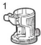
To remove the battery cartridge, slide it from the tool while sliding the button on the front of the cartridge.
▶ Fig.1: 1. Red indicator 2. Button 3. Battery cartridge
To install the battery cartridge, align the tongue on the battery cartridge with the groove in the housing and slip it into place. Insert it all the way until it locks in place with a little click. If you can see the red indicator on the upper side of the button, it is not locked completely.
CAUTION: Always install the battery cartridge fully until the red indicator cannot be seen. If not, it may accidentally fall out of the tool, causing injury to you or someone around you.
CAUTION: Do not install the battery cartridge forcibly. If the cartridge does not slide in easily, it is not being inserted correctly.
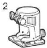
Indicating the remaining battery capacity
Press the check button on the battery cartridge to indicate the remaining battery capacity. The indicator lamps light up for a few seconds.
▶ Fig.2: 1. Indicator lamps 2. Check button
| Indicator lamps Remaining | capacity | |||
| Gmail | Gmail | Gmail | Gmail | |
| Lighted Off | Blinking | |||
| Gmail | Gmail | Gmail | 75% to 100% | |
| Gmail | Gmail | Gmail | 50% to 75% | |
| Gmail | Gmail | Gmail | 25% to 50% | |
| Gmail | Gmail | Gmail | 0% to 25% | |
| Gmail | Gmail | Gmail | Charge the battery. | |
| Gmail | Gmail | Gmail | The battery may have malfunctioned. | |
NOTE: Depending on the conditions of use and the ambient temperature, the indication may differ slightly from the actual capacity.
NOTE: The first (far left) indicator lamp will blink when the battery protection system works.
Tool / battery protection system
The tool is equipped with a tool/battery protection system. This system automatically cuts off power to the motor to extend tool and battery life. The tool will automatically stop during operation if the tool or battery is placed under one of the following conditions:
Overload protection
When the battery is operated in a manner that causes it to draw an abnormally high current, the tool automatically stops without any indication. In this situation, turn the tool off and stop the application that caused the tool to become overloaded. Then turn the tool on to restart.
Overheat protection
When the tool or battery is overheated, the tool stops automatically. In this case, let the tool and battery cool before turning the tool on again.
Overdischarge protection
When the battery capacity is not enough, the tool stops automatically. In this case, remove the battery from the tool and charge the battery.
Protections against other causes
Protection system is also designed for other causes that could damage the tool and allows the tool to stop automatically. Take all the following steps to clear the causes, when the tool has been brought to a temporary halt or stop in operation.
- Turn the tool off, and then turn it on again to restart.
- Charge the battery(ies) or replace it/them with recharged battery(ies).
- Let the tool and battery(ies) cool down.
If no improvement can be found by restoring protection system, then contact your local Makita Service Center.
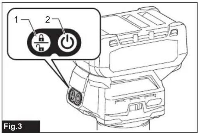
Switch action
To turn on the tool, press the lock/unlock button. The tool turns into the standby mode. To start the tool, press the start/stop button in the standby mode. To stop the tool, press the start/stop button again. The tool turns into the standby mode. To turn off the tool, press the lock/unlock button in the standby mode.
▶ Fig.3: 1. Lock/unlock button 2. Start/stop button
NOTE: If the tool is left for 10 seconds without any operation in the standby mode, the tool automatically turns off and the lamp goes off.
NOTE: You can also stop and turn off the tool by pressing the lock/unlock button while the tool is operating.
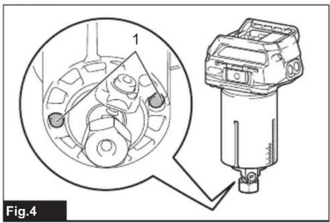
Lighting up the front lamp
⚠️ CAUTION: Do not look in the light or see the source of light directly.
To turn on the lamp, press the lock/unlock button. To turn off the lamp, press the lock/unlock button again.
NOTICE: When the tool is overheated, the lamp blinks. Cool down the tool fully before operating the tool again.
NOTE: Use a dry cloth to wipe the dirt off the lens of the lamp. Be careful not to scratch the lens of the lamp, or it may lower the illumination.
▶ Fig.4: 1. Lamp
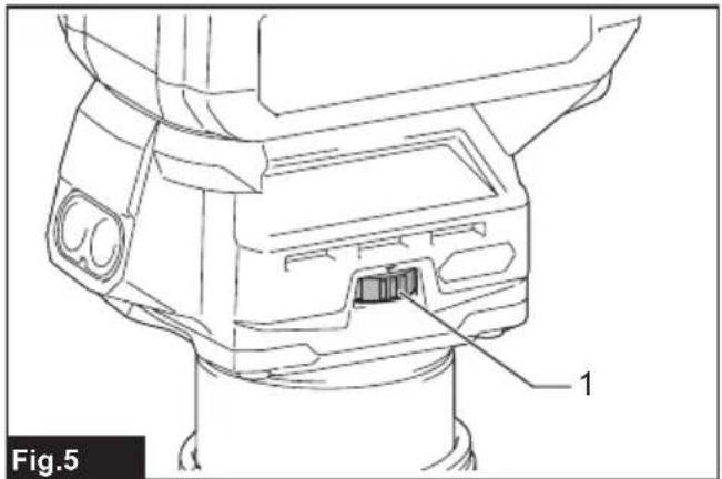
Speed adjusting dial
The rotation speed of the tool can be changed by turning the speed adjusting dial. The table below shows the number on the dial and the corresponding rotation speed.
▶ Fig.5: 1. Speed adjusting dial
| Number Speed | |
| 1 10,000 min | -1 |
| 2 15,000 min | -1 |
| 3 21,000 min | -1 |
| 4 26,000 min | -1 |
| 5 31,000 min | -1 |
CAUTION: Do not change the rotation speed during operation. Otherwise unexpected reaction of the tool may cause an injury.
NOTICE: If the tool is operated continuously at low speed for a long time, the motor will get overloaded, resulting in tool malfunction.
NOTICE: The speed adjusting dial can be turned only as far as 5 and back to 1. Do not force it past 5 or 1, or the speed adjusting function may no longer work.
Electronic function
The tool is equipped with the electronic functions for easy operation.
- Constant speed control
The speed control function provides the constant rotation speed regardless of load conditions. - Soft start
The soft-start function minimizes start-up shock, and makes the tool start smoothly.
- Soft brake
The tool stops gently with the soft brake. The soft brake prevents damage to the workpiece due to recoil and allows you to start next operation earlier.
If the tool consistently fails to stop the trimmer bit after the switch is turned off, have the tool serviced at a Makita service center.
ASSEMBLY
⚠️CAUTION: Always be sure that the tool is switched off and the battery cartridge is removed before carrying out any work on the tool.
Installing or removing trimmer bit
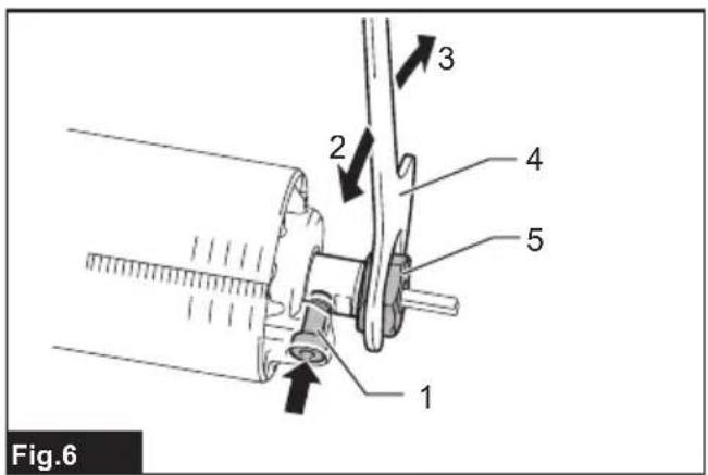
NOTICE: Do not tighten the collet nut without installing a trimmer bit, or the collet cone may break.
Insert the trimmer bit all the way into the collet cone. Press the shaft lock and tighten the collet nut with the wrench.
▶ Fig.6: 1. Shaft lock 2. Loosen 3. Tighten 4. Wrench 5. Collet nut
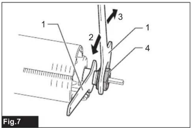
You can also tighten the collet nut securely with the two wrenches.
▶ Fig.7: 1. Wrench 2. Loosen 3. Tighten 4. Collet nut
To remove the trimmer bit, follow the installation procedure in reverse.
NOTE: The shaft lock may not return to the original position when you tighten the collet nut in the installation of the trimmer bit. The shaft lock returns to the original position when you start the tool.
▶ Fig.8: 1. Shaft lock
Changing the collet cone
⚠️CAUTION: Use the correct size collet cone for the trimmer bit which you intended to use.
⚠️CAUTION: Do not tighten the collet nut without installing a trimmer bit, or the collet cone may break.
- Loosen the collet nut and remove.
- Replace the installed collet cone with desired collet cone.
- Reinstall collet nut.
▶ Fig.9: 1. Collet cone 2. Collet nut
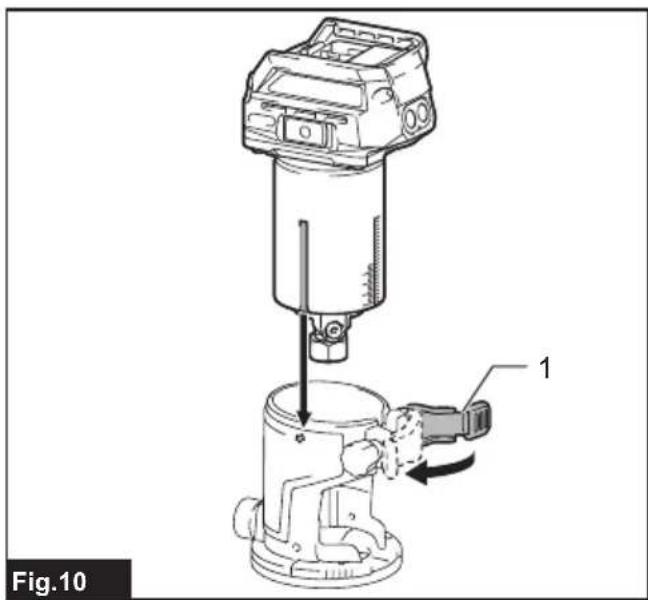
Installing or removing the trimmer base
- Open the lock lever of the trimmer base, then insert the tool into the trimmer base aligning the groove on the tool with the protrusion on the trimmer base.
- Close the lock lever.
▶ Fig.10: 1. Lock lever
NOTE: You can use the trimmer base (resin) as an optional accessory as shown in the figure. When using the trimmer base (resin), loosen or tighten the thumb nut instead of opening or closing the lock lever.
Align the rack on the tool with the spur gear on the trimmer base.
▶ Fig.11: 1. Thumb nut 2. Rack 3. Spur gear
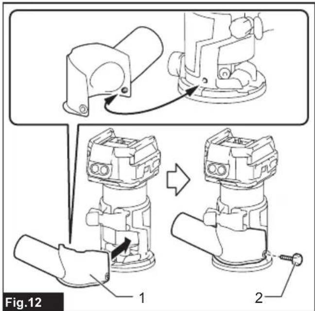
- Attach the dust nozzle to the trimmer base, and then tighten the thumb screw.
▶ Fig.12: 1. Dust nozzle 2. Thumb screw
▶ Fig.13
To remove the base, follow the installation procedure in reverse.
CAUTION: When using the tool with the trim-mer base, be sure to install the dust nozzle on the trimmer base.
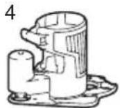
Installing or removing the tilt base
Optional accessory
- Open the lock lever of the tilt base, then insert the tool into the tilt base aligning the groove on the tool with the protrusion on the tilt base.
- Close the lock lever.
▶ Fig.14: 1. Lock lever
To remove the base, follow the installation procedure in reverse.
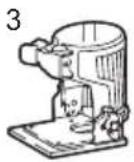
Installing or removing the offset base
Optional accessory
- Press the shaft lock, then loosen the collet nut.
▶ Fig.15: 1. Collet nut 2. Shaft lock 3. Wrench -
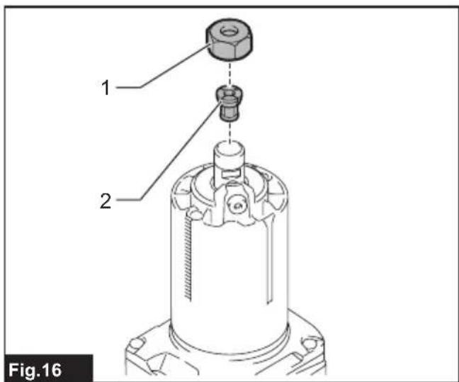
Remove the collet nut and the collet cone.
▶ Fig.16: 1. Collet nut 2. Collet cone -
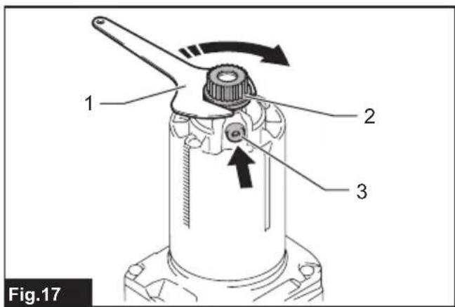
Install the pulley onto the tool by pressing the shaft lock and tightening the pulley with the wrench.
▶ Fig.17: 1. Wrench 2. Pulley 3. Shaft lock
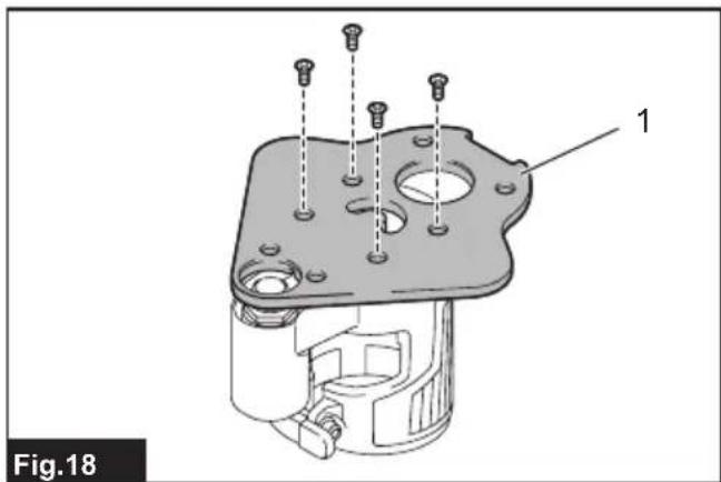
- Loosen the screws on the base plate, and then remove the base plate.
▶ Fig.18: 1. Base plate
- Open the lock lever of the offset base, then attach the offset base to the tool.
▶ Fig.19: 1. Lock lever
- Mount the belt to the pulley with a stick like a slotted screwdriver by rotating the belt manually.
▶ Fig.20: 1. Pulley 2. Belt
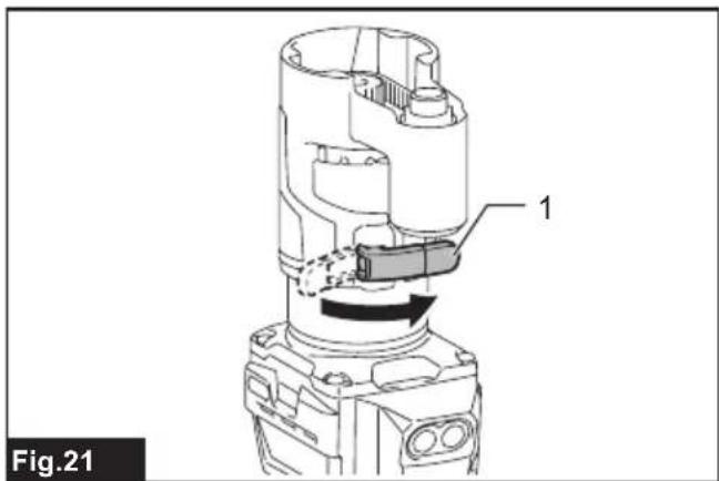
- Close the lock lever.
▶ Fig.21: 1. Lock lever
- Attach the base plate by tightening the screws.
▶ Fig.22: 1. Base plate
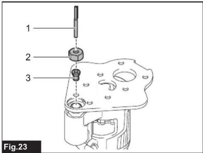
- Insert the collet cone and the trimmer bit into the offset base, and then tighten the collet nut.
▶ Fig.23: 1. Trimmer bit 2. Collet nut 3. Collet cone
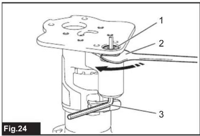
- Insert the hex wrench into the hole of the offset base, and then tighten the collet nut with the wrench.
▶ Fig.24: 1. Collet nut 2. Wrench 3. Hex wrench
To remove the base, follow the installation procedure in reverse.
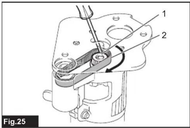
NOTE: You can also mount the belt to the pulley without removing the base plate as shown in the figure.
▶ Fig.25: 1. Pulley 2. Belt
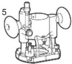
Installing or removing the plunge base
Optional accessory
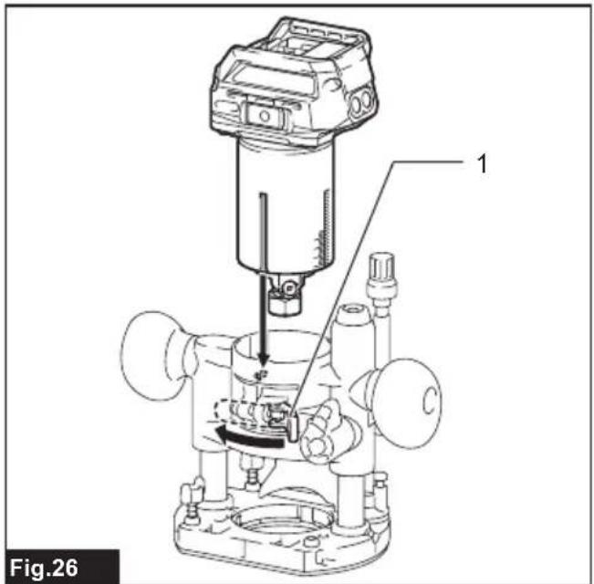
- Open the lock lever of the plunge base, then insert the tool into the plunge base all the way aligning the groove on the tool with the protrusion on the plunge base.
- Close the lock lever.
▶ Fig.26: 1. Lock lever
To remove the base, follow the installation procedure in reverse.
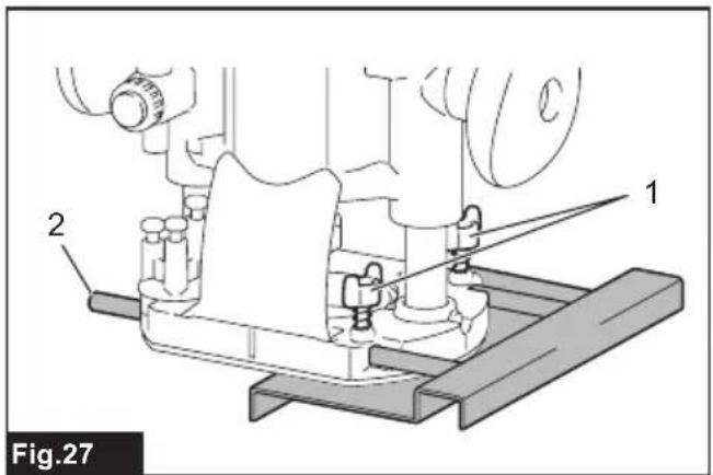
Installing or removing the parallel ruler on the plunge base
Optional accessory
Insert the guide bars into the holes in the plunge base, and then tighten the wing bolts. To remove the ruler, follow the installation procedure in reverse.
▶ Fig.27: 1. Wing bolt 2. Guide bar
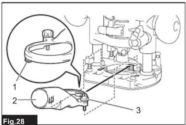
Installing or removing the dust nozzle on the plunge base
Insert the dust nozzle into the plunge base so that the protrusion on the dust nozzle fits in the notch in the plunge base, and then tighten the thumb screw on the dust nozzle. To remove the nozzle, follow the installation procedure in reverse.
▶ Fig.28: 1. Protrusion 2. Dust nozzle 3. Thumb screw
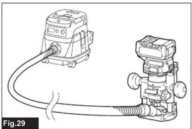
▶ Fig.29
OPERATION
Adjusting cutting depth
To adjust the cutting depth, open the lock lever, then move the tool base up or down by turning the adjusting screw. After the adjustment, close the lock lever firmly.
▶ Fig.30: 1. Lock lever 2. Adjusting screw
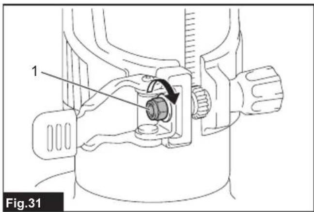
NOTICE: If the tool is not secured after closing the lock lever, tighten the hex nut, and then close the lock lever.
▶ Fig.31: 1. Hex nut
Adjusting cutting depth with the plunge base
Optional accessory
- Place the tool on the flat surface.
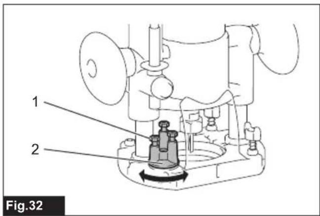
- Select the stopper screw by rotating the stopper base.
▶ Fig.32: 1. Stopper screw 2. Stopper base
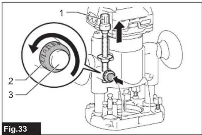
- Loosen the fixing nut, then pull up the stopper pole while pressing the feed button.
▶ Fig.33: 1. Stopper pole 2. Fixing nut 3. Feed button
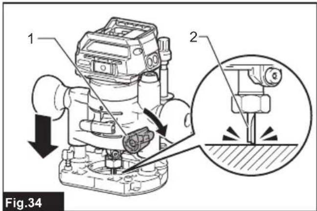
4. Push down the tool until the tip of the trimmer bit touches the flat surface, and then turn the fixing lever to secure the tool.
▶ Fig.34: 1. Fixing lever 2. Trimmer bit
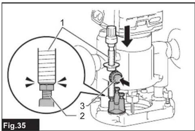
- Press down the stopper pole while pressing the feed button until it contacts the stopper screw.
▶ Fig.35: 1. Stopper pole 2. Stopper screw 3. Feed button
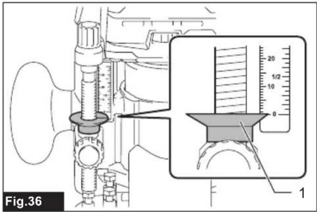
- Slide the depth pointer so that the pointer indicates "0" on the scale.
▶ Fig.36: 1. Depth pointer
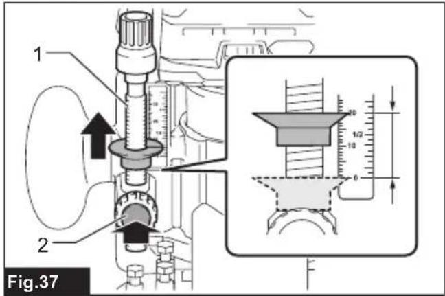
- Adjust the cutting depth by pulling up the stopper pole while pressing the feed button.
▶ Fig.37: 1. Stopper pole 2. Feed button
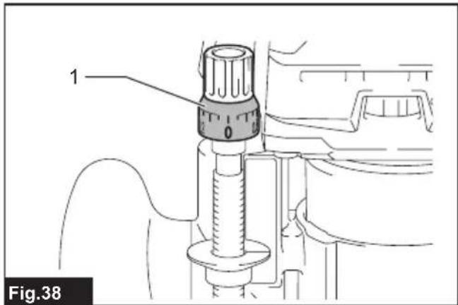
- To perform fine adjustment of the cutting depth, turn the dial on the stopper pole so that it indicates "0".
▶ Fig.38: 1. Dial
- Turn the head of the stopper pole to obtain the desired depth. To increase the depth, turn the head counterclockwise. To decrease the depth, turn the head clockwise. (The depth changes by 1 mm per one revolution.)
▶ Fig.39: 1. Head of the stopper pole
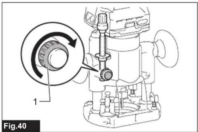
- Tighten the stopper pole fixing nut.
▶ Fig.40: 1. Fixing nut
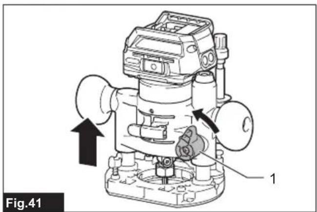
- Release the fixing lever.
▶ Fig.41: 1. Fixing lever
By pushing down the tool until the stopper pole meets the stopper screw, you can obtain the depth of cut which you adjusted by above procedure.
Using the tool with the trimmer base
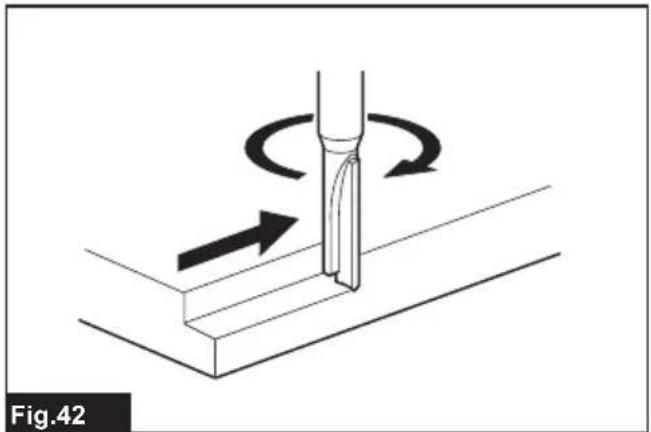
Set the tool base on the workpiece without the trimmer bit making any contact. Turn the tool on and wait until the trimmer bit attains full speed. Move the tool forward over the workpiece surface. Keep the tool base flush while moving the tool.
When cutting the edge, be sure to keep the workpiece surface on the left side of the trimmer bit in the feed direction.
▶ Fig.42
NOTE: Before cutting on the actual workpiece, it is recommended to make a sample cut. The proper feed speed depends on the trimmer bit size, the kind of workpiece, and depth of cut. Moving the tool forward too fast may cause a poor quality of cut, or damage to the trimmer bit or motor. Moving the tool forward too slowly may burn and mar the cutting surface.
When using the trimmer shoe, the straight guide, or the trimmer guide, be sure to keep it on the right side in the feed direction. This will help to keep it flush with the side of the workpiece.
▶ Fig.43: 1. Trimmer bit 2. Workpiece 3. Straight guide
NOTICE: Since excessive cutting may cause overload of the motor or difficulty in controlling the tool, the depth of cut should not be more than 3 mm at a pass when cutting grooves. When you wish to cut grooves more than 3 mm deep, make several passes with progressively deeper trimmer bit settings.
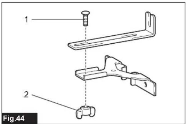
Using the straight guide
- Assemble the straight guide with the bolt and the wing nut.
▶ Fig.44: 1. Bolt 2. Wing nut
- Attach the straight guide to the trimmer base with the clamp screw.
▶ Fig.45: 1. Clamp screw
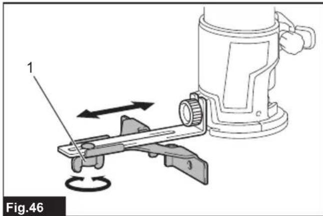
- Loosen the wing nut on the straight guide and adjust the distance between the trimmer bit and the straight guide. At the desired distance, tighten the wing nut.
▶ Fig.46: 1. Wing nut
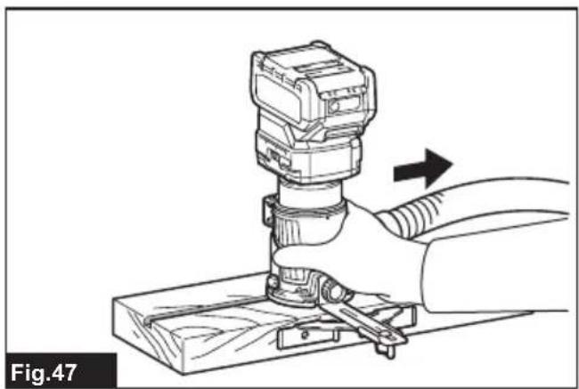
- Move the tool with the straight guide flush with the side of the workpiece.
▶ Fig.47
If the distance (A) between the side of the workpiece and the cutting position is too wide for the straight guide, or if the side of the workpiece is not straight, the straight guide cannot be used.
In this case, firmly clamp a straight board to the workpiece and use it as a guide against the trimmer base. Feed the tool in the direction of the arrow.
▶ Fig.48
Using the straight guide for circular work
For circular work, assemble the straight guide as shown in the figures. The minimum and maximum radius of circles to be cut (distance between the center of circle and the center of trimmer bit) are as follows:
- Minimum: 70 mm
• Maximum: 221 mm
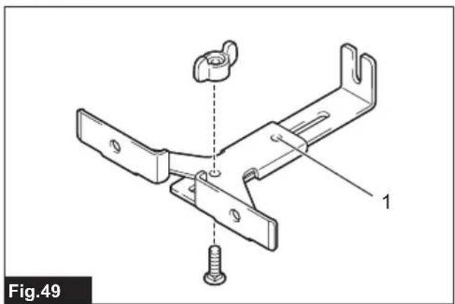
For cutting circles between 70 mm and 121 mm in radius.
▶ Fig.49: 1. Center hole
For cutting circles between 121 mm and 221 mm in radius.
▶ Fig.50: 1. Center hole
NOTE: Circles between 172 mm and 186 mm in radius cannot be cut using this guide.
Align the center hole in the straight guide with the center of the circle to be cut. Drive a nail less than 6 mm in diameter into the center hole to secure the straight guide. Pivot the tool around the nail in the clockwise direction.
▶ Fig.51: 1. Nail 2. Center hole
Using the templet guide
The templet guide allows for repetitive cut with templet patterns by using a templet.
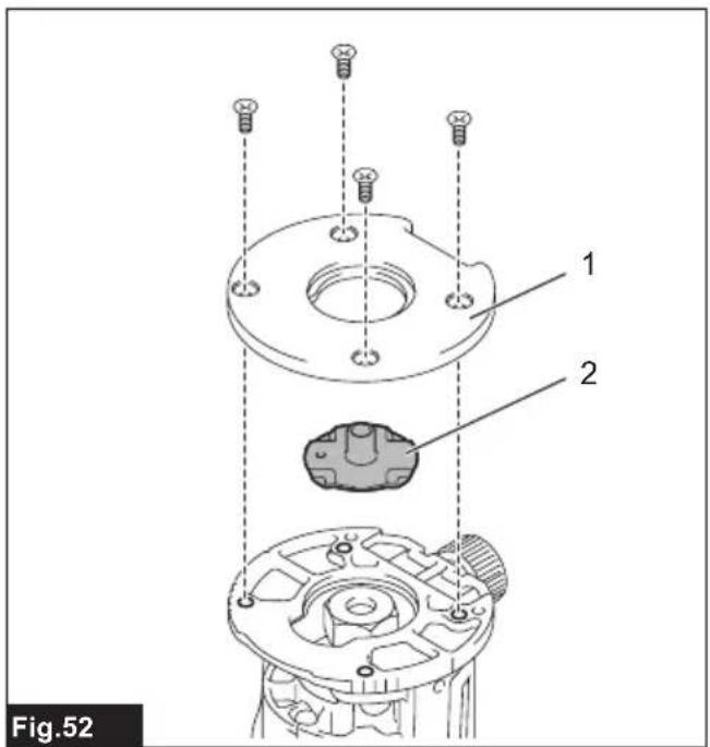
- Loosen the screws on the base plate, and then remove the base plate from the trimmer base.
- Place the templet guide on the base, and then attach the base plate by tightening the screws.
▶ Fig.52: 1. Base plate 2. Templet guide
- Place the tool on the templet and move the tool so that the templet guide slides along the side of the templet.
▶ Fig.53
NOTE: The actual cut size on the workpiece is slightly different from the templet. The difference is the distance (X) between the trimmer bit and the outside of the templet guide. The distance (X) can be calculated by using the following equation:
Distance (X) = (outside diameter of templet guide - trimmer bit diameter) / 2
▶ Fig.54: 1. Trimmer bit 2. Templet guide 3. Distance (X) 4. Outside diameter of templet guide 5. Templet 6. Workpiece
Using the trimmer guide
Optional accessory
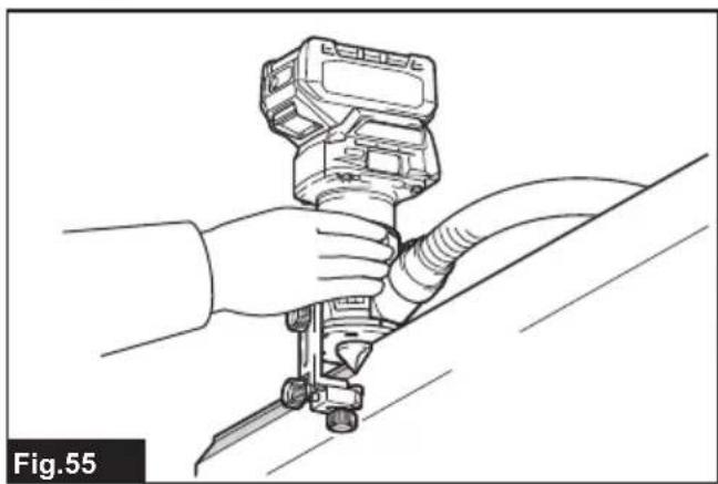
The trimmer guide allows for trimming the curved side like veneers for furniture by moving the guide roller along the side of the workpiece.
▶ Fig.55
- Loosen the clamp screw, then install the trimmer guide on the trimmer base, and then tighten the clamp screw.
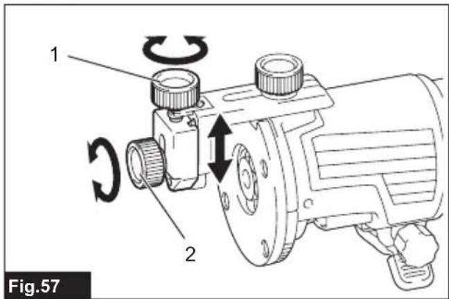
▶ Fig.56: 1. Clamp screw - Loosen the clamp screw and adjust the distance between the trimmer bit and the trimmer guide by turning the adjusting screw (1 mm per turn). At the desired distance, tighten the clamp screw to secure the trimmer guide.
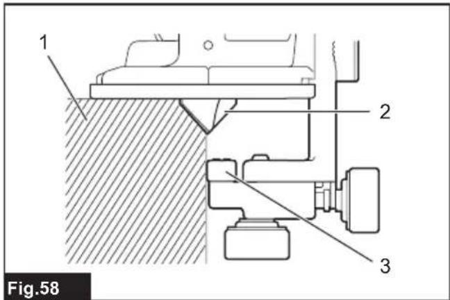
▶ Fig.57: 1. Adjusting screw 2. Clamp screw - Move the tool with the guide roller riding the side of the workpiece.
▶ Fig.58: 1. Workpiece 2. Trimmer bit 3. Guide roller
Using the tool with the tilt base
The tilt base is used for trimming the edge of laminate sheet or similar materials.
The tilt base is convenient for chamfering. Loosen the wing screws, then tilt the tool at the desired angle, and then tighten the wing screws.
Firmly clamp a straight board to the workpiece and use it as a guide against the tilt base. Feed the tool in the direction of the arrow.
▶ Fig.59: 1. Wing screw
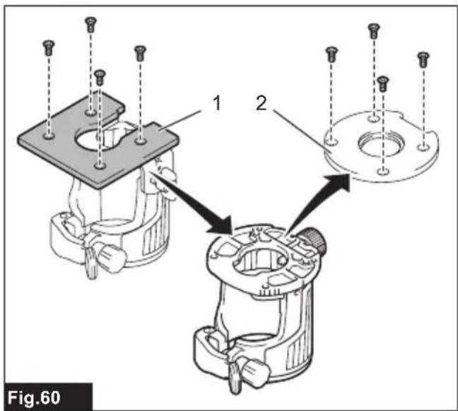
Using the tilt base plate with the trimmer base
To use the trimmer base with a square base plate, remove the base plate from the tilt base, and then attach it to the trimmer base.
▶ Fig.60: 1. Tilt base plate 2. Trimmer base plate
NOTICE: Use screws on the trimmer base when installing the tilt base plate. The screws on the tilt base are shorter than the screws on the trimmer base.
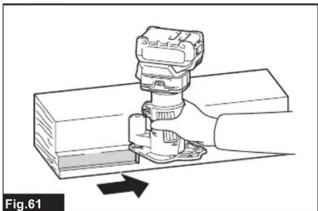
Using the tool with the offset base
The offset base is used for trimming the edge of laminate sheet or similar materials. The offset base is convenient for work in a tight area.
▶ Fig.61
Using the trimmer base with the offset base plate and grip
The offset base plate can also be used with a trimmer base and a grip attachment (optional accessory) for more stability.
- Loosen the screws on the offset base plate, then remove the offset base plate from the offset base.
▶ Fig.62: 1. Offset base plate 2. Trimmer base plate - Attach the offset base plate to the trimmer base by tightening the screws.
- Attach the grip attachment and the bar type grip to the offset base plate by tightening the screws.
▶ Fig.63: 1. Bar type grip 2. Grip attachment
The knob type grip removed from the plunge base can be installed on the offset base instead of the bar type grip.
▶ Fig.64: 1. Screw 2. Knob type grip
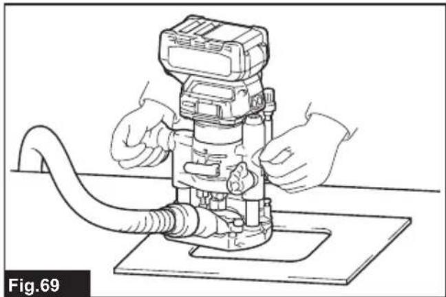
Using the tool with the plunge base
Always hold the grips firmly with both hands during operation. Operate the tool in the same way as the trimmer base.
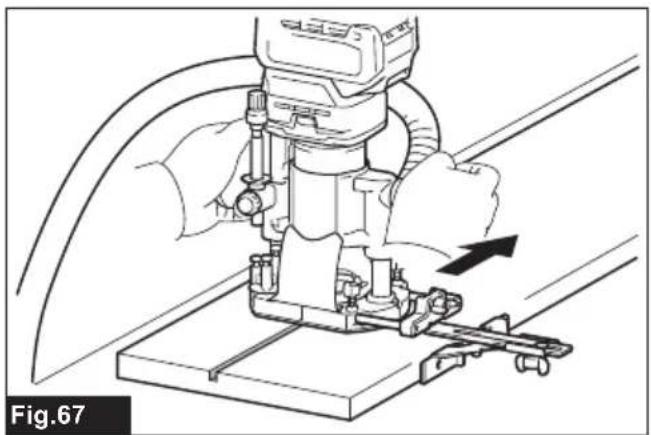
Using the straight guide
Optional accessory
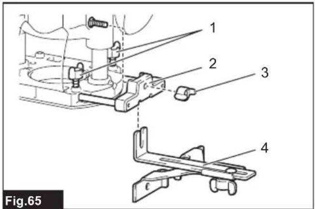
- Install the straight guide to the guide holder by tightening the wing nut. Insert the guide holder into the holes in the plunge base, and then tighten the wing bolts.
▶ Fig.65: 1. Wing bolt 2. Guide holder 3. Wing nut 4. Straight guide
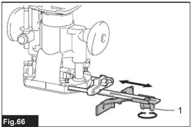
- Loosen the wing nut on the straight guide and adjust the distance between the trimmer bit and the straight guide. At the desired distance, tighten the wing nut.
▶ Fig.66: 1. Wing nut
- Operate the tool in the same way as the straight guide for the trimmer base.
▶ Fig.67
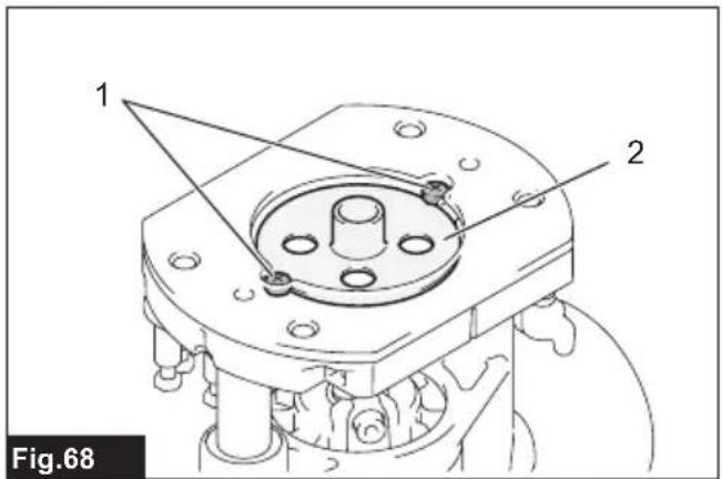
Using the templet guide
Optional accessory
- Loosen the screws on the base and remove them. Place the templet guide on the base, and then tighten the screws.
▶ Fig.68: 1. Screw 2. Templet guide - Operate the tool in the same way as the templet guide for the trimmer base.
▶ Fig.69
Using the parallel ruler
The parallel ruler is effectively used for straight cuts when chamfering or grooving. Adjust the distance between the trimmer bit and the parallel ruler. At the desired distance, tighten the wing bolts to secure the parallel ruler. When cutting, move the tool with the parallel ruler flush with the side of the workpiece.
▶ Fig.70
If the distance (A) between the side of the workpiece and the cutting position is too wide for the parallel ruler, or if the side of the workpiece is not straight, the parallel ruler cannot be used.
In this case, firmly clamp a straight board to the workpiece and use it as a guide against the plunge base.
Feed the tool in the direction of the arrow.
▶ Fig.71
Changing knob type grip to bar type grip
To install the bar type grip on the plunge base, loosen the screw of the knob type grip, then remove the knob type grip, and then install the bar type grip by tightening it.
▶ Fig.72: 1. Knob type grip 2. Screw 3. Bar type grip
WIRELESS ACTIVATION FUNCTION
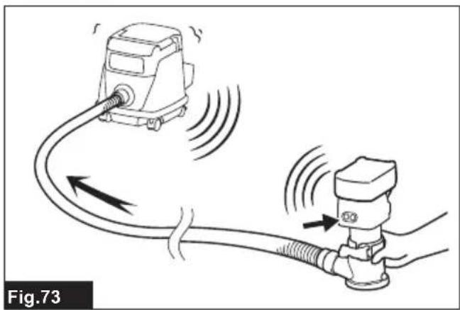
What you can do with the wireless activation function
The wireless activation function enables clean and comfortable operation. By connecting a supported vacuum cleaner to the tool, you can run the vacuum cleaner automatically along with the switch operation of the tool.
▶ Fig.73
To use the wireless activation function, prepare following items:
• A wireless unit (optional accessory)
- A vacuum cleaner which supports the wireless activation function
The overview of the wireless activation function setting is as follows. Refer to each section for detail procedures.
- Installing the wireless unit
- Tool registration for the vacuum cleaner
3. Starting the wireless activation function
Installing the wireless unit
Optional accessory
⚠️CAUTION: Place the tool on a flat and stable surface when installing the wireless unit.
NOTICE: Clean the dust and dirt on the tool before installing the wireless unit. Dust or dirt may cause malfunction if it comes into the slot of the wireless unit.
NOTICE: To prevent the malfunction caused by static, touch a static discharging material, such as a metal part of the tool, before picking up the wireless unit.
NOTICE: When installing the wireless unit, always be sure that the wireless unit is inserted in the correct direction and the lid is completely closed.
- Open the lid on the tool as shown in the figure.
▶ Fig.74: 1. Lid
- Insert the wireless unit to the slot and then close the lid.
When inserting the wireless unit, align the projections with the recessed portions on the slot.
▶ Fig.75: 1. Wireless unit 2. Projection 3. Lid 4. Recessed portion
When removing the wireless unit, open the lid slowly. The hooks on the back of the lid will lift the wireless unit as you pull up the lid.
▶ Fig.76: 1. Wireless unit 2. Hook 3. Lid
After removing the wireless unit, keep it in the supplied case or a static-free container.
NOTICE: Always use the hooks on the back of the lid when removing the wireless unit. If the hooks do not catch the wireless unit, close the lid completely and open it slowly again.
Tool registration for the vacuum cleaner
NOTE: A Makita vacuum cleaner supporting the wireless activation function is required for the tool registration.
NOTE: Finish installing the wireless unit to the tool before starting the tool registration.
NOTE: During the tool registration, do not pull the switch trigger or turn on the power switch on the vacuum cleaner.
NOTE: Refer to the instruction manual of the vacuum cleaner, too.
If you wish to activate the vacuum cleaner along with the switch operation of the tool, finish the tool registration beforehand.
- Install the batteries to the vacuum cleaner and the tool.
- Set the stand-by switch on the vacuum cleaner to "AUTO".
▶ Fig.77: 1. Stand-by switch
- Press the wireless activation button on the vacuum cleaner for 3 seconds until the wireless activation lamp blinks in green. And then press the wireless activation button on the tool in the same way.
▶ Fig.78: 1. Wireless activation button 2. Wireless activation lamp
If the vacuum cleaner and the tool are linked successfully, the wireless activation lamps will light up in green for 2 seconds and start blinking in blue.
NOTE: The wireless activation lamps finish blinking in green after 20 seconds elapsed. Press the wireless activation button on the tool while the wireless activation lamp on the cleaner is blinking. If the wireless activation lamp does not blink in green, push the wireless activation button briefly and hold it down again.
NOTE: When performing two or more tool registrations for one vacuum cleaner, finish the tool registration one by one.
Starting the wireless activation function
NOTE: Finish the tool registration for the vacuum cleaner prior to the wireless activation.
NOTE: Refer to the instruction manual of the vacuum cleaner, too.
After registering a tool to the vacuum cleaner, the vacuum cleaner will automatically run along with the switch operation of the tool.
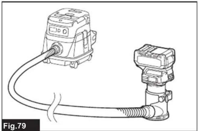
- Install the wireless unit to the tool.
- Connect the hose of the vacuum cleaner with the tool.
▶ Fig.79
3. Set the stand-by switch on the vacuum cleaner to "AUTO".
▶ Fig.80: 1. Stand-by switch
4. Push the wireless activation button on the tool briefly. The wireless activation lamp will blink in blue.
▶ Fig.81: 1. Wireless activation button 2. Wireless activation lamp
5. Turn on the tool. Check if the vacuum cleaner runs while the tool is operating.
To stop the wireless activation of the vacuum cleaner, push the wireless activation button on the tool.
NOTE: The wireless activation lamp on the tool will stop blinking in blue when there is no operation for 2 hours. In this case, set the stand-by switch on the vacuum cleaner to "AUTO" and push the wireless activation button on the tool again.
NOTE: The vacuum cleaner starts/stops with a delay. There is a time lag when the vacuum cleaner detects a switch operation of the tool.
NOTE: The transmission distance of the wireless unit may vary depending on the location and surrounding circumstances.
NOTE: When two or more tools are registered to one vacuum cleaner, the vacuum cleaner may start running even if you do not turn on your tool because another user is using the wireless activation function.
Description of the wireless activation lamp status
▶ Fig.82: 1. Wireless activation lamp
The wireless activation lamp shows the status of the wireless activation function. Refer to the table below for the meaning of the lamp status.
| Status Wireless activation lamp Description | |||||
| Standby Blue | 2 hours The wireless activation of the vacuum cleaner is available. The lamp will automatically turn off when no operation is performed for 2 hours. | ||||
| When the tool is running. | The wireless activation of the vacuum cleaner is available and the tool is running. | ||||
| Tool registration | Green | 20 seconds Ready for the tool registration. Waiting for the registration by the vacuum cleaner. | |||
| 2 seconds The tool registration has been finished. The wireless activation lamp will start blinking in blue. | |||||
| Cancelling tool registration | Red | 20 seconds Ready for the cancellation of the tool registration. Waiting for the cancellation by the vacuum cleaner. | |||
| 2 seconds The cancellation of the tool registration has been finished. The wireless activation lamp will start blinking in blue. | |||||
| Others Red | 3 seconds The power is supplied to the wireless unit and the wireless activation function is starting up. | ||||
| Off | - | - | The wireless activation of the vacuum cleaner is stopped. | ||
Cancelling tool registration for the vacuum cleaner
Perform the following procedure when cancelling the tool registration for the vacuum cleaner.
- Install the batteries to the vacuum cleaner and the tool.
- Set the stand-by switch on the vacuum cleaner to "AUTO".
▶ Fig.83: 1. Stand-by switch
- Press the wireless activation button on the vacuum cleaner for 6 seconds. The wireless activation lamp blinks in green and then become red. After that,
press the wireless activation button on the tool in the same way.
▶ Fig.84: 1. Wireless activation button 2. Wireless activation lamp
If the cancellation is performed successfully, the wireless activation lamps will light up in red for 2 seconds and start blinking in blue.
NOTE: The wireless activation lamps finish blinking in red after 20 seconds elapsed. Press the wireless activation button on the tool while the wireless activation lamp on the cleaner is blinking. If the wireless activation lamp does not blink in red, push the wireless activation button briefly and hold it down again.
Troubleshooting for wireless activation function
Before asking for repairs, conduct your own inspection first. If you find a problem that is not explained in the manual, do not attempt to dismantle the tool. Instead, ask Makita Authorized Service Centers, always using Makita replacement parts for repairs.
| State of abnormality Probable cause | (malfunction) Remedy | |
| The wireless activation lamp does not light/blink. | The wireless unit is not installed into the tool.The wireless unit is improperly installed into the tool. | Install the wireless unit correctly. |
| The terminal of the wireless unit and/or the slot is dirty. | Gently wipe off dust and dirt on the terminal of the wireless unit and clean the slot. | |
| The wireless activation button on the tool has not been pushed. | Push the wireless activation button on the tool briefly. | |
| The stand-by switch on the vacuum cleaner is not set to "AUTO". | Set the stand-by switch on the vacuum cleaner to "AUTO". | |
| No power supply Supply the power to the tool and the vacuum cleaner. | ||
| Cannot finish tool registration / cancelling tool registration successfully. | The wireless unit is not installed into the tool.The wireless unit is improperly installed into the tool. | Install the wireless unit correctly. |
| The terminal of the wireless unit and/or the slot is dirty. | Gently wipe off dust and dirt on the terminal of the wireless unit and clean the slot. | |
| The stand-by switch on the vacuum cleaner is not set to "AUTO". | Set the stand-by switch on the vacuum cleaner to "AUTO". | |
| No power supply Supply the power to the tool and the vacuum cleaner. | ||
| Incorrect operation Push the wireless activation button briefly and perform the tool registration/cancellation procedures again. | ||
| The tool and vacuum cleaner are away from each other (out of the transmission range). | Get the tool and vacuum cleaner closer to each other. The maximum transmission distance is approximately 10 m however it may vary according to the circumstances. | |
| Before finishing the tool registration/cancellation;- the switch of the tool is turned on or;- the power button on the vacuum cleaner is turned on. | Push the wireless activation button briefly and perform the tool registration/cancellation procedures again. | |
| The tool registration procedures for the tool or vacuum cleaner have not finished. | Perform the tool registration procedures for both the tool and the vacuum cleaner at the same timing. | |
| Radio disturbance by other appliances which generate high-intensity radio waves. | Keep the tool and vacuum cleaner away from the appliances such as Wi-Fi devices and microwave ovens. | |
| The vacuum cleaner does not run along with the switch operation of the tool. | The wireless unit is not installed into the tool.The wireless unit is improperly installed into the tool. | Install the wireless unit correctly. |
| The terminal of the wireless unit and/or the slot is dirty. | Gently wipe off dust and dirt on the terminal of the wireless unit and clean the slot. | |
| The wireless activation button on the tool has not been pushed. | Push the wireless activation button briefly and make sure that the wireless activation lamp is blinking in blue. | |
| The stand-by switch on the vacuum cleaner is not set to "AUTO". | Set the stand-by switch on the vacuum cleaner to "AUTO". | |
| More than 10 tools are registered to the vacuum cleaner. | Perform the tool registration again.If more than 10 tools are registered to the vacuum cleaner, the tool registered earliest will be cancelled automatically. | |
| The vacuum cleaner erased all tool registrations. | Perform the tool registration again. | |
| No power supply Supply the power to the | tool and the vacuum cleaner. | |
| The tool and vacuum cleaner are away from each other (out of the transmission range). | Get the tool and vacuum cleaner closer each other.The maximum transmission distance is approximately 10 m however it may vary according to the circumstances. | |
| Radio disturbance by other appliances which generate high-intensity radio waves. | Keep the tool and vacuum cleaner away from the appliances such as Wi-Fi devices and microwave ovens. | |
| The vacuum cleaner runs while the tool is not operating. | Other users are using the wireless activation of the vacuum cleaner with their tools. | Turn off the wireless activation button of the other tools or cancel the tool registration of the other tools. |
MAINTENANCE
⚠️CAUTION: Always be sure that the tool is switched off and the battery cartridge is removed before attempting to perform inspection or maintenance.
NOTICE: Never use gasoline, benzine, thinner, alcohol or the like. Discoloration, deformation or cracks may result.
To maintain product SAFETY and RELIABILITY, repairs, any other maintenance or adjustment should be performed by Makita Authorized or Factory Service Centers, always using Makita replacement parts.
TRIMMER BITS
Optional accessory
Straight bit
▶ Fig.85
| D A L1 L2 | |||
| 6 20 50 15 | |||
| 6 6 50 18 | |||
| 6 8 50 18 | |||
| 8 8 60 25 | |||
| 1/4" 20 50 15 |
| D A L1 L2 | |||
| 1/4" 6 50 | 18 | ||
| 1/4" 8 50 | 18 | ||
Unit:mm
U-grooving bit
▶ Fig.86
| D A L1 | L2 R | |||
| 6 | 6 | 50 | 18 | 3 |
| 1/4" | 6 | 50 | 18 | 3 |
Unit:mm
V-grooving bit
▶ Fig.87
| D A L1 | L2 | |||
| 6 | 20 | 50 | 15 | 90° |
| 1/4" | 20 | 50 | 15 | 90° |
Unit:mm
Drill point flush trimming bit
▶ Fig.88
| D A L1 | L2 L3 | |||
| 6 | 6 | 60 | 18 | 28 |
| 8 | 8 | 60 | 20 | 35 |
| 1/4" 6 | 60 18 28 | |||
Unit:mm
Drill point double flush trimming bit
▶ Fig.89
| D A L1 | L2 L3 L4 | ||||
| 6 6 70 | 40 12 14 | ||||
| 8 8 80 | 55 20 25 | ||||
| 1/4" 6 70 | 40 12 14 |
Unit:mm
Corner rounding bit
▶ Fig.90
| D A1 | A2 L1 L2 | L3 R | ||||
| 6 25 | 9 48 13 5 | 8 | ||||
| 6 20 | 8 45 10 4 | 4 | ||||
| 1/4" | 25 | 9 | 48 | 13 | 5 | 8 |
| 1/4" 20 | 8 45 10 | 4 4 |
Unit:mm
Chamfering bit
▶ Fig.91
| D A L1 L2 L3 θ | |||||
| 6 | 23 | 46 | 11 | 6 | 30° |
| 6 20 50 13 5 | 45° | ||||
| 6 | 20 | 49 | 14 | 2 | 60° |
| 1/4" | 23 | 46 | 11 | 6 | 30° |
| 1/4" | 20 | 48 | 13 | 5 | 45° |
| 1/4" | 20 | 49 | 14 | 2 | 60° |
Unit:mm
Cove beading bit
▶ Fig.92
| D | A | L1 | L2 | R |
| 6 | 20 | 43 | 8 | 4 |
| 6 | 25 | 48 | 13 | 8 |
| 1/4" | 20 | 43 | 8 | 4 |
| 1/4" | 25 | 48 | 13 | 8 |
Unit:mm
Dovetail bit
▶ Fig.93
| D | A | L1 | L2 | θ |
| 8 | 12 | 50 | 9 | 30° |
| 8 | 14.5 | 55 | 10 | 35° |
| 8 | 14.5 | 55 | 14.5 | 23° |
| 1/4" | 12 | 50 | 9 | 30° |
| 1/4" | 14.5 | 55 | 10 | 35° |
| 1/4" | 14.5 | 55 | 14.5 | 23° |
Unit:mm
Ball bearing flush trimming bit
▶ Fig.94
| D | A | L1 | L2 |
| 6 | 10 | 50 | 20 |
| 1/4" | 10 | 50 | 20 |
Unit:mm
Ball bearing beading bit
▶ Fig.95
| D | A1 | A2 | A3 | L1 | L2 | L3 | R |
| 6 | 20 | 12 | 8 | 40 | 10 | 5.5 | 4 |
| 6 | 26 | 12 | 8 | 42 | 12 | 4.5 | 7 |
| 1/4" | 20 | 12 | 8 | 40 | 10 | 5.5 | 4 |
| 1/4" | 26 | 12 | 8 | 42 | 12 | 4.5 | 7 |
Unit:mm
Ball bearing corner rounding bit
▶ Fig.96
| D A1 | A2 L1 L2 | L3 R | ||||
| 6 | 15 | 8 | 37 | 7 | 3.5 | 3 |
| 6 21 | 8 40 10 3 | 5 6 | ||||
| 1/4" | 15 | 8 | 37 | 7 | 3.5 | 3 |
| 1/4" 2' | 8 40 10 | 3.5 6 |
Unit:mm
Ball bearing chamfering bit
▶ Fig.97
| D | A1 A2 | L1 L2 θ | |||
| 6 | 26 | 8 | 42 | 12 | 45° |
| 6 | 20 | 8 | 41 | 11 | 60° |
| 1/4" | 26 | 8 | 42 | 12 | 45° |
| 1/4" | 20 | 8 | 41 | 11 | 60° |
Unit:mm
Ball bearing cove beading bit
▶ Fig.98
| D | A1 | A2 | A3 | A4 | L1 | L2 | L3 | R |
| 6 | 20 | 18 | 12 | 8 | 40 | 10 | 5.5 | 3 |
| 6 | 26 | 22 | 12 | 8 | 42 | 12 | 5 | 5 |
| 1/4" | 20 | 18 | 12 | 8 | 40 | 10 | 5.5 | 3 |
| 1/4" | 26 | 22 | 12 | 8 | 42 | 12 | 5 | 5 |
Unit:mm
Ball bearing roman ogee bit
▶ Fig.99
| D | A1 | A2 | L1 | L2 | L3 | R1 | R2 |
| 6 | 20 | 8 | 40 | 10 | 4.5 | 2.5 | 4.5 |
| 6 | 26 | 8 | 42 | 12 | 4.5 | 3 | 6 |
| 1/4" | 20 | 8 | 40 | 10 | 4.5 | 2.5 | 4.5 |
| D A1 A2 | L1 L2 | L3 R1 | R2 | ||||
| 1/4" 26 8 | 42 12 | 4.5 3 6 |
Unit:mm
OPTIONAL ACCESSORIES
⚠️CAUTION: These accessories or attachments are recommended for use with your Makita tool specified in this manual. The use of any other accessories or attachments might present a risk of injury to persons. Only use accessory or attachment for its stated purpose.
If you need any assistance for more details regarding these accessories, ask your local Makita Service Center.
- Straight and groove forming bits
- Edge forming bits
- Laminate trimming bits
- Straight guide assembly
- Trimmer guide assembly
- Trimmer base assembly
- Trimmer base assembly (resin)
- Tilt base assembly
- Plunge base assembly
- Offset base assembly
- Grip attachment
- Templet guide
- Collet cone
- Wrench 13
- Wrench 22
- Wireless unit
- Makita genuine battery and charger
NOTE: Some items in the list may be included in the tool package as standard accessories. They may differ from country to country.
Accessories applicable to this trimmer
The tool can be used with the following accessories for a variety of purposes.
Some accessories are not available in your country.
▶ Fig.100
-
Trimmer base (metal)
-
Trimmer base (resin) Clear visibility of the cut.
-
Tilt base
-
Offset base
-
Plunge base
-
Grip attachment
-
Templet guide
-
Straight guide
-
Trimmer guide
-
Trimmer shoe Enables accurate edge works. *Use with parts of the trimmer guide.
-
Dust nozzle
-
Base plate (metal)
-
Square base plate (base plate of the tilt base)
-
Offset base plate (base plate of the offset base) By using the offset base plate with the grip attachment, grip can be attached.
-
Base plate (resin)
-
Grip base
-
Bar type grip
-
Knob type grip (grip of the plunge base)
-
Dust nozzle for the plunge base
-
Templet guide for the plunge base
-
Guide holder This allows the straight guide for the trimmer base to be used on the plunge base.
-
Parallel ruler Fine adjustment function of positioning.
-
Parallel ruler
-
Guide rail adapter
-
Guide rail
For accurate straight cutting.
-
Bevel guide For angle adjustment of the guide rail.
-
Guide rail joint connector (2 pcs.) For jointing two guide rails.
-
Clamp (standard type) For fixation of the guide rail.
-
Clamp (quick type) For fixation of the guide rail.
-
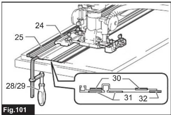
Seat Repair parts of the guide rail for upper plastic tape.
-
Rubber seat Repair parts of the guide rail for lower rubber tape.
-
Position seat Repair parts of the guide rail for position seat.
▶ Fig.101
SPÉCIFICATIONS
▶ Fig.18: 1. Plaque du socle
▶ Fig.22: 1. Plaque du socle
▶ Fig.25: 1. Poulie 2. Courroie
▶ Fig.31: 1. Écrou hexagonal
▶ Fig.49: 1. Orifice central
▶ Fig.50: 1. Orifice central
▶ Fig.51: 1. Clou 2. Orifice central
VEILIGHEIDSWAAR- SCHUWINGEN
▶ Fig.11: 1. Vingermoer 2. Tandheugel 3. Tandwiel
▶ Fig.63: 1. Rechte handgreep
- Handgreep-hulpstuk
▶ Fig.64: 1. Schroef 2. Knophandgreep
Ojiefbit met kogellager
▶ Fig.99
OPTIONELE ACCESSOIRES
▶ Fig.31: 1. Tuerca hexagonal
▶ Fig.31: 1. Porca hexagonal