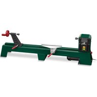
PDB 100 A1 - Wood lathe PARKSIDE - Free user manual and instructions
Find the device manual for free PDB 100 A1 PARKSIDE in PDF.

| Product type | Wood lathe |
| Brand | Parkside |
| Model | PDB 100 A1 |
| Rated voltage | 230-240 V~, 50 Hz |
| Rated power consumption | 400 W |
| No-load speed | 890/1260/1760/2600 min-1 |
| Operation mode | S2 15 min (intermittent) |
| Protection type | IPX0 |
| Spindle thread | M18 |
| Weight (with accessories) | approx. 20.5 kg |
| Max workpiece length | 1000 mm |
| Max workpiece diameter | 350 mm |
| Sound pressure level | 71 dB(A) |
| Sound power level | 84 dB(A) |
| Included accessories | 4-prong drive center, screw chuck, tailstock, tool rest, 2 chisels (straight and gouge), 2 open-end wrenches, hex key, screws |
| Speed adjustment | By V-belt, 4 speeds |
| Safety | Locking switch on covers, on/off switch |
| Warranty | 3 years |
| Cleaning | Brush or cloth, no water jet |
| Intended use | Private use, wood turning |
Frequently Asked Questions - PDB 100 A1 PARKSIDE
User questions about PDB 100 A1 PARKSIDE
0 question about this device. Answer the ones you know or ask your own.
Ask a new question about this device
Download the instructions for your Wood lathe in PDF format for free! Find your manual PDB 100 A1 - PARKSIDE and take your electronic device back in hand. On this page are published all the documents necessary for the use of your device. PDB 100 A1 by PARKSIDE.
USER MANUAL PDB 100 A1 PARKSIDE
Translation of the original instructions
NL BE
Draabank
Before reading, unfold the page containing the illustrations and familiarise yourself with all functions of the device.
FR BE
GB/IE Translation of the original instructions Page 17
n.890/1260/1760/2600 min
DE AT CH
Schutzklasse
Schutzart.. IPX0
Spindelkopfgewinde...M18
Scope of delivery. 18
Overview. 18
Description of functions. 18
Technical data. 18
Safety information 19
Graphical symbols 19
Safe working 20
Safety instructions for working with the lathe 21
Assembly instructions. 21
Assembling the lathe 21
Setting up the lathe 22
Installing/changing the workpiece mounts. 22
Operation 22
Selecting the speed 22
Securing the workpiece. 23
Adjusting the tool table 24
Switching on/off 24
Working instructions 24
Remove blockages 25
Cleaning/maintenance. 25
General cleaning and maintenance work. 25
Storage. 25
Transport 25
Disposal / Environmental
protection 25
Spare parts/accessories. 26
Troubleshooting 26
Guarantee 27
Repair Service. 28
Service-Center 28
Importer 28
Translation of the original EC declaration of conformity. 99
Exploded Drawing 105
Introduction
Congratulations on the purchase of your new device. With it, you have chosen a high quality product.
During production, this equipment has been checked for quality and subjected to a final inspection. The functionality of your equipment is therefore guaranteed.
The operating instructions constitute part of this product. They contain important information on safety, use and disposal.
Before using the product, familiarise yourself with all of the operating and safety instructions. Use the product only as described and for the applications specified.
Keep this manual safely and in the event that the product is passed on, hand over all documents to the third party.
Proper use
The lathe is intended for processing wood using a suitable turning tool.
Any other use not expressly approved in the present instruction manual can damage the device and thus present a substantial risk for the user.
The device is intended to be used by do-it-yourselfers. It was not designed for heavy commercial use. The warranty is void in the case of commercial use.
The device is intended for use by adults.
Children and people who are not familiar with these instructions must not use the device. The use of the device in the rain or a damp environment is prohibited. The manufacturer is not liable for damage caused by improper use or incorrect operation.
General description

An illustration of the most important functional components can be found on the front and the back fold-out pages.
Scope of delivery
Carefully remove the device from the packaging and check whether all the parts listed below are present and complete:
Woodturning Lathe (two-part)
- Face plate
Tailstock
- Tool table (two-part)
- 2 lathe chisel (1x straight, 1x hollow)
- 2 × open-ended spanners
- Allen key
- Mounting material:
- 6 hexagon bolts, 6 clamping disks, 6 washers, 6 nuts
-
3 screws, 3 clamping disks, 3 washers
-
Instruction manual
Dispose of the packaging material properly.
Overview

1 4-edge lathe point
2 Tool table
2.1 Screw, height adjustment
2.2 Bottom part of tool table
3.1 Rail with motor unit
3.2 Rail
4 Locknut
5 Tailstock
6 Handwheel
7 Foot
8 Lever, tailstock
9 Lever, tool table
10 On switch
11 Off switch
12 Allen key
13 Face plate
14 Lathe chisel, straight
15 Lathe chisel, hollow
16 Open-ended spanner
17 Screws with clamping disk and washer
18 Hexagon bolts with clamping disk, washer and nut

19 Drive shaft

20 Locking screw

Gear cover
22 Retaining screw
23 Motor unit
24 Lever, motor unit
25 Drive pulley 26 V-belt
27 Locking switch
Description of functions
The lathe is intended for processing pieces of wood. The clamped workpieces can be rotated at three different speeds.
Please refer to the descriptions below for information on how the operating elements work.
Technical data
Woodturning Lathe .... PDB 100 A1
Rated voltage U 230-240 V\~ Rated frequency .50 Hz
Rated consumption P 400 W
Operating mode..S2 15 min*
Idle speed
n_0 890/1260/1760/2600 min-1
Protection class
Protection type . IPX0
Spindle head thread.. M18
Weight (with accessories, complete) approx. 20,5 kg Max.workpiece length 1000 mm Max.workpiece diameter .350 mm Sound pressure level (L_pA) .71 dB(A); K_pA = 3dB Sound power level (L_WA) measured .84 dB(A); K_WA = 3dB
- After continuous operation of 15 minutes the device stops until the device temperature deviates by less than 2K (2^) from the room temperature.
Levels of noise were determined according to the norms and regulations in the declaration of conformity.
Safety information
CAUTION! The following basic safety precautions must be observed while using electric tools to protect against electric shock, injury and risk of fire. Please read all instructions before using this electric tool and keep the safety instructions in a safe place.
This section describes the basic safety rules when working with the device.
Graphical symbols
Symbols on the device:

Caution!

Read the instruction manual carefully.

Caution! If the mains connection cable is damaged or cut through, immediately pull the plug from the socket.

Wear eye protection.

Wear ear protection.

Wear respiratory protection.

Do not use as a step.

Do not wear long hair uncovered. Use a hair net.

Do not expose the device to moisture.

M18
Thread socket

Direction of spindle rotation

100 86
Speed settings

Table for selecting the speed

Electrical devices must not be disposed of with domestic waste.
Symbols used in the instruction manual:

Hazard symbol with information on the prevention of personal injury or property damage.

Hazard symbol with information on damage prevention.

Pull out the mains plug.

Advisory symbol with information on how to best use the device.
Safe working
1 Keep your work area tidy
- An untidy workplace can lead to accidents.
2 Consider environment influences
-
Do not expose power tools to rain.
-
Do not use power tools in damp or wet surroundings.
-
Ensure the work area is adequately lit.
-
Do not use power tools where there is a fire or explosion hazard.
3 Protect yourself against electric shock
- Avoid body contact with earthed parts
(e.g. pipes, radiators, electric cookers, refrigerators).
4 Keep other people away!
- Do not allow other people, especially children, to touch the power tool or cable, and keep them away from your work area.
5 Store unused power tools safely
- Unused power tools should be stored in a dry, high or locked place, out of the reach of children.
6 Do not overload your power tool
- They work better and more safely within the specified power range.
7 Use the correct power tool
-
Do not use low-performance electric tools for heavy work.
-
Do not use the power tool for purposes for which it is not intended. For example, do not use a circular hand saw for cutting tree branches or logs
8 Wear suitable clothing
-
Do not wear loose clothing or jewellery that might become caught in moving parts.
-
When working outdoors, non-slip footwear is recommended.
-
Wear a hair net to contain long hair.
9 Use protective equipment
Wear safety goggles.
- Use a dust mask for work which generates dust.
10 Connect a dust extraction device
- If connections are available for dust extraction and collection devices, make sure that these are connected and properly used.
11 Do not use the cable for purposes for which it is not intended
- Do not use the cable to pull the plug from the socket. Protect the cable from heat, oil and sharp edges.
12 Secure the workpiece
- Use jigs or a vice to hold the workpiece securely. This is safer than using your hand.
13 Avoid abnormal body postures
- Ensure secure footing and keep your balance at all times.
14 Maintain tools with care
-
Keep cutting tools sharp and clean for better and safer working.
-
Follow the instructions for lubrication and changing tools.
-
Regularly check the connection cable of the power tool and, if it is damaged, have it replaced by a qualified specialist.
-
Check extension cords periodically and replace them if they are damaged.
-
Keep handles dry, clean and free from oil and grease.
15 Remove the plug from the mains socket
- When the electric tool is not in use, before maintenance and when changing tools such as the saw blade, drill bit, milling cutter.
16 Do not allow any tool keys to remain inserted
- Check, before switching on, that keys and adjusting tools have been removed.
17 Avoid unintentional starting
- Make sure that the switch is off when inserting the plug into the socket.
18 Use extension cables outdoors
-Only use approved and appropriately marked extension cables outdoors.
19 Pay attention at all times
- Pay attention to what you are doing. Work using common sense. Do not use the power tool if you cannot concentrate.
20 Check the power tool for possible damage
Before further use of the power tool, safety devices or slightly damaged parts must be carefully examined in respect of their proper and intended function.
-
Check whether the moving parts are working properly and are not becoming jammed or whether parts are damaged. All parts must be correctly fitted and satisfy all conditions to ensure the proper operation of the power tool.
-
Damaged safety equipment and parts must be repaired properly or replaced by an authorised specialist workshop unless otherwise indicated in the operating instructions.
-
Damaged switches must be replaced at a customer service workshop.
-
Do not use power tools if the switch cannot be turned on and off.
21. CAUTION!
The use of other bits and other accessories can result in a risk of personal injury.
22 Have your power tool be repaired by a qualified electrician
- This power tool complies with the relevant safety regulations. Repairs may
only be performed by a qualified electrician, using original spare parts; otherwise accidents involving the user may result.
Safety instructions for working with the lathe
- When lathing, use a suitable external extraction system to prevent damage to your health.
Clean the lathe and work station immediately after working to prevent dust from spreading and slip hazards. - Secure the workpiece between the tailstock and the 4-edge lathe centre without applying too much pressure.
Excessive clamping pressure can deform the workpiece and cause it to come out of the clamp when rotating.
Excessive clamping pressure can cause motor start-up problems.
Only use original lathe chisels. Only work with sharp lathe chisels.
- Place the lathe on a solid surface (e.g. a work bench) and connect the lathe to the surface.
- Keep hands away from the rotating workpiece.
- When selecting the workpiece, pay attention to branches, knots or cracks; they are at a risk of bursting.
Use wood without cracks, knots or large branches.
Assembly instructions
B Assembling the lathe
- Slide the tool table (2) onto the rail with motor unit (3.1).
- Slide the tailstock (5) for the tool table (2) onto the rail with motor unit (3.1).
GB E
Pull up to check whether the tailstock (5) and the tool table (2) have been inserted correctly.
- Connect the rail with motor unit (3.1) and the rail (3.2) without motor unit.
- Join the two rails using the three screws with clamping disk and washer (17).

If it is difficult to move the tool table (2) or the tailstock (5), re-adjust the washer on the bottom side using an open-ended spanner or a ratchet (AF 19).

Setting up the lathe
- Place the lathe on a solid surface.
- Bolt the lathe to the surface. Use the two holes in the three feet (7).
- You can use the supplied hexagon bolts (18) for this.
- Place the washer and the clamping disk on the hexagon bolt (18). See illustration A.
- Bolt the lathe to the surface using the hexagon bolt, washer, clamping disk and nut (18).

Installing/changing the workpiece mounts

Switch off the device and unplug the mains plug.
Mounting the 4-edge lathe centre
- If necessary, loosen the face plate (13). Hold the drive shaft (19) using the open-end spanner (16) and remove the face plate (13) from the drive shaft (19).
-
Hold the drive shaft (19) with the open-end spanner (16).
-
Tighten the 4-edge lathe centre (1) onto the drive shaft using a second open-end spanner (16).
For lathing e.g. bowls or pots, you have to use the face plate (13) instead of the 4-edge lathe centre point (1).
Mounting the face plate
- If necessary, loosen the 4-edge lathe centre (1). Place the two open-end spanners (16) on the drive shaft (19) and the 4-edge lathe centre (1), then remove the 4-edge lathe centre (1).
- Hold the drive shaft (19) with the open-end spanner (16).
- Tighten the face plate (13) onto the drive shaft (19).
Operation

Selecting the speed

The mains plug must not be plugged in when adjusting the speed.
Selecting the right speed:
- First, select a low speed for new workpieces.
Increase the speed the bigger the workpiece.
- The right speed depends on multiple factors, such as the material, diameter, length and size. Generally:
For harder woods, workpieces that are not round, long workpieces with a large diameter, choose a low speed.
- When choosing the speed, use the following table as a guide:
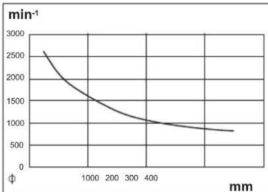
The workpiece diameter is indicated on the X-axis. The Y-axis represents the speed. Start with the diameter of the workpiece and follow it upwards vertically, then read the speed where the vertical line meets the curve.
- Loosen the two locking screws (20) on the two gear covers (21).
- Open the gear covers (21).
- Loosen the retaining screw (22) on the motor unit using the Allen key (12).
- Using the lever (24), lift the motor unit (23) to release the load on the V-belts (26).
- Tighten the retaining screw (22) on the motor unit (23).
- Place the V-belt (26) on the desired notch on the drive pulley (25) to reach the specified speed:

The V-belt must be on the same notch of both the upper and lower drive pulley.

The two gear covers (21) are equipped with a locking switch (27). The locking switches (27) are automatically actuated when closing the gear covers (21). If the gear cover (21) is not closed correctly, the device cannot be switched on.
- Loosen the retaining screw (22) and lower the lever with the motor unit to clamp the V-belt.
- Tighten the retaining screw (22).
- Close the gear covers (21). Attach the gear covers with the locking screws (20).
Securing the workpiece

Secure with 4-edge lathe centre (1) and tailstock (5)
1 Draw a diagonal line on both ends of the workpiece to locate the centre. The centre is the place where the two lines meet. Place a centring hole where the 4-edge lathe and tailstock should be positioned on the workpiece. This ensures a better hold.
2. Cut an approx. 2mm deep saw cut along the diagonals to give the 4-edge lathe centre (1) a better grip.
3. Place the removed 4-edge lathe centre (1) at the centre of the workpiece. Lightly tap the 4-edge lathe centre (1) into the workpiece using a mallet (not included in the scope of delivery). Make sure to protect the thread of the 4-edge lathe centre (1) e.g. with a wooden board.
4. Remove the 4-edge lathe centre (1) from the workpiece.
5. Next, (re)attach the 4-edge lathe centre (1) to the device.

Refer to the section "Installing/ changing the workpiece mounts" for more on how to assemble and disassemble the 4-edge lathe centre.
- Place the workpiece on the 4-edge lathe centre (1).
Make sure to meet the notch with the 4-edge lathe centre (1) as otherwise secure clamping cannot be ensured.
GB E
- Open the lever (8) of the tailstock.
- Slide the tailstock towards the 4-edge lathe centre (1) almost up to the workpiece to clamp it.
- Fix the tailstock by pressing the lever (8) downwards.
- For fine adjustment, use the handwheel (6).
- Fix the position of the handwheel using the locknut (4).
D
Securing with the face plate (13)
- Hold the drive shaft (19) with the open-end spanner (16).
- Remove the face plate (13) from the drive shaft (19).
- Fix the workpiece to the face plate (13) using wood screws (not included in the scope of delivery).
!
Risk of injury! The wood screws must be placed so that you do not accidentally expose them using the tool when processing the workpiece.
-
Hold the drive shaft (19) with the open-end spanner (16).
-
Tighten the face plate (13) with mounted workpiece onto the drive shaft (19).
A
Adjusting the tool table
!
Risk of injury! Make sure the tool table is fixed properly and is unable to come loose during operation.
Fixing/loosening the tool table
-
The tool table (2) is fixed by pressing the lever (9) downwards.
-
The tool table (2) is loosened by pressing the lever (9) upwards. You can now move the tool table.
Tool table height adjustment
- Loosen the screw (2.1) on the bottom part of the tool table (2.2).
- Set the desired height.
- Fix the tool table (2) by tightening the screw (2.1).
A
Switching on/off
- Connect the device to the mains voltage supply.
Switching on:
- To start the device, press the on/off switch (10).
Switching off:
- To stop the device, press the off switch (11).
#
Pull out the mains plug if you are leaving the device unattended or if you have finished working.
Working instructions
- Read sufficient specialised literature before beginning to work.
- When selecting the workpiece, pay attention to branches, knots, cracks etc. You could lose control of the tool, which can result in serious injuries.
Cracked workpieces can burst during turning. Risk of injury! - Before processing, cut the workpiece into form as much as possible.
-
Pay attention to the maximum workpiece length and maximum workpiece diameter! You will find them in the technical data.
The workpiece must be fixed at the centre; workpieces that run uneven have an effect on the machine service life. -
Only use tools suitable for turning.
- Never stand in the flight path of the workpiece.
- Before beginning your work, make sure the mains plug is unplugged then check the following by turning manually:
- Is the workpiece fixed?
- Does the workpiece come into contact with the tool table?
Always begin with a low speed, increasing gradually. - Do not introduce the tool to the workpiece until it has reached the set speed.
Remove blockages

Switch off the device and unplug the mains plug.
Clean any dust and chips from the device to remove any blockages.
Cleaning/maintenance

Have any work that is not described in these instructions performed by an authorised customer service centre. Only use original parts.

Before any maintenance or cleaning work, turn off the machine, unplug the mains plug and wait for the workpiece to come to a standstill. There is a risk of personal injury
General cleaning and maintenance work

Never spray down the device with water. There is a risk of electric shock.
Always keep the device clean. Use a brush or cloth for cleaning, but do not use any cleaning agents or solvents.
- Check the covers and protective devices for damage and correct fit. Replace these if necessary.
- Every 10 hours of operation, check the V-belt for wear or any damage.
Storage
Store the device in a dry and dustproof location and out of reach of children.
Transport

Switch off the device and unplug the mains plug. There is a risk of injury.

Caution! Hot surface. There is a risk of burns. Only transport the machine when the motor unit (E 23) has cooled down completely.
If possible, carry the lathe together with another person.
When transporting the lathe, grab it at the external feet (A 7), the rail with motor unit (A 3.1) and the rail (3.2).
Disposal /
Environmental protection
The device, accessories and packaging should be properly recycled.

Electrical devices must not be disposed of with domestic waste.
- Take the device to a recycling plant. The plastic and metal parts used on your device can be properly sorted
according to materials and grades and efficiently recycled. Please contact our service centre for more information.
We will dispose of any defective devices that you send to us free of charge.
Spare parts/accessories
You can get spare parts and accessories from www.grizzly-service.eu
If you have issues ordering, please use the contact form. If you have any other questions, contact the service centre (see page 28).
| Position instruction manual | Position exploded drawing | Name | Order no. | |
| E 21 | 16,18,19 | Gear | cover | |
| E 21 | 16,18,19 | Gear | cover | |
| 83-86 | —— | Tool set | ||
| A 12 | Allen key | |||
| A 13 | 83 | Face plate | ||
| A 14/15 | 86 Lathe chisel | |||
| A 16 | 85 Open-ended spanner | 91095912 | ||
| 34 Tailstock centre | 91095913 | |||
| E 26 | 48 | V-belt | 91095914 | |
Troubleshooting
| Problem | Possible cause | Troubleshooting |
| Lathe does not rotate | Not connected to mains | Plug in the power plug |
| Drive cover(s) (E 21) not connected properly | Properly connect drive cover(s) so the lock switch (E 27) is actuated | |
| Bad cutting quality | Improper rotating speed | Set speed (see “Selecting the speed”) |
| Tool blunt | Sharpen/replace tool | |
| Excessive vibrations | Workpiece not correctly clamped | Make sure the workpiece is sitting correctly (see “Securing the workpiece”) |
| Workpiece unbalanced | Cut workpiece until balanced |
Guarantee
Dear Customer,
This equipment is provided with a 3-year guarantee from the date of purchase.
In case of defects, you have statutory rights against the seller of the product. These statutory rights are not restricted by our guarantee presented below.
Terms of Guarantee
The term of the guarantee begins on the date of purchase. Please retain the original receipt. This document is required as proof of purchase.
If a material or manufacturing defect occurs within three years of the date of purchase of this product, we will repair or replace - at our choice - the product for you free of charge. This guarantee requires the defective equipment and proof of purchase to be presented within the three-year period with a brief written description of what constitutes the defect and when it occurred.
If the defect is covered by our guarantee, you will receive either the repaired product or a new product. No new guarantee period begins on repair or replacement of the product.
Guarantee Period and Statutory Claims for Defects
The guarantee period is not extended by the guarantee service. This also applies for replaced or repaired parts. Any damages and defects already present at the time of purchase must be reported immediately after unpacking. Repairs arising after expiry of the guarantee period are chargeable.
Guarantee Cover
The equipment has been carefully produced in accordance with strict quality
guidelines and conscientiously checked prior to delivery.
The guarantee applies for all material and manufacturing defects. This guarantee does not extend to cover product parts that are subject to normal wear and may therefore be considered as wearing parts (e.g. 4-edge lathe point, V-belt, Lathe chisel) or to cover damage to breakable parts (e.g. switches).
This guarantee shall be invalid if the product has been damaged, used incorrectly or not maintained. Precise adherence to all of the instructions specified in the operating manual is required for proper use of the product. Intended uses and actions against which the operating manual advises or warns must be categorically avoided.
The product is designed only for private and not commercial use. The guarantee will be invalidated in case of misuse or improper handling, use of force, or interventions not undertaken by our authorised service branch.
Processing in Case of Guarantee
To ensure quick handling of you issue, please follow the following directions:
-
Please have the receipt and identification number (IAN 339397_1910) ready as proof of purchase for all enquiries.
-
Please find the item number on the rating plate.
-
Should functional errors or other defects occur, please initially contact the service department specified below by telephone or by e-mail. You will then receive further information on the processing of your complaint.
After consultation with our customer service, a product recorded as defective can be sent postage paid to the
service address communicated to you, with the proof of purchase (receipt) and specification of what constitutes the defect and when it occurred. In order to avoid acceptance problems and additional costs, please be sure to use only the address communicated to you. Ensure that the consignment is not sent carriage forward or by bulky goods, express or other special freight. Please send the equipment inc. all accessories supplied at the time of purchase and ensure adequate, safe transport packaging.
Repair Service
For a charge, repairs not covered by the guarantee can be carried out by our service branch, which will be happy to issue a cost estimate for you.
We can handle only equipment that has been sent with adequate packaging and postage.
Attention: Please send your equipment to our service branch in clean condition and with an indication of the defect.
Equipment sent carriage forward or by bulky goods, express or other special freight will not be accepted.
We will dispose of your defective devices free of charge when you send them to us.
Service-Center
GB Service Great Britain Tel.: 0800 404 7657
E-Mail: grizzly@lidl.co.uk
IAN 339397_1910
IE Service Ireland
Tel.: 1890 930 034
(0,08 EUR/Min., (peak))
(0,06 EUR/Min., (off peak))
E-Mail: grizzlyy@lidl.ie
IAN 339397_1910
Importer
Please note that the following address is not a service address. Please initially contact the service centre specified above.
Chere cliente, cher client,
n_0 890/1260/1760/2600 min-1
Elektrische veiligheidsklasse.
Beschermingsgraad .IPX0
n_0 890/1260/1760/2600 min-1
Trieda ochrany.
Druh ochrany.. IPX0
Zavith hlavy vretena.. M18
Hmotnost's prisluesenstvom,
kompletná) cca 20,5 kg
Max.dizka obrobku 1000 mm Max.priemer obrobku 350 mm Hladina akustickeho tlaku (LpA) .71 dB(A); KpA = 3 dB Hladina akustickeho vykonu (LWA) odmerana.84 dB(A); KWA = 3 dB
- Po nepretržitej prevaldze poças 15 minuti nasleduje prestavka, kym Rozdiel teploty pristroja a teploty okolia nie je mensi ako 2 K (2 °C).
| Translation of the original EC declaration of conformity | |
| We hereby confirm that the Woodturning Lathe PDB 100 A1 series Serial number 202003000001 - 202003010850 conforms with the following applicable relevant version of the EU guidelines: | |
| 2006/42/EC • 2014/30/EU • 2011/65/EU* | |
| In order to guarantee consistency, the following harmonised standards as well as national standards and stipulations have been applied: | |
| EN 61029-1:2009/A11:2010 • EN ISO 12100:2010 EN 55014-1:2017 • EN 55014-2:2015 EN 61000-3-2:2014 • EN 61000-3-3:2013 • EN 62321-1:2013 | |
| This declaration of conformity is issued under the sole responsibility of the manufacturer: | |
| CE Grizzly Tools GmbH & Co. KG Stockstädter Straße 20 63762 Großbostheim Germany 30.03.2020 | Christian Frank Documentation Representative |
- The object of the declaration described above satisfies the provisions of Directive 2011/65/EU of the European Parliament and the Council of 8 June 2011 on limiting the use of certain harmful substances in electrical and electronic appliances.
FR
BE