
TKC9511EG - Surveillance Camera JVC - Free user manual and instructions
Find the device manual for free TKC9511EG JVC in PDF.

| Product type | Color surveillance camera |
| Brand | JVC |
| Model | TKC9511EG |
| Sensor | 1/2 inch CCD |
| Horizontal resolution | 550 TV lines (typical) |
| Minimum illumination (color) | 0.025 lx (25%, F1.2, AGC HIGH) |
| Minimum illumination (black and white) | 0.003 lx (25%, F1.2, AGC HIGH) |
| Signal-to-noise ratio | 52 dB (typical, AGC OFF) |
| Lens mount | CS (C adapter available) |
| Power supply | 220-240 V AC, 50/60 Hz |
| Power consumption | 60 mA |
| Weight | 490 g |
| Operating temperature | -10°C to 50°C |
| Day/night functions | Automatic (color / black and white) |
| 3D noise reduction (DNR) | Yes |
| Electronic Sens Up | Up to 128x |
| Communication | RS-485, Pelco-D and Pelco-P protocols |
| Motion detection | Yes, with 48 adjustable zones |
| Privacy mask | Up to 4 zones |
| Scene files | 8 presets (GENERAL, TRAFFIC, etc.) |
| Maintenance | Clean with a soft, dry cloth; do not use benzene or thinner |
| Included accessories | Instruction manual, CD-ROM |
| Safety | Do not open the case; professional installation recommended |
Frequently Asked Questions - TKC9511EG JVC
User questions about TKC9511EG JVC
0 question about this device. Answer the ones you know or ask your own.
Ask a new question about this device
Download the instructions for your Surveillance Camera in PDF format for free! Find your manual TKC9511EG - JVC and take your electronic device back in hand. On this page are published all the documents necessary for the use of your device. TKC9511EG by JVC.
USER MANUAL TKC9511EG JVC
MANUEL D'INSTRUCTIONS
TO REDUCE THE RISK OF FIRE OR ELECTRIC SHOCK, DO NOT EXPOSE THIS APPLIANCE TO RAIN OR MOISTURE.
AVENTISSEMENT
POUR EVITER LES RISQUES D'INCENDIE OU D'ELECTRO-CUTION, NE PAS EXPOSER L'APPAREIL A L'HUMIDITE OU A LA PLUIE.
POWER SYSTEM (TK-C9511EG only)
Connection to the mains supply
This unit operates on voltage of 220 V to 240 V AC, 50 Hz/60 Hz.
CAUTION
To prevent electric shock, do not open the cabinet. No user serviceable parts inside. Refer servicing to qualified service personnel.
Dear Customer
This apparatus is in conformance with the valid European directives and standards regarding electromagnetic compatibility and electrical safety.
European representative of Victor Company of Japan, Limited is: JVC Technical Services Europe GmbH
Postfach 10 05 04
61145 Friedberg
Germany
Information for Users on Disposal of Old Equipment [European Union]
![JVC TKC9511EG - Information for Users on Disposal of Old Equipment [European Union] - 1](/content/2026/03/516796/images/0a2665a7e8b8abec0ee5745b2343367e562a966490e9d8fc9a3cd03166a99e11.jpg)
Attention:
This symbol is only valid in the European Union.
This symbol indicates that the electrical and electronic equipment should not be disposed as general household waste at its end-of-life. Instead, the product should be handed over to the applicable collection point for the recycling of electrical and electronic equipment for proper treatment, recovery and recycling in accordance with your national legislation.
By disposing of this product correctly, you will help to conserve natural resources and will help prevent potential negative effects on the environment and human health which could otherwise be caused by inappropriate waste handling of this product. For more information about collection point and recycling of this product, please contact your local municipal office, your household waste disposal service or the shop where you purchased the product. Penalties may be applicable for incorrect disposal of this waste, in accordance with national legislation.
(Business users)
If you wish to dispose of this product, please visit our web page http://www.jvc.eu to obtain information about the take-back of the product.
[Other Countries outside the European Union]
If you wish to dispose of this product, please do so in accordance with applicable national legislation or other rules in your country for the treatment of old electrical and electronic equipment.
- The unit is to be powered by an AC 24 V or a DC 12 V power supply. (TK-C9510E only)
- The AC 24 V and 12 V DC power supply shall conform to the following: Isolated power supply only. (TK-C9510E only)
- This installation should be made by a qualified service person and should conform to all local codes.
- This installation shall be in accordance with the National Electrical Code, ANSI/NFPA 70.
- Any Mention in this manual of Alarm inputs have not been evaluated by UL to be used for Burglar Alarm Functionality.
- Special technique is required when installing this product. Please refer to your dealer for installation.
Rating label is pasted on the camera unit. - JVC is not liable for any compensation if you drop the camera due to insecure mounting by not following the installation description. Pay careful attention during installation.
-
When mounting this product to a ceiling or wall, select a location strong enough to support the weight, be sure to reinforce the ceiling or wall before installation.
-
The camera may drop if the mounting screws are not tightened securely. Check that the screws are tightened appropriately and securely.
- Do not install the camera near lighting fixtures of high temperature, such as spot lights. It might result in failure or fires.
Features
C
Realizes stable image quality
Effective for shooting at dimly-lit places
Supports Pelco-D and Pelco-P protocols
This camera employs a 1/2-inch CCD, which realizes colour with a minimum illumination of 0.025 lx (F1.2, 25% ). page 71
- Equipped with a wide dynamic range. Corrects dark and white regions due to drastic brightness differences in the subject. Realizes a clear and stable image quality.
page 38
- Equipped with a DAY/NIGHT feature for 24-hour surveillance in colour in the day and in black-and-white at night.
page 42
- Equipped with a three-dimensional DNR feature that significantly improves the image quality in low-light conditions. Realizes noise-free, clear and vivid images.
page 45
- Equipped with an Electronic Sense Up feature that corrects the brightness to reproduce clear images at night or dark environment. The sensitivity level can be increased up to x128.
page 37
- Equipped with an RS-485 terminal for communication, which supports Pelco-D and Pelco-P protocols.
page 49
Supports registration of scene files for different environments
Eight scene files are available. Each scene file has preset settings for different applications. They can also be customized. page 35
Detects suspicious movements inside setting area
Changes in scene such as movement inside the set area are automatically detected, and an alarm display or signal can be output. page 47
Hides specific areas and protects privacy
- Up to four locations on the shooting screen can be hidden.
- page 65
Contents
Introduction
Features 6
Contents 8
How to Read This Manual 10
Operating Precautions 11
Names of Parts 14
Connection/Installation
Quick Installation 16
System Connection 18
Mounting the Lens 20
Connection 21
Mounting the Camera 24
Setting/Adjustment
Switch Settings 26
Adjusting the Back Focus 28
Fine-tuning the Focus 30
Adjusting the Auto White Balance 31
Menu Settings
Menu Screen Flow 32
Menu Setting 34
SCENEFILE 35
BASIC SETTINGS 36
VIDEO SETTINGS 44
VIDEO EFFECT 46
MOTION DETECT 47
MAINTENANCE 49
PRIVACY MASK 51
AUX FUNCTION 52
Detailed Settings
Default Values of Scene Files 54
Motion Detect Area Setting 56
Scene Name/Camera Title Setting 58
Manual White Balance Adjustment 60
Output of Black-and-white/Colour Switch Signal 61
Controlling Black-and-white/Colour Switch Signal Externally 63
Privacy Mask Setting 65
BLC Photometry Area Setting 66
Others
Troubleshooting 67
Index 70
Specifications 71
Thank you for purchasing this product.
Before use, please read this "INSTRUCTIONS" and the information materials included to ensure proper use of this product.
The instructions in this manual are for TK-C9510E/TK-C9511EG.
How to Read This Manual
| How to Read This Manual |
| Conventions and symbols |
| Note : Indicates operating precautions. |
| Memo : Indicates reference data regarding limitations on functions, usage and the like. |
| : Indicates a reference page or item. |
| Contents of this manual |
| ·JVC holds the copyright to this manual. Any part or all of this manual may not be reproduced without prior consent from the company. |
| ·Product names of other companies described in this manual are trademarks or registered trademarks of the respective companies. Symbols such as \( ^{\text{TM}} \), \( ^{\text{®}} \), and \( ^{\text{©}} \) are omitted in this manual. |
| ·Design, specifications and other contents described in this manual are subject to change for improvements without prior notice. |
| ·Illustrations of TK-C9510E are used in the descriptions in this manual. |
Operating Precautions
Storage and Location of Use
-
Do not install the camera in the following places.
-
In a place exposed to rain or moisture.
- In a place with vapor or oil, for example in a kitchen.
- When the ambient temperature rises above or falls below the acceptable range (from -10 °C to 50 °C).
- In a place at which corrosive gases are emitted.
-
Near a source of radiation, X-rays, strong radio waves or magnetism.
In a place subject to vibrations.
In a place with excessive dirt. -
Using this unit in the vicinity of the transmitting antenna of a radio or TV, devices that emit strong electromagnetic waves such as a transformer or motor, or wireless devices such as a transceiver or mobile phone may give rise to noise in the image and changes in its colour.
- This camera has been designed for indoor use. When using it outdoors, it is necessary to use an outdoor camera housing (optional).
■ Maintenance
- Wipe the camera with a dry, soft cloth to remove any dirt. Do not use benzene or thinner to wipe the camera. Doing so may melt the surface or cause it to fog. For tough stains, wipe with a neutral detergent diluted with water, followed by wiping with a dry cloth.
Energy Conservation
- When the camera is not in use for a long time, turn off the power for safety and energy conservation reasons.
Copyright Protection
- With the exception of the user being the copyright holder or when permission such as for duplication has been granted by the copyright holder, permission is required in principle for the duplication, modification, or transmission of copyrighted material.
- Unauthorized duplication, modification, or transmission of copyrighted material may constitute a copyright infringement, and the user may be liable to compensate for any damages. When using copyrighted material, be sure to check the license agreement of the copyrighted material thoroughly.
- When rights or rights holders are involved with regard to the targeted duplicating subject, permission may be required for shooting or using (processing) it. Be sure to check the licensing conditions thoroughly.
Operating Precautions (Continued)
Disclaimer
- Motion detection is not a feature to prevent theft or fire. We do not accept liability for any damages that may occur.
- We will not be responsible for any inconveniences or disturbances caused in the event of privacy invasion as a result of camera footages of this product.
Others
- When this camera is moved from a cold to warm place, condensation may occur and the camera may not work. In this case, leave the camera under room temperature for about one hour before turning on the power.
- When the power supply voltage is momentarily disrupted or drops due to lightning, turning on the air-conditioner or the like, image distortion or noise may occur.
- When the power supply voltage of the camera drops, the input protection circuit inside the camera operates, and the camera may be turned off. Make use of a voltage rating within ± 10% for the camera's power supply voltage.
- Do not direct the lens toward a strong light source, such as the sun. This will result in a malfunction.
- Before mounting the camera to the mounting location, attach the lens to be used on the camera and check the back focus.
- When shooting an extremely bright object (e.g. lamp), the image on the screen may have white vertical tailings (smear) or expansion (blooming) may appear around it. This is a characteristic of the CCD and not a malfunction.
- When this camera is used under high temperatures, vertical stripes may appear on the screen. This is a characteristic of the CCD and not a malfunction.
- When using this camera with [AGC] set to "MID" or "HIGH", the sensitivity increases automatically for dark images and the screen may appear grainy. This is not a malfunction.
-
When [DAY/NIGHT] is set to "AUTO", the camera switches to the B&W (black-and-white) mode in a dark location. As the sensitivity level is increased in this case, the screen may appear grainy and more white spots may appear. When switching between modes, the brighter area on the screen is emphasized and visibility may be reduced. This is not a malfunction.
-
When the [WHITE BALANCE] of this camera is set to "ATW-N" or "ATW-W", the colour tone may differ slightly from the actual colour depending on the condition of the subject. This is due to the principle of the automatic tracking white balance circuit, and is not a malfunction.
- When switching from colour to black-and-white images, operation sound of optical filter switching may be heard, and the image may become noisy and dark momentarily. This is not a malfunction.
- Due to the principle of the three-dimensional DNR function of the camera, image lag may occur when shooting moving objects. Image lag tends to occur more easily when [DNR LEVEL] is set to "HIGH" during use. This is not a malfunction.
Names of Parts
Front/Top/Side
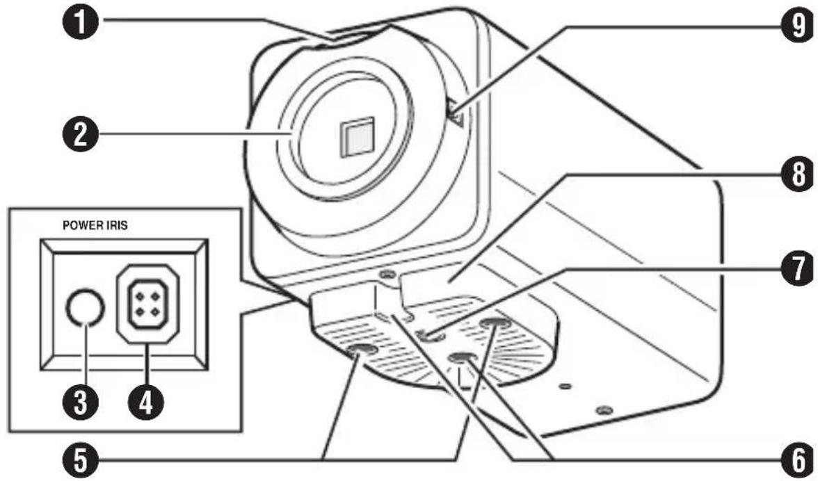
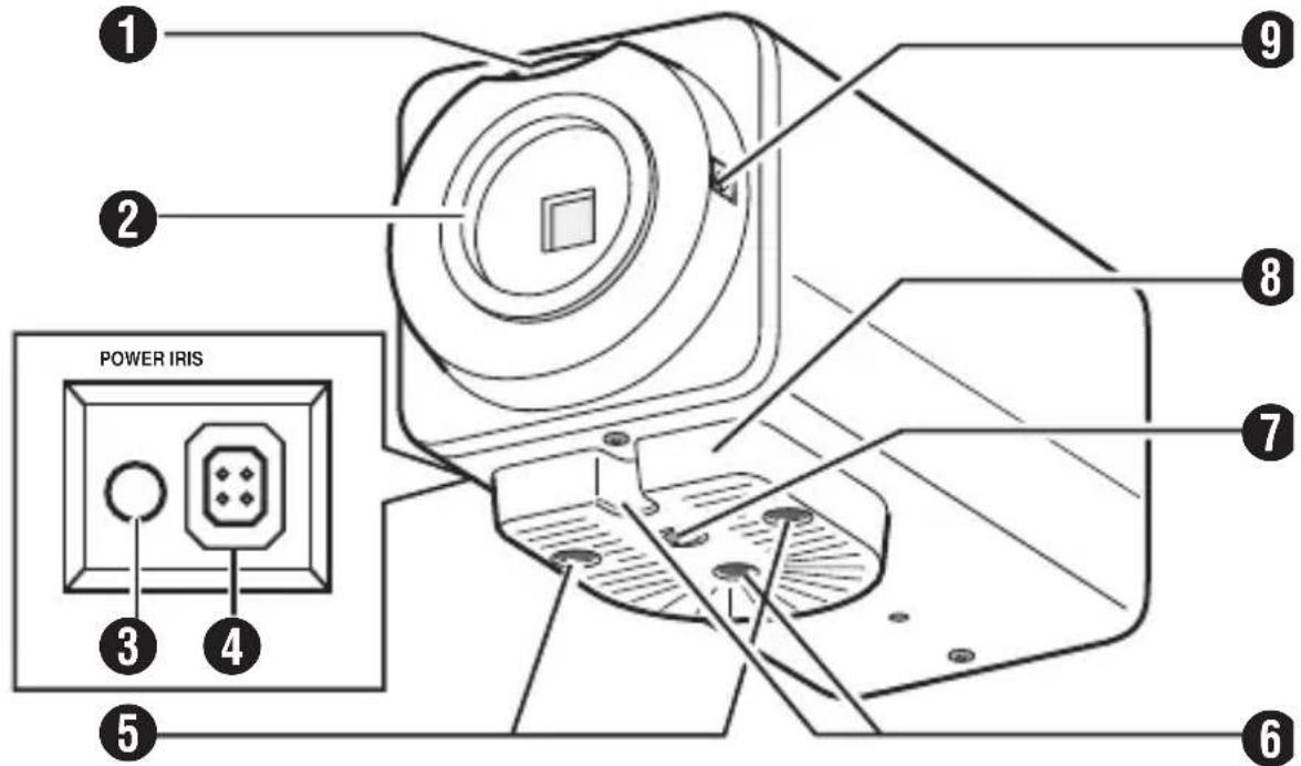
Back focus adjustment ring
Lens mount
3 [POWER] Power indicator
4 [IRIS] Iris terminal
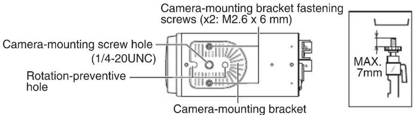
Camera-mounting bracket fastening screws (x2, M2.6 x 6 mm)
Rotation preventive hole
Camera mounting screw hole (1/4-20UNC)
Camera mounting bracket
9 Back focus fastening screw
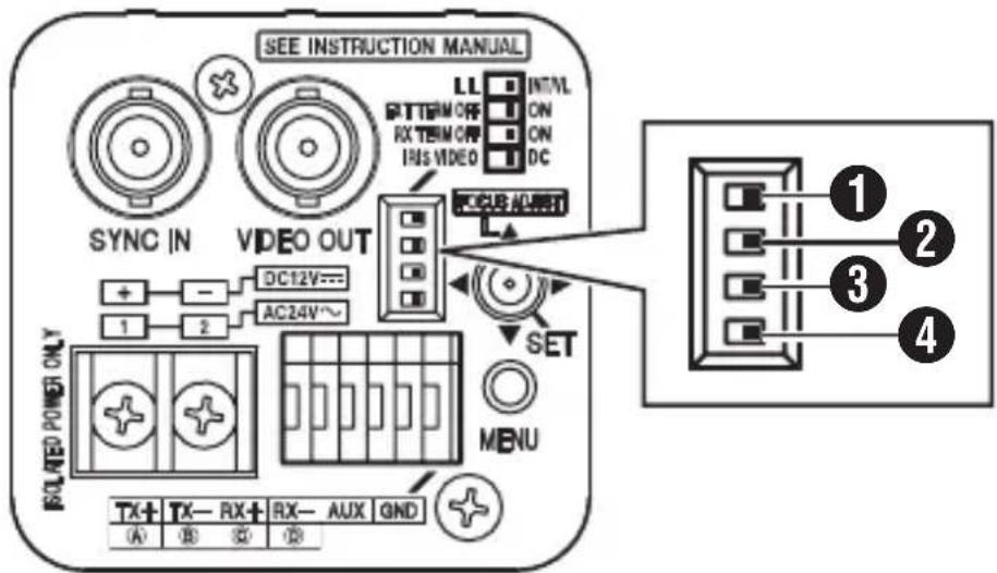
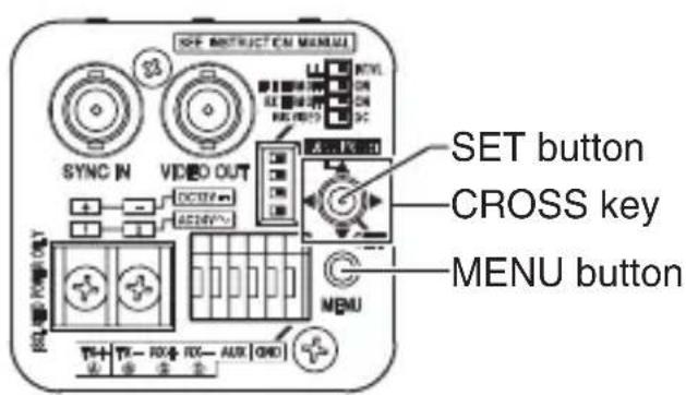
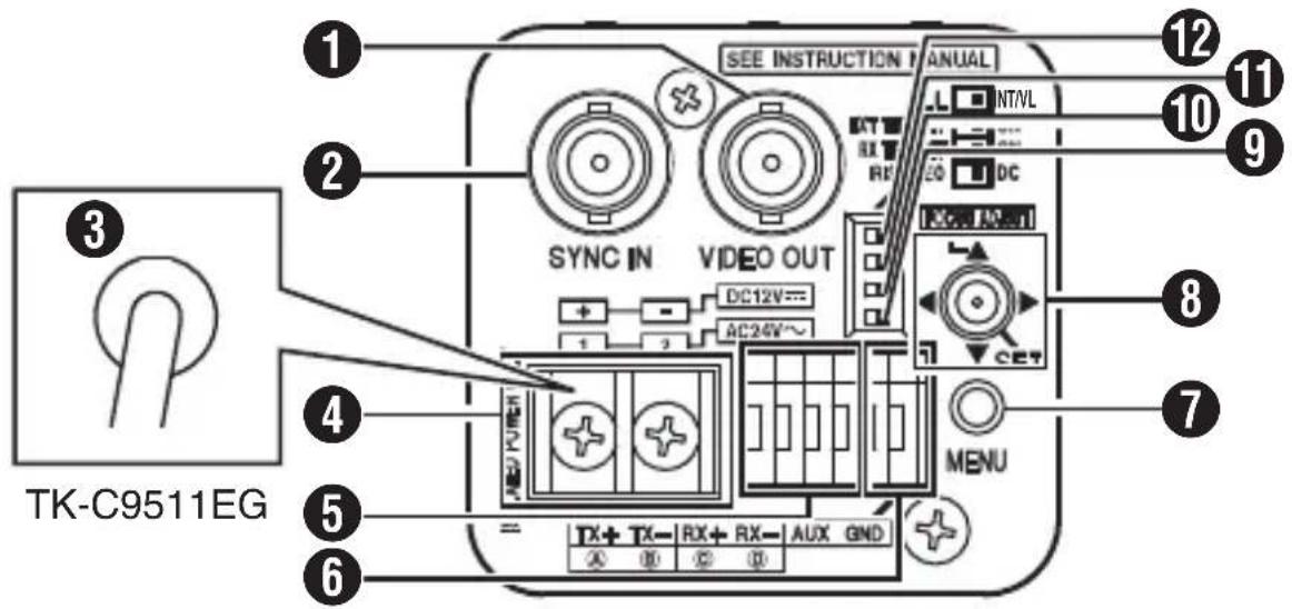
Rear
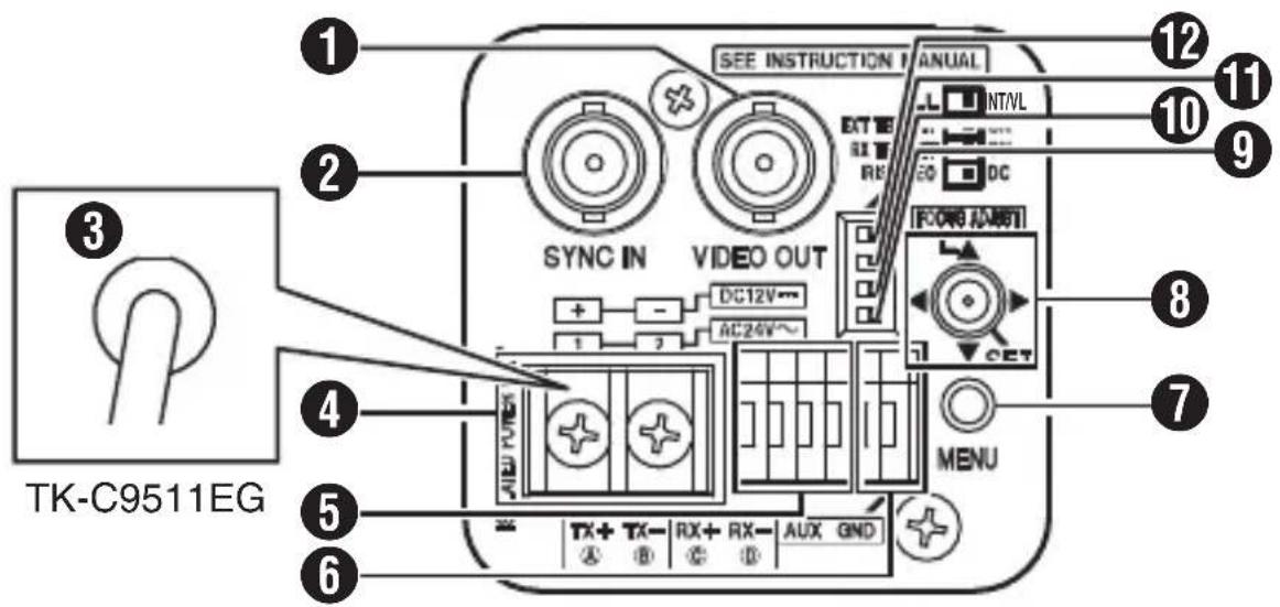
[VIDEO OUT] Video signal output terminal
2 [SYNC IN] Synchronizing signal input terminal
AC 220 V - AC 240 V power cord (TK-C9511EG)
AC 24 V, DC 12 V power input terminal (TK-C9510E)
[TRX+ A, TX- B, RX+ C, RX- D] Control signal connectors (RS-485-compliant)
6 AUX, GND connectors
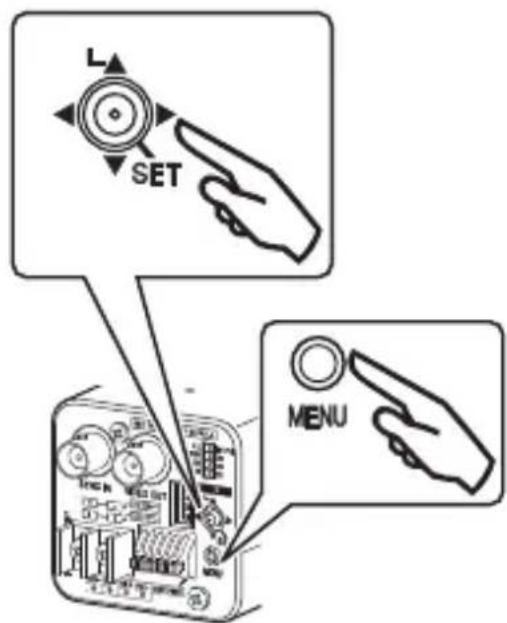
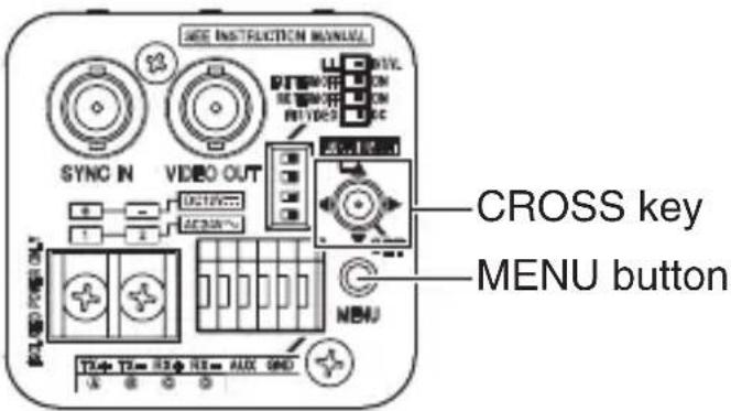
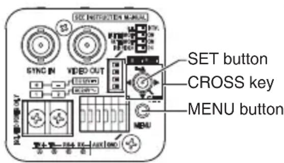
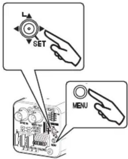
7 [MENU] button
Cross key, [SET] button, [FOCUS ADJUST] button
Memo Press the [SET] button down vertically. If the button is pressed down at an angle, the operation may not be performed.
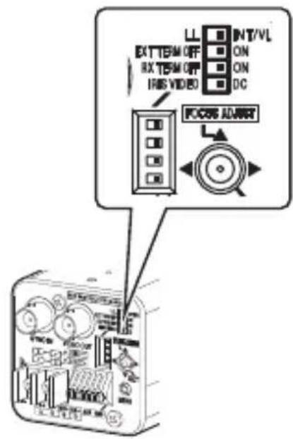
[IRISVIDEO\L DC] Lens selector switch
[RX TERM OFF ON] RX terminal ON/OFF switch
[EXT TERM OFF ON] External synchronous terminal ON/OFF switch
12 [LL\LINTVL] Synchronous system selection switch
Quick Installation
1 Mounting the Lens ( page 20)
2 Connection ( page 21)
3 Mounting the Camera (15 page 24)
4 Switch Settings ( page 26) Adjusting the
B Focus ( page 28)
6 Menu Setting ( page 34) Completion
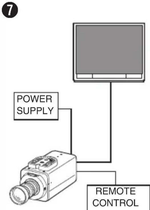
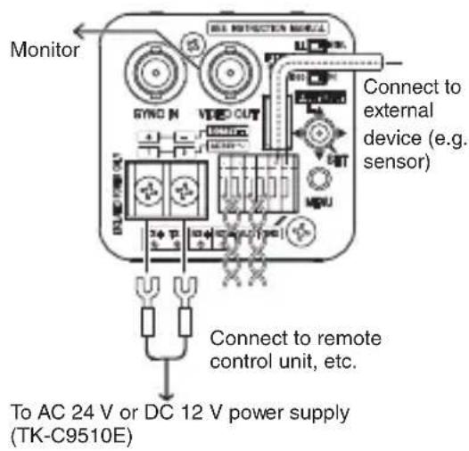
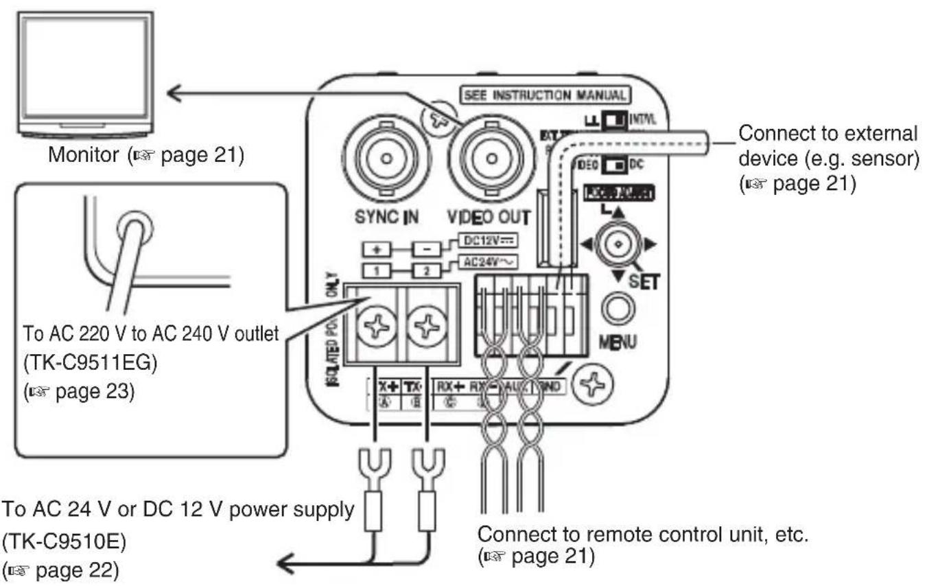
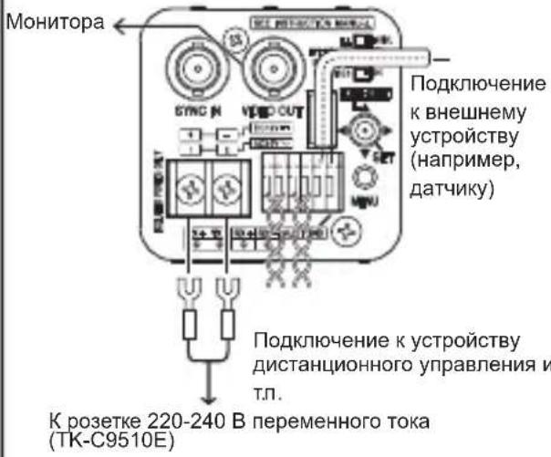
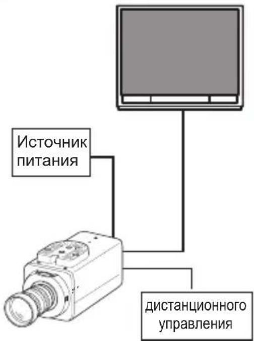
System Connection
Connection Diagram
Memo No. 10
- During control using RM-P2580, select "JCCP" for the [COMMUNICATION] item on the [MAINTENANCE] screen. On the [COMMUNICATION (JCCP)] screen, set [PROTOCOL 1] to "MULTIDROP", and [PROTOCOL 2] to "DUPLEX".
- For control using a device other than RM-P2580, perform setting using the switches and menu screen according to the system in use.
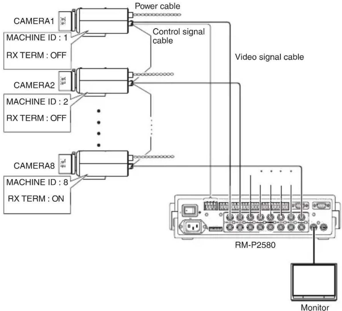
- For systems using RM-P2580, multiple cameras (up to 16 units) are connected using a set of control signal cables. As such, the entire system will not function properly if the switch setting for any one of the connected cameras is incorrect. "Control Signal Cable Connection on Camera (Rear)" (E page 19)
Connection Settings
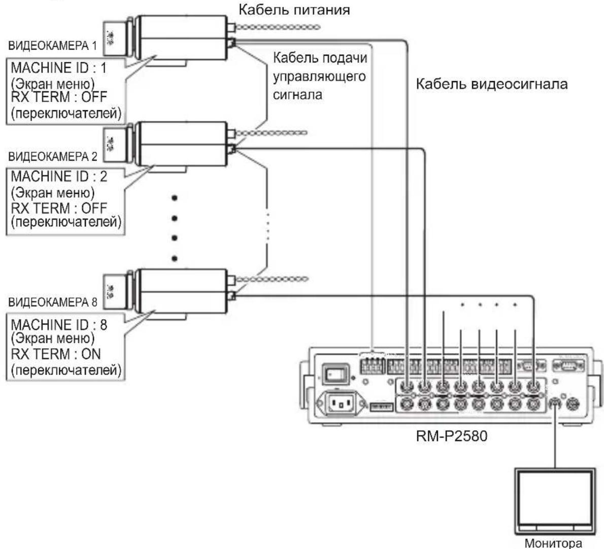
Control Signal Cable Connection on Camera (Rear)
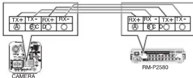
Memo
Connect the cables correctly such that the A,B, C, D marks of the camera terminals coincide with those of the RM-P2580 terminals.
Rear Switch Settings ( page 26)
Set the [RX TERM OFF ON] switch.
Set only the camera connected by the control signal line to "ON". Set to "OFF" for all other cameras.
■ Menu Screen Settings (page 34)
① Select the [MAINTENANCE] item on the [MENU] screen, and press the [SET] button.
The [MAINTENANCE] screen appears.
② Move the cross key up/down to select the [COMMUNICATION] item, move the cross key to the left/right to set to "JCCP", followed by pressing the [SET] button.
The [COMMUNICATION (JCCP)] screen appears.
③ Set [PROTOCOL 1] to "MULTIDROP".
④ Set [PROTOCOL 2] to “DOUBLEX”.
⑤ Set the [MACHINE ID] item according to the number of the RM-P2580[VIDEO INPUT] terminal on each camera.
⑥ Press the [MENU] button to exit setting.
⑦ Turn off and on the power.
Memo - Turn off the power of the device to be used.
Refer also to the instruction manual of the device to be used.
- For details on the type of connection cable and distance, refer to "Power Supply Connection" (15 page 22).
- Control signal cables do not support loop connection.
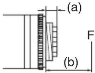
Mounting the Lens
1 Check the mounting method of the lens before mounting.
This camera is compatible with CS-mount lens.
To use a C-mount lens, a C-mount adapter is necessary. For details on the C-mount adapter, consult your JVC dealer.
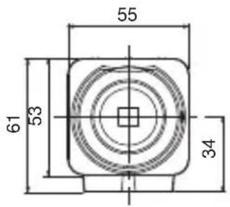
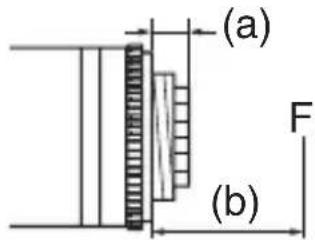
Never use a lens that exceeds the dimension (a) in the below figure as it will damage the inner part of the camera and will not allow normal installation. This will result in a malfunction.
Dimension (a) : 5.5 mm or below
Flange focus (b) : 12.5 mm
2 Turn the lens clockwise and mount it securely on the camera.
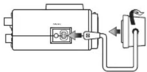
3 Set the [IRIS VIDEO↔DC] Lens selector switch ( page 15) on the rear panel according to the lens in use.
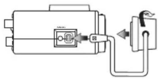
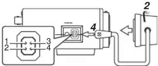
4 Check the pin arrangement and connect the lens cable to the socket.
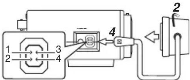
Memo No. 10
- If the plug of the lens cable is different, connect with a four-pin plug. For details on the four-pin plug, consult your JVC dealer. (Part no.: SCV2859-001)
| Pin No. | C IRIS Lens Video Iris Lens |
| 1 Dam | ping (-) +9 V (max. 50 mA) |
| 2 Dam | ping (+) NC |
| 3 Driving (+) Video Signal | |
| 4 Driving (-) GND | |
4 pin plug
Connection
Control Signal Connection
- For systems using RM-P2580, connect using a control signal cable.
- A four-core (two pairs) twisted pair cable with a conductor diameter of at least 0.65 mm and characteristic impedance of 110 is recommended.
- Connect the cables with the TX+/TX- signals forming a pair, and RX+/RX- signals forming another.
- The maximum connection distance with the RM-P2580 is 1200m . (RM-P2580 allows connection of multiple cameras (up to 16 units) to a pair of cable. In this case, the total cable length must not exceed 1200 m. The above applies to cases where the conductor resistance of the cable is 100 or less, and the characteristic impedance is 110 .)
Monitor Connection
Connect using a 75 coaxial cable (BNC), such as RG-59 or RG-11.
Connection (Continued)
Sync Signal Connection
When composite sync signals or composite video signals are input from the [SYNC IN] terminal with the [LL INT / VL] switch set to "INT/VL", external synchronization (V synchronization) can be performed.
Memo
Genlock synchronization cannot be performed for signals with a significant amount of jitter, such as VTRs and video disc recorders. For more details, consult your JVC dealer.
Power Supply Connection
When power is supplied to the camera, the [POWER] power indicator on the side panel lights up.
AC 24 V or DC 12 V (TK-C9510E)
To prevent connection errors or a cable disconnection, use a lug plate to connect to the terminal. The following table shows the connection distances when a two-core VVF (vinyl-insulated vinyl sheath cable) is used. (Reference value)
| Conductor diameter (mm) | Φ 1.0 and more | Φ 1.6 and more | Φ 2.0 and more |
| Max. connection distance (DC 12 V) | 50 m 140 | m 220 m | |
| Max. connection distance (AC 24 V) | 130 m 350 | m 550 m |
Memo
- If thin cables are used, the resistance of the cables will be high, and a significant voltage drop will occur when the camera is at its maximum power consumption. Either use a thick cable with low resistance or place the power supply near to the camera and shorten the length of the cable to restrict the voltage drop at the rated current of camera to below 10% . If voltage drop occurs during operation, the operation will become unstable.
- Do not connect the AC 24 V cable to a commercial power supply. If it is connected by mistake, the internal circuit may be damaged. In this case, stop using the camera and send it to the nearest JVC dealer for inspection.
- Do not connect DC 12 V and AC 24 V cables at the same time.
- When using a DC 12 V power supply, check to ensure that the polarity of the cable is correct.
- The AC 24 V power supply must be isolated from the primary line. (ISOLATED POWER ONLY)
AC 220 V to AC 240 (TK-C9511EG)
When using this camera, install it near the socket so that power disconnection may be made immediately.
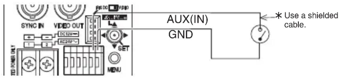
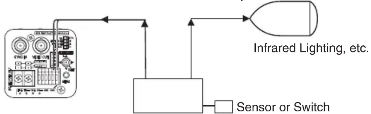
Alarm Signal Connection
For details on the settings, refer to "AUX FUNCTION" ( page 52). The default setting has been set to alarm input. ([IN:ALARM])
Alarm Input
Connect the infrared sensor, door sensor, metal sensor, manual switch sensor and the like.
- To prevent noise from entering the internal circuit, supply non-voltage setting signal to the alarm input signal.
- Do not supply voltage.
- In the [IN POLARITY] item, you can select whether to set to alarm when the contact is short (MAKE), or when the contact is open (BREAK). (15 page 53)
- Supply such that the alarm signal stays at a minimum of 200 ms or more. Otherwise, the alarm signal may not be recognized.
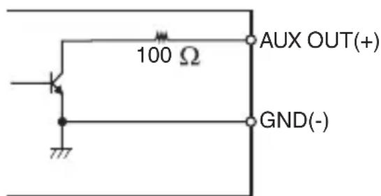
Alarm Output
Connect to alarm devices such as alarm, indicator, light or buzzer.
- The alarm output signal is open collector output and turns ON (or OFF) during an alarm. (Maximum voltage 16 V, current 30 mA or below)
- This terminal has a polarity. Make sure to connect in such a way that a higher voltage is output from the + terminal than from the - terminal. Otherwise, it will result in damages.
- In the [OUT POLARITY] item, you can select whether to set to alarm when the contact is short (MAKE), or when the contact is open (BREAK). ( page 53)
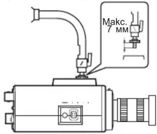
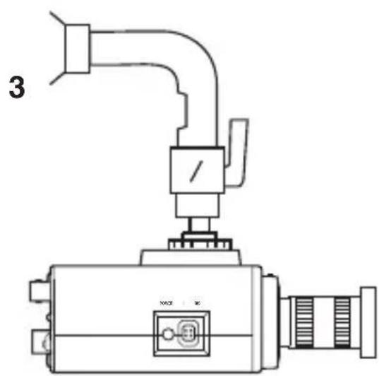
Mounting the Camera
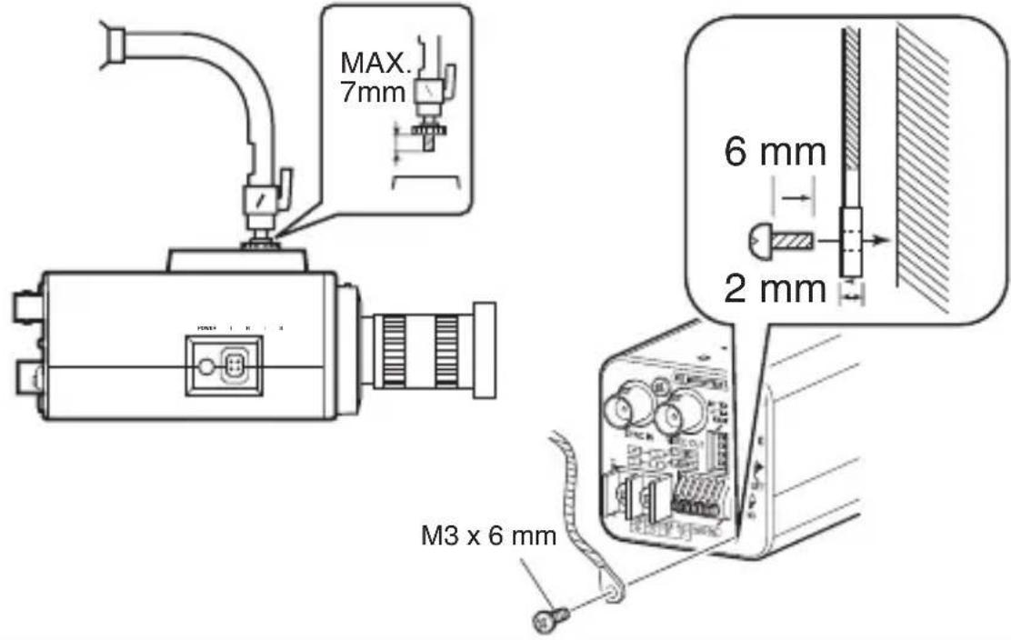
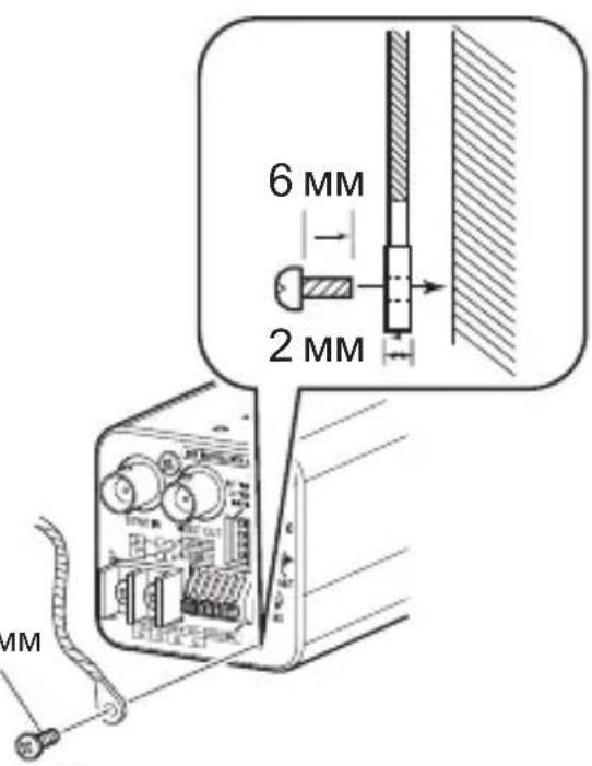
When mounting the camera on a fixer, pan/tilt and the like, use the camera-mounting screw hole located on the camera-mounting bracket. (Length of screw: 7 mm or less)
Note Do not use a screw that is longer than the specified length. It may damage the internal parts.
- Use a camera-mounting screw with a length shorter than 7 mm from the camera-mounting face.
- Use camera-mounting bracket fastening screws with length shorter than 6 ~mm .
Fall Prevention
- Special attention is required when installing the camera to the wall or ceiling. You should not engage in the installation work yourself. Ask a professional to do the job, because injuries and accidents may occur if the camera falls.
- When installing the camera on a fixer, pan/tilt unit and the like, make sure to install it firmly using a rotation-preventive hole to prevent fall.
- To prevent fall, connect the camera to a section with sufficient strength (ceiling slab or channel) using a fall prevention wire.
- Pay attention to the length, strength, routing and material (insulation properties) of the fall prevention wire used.
- Make use of a fall prevention wire that is able to withstand the mass of this camera ( page 71) as well as the total mass of the lens and fixer. Also, make sure that terminal treatment is performed for the wire.
- Use the screw (M3 x 6 mm) on the back of the camera for the installation of the fall prevention wire. Do not use a screw that is longer than 6 mm as it may damage the internal parts.

Note
When mounting the camera to the ceiling, ensure to wear safety glasses to protect the eye from any falling objects.
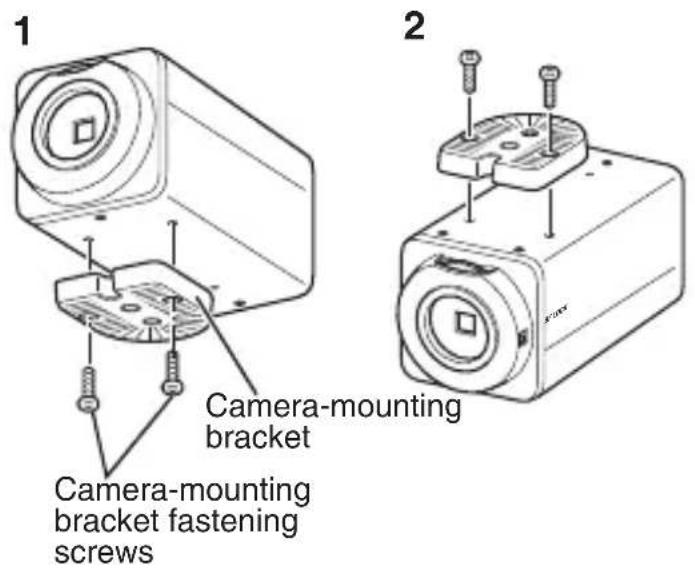
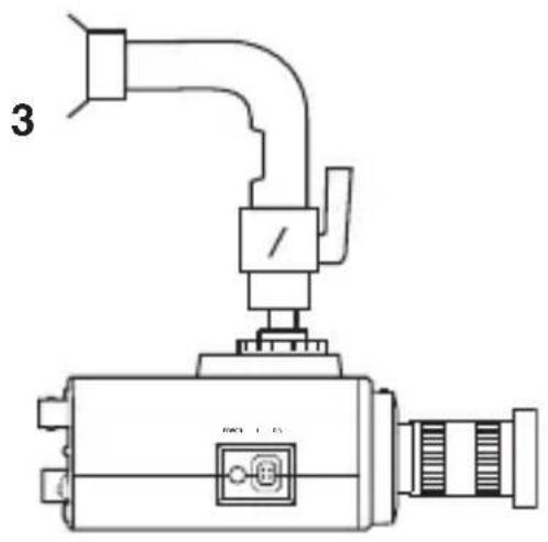
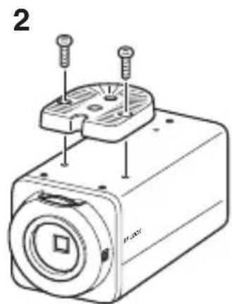
Mounting the Camera-Mounting Bracket on Top of the Camera
The camera-mounting bracket is originally mounted at the bottom of the camera before shipment but it can also be mounted on top of the camera.
When mounting the bracket on top of the camera, make sure to fasten the screws securely.
1 Remove the camera-mounting bracket fastening screws (x2).
The camera-mounting bracket is removed from the camera.
2 Mount the camera-mounting bracket on top of the camera.
3 Mount the camera onto a fixer, pan/tilt unit and the like.
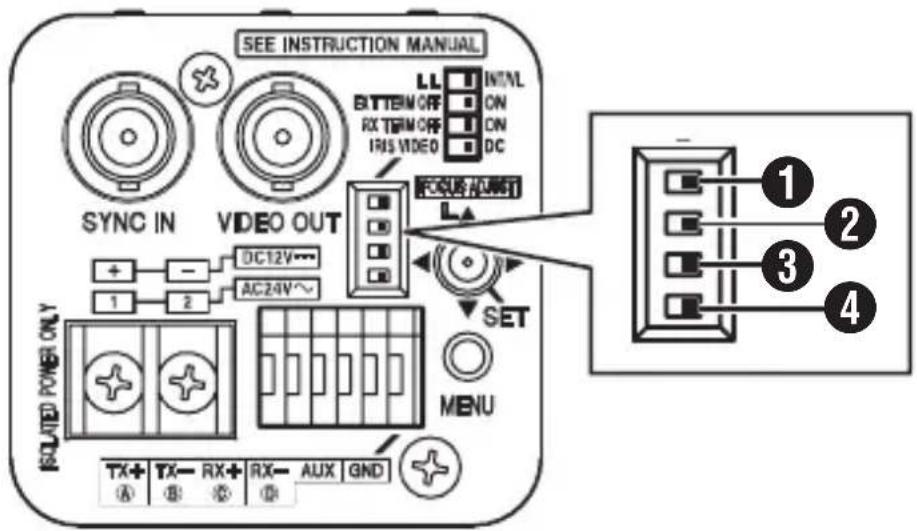
Switch Settings
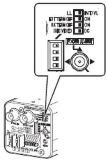
1 [LL\LINTVL] Synchronous system selection switch
For setting the camera's synchronous system.
LL : Set to this option when adjusting the vertical sync of the camera according to the commercial power frequency.
INT/VL : Set to this option during internal synchronization (INT) or external synchronization (V).
(Default setting: INT/VL)
Memo
When a switching unit is used to switch between multiple cameras, adjusting the vertical phase by selecting "LL" will help to reduce sync disruption on the screen caused by switching the camera image.
[EXT TERM OFF ON] External synchronous terminal ON/OFF switch
For setting whether to apply a 75 termination on the sync signal input to the [SYNC IN] terminal.
OFF: Does not terminate at 75
ON: Terminates at 75 Ω.
(Default setting: ON)
3 [RX TERM OFF ON] RX terminal ON/OFF switch
For setting whether to apply termination at a resistance value of 110 between the RX + and RX- control signal connectors.
OFF : Does not terminate.
ON : Terminates.
(Default setting: ON)
Memo
- If the system including this camera employs an M.DROP (Multi DROP, RS-485) system, such as RM-P2580, set only the camera connected at the other end of the control signal cable to "ON", and set all other cameras to "OFF".
- If [PROTOCOL1] on the [COMMUNICATION (JCCP)] screen is set to "P to P", set this switch to "ON".
4 [IRISVIDEO\L DC] Lens selector switch
For setting according to the lens type when an auto iris lens is used.
VIDEO: For lenses built-in with EE amp.
DC: For lenses not built-in with EE amp.
(Default setting: DC)
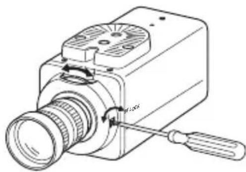
Adjusting the Back Focus
This camera is adjusted to an optimum wide range before shipment but readjustment is required when using zoom lens or when the lens focus ring is out of focus.
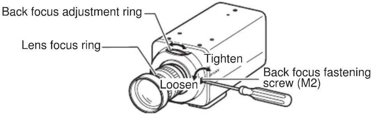
With a Fixed-Focus Lens
If the focus cannot be adjusted correctly with the lens focus ring, adjust the back focus as follows.
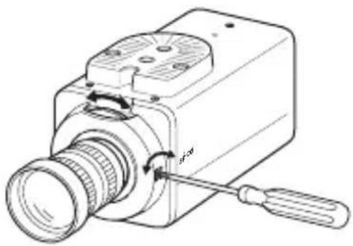
1 Loosen the back focus fastening screw by turning it anticlockwise with a + screwdriver.
2 Shoot some fine patterns on the subject or away from the subject.
3 Turn the lens focus ring to .
4 Turn the back focus adjustment ring to get the best focus.
5 Tighten the back focus fastening screw by turning it clockwise.
With a Zoom Lens
If the image is out of focus when zooming (telephoto - wide angle), adjust the camera as follows.
1 Loosen the back focus fastening screw by turning it anticlockwise with a + screwdriver.
2 Shoot some fine patterns on the subject or away from the subject.
3 Zoom to the maximum telephoto position and turn the lens focus ring to adjust the focus.
4 Zoom to the maximum wide angle position and turn the back focus adjustment ring to adjust the focus.
5 Repeat steps 3 and 4 two or three times.
6 Tighten the back focus fastening screw by turning it clockwise.
Memo No. 10
- When the subject is bright, using ND filter enables accumulate back focus adjustment. ( An ND filter is a filter that reduces light incident on the lens of all wavelengths equally.)
- Use the Focus Adjust mode for easy focusing. "Fine-tuning the Focus" ( page 30)
Fine-tuning the Focus
When adjusting the focus of the auto iris lens, use the Focus Adjust mode for easy focusing as the iris opens and depth of field becomes shallower. (Refer also to the instruction manual of the lens.)
1 Press and hold down the Up cross key.
-
The Focus Adjust mode is activated and "FOCUS ADJUST MODE" appears on the screen.
-
Contours are emphasized as the iris opens.
2 Shoot the subject.
3 Adjust the focus of the auto iris lens.
4 Exit the Focus Adjust mode.
You can also cancel the Focus Adjust mode by moving the cross key or pressing the [MENU] button. The mode is also automatically canceled after about 30 seconds.
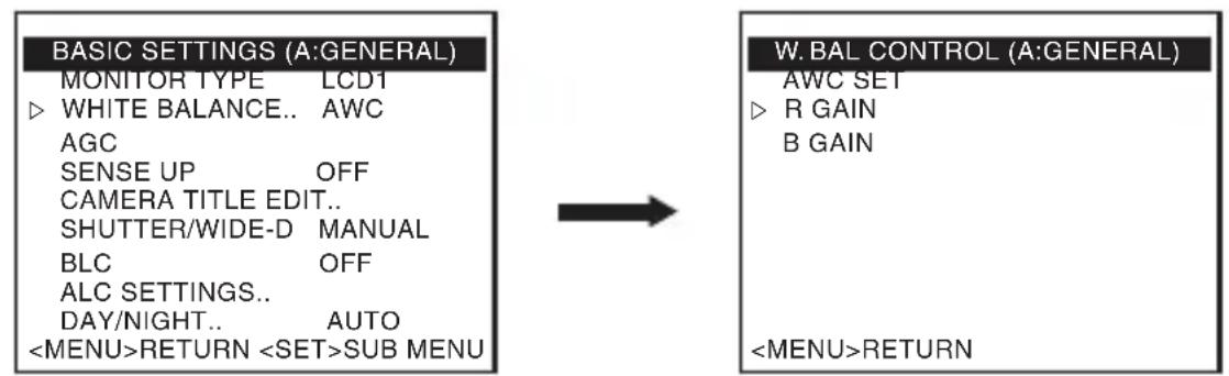
Adjusting the Auto White Balance
Each light source has its own colour temperature. Therefore, when the main light source illuminating the subject is changed, adjust the white balance again. Perform white balance adjustment for each scene file.
1 Press the [MENU] button.
2 Select the scene file for which white balance is to be adjusted. Select [SCENE FILE], and move the cross key to the left/right to select a scene file.
3 Move the cross key up/down to select [BASIC SETTINGS]. The [BASIC SETTINGS] screen appears.
4 Move the cross key up/down to select [WHITE BALANCE].
5 Move the cross key to the left/right to select "AWC", and press the [SET] button.
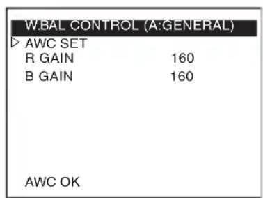
The [W.BAL CONTROL] screen appears.
6 Zoom in to fill the screen with white.
Place a white object at the center of the screen under the same lighting condition as the subject to be shot, and zoom in to fill the screen with white.
7 Select the [AWC SET] item, and press the [SET] button.
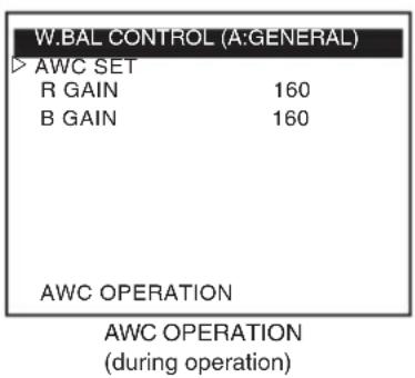
Auto white balance adjustment begins. During operation, "AWC OPERATION" is displayed on the screen.
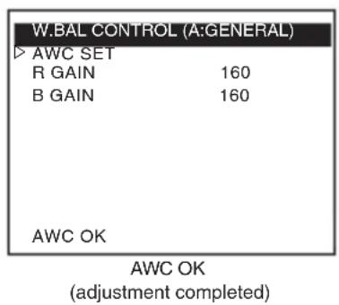
When the appropriate white balance is achieved, "AWC OK" is displayed, and adjustment is complete.
"Error Message" ( page 69)
Memo No. 10
Perform white balance adjustment on each scene file as necessary.
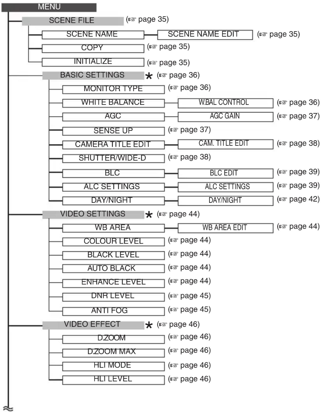
Menu Screen Flow
E-32
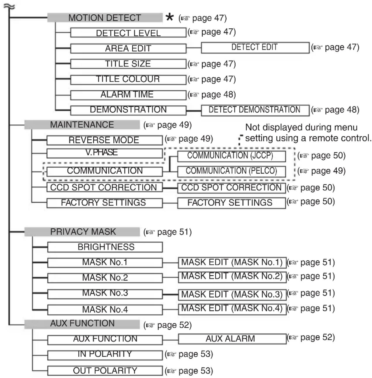
: Item to be set for the selected scene file. Perform setting on each scene file as necessary.
Menu Setting
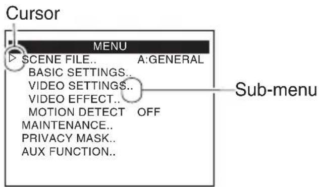
1 Press the MENU button.
2 Move the cross key up/down to align the cursor () with the item to set.
3 Move the cross key to the left/right to change the setting.
When a setting has been changed, a change mark () is displayed.
4 Press the [MENU] button to exit setting.
Memo To display the sub-menu, set the cursor () to an item with sub-menu and press the [SET] button.
SCENEFILE
This camera comes with eight different scene files (SCENE A to SCENE H), which enable detailed image setting according to the shooting condition of the subject.
You can make use of the AUX terminal input or external communication to switch to a different scene file.
"Default Values of Scene Files" ( page 54)
- The default values in the menu table indicate the values when [SCENE FILE] is set to "SCENE A"(GENERAL).
| Item Function and Setting | ||
| SCENE FILE | For selecting the scene file to set. Items including [BASIC SETTINGS], [VIDEO SETTINGS], [VIDEO EFFECT], and [MOTION DETECT] can be set for each scene file. [Setting values: SCENE A, SCENE B, SCENE C, SCENE D, SCENE E, SCENE F, SCENE G, SCENE H] | |
| SCENE NAME | For setting the name of the scene file. Press [SET] to display the [SCENE NAME EDIT] screen, and alter “SCENE NAME” accordingly. (Default values: GENERAL, TRAFFIC, CASINO, NIGHT, LowNoise, WIDE-D, M.DET, AntiFog) (10 page 58) | |
| COPY Copies | the currently opened scene file to another scene file. • Setting example (in the case of “SCENE A”) [Setting values: OFF, A to B, A to C, A to D, A to E, A to F, A to G, A to H] (Default value: OFF) | |
| INITIALIZE Select | select “EXECUTE” and press [SET] to restore the settings of the currently opened scene file to the default values. [Setting values: OFF, EXECUTE] (Default value: OFF) | |
BASIC SETTINGS
| Item Function and Setting | ||
| MONITOR TYPE | Set according to the monitor in use. [Setting values: LCD1, LCD2, LCD3] (Default value: LCD1) | |
| WHITE BALANCE | For selecting a white balance adjustment feature. [Setting values: ATW-N, ATW-W, AWC] (Default value: ATW-W) ATW-N : This is the ATW-N (Auto-Tracking White Balance) mode. The camera adjusts the white balance automatically according to the colour temperature of the scene illumination (colour temperature between 3200K and 8000K). ATW-W : This mode supports a wider range of colour temperature (colour temperature between 2300K and 10000K) than ATW-N. AWC : This is the AWC (Auto White Balance Adjustment) mode. Press the [SET] button to display the [W.BAL CONTROL] screen. | |
| W.BAL CONTROL | AWC SET : Press the [SET] button to adjust and preset the white balance automatically. R GAIN : Adjusts the R (red) hue during AWC. The larger the number, the more reddish the colour becomes. [Setting values: 0 to 255] B GAIN : Adjusts the B (blue) hue during AWC. The larger the number, the more bluish the colour becomes. [Setting values: 0 to 255] | |
| AGC For setting | AGC (Automatic Gain Control). When AGC is working, the screen appears grainy in dark places. Select “FIXED”, and press the [SET] button to display the [AGC GAIN] screen. [Setting values: OFF, MID, HIGH, FIXED](Default value: HIGH) Memo · When [DAY/NIGHT] is set to “AUTO”, “OFF” and “FIXED” cannot be selected. · Even when [AGC] is set to “OFF” or “FIXED”, it is set automatically to “MID” if [DAY/NIGHT] is set to “AUTO”. | |
| AGC GAIN | FIX : For setting the fixed gain value when GAIN [AGC] is set to “FIXED”. [Setting values: 0 dB to 36 dB (in increments of 3 dB)] | |
| SENSE UP | Electronic Sense Up is a function that increases the sensitivity level by lengthening the exposure time. Use this item to set the number of times to increase sensitivity when the subject becomes dark. [Setting values: OFF, x2, x4, x8, x16, x32, x64, x128] (Default value: x4) · Setting example (in the case of “x32”) The sensitivity increases automatically up to 32 times from the standard level. Motion may become unnatural when the sensitivity increases due to the slower shutter speed. Memo · When the setting value is increased, the screen may appear grainy, whitish, or white spots may appear. This is not a malfunction. This setting takes priority over [SHUTTER SPEED]. · When [SHUTTER/WIDE-D] is set to “M.WIDE-D”, “---” is displayed, and the camera operates in the “OFF” setting. | |
BASIC SETTINGS (Continued)
| Item Function and Setting | |
| CAMERA TITLE EDIT | For setting the title to be displayed on the bottom left of the screen. Press the [SET] button to display the [CAM.TITLE EDIT] screen. You can enter up to 24 characters for the title. (10 page 59) |
| SHUTTER/WIDE-D | For setting the shutter operation. [Setting values: MANUAL, M.WIDE-D, A.WIDE-D, AES] (Default value: MANUAL) MANUAL: Operates in the setting set in [SHUTTERTPEED] on the [ALC SETTINGS] screen. M.WIDE-D: The wide dynamic range feature makes subjects with a high contrast appear clearer. The high-speed shutter of dual shutter operates in the setting set in [M.WIDE-D SPEED] on the [ALC SETTINGS] screen. A.WIDE-D: The wide dynamic range feature makes subjects with a high contrast appear clearer, and the high-speed shutter of dual shutter speed is set to Auto. AES: Adjusts the shutter speed automatically according to the brightness. The value set for the [AES LIMIT] item on the [ALC SETTINGS] screen is the maximum limit. Memo • AES operation is intended to be used with the manual iris lens. If auto iris lens is used, AES operation may become unstable as the amount of light will be adjusted by the lens. • "M.WIDE-D" can be selected only when [SENSE UP] is set to "OFF". |
| Item Function and Setting | ||
| BLC | Set this item when the subject is not readily visible due to backlight. Visibility is enhanced by adjusting the photometry area according to the subject.[Setting values: OFF, AREA1 to AREA4, EDIT1, EDIT2] (Default value: OFF)Set this item when the subject is backlit by a strong light source in the same direction. Doing so helps to eliminate unwanted light sources from the photometry area.Select "EDIT1" or "EDIT2", and press the [SET] button to display the [BLC EDIT] screen for setting the photometry area."BLC Photometry Area Setting" (v3 page 66)Memo When [D.ZOOM MAX] is set to "x8", "... is displayed, and the camera operates in the "OFF" settingPhotometry areaAREA 1 AREA 2 AREA 3 AREA 4 | |
| ALC SETTINGS | BRIGHTNESS | Adjusts the video signal brightness level. The larger the value, dark area becomes more visible. The smaller the value, bright area becomes more visible.[Setting values: -5 to NORMAL to 5] (Default value: NORMAL) |
| AVERAGE:PEAK | For setting the exposure detection method using the ratio of the AVERAGE value to PEAK value.[Setting values: 5:5, 6:4, 7:3, 8:2, 9:1, 10:0] (Default value: 8:2)• Setting example5:5 : Increases the "PEAK" value when halation occurs on the highlight area of the screen.10:0: Increases the "AVERAGE" value when areas other than the highlights appear dark. | |
| ALC SETTINGS | ALC PRIORITY | For setting whether to prioritize motion or picture quality when the subject becomes dark. [Setting values: MOTION, COMBO, PICTURE] (Default value: COMBO)MOTION : Prioritizes motion. AGC (Automatic Gain Control) operates with priority.COMBO : Adjusts motion and picture quality equally.PICTURE : Prioritizes picture quality. SENSE UP (Electronic Sense Up) operates with priority.Memo When [AGC] is set to “OFF” or “FIXED”, or when [SENSE UP] is set to “OFF”, “---” is displayed and [ALC PRIORITY] cannot be set.When [AGC] is set to “MID”, or when [AGC] is set to “HIGH” and [SENSE UP] is set to “x2”, “COMBO” cannot be selected. |
| SHUTTER SPEED | For setting the speed of the electronic shutter. The smear phenomenon, where white, vertical stripes appear around a bright light source due to the characteristics of the CCD, becomes more pronounced at a higher shutter speed.[Setting values: 1/50, 1/120, 1/250, 1/500, 1/1000, 1/2000, 1/4000, 1/10000] (Default value: 1/50)Memo When [SHUTTER/WIDE-D] is set to a value other than “MANUAL”, or when [SENSE UP] is set to a value other than “OFF” even though [SHUTTER/WIDE-D] is set to “MANUAL”, “---” is displayed and [SHUTTER SPEED] cannot be set. | |
| ALC SETTINGS | WIDE-DLEVEL | Enables subjects with a high contrast to be seen clearly and naturally.The larger the value, dark area becomes more visible. The smaller the value, bright area becomes more visible. [Setting values: -5 to NORMAL to 5] (Default value: NORMAL)Memo When [SHUTTER/WIDE-D] is not set to“A.WIDE-D” or “M.WIDE-D”,“---” is displayed and [WIDE-D LEVEL] cannot be set. |
| M.WIDE-D SPEED | For setting the high-speed shutter of dual shutter speed when [SHUTTER/WIDE-D] is set to “M.WIDE-D”. [Setting values: 1/500, 1/1000, 1/2000, 1/4000, 1/10000, 1/20000, 1/40000, 1/100000, 1/200000] (Default value: 1/4000)Memo When [SHUTTER/WIDE-D] is not set to “M.WIDE-D”,“---” is displayed and [M.WIDE-D SPEED] cannot be set. | |
| Item Function | Condition and Setting | |
| ALC SETTINGS | AES LIMIT For setting the maximum shutter speed limit when [SHUTTER/WIDE-D] is set to “AES”.[Setting values: 1/1000, 1/2000, 1/4000, 1/10000, 1/20000, 1/40000, 1/100000](Default value: 1/100000)Memo When [SHUTTER/WIDE-D] is not set to “AES”, “---” is displayed and [AES LIMIT] cannot be set. | |
| DAY/NIGHT | For setting the Day/Night mode which switches video images to the Black-and-white mode. Black-and-white mode has better sensitivity than colour mode.[Setting values: COLOUR, B&W, AUTO](Default value: AUTO)COLOUR : Image appears in colour at all times, and does not switch to black-and-white.B&W : Image appears in black-and-white at all times.AUTO : The image appears in colour when the subject is bright, and in black-and-white when it is dark.Press the [SET] button to display the [DAY/NIGHT] screen. | |
| Item Function and Setting | ||
| DAY/NIGHT(Continued) | DAY/NIGHT | For setting the condition for switching video images to the Black-and-white mode when [DAY/NIGHT] is set to "AUTO".AUTO LEVEL: For setting the brightness level at which the camera switches between the Colour and Black-and-white modes. [Setting values: DARK, NORMAL, BRIGHT](Default value: NORMAL)AUTO TIME: For setting the detection time of the brightness level. The camera switches from the Colour mode to Black-and-white mode or vice versa when the brightness level is detected longer than the setting time.[Setting values: 0s, 10s, 20s, 30s](Default value: 30s) |
VIDEO SETTINGS
| Item Function | Condition and Setting |
| WB AREA For setting the white balance target area. Select “ON” and press the [SET] button to display the [WB AREA EDIT] screen. Move the displayed frame up/down/left/right using the cross key to set the area for white balance adjustment. The size of the frame cannot be altered. [Setting values: OFF (full screen), ON (set area)] (Default value: OFF) Memo When [D.ZOOM MAX] is set to “x8”, “---” is displayed, and the camera operates in the “OFF” setting. | Adjusts video signal colour level. [Setting values: -5 (lighter colour) to NORMAL to 5 (darker colour)] (Default value: NORMAL) Memo When [DAY/NIGHT] is set to “B&W”, [COLOUR LEVEL] is not valid even when it is set. |
| COLOUR LEVEL | Adjusts the black level of the video signal. [Setting values: -5 (low level) to NORMAL to 5 (high level)] (Default value: NORMAL) Memo When [MONITOR TYPE] is set to “LCD1” or “LCD2”, “---” is displayed and [BLACK LEVEL] cannot be set. |
| BLACK LEVEL | Increases the black level of the image automatically under low illumination to enhance the visibility of dark subjects. [Setting values: OFF, ON] (Default value: ON) |
| AUTO BLACK | Adjusts contour correction to enhance sharpness on the monitor screen. [Setting values: -5 (soft) to NORMAL to 8 (sharp)] (Default value: NORMAL) Memo When [ANTI FOG] is set to “AUTO”, it is recommended to set [ENHANCE LEVEL] to a value above “6”. |
| ENHANCE LEVEL | |
| Item Function and Setting | |
| DNR LEVEL | For setting DNR (Digital Noise Reduction). When set to “HIGH”, noise is effectively reduced but moving objects can be blurred. [Setting values: LOW, NORMAL, HIGH] (Default value: NORMAL) |
| ANTI FOG | Function to make the image clearer when shooting distant views, or when the image appears blurry due to fog and the like. [Setting values: OFF, AUTO] Memo • When [SHUTTER/WIDE-D] is set to “A.WIDE-D” or “M.WIDE-D”, “---” is displayed, and the camera operates in the “OFF” setting. • During [AGC] operation, the camera operates with [ANTI FOG] in the “OFF” setting. |
VIDEO EFFECT
| Item Function | Condition and Setting |
| D.ZOOM For | setting the digital zoom magnification ratio. [Setting values: VARIABLE, WIDE(x1), MID(x1.4), TELE(x2)] (Default value: VARIABLE) Memo As the video is digitally processed when digital zoom is used, the image quality may deteriorate slightly. |
| D.ZOOM MAX | For setting the upper limit of the digital zoom when it is operated via communication. [Setting values: x2, x4, x8] (Default value: x2) Memo When [D.ZOOM] is not set to “VARIABLE”, “---” is displayed and [D.ZOOM MAX] cannot be set. |
| HLI MODE Darkens extremely bright areas when this is set to “ON”. Enable this item such as when the lighting is too bright. [Setting values: OFF, ON] (Default value: OFF) | |
| HLI LEVEL For setting the “threshold value” of the brightness when [HLI MODE] is set to “ON” to darken extremely bright areas. [Setting values: LOW, NORMAL, HIGH] (Default value: NORMAL) | |
MOTION DETECT
| Item Function and Setting | ||
| MOTION DETECT | For setting the Motion Detect feature to ON/OFF. [Setting values: OFF, ON] (Default value: OFF) Memo When [D.ZOOM MAX] is set to x8, "----" is displayed and the camera operates in the "OFF" setting. | |
| DETECT LEVEL | For setting the level to detect movements. The larger the value, the higher the sensitivity. The smaller the value, the lower the sensitivity. [Setting values: -5 to NORMAL to 5] (Default value: NORMAL) Memo Even the flicker of a fluorescent lamp can be detected when a high value is set. After setting, make sure to check the operation of the Motion Detect function using [DEMONSTRATION]. | |
| AREA EDIT For setting the area in which you do not want to detect motion. ( page 56) | ||
| TITLE SIZE | For selecting the size of the text displayed when Motion Detect is functioning. When set to "DOUBLE", the text displayed will be twice the size of the text in the menu. [Setting values: NORMAL, DOUBLE] (Default value: DOUBLE) | |
| TITLE COLOUR | For setting the colour of the text displayed when Motion Detect is functioning. [Setting values: WHITE, GREEN, CYAN, YELLOW] (Default value: WHITE) | |
| Item Function | Condition and Setting | |
| MOTION DETECT | ALARM TIME For | Setting the output time of the alarm signal and the time to display alarm on the screen. [Setting values: OFF, 5s to 10s, 15s, 20s, 30s, 60s] (Default value: 5s) |
| DEMONSTRATION | Use this to check whether the Motion Detect function is set correctly. Press the [SET] button to start the demonstration. | |
MAINTENANCE
| Item Function and Setting | ||
| REVERSE MODE | For setting the Reverse mode. When set to “ON”, the image is inverted horizontally and vertically. [Setting values: OFF, ON] (Default value: OFF) | |
| V.PHASE Aligns the vertical sync with other cameras during operation of line lock (LL) or external sync (V). [Setting values: -156 to 0 to 156] Memo During operation of internal sync (INT), “---” is displayed and setting is disabled. | ||
| COMMUNICATION | For selecting a communication protocol. The [COMMUNICATION] screen is not displayed during menu setting using a remote control. [Setting values: JCCP, PELCO] | |
| COMMUNICATION (PELCO) | Set this item when operating using a controller that is compliant with Pelco-D and Pelco-P. Set “BAUD RATE” to the same value as that of the controller. Set the "MACHINE ID" while ensuring that it does not duplicate with that for other cameras. BAUD RATE : [Setting values: 2400, 4800, 9600] (Default value: 2400) MACHINE ID : [Setting values: 0 to 255] (Default value: 0) | |
| COMMUNICATION (continued) | COMMUNICATION (JCCP) | Set this item when operating using a controller that is compliant with JCCP. Set “PROTOCOL1” and “PROTOCOL 2” to the same values as those of the controller. Set the “MACHINE ID” while ensuring that it does not duplicate with that for other cameras.PROTOCOL1: [Setting values: P to P, MULTIDROP] (Default value: P to P)PROTOCOL 2: [Setting values: SIMPLEX, DUPLEX] (Default value: DUPLEX)MACHINE ID: [Setting values: 1 to 99] (Default value: 1) |
| CCD SPOT CORRECTION | Compensates for white spots on the CCD. Press the [SET] button to display the items for selection. [Items for selection: CANCEL, EXECUTE]CANCEL: Returns to the [MAINTENANCE] screen EXECUTE: Executes white spot compensation on the CCD. Memo Attach the lens cap before executing white spot compensation on the CCD. Also, turn on the power for 30 minutes to warm up the camera before execution. | |
| FACTORY SETTINGS | Restores camera settings to their default values. Press the [SET] button to display the items for selection. [Items for selection: CANCEL, CLEAR(W/O SCENE), CLEAR(ALL)]CANCEL: Returns to the [MAINTENANCE] screen CLEAR(W/O: Restores settings to the default values SCENE) except for those of scene files CLEAR(ALL): Restores all settings to the default values. | |
PRIVACY MASK
| Item Function | Condition and Setting |
| BRIGHTNESS | For setting the brightness of the part of the image that is masked. The smaller the value, the darker the image. The larger the value, the brighter the image. [Setting values: 0 to 10] (Default value: 10) |
| MASK No.1 | For setting a mask (gray display) to hide areas in an image that you do not want to capture. Select “ON” and press the [SET] button to display the [MASK EDIT] screen for setting the mask. "Privacy Mask Setting" ( page 65) [Setting values: OFF, ON] (Default value: OFF) |
| MASK No.2 | |
| MASK No.3 | |
| MASK No.4 | [Setting values: OFF, ON] (Default value: OFF) OFF: Privacy mask is not displayed. ON: Enables privacy mask. Memo: Privacy mask can be individually set for each number. Up to four masked areas can be set. |
AUX FUNCTION
| Item Function and Setting | |
| AUX FUNCTION | For setting the input/output signal of the AUX terminal. [Setting values: IN:ALARM, IN:SCENE A to IN:SCENE H, OUT:ALARM, OUT:B&W] (Default value: IN:ALARM) Memo Select “IN ALARM”, and press the [SET] button to display the [AUX ALARM] screen. |
| AUX ALARM For performing alarm-related setting when [AUX FUNCTION] is set to “IN ALARM”. TITLE SIZE : For setting the size of the title displayed when alarm signal is input. When set to “DOUBLE”, the text displayed will be twice the size of the text in the menu. [Setting values: NORMAL, DOUBLE] (Default value: DOUBLE) TITLE COLOUR : For setting the colour of the title displayed when alarm signal is input. [Setting values: WHITE, GREEN, CYAN, YELLOW] (Default value: WHITE) ALARM TIME : For setting the time to display alarm on the screen when alarm signal is input. [Setting values: 5s to 10s, 15s, 20s, 30s, 60s] (Default value: 5s) | |
| IN POLARITY | For setting the polarity of the AUX input signal. [Setting values: MAKE, BREAK] (Default value: MAKE) MAKE : Inputs alarm when the contact of the AUX and GND terminals switches from open to close. BREAK : Inputs alarm when the contact of the AUX and GND terminals switches from close to open. Memo When [AUX FUNCTION] is set to “OUT:ALARM” or “OUT:B&W”, “---” is displayed and [IN POLARITY] cannot be set. |
| OUT POLARITY | For setting the polarity of the AUX output signal. [Setting values: MAKE, BREAK] (Default value: MAKE) MAKE : Contact is short when an alarm is initiated. Contact is open when there is no alarm. BREAK : Contact is open when an alarm is initiated. Contact is short when there is no alarm. Memo When [AUX FUNCTION] is set to “IN:ALARM” or “IN:SCENE A to IN:SCENE H”, “---” is displayed and [OUT POLARITY] cannot be set. |
Default Values of Scene Files
Select a setting between "SCENE A" and "SCENE H" according to the surveillance conditions.
All scene files can be customized. ( page 32)
You can also switch the scene file to set via external input. (page 63)
| SCENE FILE | SCENE NAME | Surveillance Condition |
| SCENE A GENERIAL Adaptable to a wide range of subjects in the day or at night. Suitable for general surveillance. The default value of the [SCENE FILE] menu is “SCENE A” (GENERAL). | ||
| SCENE B TRAFFIC Minimizes the motion blur of moving subjects. Suitable for traffic surveillance. | ||
| SCENE C CASINO | Always operates in the Colour mode. Suitable for surveillance of outdoor scenes in the day and indoor scenes with lights. | |
| SCENE D NIGHT Suitable for surveillance of low-lit scenes, such as in the night. Always operates in the Black-and-white mode. | ||
| SCENE E LOWNoise Suitable for surveillance with priority on a clear picture quality with little noise even in a low-lit scene. Switches automatically to the Black-and-white mode according to the brightness of the subject. Low noise helps to save the recording capacity of recording media such as digital recorders. | ||
| SCENE F WIDE-D Suitable for surveillance of scenes such as at entrances or in a backlit scene, where there is a mixture of bright and dark subjects. | ||
| SCENE G M.DET Setting that enables the Motion Detect function which outputs an alarm when human motion or object motion is detected. Alarm can be output to an external device by changing the setting of the [AUX FUNCTION] menu. ( page 52)You can set the operating area for Motion Detect using the [AREA EDIT] item of the [MOTION DETECT] menu. ( page 47) | ||
| SCENE H AntiFog Suitable for surveillance of distant views using a high-magnification zoom lens, or surveillance of subjects in the fog or sand storm. | ||
Motion Detect Area Setting
For setting the area in which Motion Detect functions, which outputs alarm signals when there is movement in the video image. When [AUX FUNCTION] is set to "OUT:ALARM", alarm signals are output from the rear AUX terminal.

Perform Motion Detect setting for each scene file as necessary.
1 On the [MENU] screen, select a scene file for which its Motion Detect area is to be set.
2 On the [MENU] screen, select [MOTION DETECT], and move the cross key to the left/right to set to "ON".
The [MOTION DETECT] screen appears.
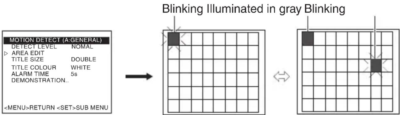
3 Select the [AREA EDIT] item on the [MOTION DETECT] screen, and press the [SET] button.
The [AREA EDIT] screen appears.
4 Move the cross key up/down or to the left/right to select the area you do not want to detect.
The area that appears blinking in black-and-white moves.
5 Press the [SET] button.
The area not to be detected is set, and is illuminated in gray. To cancel the preset area, press the [SET] button again.
6 Repeat steps 4 and 5.
7 After setting is complete, press the [MENU] button. Returns to the [MOTION DETECT] screen.
[MOTION DETECT] Screen [AREA EDTI] Screen
Memo
- The on-screen display position is a rough guide. Check the actual image.
You can check the preset area in the [DEMONSTRATION] item on the [MOTION DETECT] screen.
- The Motion Detect function does not operate until about five seconds after exiting the menu.
- The screen is divided into 48 blocks. Adjust the magnification of the lens such that the subject is large enough to occupy a multiple number of blocks.
Note
- Motion Detect is not a function for preventing theft and fire. It may not function properly depending on the condition of the subject and settings. JVC will not be liable for any accident or damage that arises as a result.
Scene Name/Camera Title Setting
You can change a scene file name (up to eight characters). You can add a title to a camera (up to 24 characters).
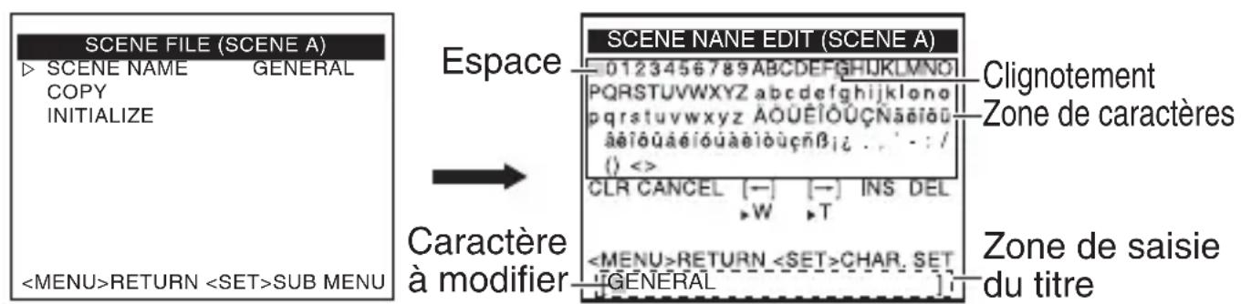
Changing the Scene File Name (SCENE NAME)
"Default Values of Scene Files" ( page 54)
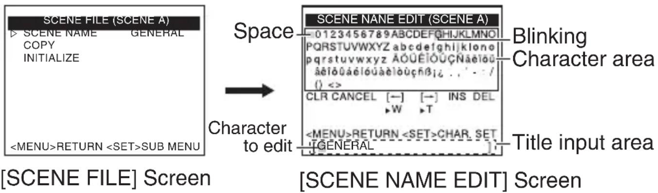
1 On the [MENU] screen, select [SCENE FILE], and move the cross key to the left/right to select the scene file for which you want to specify a name.
The [SCENE FILE] screen appears.
2 Select the [SCENE NAME] item on the [SCENE FILE] screen, and press the [SET] button.
The [SCENE NAME EDIT] screen appears.
The first character in the character list appears blinking. You can input a character in this state.
3 Move the cross key up/down/left/right to select a character from the character list.
The selected character starts blinking.
4 Press the [SET] button.
Confirm the first character for the name, and the second character in the title input area starts blinking.
5 Repeat steps 2 and 3.
6 Press the [MENU] button.
The setting is saved.
Setting the [CAMERA TITLE]
1 Select the [BASIC SETTINGS] item on the [MENU] screen, and press the [SET] button.
The [BASIC SETTINGS] screen appears.
2 Move the cross key up/down to select [CAMERA TITLE EDIT], and press the [SET] button.
The [CAM.TITLE EDIT] screen appears.
- For details on steps 3 to 7, refer to "Changing the Scene File Name (SCENE NAME)" ( page 58).
![JVC TKC9511EG - Setting the [CAMERA TITLE] - 1](/content/2026/03/516796/images/8c649f37574a13fe724ec10d1b953f0c4564a15a8589afd8c8753846f8070165.jpg)
[BASIC MENU] Screen
![JVC TKC9511EG - Setting the [CAMERA TITLE] - 2](/content/2026/03/516796/images/8981320929ffcd39f86fafe55d93e7f664ac16635ed95ced4465ecf56d3339cb.jpg)
[CAMERA EDIT] Screen
Operation Procedure
Select a menu screen display, and press the [SET] button to execute the operation.
| Menu Screen Display | Operation |
| CLR Clears all input characters. | |
| CANCEL Candles the edited content and returns to the previous state. | |
| [←] Moves the cursor in the title input area to the character on the left. | |
| [→] Moves the cursor in the title input area to the character on the right. | |
| INS Inserts a character space and moves all subsequent characters to the right. | |
| DEL Deletes the character selected by the cursor, and moves all subsequent characters to the left by one character space. |
Manual White Balance Adjustment
White balance of this camera can be set to adjust automatically according to the subject. When the automatic adjustment results in, for example, a reddish screen, adjust the white balance manually.
1 Select the [BASIC SETTINGS] item on the [MENU] screen, and press the [SET] button.
The [BASIC SETTINGS] screen appears.
2 Set the [WHITE BALANCE] item on the [BASIC SETTINGS] screen to "AWC", and press the [SET] button.
The [W.BAL CONTROL] screen appears.
3 Move the cross key up/down to select "R GAIN" or "B GAIN".
4 Move the cross key to the left/right to change the hue setting.
The hue changes according to the selected value.
5 Press the [MENU] button to exit.
Memo The settings of "R GAIN" and "B GAIN" are applied when the camera operates in the Colour mode. Adjust the settings in the Colour mode.
[BASIC MENU] Screen
[W. BAL CONTROL] Screen
Output of Black-and-white/Colour Switch Signal
The state of rear AUX terminal can be changed at colour/black-and-white switch. This is enabled when [AUX FUNCTION] is set to "OUT:B&W".
page 52)
Setting [AUX FUNCTION] to "OUT:B&W"
1 Select the [AUX FUNCTION] item on the [MENU] screen, and press the [SET] button.
The [AUX FUNCTION] screen appears.
2 Move the cross key up/down to select [AUX FUNCTION].
3 Move the cross key to the left/right to set to "OUT:B&W".
4 Press the [MENU] button to exit.
Returns to the [MENU] screen.
MENUE
SCENEFILE.A:GENERAL
BASIC SETTINGS
VIDEO SETTINGS...
VIDEO EFFECT..
MOTION DETECT OFF
MAINTENANCE.
PRIVACY MASK
AUX FUNCTION...
[MENU] Screen

AUX FUNCTION
AUX FUNCTION OUT:B&W
INPUT POLARITY MAKE
OUT POLARITY MAKE
[AUX FUNCTION] Screen
Output of Black-and-white/Colour Switch Signal (Continued)
Setting [DAY/NIGHT] to "AUTO"
1 Select the [BASIC SETTINGS] item on the [MENU] screen, and press the [SET] button.
The [BASIC SETTINGS] screen appears.
2 Move the cross key up/down to select [DAY/NIGHT].
3 Move the cross key to the left/right to set to "AUTO".
![JVC TKC9511EG - Setting [DAY/NIGHT] to "AUTO" - 1](/content/2026/03/516796/images/756708e4389ca54a2b743b4c6b4cbf76da1a07c8e74cd5285663f8c63d30029c.jpg)
[MENU] Screen
![JVC TKC9511EG - Setting [DAY/NIGHT] to "AUTO" - 2](/content/2026/03/516796/images/e00754954974251b114415c163c160c6bc2ffd3c999c24115cdb85852f81b065.jpg)
![JVC TKC9511EG - Setting [DAY/NIGHT] to "AUTO" - 3](/content/2026/03/516796/images/ad467583c93d91ba411e31471220df7c4cb0cc5539a0635cd5e72df9690136c1.jpg)
[BASIC SETTINGS] Screen
4 Press the [MENU] button to exit.
Returns to the [MENU] screen.
Memo
- Even when [AUX FUNCTION] is set to "OUT:B&W", the state of rear AUX terminal is not changed if [DAY/NIGHT] on the [BASIC SETTINGS] screen is set to "COLOUR".
-
When a near-infrared light is used, the image may switch from black-and-white to colour if there is strong reflection from the subject. To ensure that switching is performed correctly, it is recommended that users make use of the setting that controls black-and-white/colour switching signal externally.
-
The image may go out of focus due to the lens performance when the lighting on the subject becomes a near-infrared light source. In this case, make use of a lens that supports near-infrared light.
Controlling Black-and-white/Colour Switch Signal Externally
Switching signal from an external controller can be used to switch the image on the camera between colour/black-and-white, and also enable simultaneous operation of lighting such as near-infrared light. For details on the devices to connect, consult your JVC dealer.
External Controller
Scene file is available to change AGC and SHUTTER Settings at switching Black-and-white/Colour Mode
1 Set "SCENE C" to the setting for day use (colour).
2 Set "SCENE D" to the setting for night use (black-and-white).
3 Set [SCENE FILE] on the [MENU] screen to "CASINO" (SCENE C).
4 Set [AUX FUNCTION] on the [MENU] screen to "IN:SCENE D". For details on the settings, refer to "AUX FUNCTION" ( page 52).
Memo No. 10
When in the Black-and-white/Colour mode, the image may go out of focus due to the lens performance when the lighting on the subject becomes a near-infrared light source. In this case, make use of a lens that supports near-infrared light.
Controlling Black-and-white/Colour Switch Signal Externally (Continued)
Switching Between Day/Night Video Setting Using Scene File Function
- Example: Switching to SCENE D when AUX input is in the Make state
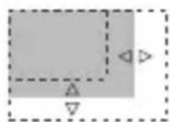
Privacy Mask Setting
1 Select the [PRIVACY MASK] item on the [MENU] screen, and press the [SET] button.
The [PRIVACY MASK] screen appears.
2 Move the cross key up/down to select [MASK No.], move the cross key to the left/right to select "ON", followed by pressing the [SET] button.
The [MASK EDIT (MASK No.)] screen appears.
3 Use the cross key to edit the left/upper margin of the mask.
4 Press the [SET] button.
The screen to edit the right/ lower margin of the mask appears.
5 Use the cross key to edit the right/bottom margin of the mask.
Memo No. 10
Press the [SET] button to switch between the screen to edit the left/upper margin of the mask and the screen to edit the right/ lower margin of the mask.
6 Press the [MENU] button.
The mask boundary of the selected number is saved, and the screen returns to the [PRIVACY MASK] screen.
7 Repeat steps 2 to 6 to set all desired masks (MASK No.1 to MASK No.4).
8 Press the [MENU] button to exit.
Returns to the [MENU] screen.
MENU
SCENEFILE... A:GENERAL
BASIC SETTINGS
VIDEO SETTINGS...
VIDEO EFFECT...
MOTION DETECT OFF
MAINTENANCE..
PRIVACY MASK
AUX FUNCTION..
[MENU] Screen
MASKEDIT (MASK No.1)
(MASK No.1)

PRIVACY MASK
BRIGHTNESS
MASK No.1
MASK No.2
MASK No.3
MASK No.4
OFF
OFF
OFF
OFF
[PRIVACY MASK] Screer
MASKEDIT(MASKNo.1)
(MASK No.1)
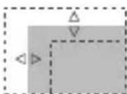
BLC Photometry Area Setting
For setting the photometry area for backlight compensation. You can perform setting on two types of screens, [EDIT1] and [EDIT2].
1 Select the [BLC] item on the [BASIC SETTINGS] screen, and select [EDIT1].
2 Press the [SET] button.
The [BLC EDIT] screen appears.
3 Use the cross key to edit the left/top area, and press the [SET] button.
An editing screen for the right/bottom area appears.
4 Use the cross key to edit the right/bottom area.
Memo No. 10
Press the [SET] button to switch between the screen to edit the left/top area and the screen to edit the right/bottom area.
5 Press the [MENU] button to exit.
Returns to the [BASIC SETTINGS] screen.
- When using the preset photometry area, set [BLC] to "EDIT1" or "EDIT2". (R page 39)
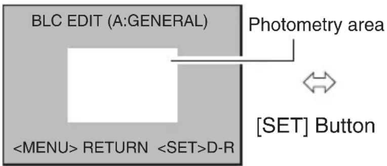
[EDIT1] Screen
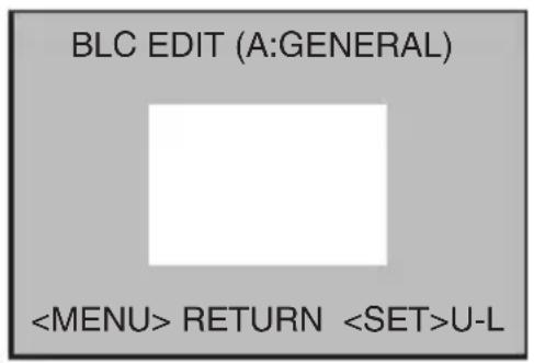
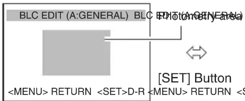

[EDIT1] Screen
- The photometry areas for the [EDIT1] and [EDIT2] screens are different.
- The on-screen display position is a rough guide.
Troubleshooting
Operational Error
| State Action | Reference Page | ||
| Image is not displayed. | ·Check the power indicator on the camera, and also whether the coaxial cable is connected properly. ·Check whether the brightness and contrast of the monitor are set appropriately. ·Check whether the cable length is appropriate. ·Check whether the auto iris lens cable is correctly connected. ·Check whether the switch is set correctly according to the auto iris lens in use.(IRIS VIDEO↔DC) | ·page 22 ·page 44 ·page 20 ·page 20 ·page 20 | |
| Image appears blurry. | ·Check whether dirt such as soil or dust is attached to the camera lens. ·Check whether the focus is correctly adjusted. | ·- ·page 28 ·page 30 | |
Troubleshooting (Continued)
Operational Error (continued)
| State Action | Reference Page | ||
| Operation | Unable to switch between AUX input/output. | ·Check whether the video cable is correctly connected. ·Check whether the [AUX FUNCTION] item is correctly set. | page 21 page 52 |
| The [SET] button operation cannot be recognized correctly. | ·Press the [SET] button down vertically. If the button is pressed down at an angle, the operation may not be performed. | - | |
Error Display
| Error Message Actio | Reference Page | ||
| AWC | AWC ERROR:NG OBJECT | There is insufficient white in the subject, or the colour temperature setting is inappropriate. Fill the screen with a white object thoroughly and adjust the white balance again. | page 31page 60 |
| AWC ERROR:LOW LIGHT | The lighting is too dim. (Insufficient illumination) Brighten the lighting and adjust the white balance again. | page 31page 60 | |
| AWC:ERROR:HIGH LIGHT | The lighting is too bright. (Excessive illumination) Darken the lighting and adjust the white balance again. | page 31page 60 | |
| AWC ERROR:TIME OVER | There are changes in the state of the subject. (Lighting variation) Stabilize the subject and adjust the white balance again. | page 31page 60 | |
Index
A AGC 37
ALC SETTINGS 39
Auto White Balance Adjustment (AWC) 36
Automatic Electronic Shutter (AES) 38
B Back Focus 28
BLC 39
C Camera Title 38,59
D DAY/NIGHT 42
Digital Noise Reduction (DNR) 45
F Focus Adjust 30
M MONITOR TYPE 36
P Power Supply Connection 22
PRIVACY MASK 51,65
SCENEFILE 35,58
SENSE UP 37
W WHITE BALANCE 36, 60
WIDE-D 38
Specifications
| Horizontal resolution : 550TV lines (typical) | |
| Video S/N ratio : 52 dB (typical, AGC OFF) | |
| Minimum illumination | Colour mode: 0.05 lx (Standard, 50 %, F1.2, AGC HIGH) 0.025 lx (Standard, 25 %, F1.2, AGC HIGH) Black-and-white mode: 0.006 lx (Standard, 50 %, F1.2, AGC HIGH) 0.003 lx (Standard, 25 %, F1.2, AGC HIGH) |
| Lens mount | CS mount |
| Power supply | AC 24 V 50 Hz/60 Hz, DC 12 V (TK-C9510E) AC 220 V - AC 240 V 50 Hz/60 Hz (TK-C9511EG) |
| Length of power supply cable | 1900 mm (TK-C9511EG) |
| Current consumption | 390 mA (TK-C9510E) 60 mA (TK-C9511EG) |
| Ambient temperature | -10 °C to 50 °C (operating range) 0 °C to 40 °C (recommended) |
| Mass | 310 g (TK-C9510E) 490 g (TK-C9511EG) |
| Accessories | Instructions × 1 CD-ROM × 1 |
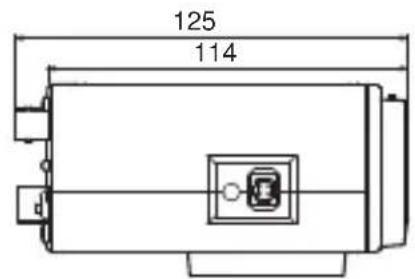
Dimensional Outline (Unit: mm)
1/4 20UNC 37

* Specifications and appearance of this camera are subject to change for improvement without prior notice.
COLOURVIDEOCAMERA
TK-C9510E
MANUEL D'INSTRUCTIONS
TK-C9511EG
AVERTISSEMENT
POUR EVITER LES RISQUES D'INCENDIE OU D'ELECTRO-CUTION, NE PAS EXPOSER L'APPAREIL A L'HUMIDITE OU A LA PLUIE.
I'écran [SCENE FILE] I'écran [SCENE NAME EDIT]
(Ajuste completeness)
Supporta i protocolli Pelco-D e Pelco-P
PoiDepKnBaet npToKoJIb Pelco-D n Pelco-P
:O6o3Haayet MepbI ppeIOCTOpOXHOCTH BO Bpemra60TbI.
3ametkn
: O6o3Naaet CcblNoHyu INΦopMaunO o6 orpaHnueHnax ΦyHKn, nCNOJb3OBaHnI TaK daJe.
:O6o3haaet cnpaBOUHyo CTpaHnUy IIN nyHKT.
CopejkaHne pyKOBODCTBa
- ABTOPCKne npaba Ha daHHoe pyKOBOdCTBO npHaadJeKaT KOMnAHn JVC. DaHHoe pyKOBOdCTBO He MoXeT 6bITb BOCpON3BeDeHO, ZeIHKOM nIN qACTnUHO, 6e3 ppeBapNTeJIbHOrO CORlacn KOMnAHn.
Ha3BaHnra TOBapOB dpyrnx KOMnaHn, ynOMnHaembIe B DaHHOM pKoBOOCTBe, YBnIOTcT TOPROBbIMN MapKaMn IIN 3apeHnCTpnpOBaHHbIMN TOPROBbIMN MapKaMn COOTBETCTByHOuNX KOMnAHH. 3HaKn TM, R N C B HAcToaIeM pyKOBoOCTBe OnyUeHbl.
-Дизай,ТexнческіехаразгетерпскиИдругіпapametрbl,привedeHHьeВданHompyKOBODCTBe,MORYT6bITbИЗMeHeHbIВцеляуЧшеня6e3пpeДВapNTeЛьНOrOуВEDOMJIeHnY.
Ha nllIOCTpaunx B daHHOM pyKOBOdCTBe NCNoJIb3YeTcM OndeJIb TK-C9510E.
MepbI ppeoctopoxhoctn npn pa6ote
MecTo XpaHeHnI 3KcPnyatauN
He yctaHabnBaIteKaMepyBcneDyUOxMecTax.
B MeCTax, NOBBePKeHHbIX BO3DeIeCTBNU DOJxN IJI N BJaRn.
B MeCTax C NOBbIeHHbIM COepeXaHHeM npa IIN MaCna, HApPImEp, Ha KyxHe.
B MeCTax, B KOTOpbIX OkpykaIOUaI TeMnepaTpya NOHIMaETcB bIwe HII ONyCKaETcH NHXe DOnyCTmOro 3NaueHnra (OT - 10^ do 50^ )
B MeCTe, rIe BbIeJIaOTcKoppo3nHbIe ra3bl.
B6n3n nCTOuHnKOB paIIOaKTINBHoro n3nyeHn, peHTreHOBCKnx lyuei, CNbHbIX paIIOBOJN nIIM MaHETn3Ma.
B MeCTax, NOBepXeHHbIX Bn6paCm.
B cnIbHo 3aarp3HeHHbIX MeCTax.
OrpaHnueHne OTBETCTBeHHOCTN
-Функцяобнаруженьядвиженья HeЯВлЯETССpeДCTBOMпpeДOTВрашенья XИшенья ИПИ NOЖараз.Мы He Hecem OTBETCTBEHHOCTh 3aЛIOБbie BO3MOXHьe NOBpeKDeHry.
- Mbl He Hecem HnkaKoI OTBeTCTBeHHOCTn 3a BO3MOXHbIe HeyIO6CTBa I HENpNIArTHOCTn, Bbl3BaHHbIe HApUWeHNEm HEnpNIKOCHOBEHOCHTn JINuHOJ Xn3HN B pe3yJIbTaTe CbeMKn DaHHoJ KaMepoJ.
Ipoue cBeHnra
B cnyuae nepeHockn BndeokamepbI n3 XOJODHO MecTa B TeTIOE NOMEUHe Ha ee DeTajx BO3MOXHO NOBLeHne KOHDeHCaUN, YTO MOKET CTaTB pNCHOH NOBHeNc c6oEB B paBoTe. B 3tOM cnyuae neped BKIOUeHNem NITAHN OCTaBbTe KaMepy B TeueHne yaca npN KOMHaTHOH TempepaType.
Bcnyae kpaKOBpeMeHHoro OTKJIIOUeHnI NIN CHNXEHNHaNPJXeHn IcTOHnKa nHTAHN I3-3a BCbIbIKMOHNN, BKIOUeHn KONDUNOHEpa BO3dYxA N. d. 306paXeHne MoXeT 6bITb NCKaXeHO NIN NpePaBaTbcr C NOMExAMN.
- Пи снжehин haopjxeHЯ nCTOuHnKa nHTaHn KaMepbl cpa6aTbIbAet BCTpoEHna
ць 3aunbl, И kaMepa moKet 6blb OTKJIoueHa.ИсnoJb3yIte pa6ouee haopjxeHne
В пpeJenax ±10 % ДЯ habржehЯ nCTOuHnKa nHTaHn KaMepbl.
He HappaBnIte oBeKTHBa HA MoUHbIe NCTOuHNKn CBeta, HApPIMep, coHHce. 3To npBedeT K c6oM B pa6ote KaMepbI.
- IpepeKpeneHem KamepbI B MecTe NocToHHoYcTaHOBKn Heo6xOIMOn
npNKpeNTb NCNoJIb3YeMbIe JINH3bl N pOBepNTb 3aDHIOΦOKyCnPOBky.
- Пи сьемke obbeKToB C BbICOKIM CBeTOn3JyuYeHnEM (HaPpIMep, JAmNbl) BOKpyr Hnx Ha n3O6paXeHn MOryT NOBbTBcB VePTiKaJIbHbIe NOLocbl (Cma3bIBaHnE) nIN pa3MbITOCtB (6JIOMnHr). 3TO Oco6eHHocTb I3CMatpnUcbl, IN He ABJREc TpN3HaKOM HeNCnPpABHOCTN.
- Pn 3KcNpyatau KamepbB yCNOBnaX C NOBbIweHHoTEmnpaTypoHa 3KpaHe BO3MOxHO NOBJIeHne BepTKaJIbHbIX NOLoc. 3TO Oco6EHHOCTb P3CMATPNzbl, H He ABJETcPn3HaKOM HenCnPaBHOCTn.
- Пи ИСПОЛБЗOBAHИКаМЕРБIC yCTaHOBKоДЯ пapametpa [AGC] 3наченя „MID" ИИ „HIGH" npOncxODNT aBtOMaTnueeCKoe NObIшЕнe YUВСТВИTeЛьНOCTHN B CNYuae TemHOrO n3ObpaJKeHЯ, B pe3yЛbTaTe qero Ha 3KpaHe MOKeT npOraBJIaTBcR 3ePHNCTOcTb. 3TO He IYBJIaETcR pPn3HaKOM HeINCPaBHOCTN.
Korda nepeknioateIb [DAY/NIGHT] yctahOBnEn B noJIOxHne ,AUTO" kAmepa nepeknioaetcna HyePHo-6eJIoe n3O6paXeHne B TEMhbx MeCTax. Tak KaB 3TOM clyuae NOBbIaETcra yPOBeHb YyBCTBNTeJIbHOCTN, n3O6paXeHne Ha 3KpaHe MOKeT 6bITb 3epHNCTbIM C OTo6paXeHneM 60JIbWeTo KOINueCTBa 6eJIbIX PATEH. Pn pepeKnIOUeHIn MExdy peKImamMBiJeTcRaOJIeE JpKaA O6JaCTb 3KpaHa, a BNIMOCtB MoXeT 6bITb CHNXeHa. 3TO He ABnRETCnPn3HaKOM HeNCnPabHOCTN.
Korda nla [WHITE BALANCE] kamepbI yctaHOBJeH napametp ,ATW-N" IIN ,ATW-W", zBeTOBOJ TOH HeKOtOpbIX oBbeKTOB MoKeT CnErKa OTIIuHaTbCRA OT qAKTInueCKoro ZBeta B 3aBNCIMoCTN OT YCIOBNI OBekTa. 3TO npONCXODNT N3-3a npINcUNa DeiCTBna ZeHN aBTOMaTHueCKo peYIpnpOBKn BaJIaHca BeIoro N He YBnEeTcR npN3HaKOM HeNCnPabHOctn.
- Пи посякюецни сцьет Horo Ha chepho-бение n3obpaжень, может pa3daBaTbCЯ pa6очий 3Byk Илп посякюецни ФильТрOB, a n3obpaжень может на cekyнду CTaTb TemhbIM И НAm MOrYT BO3HnKHyTbnomexN. 3TO HeЯВЯETcя риЗнakOM HeNCnPaBHOCTN.
- Ⅲ-3a npHcnpa pa6Obl TpexMepHO rHcPpOBoro CHnKeHnI NOMEX KAMepbI pR cBEmKe DnKxUxNcxr OObEKTOB MOKeT BO3HnKaTb 3aepKka N3o6paXeHn. 3aepKka n3o6paXeHn Ha6OJee Yacto npocXoDnt, KOrda Bo BpeMЯ nCNoJIb3OBAHnЯ KAMEpbI napaMeTp [DNR LEVEL] yCTaHOBJIeH Na "HIGH". 3To He JbIaeTcR npn3HaKOM HeuCnPaBHOCTn.
Ha3BaHnJaTeTaJeN
Перед/Верх/сторoga
1 Kolbuto hactpoiKn 3aHero okyca
KpenJIeHne o6bekTnBa
3 Инданкатор петашия [POWER]
4 THe3do dnaΦparMbI [IRIS]
KpePnIe BnHTbIMOHTaXHOro KPOHtTeHa KaMepbl (2 Wt., M2,6 x 6 MM)
OTBepctne orpaHnueHn BpauneHn
OTBepTnI dIe KpeIeXHOro BnHTa KaMepbl (1/4-20UNC)
MOHTaXHbI KpoHwTeH KaMepbl
3axmhoBnHT 3aHero okyca
3aHЯ naHeIb
TepMNHaJI BbIXOda BnDeocnHana [VIDEO OUT]
BxodnoTepmHaI cHxpoH3aun cHraJa [SYNC IN]
3 Ka6eIb nHTaHn 220-240 B nepeMeHHoro Toka (TK-C9511EG)
Bxodnoi TepmnaI nTaHn, 24 B nepemeHHoro Toka, 12 B noctoHHoro Toka (TK-C9510E)
Pa3bembl ynpabJIOeRo cnHaJa (COBmecTnMbIe c RS-485) [TX+ A, TX- B, RX+ C, RX- D]
6 Pa3beMbI AUX, GND
Khonka [MENU]
KpecTo06pa3HaJ KHONka, KHONka [SET], KHONka [FOCUS ADJUST]
3aMeTkn
HaximaiTe KhoNky [SET] BepTikalbHo Bn3. EcIn KhoNky Haximatb IOd yILOm, Opeaun MOxET 6bITb He BblOJIHeHa.
9пеклочаел bbl6opa obbeektuBa [IRIS VIDEO\LDC]
10 Πepeключateь BKЛ./BbIKЛ. Термуна RX [RX TERM OFF↔ON]
11 NepeKJIIOUaTeJIb BKJI./BbIKJI. BHeUHero TepMnHaJa CnHXPOHN3aUuN [EXT TERM OFF\L ON]
12 NepeekJIIOuTeJIb Bbl6Opa CnCTeMbI CnHXPOH3aUIN [LL\LRT/VL]
БыICTpbI MOHTaK
YCTaHOBka OBeKtNBa (3 cTp. 18)
1
2
3
Kpenenne Kamepb (cTp.22)
M3×6MM
6M
2MM
|
)
4 NapametpyepeKIOUaTeJe (CTp.24)
5 Hacrpoika 3aHero fokyca (cTp.26)
6 HactpoN MeHIO (CTp. 32)
7 3abepseHne
Подключени систembl
Cxema nodkloucheHna
3aMeTKU
Bo Bpem ynpablenen C nmoosbno RM-P2580, Bbl6epnte ,JCCP" dnykta [COMMUNICATION] Ha 3kpahe [MAINTENANCE].Ha 3kpahe [COMMUNICATION (JCCP)] yctaHOBNTe [PROTOCOL 1] Ha ,MULTIDROP", a [PROTOCOL 2] Ha ,DUPLEX".
- IynpaBHeHc NOMOsbU yCTpOcTbA, OTJNUHOro OTRM-P2580, OcyuEcTBnTe HAcTPOkY C NOMOsbU NepeKlOuaTeJeN 3KpaHa MEHIO B COOTBETCBN C INCNOlb3YEMO CNCTeMOI.
-ДясnteM c RM-P2580 HeckoIbKO kamep (do 16) noKIOUaOTcC nOMOu bko KaBJIyUoJero CnHaJa. Bcra cnCTema He 6ydet cyHKUHOHPOBaTb KaTakOBa, ecn HAcTpoiKn NepeKIOUaTeJIЯ dЯ KaKoJ-Jn6O u3 KaMEp HeBepHbl. "IodKIOUeHne KaBJIa ynpabJIyUoJero CnHaJa Ha KaMepe (3aHna NaHeJIb)" (cTp.17)
NapametpbI nodkloueHn
IopoKluoyeHne Ka6eY npabJIOoero CnHaHa Na Kamepe (3aHra naHeIb)
I IapametpbI nepeKIOUaTeJe 3aHHe nanei (cTp. 24)
YcTaHOBInTe nepeKnIOuAteIb [RX TERM OFF<ON].
YCTaHOBtE TOJIbKO KaMepy, NOdKIOUeHHyIO KaBeJEM ynpabJIIOUcero CNrHaJa, Ha ON". YCTaHOBtE BCE OCTaJIbHbIe KaMepbl Ha ,OFF".
HactpoynKn 3KpaHa MeHIO (cTp. 32)
① Bыберп Te pyнкт [MAINTENANCE] Ha экранe [MENU] n HαхмITE KhoIGNky [SET].
IoiBntcAekpaH [MAINTENANCE].
② Haxmaite KpeCToo6pa3HyO KHONky BBepx/BHN3, YTO6bl Bbl6paTb nyHKT [COMMUNICATION], 3aTeM BJIeBO/BnpaBO, YTO6bl yCTaHOBNTb Ha JCCP" , nocJe yero haxmnte KhONky [SET].
IoiBntcTc3KpaH [COMMUNICATION (JCCP)].
③ YctaHOBnTe IJRA [PROTOCOL 1] 3HaueHHe, MULTIDROP".
④ YctaHOBnTe IJRA [PROTOCOL 2] 3HaueHne ,DUPLEX".
⑤ HactpoIte nyHKT [MACHINE ID] B COOTBeTCTBnC HOMepom TepMNHaJa RM-P2580[VIDEO INPUT] Ha kaJdoN KaMepe.
⑥ДЯ Вь IXODa n3 HacTpOuKn HaxMnte KhoNky [MENU].
⑦ BbIKIOHTe nHTaHne n BHOBB BKIOHTe ero.
3aMeTkn
- Otkliouhte nHTaHne yCTpoiCTBa, KOTOpoe 6ydt NcNoIb3OBaTbcra.
- TaKke obpaTntecb K rykoBODCTBy NO 3KcNpyaTaun yCTpOInCTBa, KOtOpoe BydET NcNoIb3OBaTbcra.
-Дя полученя bolee noDPo6Hoi nHΦopMaun O coeINHTeIbHom ka6eNe npacCTOaHN CM. "POnKJIoucHne nCTOuHnKa nITaHna" (3 ctp. 20).
Kabeni ynpaBnaIooero CnHaJa He NpIepXnBaIOT KOnbceBOe NpIKIOUyeHne.
YcTaHOBka 06BJeKTHBa
1 Ipepe yctaHOBko o6beKTHBa 03HaKOMbTeCb C npoceDpypo MOHTaxa.
ДаHHЯ kamepa COBmecTIma C obBeKtNBamn Для CS-MOHTaxa.
YTo6bl NcNoJIb3OBaTb ObBeKTHBbl DnA C-MoHTaxa, Tpe6yeTcra aanTepe nla CMOHTaxa. Ia noluyehna DOnOJIHnTeJbHO HnΦopMaunn o6 aanTepe nla CMOHTaxa obpaTntecb K npedCTaBNTeJIO KOMnHm JVC.
3anpeaaetcncnoB3OBaTb oBeKTHBbl, pa3Mep KOTopbIX npeBbIaet (a) (cm. pnc. Hnke), TAK KAK 3TO MOXET npINBeCTN K NOBpeJdeHNIO BHyTpeHHNX DeTaJIEN KaMEpbI IN He N03BOJNT BblONHHTb npABNJbHyU yCTaHOBky. 3TO npINBeDET K C6OAM B pa6ote KaMEpbI.
Pa3mepbl (a)
:5,5MMmMeHee
ΦokycФланцa(b)
:12,5MM
2 NOBepHnTe o6bekTnB nO yacobov cTpeIke n HaJeXHo 3aKpeNITe ero Ha Kopnyce KaMepbl.
3 YcTaHOBnTe nepeKlIOuHaTeIb BbIbOpa o6BeKTnBa [IRIS VIDEO\LDC] (CTp. 13) Ha 3aHHe N aHEn B COOTBETCTBnC nCNoJIb3YeMbIM O6BeKTnBOM.
4 IpoBepbTe paCnoJoxHe pa3beMOB nIOkJIouHte Ka6eJIb o6BeKTHBa K rHe3dy.
3aMeTkn
- Ecni KOHTaKTHbI pa3bem Ka6eJIЯ ObbeKTnBa OTJNUaETcR, NOdkIIOUHTe npN NOMOUs 4-KoHTaKTHOrO pa3bema.ДЯ NOJUyeHn IOnOJHNTeBHO INHΦOpMauIN O 4-KoHTaKTHbIX pa3bemax o6paTntecb K ppeIcTaBnTeJIIO KOMNaHn JVC. (Homep KomnoHeHa: SCV2859-001)
KpeNEXHbIe BNHTbIMOHTaXHOROKPOHSTeHa KaMepbl
IapametpbI nepeKIOUaTeJeI
1 Pepeknjuoyatel Bbl6opacncTeMbI cnHxpoHn3aun [LL INT/VL]
Дя Habстpoи CNCTeMbI CNHXPOH3aun KaMepbI.
LL : ΘTOT napametp yctaHaBnBaETcpr npi peylnpoBaHn BePTNkaJIbHOI CInxPOHn3aCmKamepbl B COOTBeTCTBmC YaCTOTOI NOdaBAeMOrO PNTAHn.
INT/VL : ΘTOT napaMeTp yCTaHaBnBaETCЯПрИ BHyTpehHei CnHxpoHn3aци (INT) nIи BHeuHei CnHxpoHn3aци (V).
(Hactpoia no ymoJIaHnIO: INT/VL)
3ametkn EcnnIJIpeKJIIOUeHnMeJdy HeCKOJIbKIMN KaMepaMn IcNoJIb3yETcI peKJIIOUaIOuSe eYCTPOIcTBO, perynipOBaHne BepTKaJIbHOJ a3bI C NOMOuBbIbopa ,LL" nomoraet CHn3NTb NOMEXN B cIHxpoHN3aCmN Ha 3KpaHe, Bbl3BaHHbIe peKJIIOUeHnem n3o6paJXeHnKaMepbl.
2ПepeknIouaTeIb BKJ./BbIKI.BHeuHero TepMnHaJacnHxpoHn3aUnn [EXT TERM OFF ON]
(HactpoJa Ka no yMoJuaHnIO: ON)
3Переклочаелв BKЛ./ВыIKЛ.Tермнана RX [RX TERM OFF ON]
C obbeKTHBOM KcnpoBaHHoro kkyca
Ecni fokyc He ydaetcra yctaHObntb npabNtBHO npn NOMOu KOLbca fokyca obkeTnBa, BblnoHnTe cneDyUoune DeiCTBna dIra HacTroKn 3aHero fokyca.
1 Ocna6bTe 3axmHOn BnHT 3aHero fokyca, NOBepHyB erO npOTNB YacOBoCtpeKn Pn NOMOUn KpecTOO6pa3HOJ OTBeptKn.
2 BbINOJIHnTe cIeMky KaKnx-Hu6yDb MeJKNx YacTei ObBeKTa n B CTOpOHe OT ObBeKTa.
3 NobepHnte Kobluo fokyca obkeTnBa B ctopohy
4 ПоворачиBaite KoIbIo HacTpoiKN 3aДнero Фokуca Do nolyeHn ONTImaJIbHOro pe3yIbTaTa.
5 3aTaNHe 3axmHOn BnHT 3aDHeRo fokyca, NOBopauNbA erO no yacOBoCTpeNke.
C o6bekTnBOM c TpaHcΦOKaTOPOM
Ecn np TpaHcfoKaunn H3o6paXeHne BbIXOHT 3a npeJeIbI fokyca (TelefoTO - uPOKn yroJ), BbINOHNte CNeDyUoNne DeiCTBnA dJa NaCTpOKn KaMepbl.
1 Ocna6bTe 3aXMMHOB BVHT 3aAdHero fokyca, NOBepHyB erO npOTNB YacBOB cTpeKN pR NOMOUn KpecToo6pa3HOI OTBepTKN.
2 BbINOJIHnTe cBeMky KaKnx-Hn6yDb MeJKNx YacTei ObBeKTa N B cTOpOHe OT ObBeKTa.
3 YcTaHOBnTe MaKcHMaJIbHoe NOpOKeHne TeJeΦOTO INOBOPaUHBaIe KOJIbIcO ΦOKyCa ObBeKTINBbl IJЯ eRo HAcTPOJKN.
4 YcTaHOBnTe MaKcHMaJIbHoe NOpOKeHne ShIpOKOro yrJa n NobopaYBaIe KoJIbUo 3aAdHero fOkyca dIra erO hAcTpoiKn.
5Два Или Трп раЗа ВьЮЛнHTe шаги 3 n 4.
6 3aTaNHTe 3axmHoi BnHT 3aHero fokyca, nobopauBaJ erO no Yacobov CTpeIke.
3aMeTkn
- Ecnn obBeKT npKO OCBWeH, nCNoJIb3OBAHne ФильТра ND no3BOJЯET npOn3BecTn TOnHyU HacTpOyky 3aHero Фokyca. (ФильТр ND - 3TO ФильТр, KOTOpbl NOMORAET paBHomepHo yMeHbShaTb КOLINcECTBO CBeta, NonaIauOSeRo Ha obBeKTHB, Дя ЛюбоДлIHbI BOJIHbI.)
- ИсторгICAL
- Ростoration
- Данный мелун
- Ростoration
- Ростoration
- Ростoration
- Ростoration
- Ростoration
- Ростoration
- Ростoration
- Ростoration
- Ростoration
- Ростoration
- Ростoration
- Ростoration
- Рostration
- Рostration
- Рostration
- Рostration
- Рostration
- Рostration
- Рostration
- Рostration
- Рostration
- Рostration
- Рostration
- Рostration
- Рostration
- Рostration
- Рostration
- Рostration
- Рostration
- Рostration
- Рostration
- Рostration
- Рost ration
- Рostration
- Рostration
- Рostration
- Рostration
- Рostration
- Рostration
- Рostration
- Рostration
- Рostration
- Рostration
- Рostration
- Рostration
- Рostration
- Рostration
- Рostration
- Рostration
- Рostration
- Рostration
- Рostration
- Рosttion
- Рostration
- Рostration
- Рostration
- Рostration
- Рostration
- Рostration
- Рostration
- Рostration
- Рostration
- Рostration
- Рostration
- Рostration
- Рostration
- Рostration
- Рostration
- Рostration
- Рostration
- Рostration
- Рostration
- Рostnation
Touhaj hactpojka fokyca
7 BbIbepeTe npHKT [AWC SET] n haxmnte KhoNky [SET].
HaunheTcA BtOMaTnuecka HacTpoKa 6aIahCa 6eIoro. Bo BpeM 3ToI onepaun Ha 3kpaHe oTo6paxaetc coo6uHne ,AWC OPERATION". IIO doCTnxKeHn Heo6xOAnmOro yPoBn 6aIahCa 6eIoro oTo6paxaetc coo6uHne ,AWC O, n peryInpOBKa 3aBep7aETcra. "Error Message" (13 ctp.48)
3aMeTkn
Ipn Heo6xOJIMOCn OcyuieCTBnIe HacTpoKy 6aHaHca 6eNo rKaXdOrO faiJa CcEhbl.
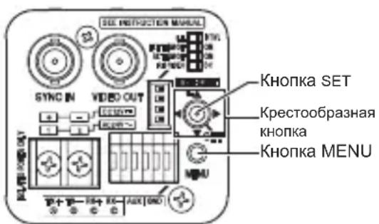
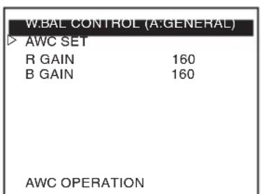
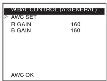
AWC OPERATION AWC OK (Во Врема onepaши) (настоюк заBERш�а)

Стук.typа зараза мени
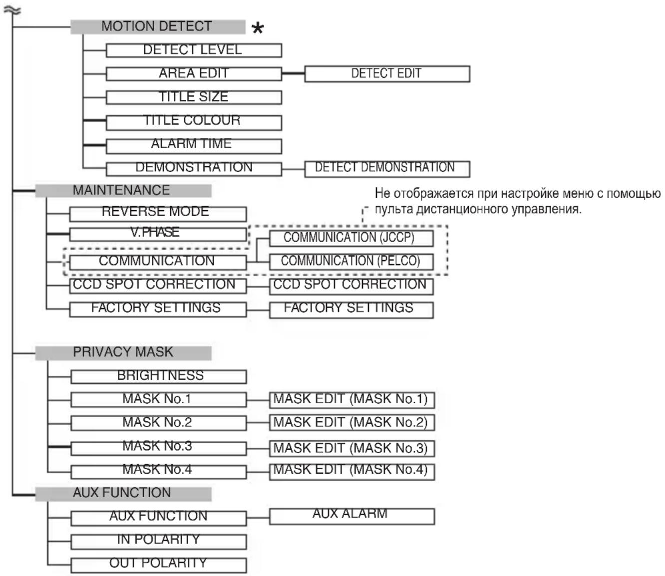
*:NyHKT,KOTOpbI HxHHO HAcTpOBt DnB Bbl6paHHoro aJNa cUeHbI. PpN Heo6xOdMocTn OcyuEcTBnayTe HacTpOy KJKaJDoRo aJNa cUeHbI.
Hactpoika MeHIO
1 HaxmTe KhoNky MENU.
2 IpeBnBte KpecTo06pa3HyIO KHONky BBepx/BHN3, YTO6bl NopabHrTb KypCop () C NyHKTom, KOtOpbI HJXHO HaCTpOHTb.
3 Пере_DиньTe крестообраЗню Кнонку Влебо/ВпразВ,ЧтбИ n3MeHnТь HabТpoйК.
Iocne yctaHOBKn HOBOrO 3HaueHnI NOyBntcR OTMeTka N3MeHeHnR (丰)
4ДлЯ ВьIxOdaи3 HacTppoiKn HaxMnte KhoNky [MENU].
3aMeTkn
Bce paJIbI cUeH mOryT 6bITb n3MeHeHbl. (CTp. 30)
BbI TAKKe MoXeTe NepeKJIIOuHTb 0aJN CcEhbl Ha yCTaHOBJEHbI C NOMOUI BHeUHrO BXoJa. (CtP. 42)
HactpoKa Ha3BaHnI cUeHbI/Ha3BaHnI KaMepbl
BblMOxTe H3MeHnTb Ha3BaHne paJna cUeHbI (do 8 CmBOJOB). Bbl MOxTe Do6aHTb Ha3BaHne KamepbI (do 24 CmBOJOB).
Изменения наразвannahа сцины (SCENE NAME)
"PoKa3aTeJIH ΦaIIIOB cUeH no yMOnuHaHnIO" (cTp. 33)
1 Ha ekpahe [MENU] Bbl6epnte [SCENE FILE] n nepeDbnhte KpecTOO6pa3Hyo KhONky BJIeBO/BnpaBO, yTO6bl Bbl6paTb paJl CueHbl, DnI KOtOporo Bbl XOTnTe yKa3aTb Ha3BaHne.
Повпсг Экран [SCENE FILE].
2 BbI6epnte npHKT [SCENE NAME] ha 3KpaHe [SCENE FILE] n HaxMnte KhoNky [SET].
IopBntcAekpaH [SCENE NAME EDIT]. IepBbI CNMBOJ B CnNcKe CNMBOIOB OTo6paxaETcMnraUoIm. B TaKOM COCTOHN Bbl MoXeTe BBECTN CNMBOJ.
3 IpeBnIbTe KpeCToo6pa3HyIO KHOJky BBepx/BHn3/BJeBO/BnpaBO, YTO6bl BbI6paTb CNMBoJ n3 CnNcKa.
BbIbpaHHbI CNMBOJ HaunHaET MIRaTb.
4 Haxmnte KhoNky [SET].
IodTBePdnte nepBbI CNMBOJ Ha3BaHnI, IV BTOPOI CNMBOJ B O6JaCTN BBeJeHnHa3BaHnI HauchET MmTaTb.
5 Nobtopute 3n 2 n 3.
6 Haxmnte KhoNky [MENU].
Hac troika 6ydet coxpaneha.
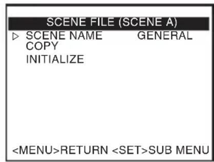
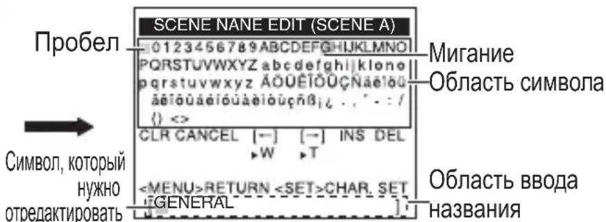
3KpaH [SCENE FILE] 3KpaH [SCENE NAME EDIT]
HactpoJaHa3BaHnI cUeHbI/Ha3BaHnI KaMepbl (npodolxKeHne)
Hac troponka [CAMERA TITLE]
1 Bыберп Te pyнкт [BASIC SETTINGS] Ha ьра He [MENU] n haKMITE KhoNky [SET]. Пявпся кран [BASIC SETTINGS].
2 IpepeBnHbTe KpecToo6pa3HyIO KHOJky BBepx/BHN3, YTO6bl Bbl6paTb [CAMERA TITLE EDIT], n Haxmnte KhoNky [SET].
AWC SET
B GAIN
B GAIN
ÖkpaH [BASIC MENU] ÖkpaH [W. BAL CONTROL]
BbIXoHNo cnHaJ uepHo-6eIoro/ucBeTHoro nepeKJIouaTeJa
CocToHnE 3aIHeRo rHe3da AUX MoKeT 6bITb N3MeHeHO C NOMOuHo CBETHOrO/YePHo-BeNoRo NepeKJIouaTeJRA. TO aKTINBnPoBaHO, KOrDa [AUX FUNCTION] ycTaHOBneHa Ha ,OUT:B&W".
YctaHObka [AUX FUNCTION] Ha ,OUT:B&W"
1 Bыберп Te pyнкт [AUX FUNCTION] ha 3kpahe [MENU] n Haxmnte KhONky [SET].
Повпся зах function].
2Перевиньт ekpecTo06pa3HyO KHONKY BBepx/BHN3,чTO6bI Bbl6paTb [AUX FUNCTION].
3 IpeBnHbTe KpeCTo06pa3HyO KHONky BJeBO/BnpaBO, YTo6bl yctaHOBTb Ha ,OUT:B&W".
4ДлЯ ВьIxOda HaxMnte KhONky [MENU].
Bo3BpaaetKekpaHy [MENU].
![JVC TKC9511EG - YctaHObka [AUX FUNCTION] Ha ,OUT:B&W" - 1](/content/2026/03/516796/images/3210e1386e299a0290970a4e5e5133d1a753269d1ce7b940632870f5acc85b5c.jpg)
![JVC TKC9511EG - YctaHObka [AUX FUNCTION] Ha ,OUT:B&W" - 2](/content/2026/03/516796/images/037ba77c3da219ab0a0276ae7047182a739bbd4bb6f456065f87010b376c8ea6.jpg)
![JVC TKC9511EG - YctaHObka [AUX FUNCTION] Ha ,OUT:B&W" - 3](/content/2026/03/516796/images/bc139d494b81a35689b9e9c4a46f6b7769aac5485c261410f99dd899b2a76ac4.jpg)
∃kpaH [MENU] ∃kpaH [AUX FUNCTION]
YctaHObKa [DAY/NIGHT] Ha „AUTO“
1 Bыберп Te pyнкт [BASIC SETTINGS] Ha зкранe [MENU] n haxmnte KhoNky [SET].
Повпся кран [BASIC SETTINGS].
2ПеревньткрсTo06pa3HyIO KHONky BBepx/BHN3,ЧTO6bI Bbl6paTb [DAY/NIGHT].
3 IpeBnHbTe KpeCToo6pa3HyIO KNONKY BJIeBO/BnpaBO, YTO6bl yCTaHOBTb Ha „AUTO".
![JVC TKC9511EG - YctaHObKa [DAY/NIGHT] Ha „AUTO“ - 1](/content/2026/03/516796/images/3e35bbe6ba760bb7aecd4297070506074e923f71243ad69b246a19aebc0782db.jpg)
ÖkpaH [MENU] ÖkpaH [BASIC SETTINGS]
4ДлЯ ВьIxOda HaxMnte KhoNky [MENU].
Bo3Bpaaet K ekpaHy [MENU].
3aMeTkn
- Доже Когда [AUX FUNCTION] установке на „OUT:B&W“, состорные заимегу гhevда AUX не зменияся, ecn [DAY/NIGHT] на захаре [BASIC SETTINGS] установке на „COLOUR".
Korda nCnoJb3yETcBET 6nHexHrO INHcpaKpachoro Dnana30Ha, n3o6paXeHne MOxET nepeKJIouaTbcra C cepHO-6eIoro Ha cBeTHoe, ecn ECTb CNlbHOe OTPaxeHne OT obekTa. YTo6bl y6eIHTbcra, YTO nepeKJIIOUeHne OcyuieCTBJaTeTcra npaBnIbHO, peKOMeHdyETcRA nCNoJb3OBaTb HAcTPOINky, BHeWHe KOHTPOIpNpyUOyIO nepeKJIIOUeHne C cepHO-6eIoro Ha cBeTHoe n3o6paXeHne.
PpOdoJxKeHne
- 1306paXeHne MoXeT CtaTb paCFOKcNPOBaHHbIM N3-3a pa6Otbl ObBeKTnBa, ecJI NCTOCHNKOM OCBeUeHnYObBeKTA CtaHET CBET 6JIIXHeRo INHΦpaKpachORO Dnana30Ha. B TAKOM Cnyae IcNoIb3yIte ObBeKTNB, NOdIepXnBaIOuSNI CBET 6JIIXHeRo INHΦpaKpachORO Dnana30Ha.
BheuHee ynpaBHeHne cnHaJom YepHo-6eJoro/ucBeTHoro nepeKluOyatela
CnHaJI nepeKIIuOeHn C BHeUHero KOHTpoJIlepa MoKeT 6bITb NCNoIb3OBaH dJa nepeKIIuOeHn I3o6paXeHn Ha Kamepe C ZBeTHoro Ha YepHo-6eIoE n O6paTHO, a TaKKe aKTINBaUcN IOHOBpeMeHHoJ pa6Otbl OCBeUeHn, TaKOrO, KaK CBet 6JInxHero INΦpapacHoro Dnana3OHa.
Для поученя дононтельногинфорmaцио ob yctpoicTBax, KOTOPbie MOxHNo NOdKJIIOuHTb, O6paTntecb K npedCTaBNTeJIHO KOMnaHnJVC.
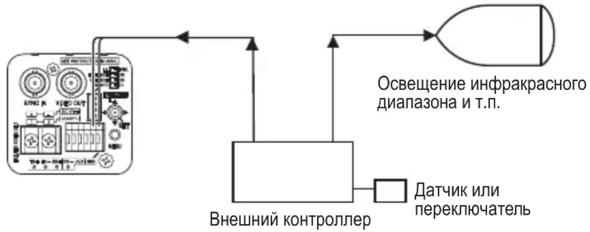
Doctynen fain cunbI dny n3meHnna HactpoeK AGC n SHUTTER npn nepeknoueHn YepHo-6eIoro n CBeTHoro pexima
1 YcTaHOBInTe „SCENE C“ Ha 3Tu HacTpoiKy dIy IcNoIb3OBaHnI dHem (UBeT).
2 YctaHOBInTe „SCENE D“ Ha 3Tu HacTpoiKy dIy IcNoJIb3OBAHnI HoYbIO (YepeHo-6eIoE n3o6paXeHne).
3 YctaHOBnte [SCENE FILE] Ha 3KpaHe [MENU] Ha ,CASINO"(SCENE C).
4 YctaHOBNTe [AUX FUNCTION] Ha 3KpaHe [MENU] Ha ,IN : SCENE D".
Для пооченя божee поюбови Нфорmaци O国有资产Kax CM. [AUX FUNCTION].
3ametkn
B uephno-6eJOM/ucBeTHOM peKnme n3o6paXeHne moKeT CTaTb paocpOKcnpOBaHHbIM n3-3a pa60TbI obBeKTnBa, ecIn nCTOuHNkOM OCBeUeHnA oBeKTA cTaHET CBet 6nnxHero nHcpaKpacHO dnana30Ha. B taKOM cnUyae nCNOJb3yIte OBeKtNB, NOdEprKnBAIOuN CNBET 6nnxHero nHcpaKpacHO dnana30Ha.
Hactpoia cKpbBaHOeMackn
1 Bыберпе пункт [PRIVACY MASK] на захранe [MENU] и нахмITE Кногу [SET]. Повистя захан [PRIVACY MASK].
2 Haxmaite KpecTo06pa3HyO KHONky BBepx/BHN3, YTO6bl BbI6paTb [MASK No.*], 3aTeM BJeBO/BnpaBO, YTO6bl BbI6paTb „ON“, nocne yero Haxmite KhoNky [SET].
Повпся захан [MASK EDIT (MASK No.*)].
3 IcnoIb3yIte KpeCToO6pa3HyIO KNOpKy, YTO6bl OTpeJaKTnPoBaTb JeByHO/BepXHIOI rpaHNU y MaCKN.
4 HaxmTe KhONky [SET].
IoiBntcA 3KpaH n3MeHeHnIpaBOHnXHeN rpaHnCbIMackn.
5 IcnoIb3yIte KpeToO6pa3HyIO KNOpKy, YTO6bl OTpeDaKTnpoBaTb npaByIO/HNXHIOI rpaHnCy MaCKN.
3aMeTKn
HaXMMTe KhoNky [SET], YTO6bI nepeKIOUaTbcra MeJy 3KpaHAMn I3MeHeHnaJIeBOI/BepxHeN IN paBOI/HNXHeI rpaHnC MaCKn.
6 HaxmTe KhoNky [MENU].
HacrpoiKn rpaHnC MaCKn IJIy BbIbpaHHOrO YncJa 6ydyT COxpaHeHbl, nocJe yero 6ydet BO3BpaUeH ekpan [PRIVACY MASK].
7 Повтореши c 2 по 6 по установки BCex Heo6xOДиMbIx MacOK (MASK No.1 до MASK No.4).
8ДЯ ВьIxOda NaЖмITE KHONky [MENU].
Bo3Bpaaet K ekpaHy [MENU].
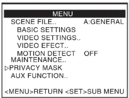
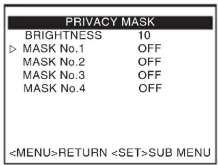
ÖkpaH [MENU] ÖkpaH [PRIVACY MASK]
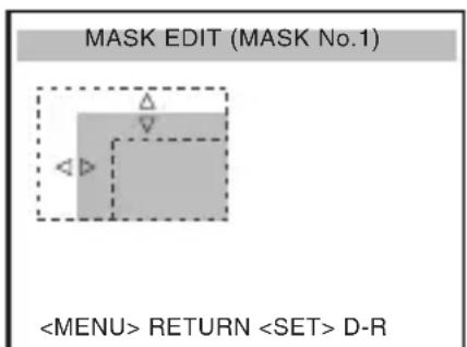
(MASK No.1)

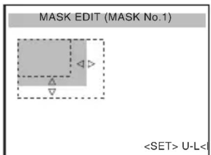
(MASK No.1)
Hactpoia 30hblΦotomeTpnn BLC
Дя Habстpoик Фотометр用电�ь соко oblactи Дя KOMпсаци 3аднoi NOIDCBETKn. Bbl moxe ocuyeCTBNTb habстpoик Ha DByx BnDax ekpaHOB, [EDIT1] n [EDIT2].
1 BbI6epnte npHKT [BLC] Ha 3KpaHe [BASIC SETTINGS] n BbI6epnte [EDIT1].
2 Haxmnte KhoNky [SET].
*Pn nCnoB3OBaHnn yCTaHOBJeHHoJ FOOTOMETpueCKo OBnactu YcTaHOBNTe [BLC]Ha ,EDIT1" uIN ,EDIT2".
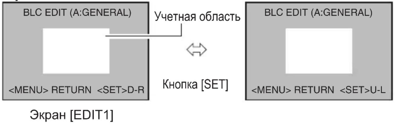
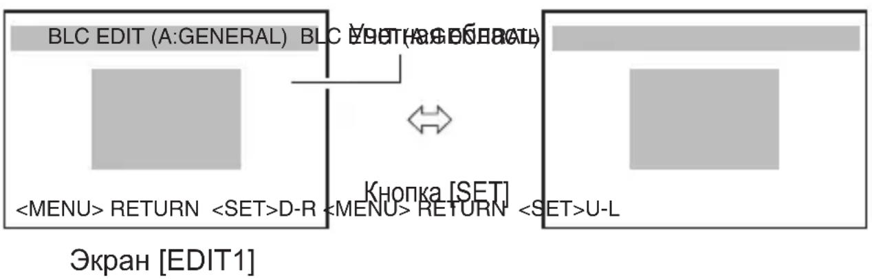
* FOTOMeTpueckne o6nactn dny [EDIT1] n [EDIT2] pa3nHbI.
* PonoJxHHe, OTo6paXeHHoe Ha 3KpaHe, npn6IIN3nteJIbHO.
Поче сбедения
Понск и устараенье несправност
Own6ka npn 3KcPnyatauIN
I3o6paXeHne He oTo6paXaetc.
I3o6paXeHne BbIgJIaNT CMa3aHHbIM.
- PpOBepbTe HnDnKaTOp NITaHnKaMepbl, a TaKKe IODKnIoueH JN DOJXHbIM O6pa3OM KOaKcnaJIbHbI Ka6eJIb.
- Поберът, Habtpoeньл ДОДЖньIM OБра3OMяркoctь И KOHTpact MOHITopa.
- PpOBePbTe, DOCTaToUHa IIN DInHa Ka6eJy.
- PpOBePbTe, npaBnIbHo IIN NOdKJIuOyeH Ka6eJIb O6BeKTiBa C npncobOy DnaΦpaRmoi.
- Пюверьte, настpoeh Ли переключateьВ СоOTВETCTBиC ИСПОЛБ3уEMыМ ОБъektINBOM C aBTOMATUcheCKO ИрсOBОВ Диафparmo. (IRIS VIDEO\L DC)
- ПоберьTe obbeKtNB HaHaJIuYne 3aRpy3HeHn, HApPIMep, rpy3N nIIN nbIIN.
- PpOBepe, npaBnIbHo Jn Hactpoen oKyc.
ctp. 20
ctp. 18
CTp. 18
ctp. 18
ctp. 26
ctp.28