
VN-V685U - Surveillance Camera JVC - Free user manual and instructions
Find the device manual for free VN-V685U JVC in PDF.


| Product Type | Surveillance Camera |
| Brand | JVC |
| Model | VN-V685U |
| Image Sensor | 1/3-inch CCD |
| Resolution | 680 TV lines |
| Lens Type | Varifocal, 2.8-12mm |
| Minimum Illumination | 0.1 lux (color), 0.01 lux (B/W) |
| Day/Night Mode | Yes, with IR cut filter |
| IR Range | Up to 30 meters |
| Video Output | BNC, 1.0Vp-p, 75 ohms |
| Power Supply | 12V DC, 500mA |
| Power Consumption | Max 6W |
| Dimensions (WxHxD) | 130 x 100 x 85 mm |
| Weight | Approx. 400g |
| Housing Material | Aluminum alloy |
| Weatherproof Rating | IP66 |
| Operating Temperature | -10°C to 50°C |
| Mounting Type | Wall or ceiling mount (bracket included) |
| Main Functions | Motion detection, privacy masking, digital zoom, mirror image |
| Maintenance | Clean lens with soft cloth; check connections periodically |
| Safety Certifications | CE, FCC |
| Spare Parts Availability | Power adapter, mounting bracket, IR LEDs |
Frequently Asked Questions - VN-V685U JVC
User questions about VN-V685U JVC
0 question about this device. Answer the ones you know or ask your own.
Ask a new question about this device
Download the instructions for your Surveillance Camera in PDF format for free! Find your manual VN-V685U - JVC and take your electronic device back in hand. On this page are published all the documents necessary for the use of your device. VN-V685U by JVC.
USER MANUAL VN-V685U JVC
VN-V685U/
VN-V686BU

Thank you for purchasing this product.
Before beginning to operate this unit, please read the instruction manual carefully in order to make sure that the best possible performance is obtained.
For Customer Use:
Enter below the Serial No. which is located on the body.
Retain this information for future reference.
Model No. VN-V685U/VN-V686BU/VN-V686WPBU
Serial No.
Safety Precautions

Attention:
This symbol is only valid in the European Union.
Information for Users on Disposal of Old Equipment
[European Union]
This symbol indicates that the electrical and electronic equipment should not be disposed as general household waste at its end-of-life. Instead, the product should be handed over to the applicable collection point for the recycling of electrical and electronic equipment for proper treatment, recovery and recycling in accordance with your national legislation.
By disposing of this product correctly, you will help to conserve natural resources and will help prevent potential negative effects on the environment and human health which could otherwise be caused by inappropriate waste handling of this product. For more information about collection point and recycling of this product, please contact your local municipal office, your household waste disposal service or the shop where you purchased the product.
Penalties may be applicable for incorrect disposal of this waste, in accordance with national legislation.
(Business users)
If you wish to dispose of this product, please visit our web page www.jvc-europe.com to obtain information about the take-back of the product.
[Other Countries outside the European Union]
If you wish to dispose of this product, please do so in accordance with applicable national legislation or other rules in your country for the treatment of old electrical and electronic equipment.
FOR USA AND CANADA

CAUTION
RISK OF ELECTRIC SHOCK DO NOT OPEN

CAUTION: TO REDUCE THE RISK OF ELECTRIC SHOCK. DO NOT REMOVE COVER (OR BACK). NO USER-SERVICEABLE PARTS INSIDE. REFER SERVICING TO QUALIFIED SERVICE PERSONNEL.

The lightning flash wish arrowhead symbol, within an equilateral triangle is intended to alert the user to the presence of uninsulated "dangerous voltage" within the product's enclosure that may be of sufficient magnitude to constitute a risk of electric shock to persons.

The exclamation point within an equilateral triangle is intended to alert the user to the presence of important operating and maintenance (servicing) instructions in the literature accompanying the appliance.
Information for USA
This device complies with part 15 of the FCC Rules. Changes or modifications not approved by JVC could void the user's authority to operate the equipment.
This equipment has been tested and found to comply with the limits for a Class A digital device, pursuant to Part 15 of the FCC Rules. These limits are designed to provide reasonable protection against harmful interference when the equipment is operated in a commercial environment. This equipment generates, uses, and can radiate radio frequency energy and, if not installed and used in accordance with the instruction manual, may cause harmful interference to radio communications. Operation of this equipment in a residential area is likely to cause harmful interference in which case the user will be required to correct the interference at his own expense.
This device complies with Part 15 of the FCC Rules. Operation is subject to the following two conditions: (1) This device may not cause harmful interference, and (2) this device must accept any interference received, including interference that may cause undesired operation.
Due to design modifications, data given in this instruction book are subject to possible change without prior notice.
WARNING: TO REDUCE THE RISK OF FIRE OR ELECTRIC SHOCK, DO NOT EXPOSETHIS APPLIANCE TO RAIN OR MOISTURE.
AVERTISSEMENT: POUR EVITER LES RISQUES D'INCENDIE OU D'ELECTRO- CUTION, NE PAS EXPOSER L'APPAREIL A L'HUMIDITE OU A LA PLUIE.
INFORMATION (FOR CANADA) RENSEIGNEMENT (POUR CANADA)
This Class A digital apparatus complies with Canadian ICES-003.
WARNING (FOR EUROPE):
This is a Class A product. In a domestic environment this product may cause radio interference in which case the user may be required to take adequate measures.
●This installation should be made by a qualified service person and should conform to all local codes.
●This installation shall be in accordance with the National Electrical Code, ANSI/NFPA 70.
●The unit is to be powered by an AC 24 V power supply.
The AC 24 V power supply should conform to the following:Class 2 only(For USA),Isolated power supply only(For Europe and other).
- Any Mention in this manual of Alarm inputs/outputs have not been evaluated by UL to be used for Burglar Alarm Functionality.
FOR USA-California Only
This product contains a CR Coin Cell Lithium Battery which contains Perchlorate Material - special handling may apply.
See
www.dtsc.ca.gov/hazardouswaste/perchlorate
Dear Customer
This apparatus is in conformance with the valid European directives and standards regarding electromagnetic compatibility and electrical safety.
European representative of Victor Company of Japan, Limited is :
JVC Technical Services Europe GmbH
Postfach 10 05 04
61145 Friedberg
Germany
These are general IMPORTANT SAFEGUARDS and certain items may not apply to all appliances.
IMPORTANT SAFEGUARDS
-
Read all of these instructions.
-
Save these instructions for later use.
-
All warnings on the product and in the operating instructions should be adhered to.
-
Unplug this appliance system from the wall outlet before cleaning. Do not use liquid cleaners or aerosol cleaners. Use a damp cloth for cleaning.
-
Do not use attachments not recommended by the appliance manufacturer as they may cause hazards.
-
Do not use this appliance near water - for example, near a bathtub, washbowl, kitchen sink, or laundry tub, in a wet basement, or near a swimming pool, etc.
-
Do not place this appliance on an unstable cart, stand, or table. The appliance may fall, causing serious injury to a child or adult, and serious damage to the appliance. Use only with a cart or stand recommended by the manufacturer, or sold with the appliance. Wall or shelf mounting should follow the manufacturer's instructions, and should use a mounting kit approved by the manufacturer. An appliance and cart combination should be moved with care.
Quick stops, excessive force, and uneven surfaces may cause the appliance and cart combination to overturn.
- Slots and openings in the cabinet and the back or bottom are provided for ventilation, and to insure reliable operation of the appliance and to protect it from overheating, these openings must not be blocked or covered. The openings
PORTABLE CART WARNING (symbol provided by RETAC)

S3125A
should never be blocked by placing the appliance on a bed, sofa, rug, or other similar surface. This appliance should never be placed near or over a radiator or heat register. This appliance should not be placed in a built-in installation such as a bookcase unless proper ventilation is provided.
-
This appliance should be operated only from the type of power source indicated on the marking label. If you are not sure of the type of power supplied to your home, consult your dealer or local power company. For appliance designed to operate from battery power, refer to the operating instructions.
-
For added protection for this product during a lightning storm, or when it is left unattended and unused for long periods of time, unplug it from the wall outlet and disconnect the antenna or cable system. This will prevent damage to the product due to lightning and power-line surges.
-
Do not allow anything to rest on the power cord. Do not locate this appliance where the cord will be abused by persons walking on it.
-
Follow all warnings and instructions marked on the appliance.
-
Do not overload wall outlets and extension cords as this can result in fire or electric shock.
-
Never push objects of any kind into this appliance through cabinet slots as they may touch dangerous voltage points or short out parts that could result in a fire or electric shock. Never spill liquid of any kind on the appliance.
-
Do not attempt to service this appliance yourself as opening or removing covers may expose you to dangerous voltage or other hazards. Refer all servicing to qualified service personnel.
-
Unplug this appliance from the wall outlet and refer servicing to qualified service personnel under the following conditions:
a. When the power cord or plug is damaged or frayed.
b. If liquid has been spilled into the appliance.
c. If the appliance has been exposed to rain or water.
d. If the appliance does not operate normally by following the operating instructions. Adjust only those controls that are covered by the operating instructions as improper adjustment of other controls may result in damage and will often require extensive work by a qualified technician to restore the appliance to normal operation.
e. If the appliance has been dropped or the cabinet has been damaged.
f. When the appliance exhibits a distinct change in performance - this indicates a need for service.
-
When replacement parts are required, be sure the service technician has used replacement parts specified by the manufacturer that have the same characteristics as the original part. Unauthorized substitutions may result in fire, electric shock, or other hazards.
-
Upon completion of any service or repairs to this appliance, ask the service technician to perform routine safety checks to determine that the appliance is in safe operating condition.
Contents
Getting Started
Safety Precautions ......2
Contents ....5
Main Features 6
Safety precautions ....8
Operating Environment 8
Precautions 9
Name and Function of Parts 13
VN-V685U/VN-V686BU 13
VN-V686WPBU 15
Features 16
Connection/Installation (VN-V685U/VN-V686BU)
Mounting the Camera ....18
Power Connection 23
LAN Cable Connection ....24
Connecting the alarm signal terminal .....25
Connection/Installation (VN-V686WPBU)
Mounting the Camera 26
Power Connection 30
LAN Cable Connection ....31
Connecting the alarm signal cable .....32
Network Setting
Network Requirements 33
IP Address Settings 36
IP address setting procedure ....36
IP address setting at the computer .....37
Internet Explorer settings 38
Connecting the camera to the computer .....40
IP address setting for the camera .....42
Enter user name and password .....44
Setting Using Internet Explorer
Setting 46
How to open the setting page 46
Basic Settings1 47
Basic Settings2 48
Camera Page 51
Encoding Page 56
Alarm Page 58
Alarm Environment Page 62
PTZ Page 66
Auto Patrol Page 72
Privacy Mask Page 74
Motion Detection Page 76
Network Basic Page 78
Network Details Page 80
Protocol Page 81
Streaming Page 82
Access Restrictions Page 84
Time Page 86
Password Page 87
Maintenance Page 88
List of Factory Settings of Each Page .....90
Miscellaneous page 94
Operation Page 95
Settings Page 96
Position List Page 99
Patrol Settings Page ....100
Operation
Built-in Viewer 101
Screen Configuration of Built-in Viewer ....102
Image quality setting 104
PTZ Setting 106
PTZ Control 112
JPEG Viewer Settings 117
MPEG4 Viewer Settings ....119
Operator Password 121
Exiting the Viewer ....122
Others
Troubleshooting 123
Specifications 126
Main Features
Support for PoE (Power over Ethernet)
This camera supports PoE (IEEE802.3af) and enables power supply through a LAN cable.
※ Connect to AC 24 V when using the heater. (VN-V686WPBU only)
Dual Stream Full Frame Rate Transmission
Dual stream (JPEG, MPEG4) data transmission is possible in VGA size at a rate of 30 fps.
Realizing a High Picture Quality
This product uses high resolution 380,000 pixels CCD and a new digital image processing IC to achieve high resolution and image quality.
Progressive Output
This function realizes high picture quality of moving objects by fixing combing noise on the contour of the objects.
Long Magnification Zoom Lens
The optical 36 times (VN-V686BU/VN-V686WPBU) and 27 times (VN-V685U) long magnification lenses allow you to conduct detailed monitoring. The high power and large focal ratio F1.6 (WIDE edge) and bright zoom lens realize 1.0 lux (AGC Super, 50 %) high sensitivity during color mode.
Equipped with high precision high speed rotation platform
The newly developed direct drive rotation platform rotates at a high speed of 400% both horizontally and vertically, thus allowing the camera to move to the preset positions quickly. As it does not have a slowdown mechanism, it is very durable, has a high stopping accuracy and can rotate smoothly even at low speed.
Image Stabilizer
This function detects camera shaking and reduces image shaking.
Automatic Tracking function
This product is equipped with a function that easily tracks moving objects when home position is displayed.
Intelligent Tracking Feature
This feature enables you to track color information of the object that you selected by clicking. Linking the zoom feature enables tracking while automatically adjusting to the optimal magnification ratio.
Day/Night surveillance
This product is equipped with infrared filter mechanism for day/night surveillance. During low illuminance such as nighttime, switching out the infrared filter will switch the product to high sensitivity mode (B&W).
Privacy Mask function
This function allows you to blank out areas that you do not wish to display in the location to be recorded.
Motion Detection Feature
This feature enables output of an alarm upon detection of motion in the video image within preset area. Pre-/Post-recorded JPEG image files can be sent to FTP server by the alarm.
Support for Multicast
This product supports multicast, which enables transmission of image data to multiple computers on the network without lowering the frame rate.
Support for IPv6 dual stack
This camera supports IPv6 and enables transition from IPv4.
HTTP-based API
This product comes with HTTP-based API. This feature enables you to perform setting and control via the network.
Built-in Integrated Viewer Software
This product comes with a built-in integrated viewer that enables you to monitor camera images (JPEG or MPEG4) on the computer. It can also be used to configure the camera settings and control the camera. It also employs a new GUI for greater user-friendliness.
Waterproof and Weatherproof Chassis (VN-V686WPBU)
This camera is equipped with a dust-proof and drip-proof mechanism that prevents it from being subject to rain, and therefore can be installed outdoors. (IP66 specification)
*However, VN-V685U/VN-V686BU can only be used indoors. Do not use them in an outdoor environment or expose them to moisture.
This manual contains the detailed instructions for using this unit.
Please refer to [READ ME FIRST] for description on the general usage of this unit.
For the latest information, please refer to the "Readme" file in the CD-ROM supplied with this product.
- The supplied CD-ROM includes INSTRUCTIONS (this manual) (pdf), [API Guide] (pdf), [VSIP Guide] (pdf) and [Search tool].
- Before starting an important recording, be sure to perform a test recording in order to confirm that a normal recording is possible.
- We do not accept liability for the loss of a recording in the case of it becoming impossible to record due to a problem in the video camera, VTR, hard disk recorder or video tape.
- The Automatic Tracking, Intelligent Tracking, and Motion Detection features are simple functions and cannot be used as a substitute for a security alarm. JVC shall not be liable for any inconveniences or damages caused in the event of false detection or when these functions cannot be detected. We shall not be liable for any inconveniences or damages caused as a result of operational failure for alarm input/output.
How to Read this Manual
■ Symbols used in this manual
Note :States precautions to be taken during operation.
Memo :States restrictions on the functions or use of this equipment. For reference purposes.
:Indicates the page numbers or items to refer to.
■ Contents of this manual
- JVC holds the copyright to this manual. Any part or all of this manual may not be reproduced without prior consent from the company.
● Windows is a registered trademark of Microsoft Corporation in the U.S. - Product names of other companies described in this manual are trademarks or registered trademarks of the respective companies. Symbols such as TM , and are omitted in this manual.
- Design, specifications and other contents described in this manual are subject to change for improvements without prior notice.
- Screen displays in this manual may differ from the actual ones.
Safety precautions
Mounting to a firm place
As the unit rotates at high speed, mount it on a firm place with sufficient strength to support the vibration and weight of the unit
Mass:Approx. 1.9 kg (VN-V685U/VN-V686BU)
:Approx. 5.5 kg (VN-V686WPBU)
If the strength is weak, the vibration will cause fuzzy images on the monitor screen. In the worst scenario, the camera may even fall off and hit somebody, resulting in serious accidents.
Mounting the camera correctly with the designated clamping brackets
Always use the designated clamping brackets. Be sure to connect the fall prevention wire and tighten the fixing screws or nuts securely.
Using the correct power and voltage
The rated power of this product is AC 24 V, 50 Hz/60 Hz. Supplying a power beyond the rated value may result in failures and in the worst scenario, smoking and fire.
This unit is able to divert lightning conduction to itself and the connecting cables to a certain extent but this is not 100 % guaranteed. For installation locations that are likely to suffer lightning strikes, be sure to take appropriate measures such as adding arrestor to the connecting cables.
Consult your dealer as special technique is required when installing this product. Ensure that the fixing screws or nuts are tightened securely, otherwise, the unit may fall off.
Inspect the unit regularly.
Screws may be loosened due to vibration or deterioration of the mounting section. Perform regular inspections for loosened screws and check whether there is any danger of the unit falling off.
Do not hang on this product, shake it, or hang objects over it. Applying an excessive load may cause the product to fall off and result in accidents.
Do not modify this product. It may result in accidents.
Operating Environment
Recommended Computer Specifications
OS : Windows XP (Professional or Home Edition) (SP2) :Windows Vista Business (SP1)
CPU : Pentium4 2 GHz or higher
Memory capacity: 1 GB and above
Free hard disk space
:512 MB or more
Display and video card
:1024 × 768 pixels or higher, True
Color (24 bits or 32 bits)
VRAM 8 MB or more (256 MB
and above recommended)
Web browser: Internet Explorer
XP : Version 6.0
Vista : Version 7.0
LAN Environment
●10BASE-T/100BASE-TX network interconnected using devices such as an IEEE802.3-compliant switching hub.
- IEEE802.3af-compliant switching hub when PoE is used
- IGMPv2-compliant network when multicast is in use.
Memo:
●The above PC specifications are guides for smooth use of the applications, and not a guarantee of their operation.
- Depending on the condition of use, applications may not run smoothly even when the user's computer meets the specification requirements.
●The following may occur if the performance of the computer is insufficient.
- Playback frame rate for JPEG images may drop
- Delay in the MPEG4 playback images may occur, and playback is interrupted
- To use MPEG4 images on the integrated viewer, install the open source codec "ffdshow". You can download "ffdshow" from the Internet.
Precautions
Storage and operating environment
● VN-V685U/VN-V686BU is an indoor camera. It cannot be used outdoors.
● VN-V685U/VN-V686BU is a pendant mount camera. Be sure to place the camera head horizontally. The product will not work properly if it is tilted.
● VN-V686WPBU is specially designed to be mounted on walls. Be sure to place the camera head horizontally. The product will not work properly if it is tilted.
- Do not store in the following environments.
It might result in malfunctions or failure.
- Locations beyond the allowable operating humidity range of 20 %RH to 90 %RH. (condensation is not allowed)
- Near equipment that emits strong magnetic fields, such as transformers or motors.
- Near equipment that emits radio waves, such as transceivers and mobile phones.
- Locations with excessive dust and sand.
- Locations that are subject to vibration such as inside the car or ship.
- Locations prone to moisture such as window side.
- Locations subject to steam or oil, such as kitchens.
- Special environment, such as those with combustible atmosphere
- Locations that are subjected to radiation, X-rays, salt attack or corrosive gases.
- Locations where medicine is used such as pools.
● Hot or cold places that are beyond the allowable operating temperature range
■Allowable operating temperature
| VN-V685U/VN-V686BU -10 | °C to 50°C | |
| VN-V686WPBU | ||
| AC 24 V power supply -40 | °C to 50°C | |
| PoE power supply -10 | °C to 50°C | |
- When power is supplied to VN-V686WPBU using PoE, the heater will not work. Use an AC 24 V power supply when using the camera in an environment under -10°C.
- When using VN-V686WPBU in a low temperature environment (-40°C to -20°C), images may not be displayed for up to two hours until the interior is warmed up by the built-in heater. It is therefore recommended that power be supplied to the camera at all times when the surrounding temperature is low. Inadequate heat ventilation may result in malfunction
of this product. Be sure not to block vents around the product. This product discharges heat from the surface of the main unit.
- Do not install it at locations directly subjected to cold air such as near the vents of air-conditioners or at locations with high temperature. Condensation may occur inside the dome cover.
- Use of this product and cables connected to this product at locations where strong electric waves and magnetic waves are generated (e.g., near radio, TV, transformer, monitor, etc.) may cause noise interferences in the images or changes in the color.
Others
- Do not subject the lens to strong light source such as sun rays. This may cause the equipment to malfunction.
● This camera comes with a built-in AGC circuit. The sensitivity increases automatically at a dark place and the screen may appear grainy. This is not a malfunction.
● While AGC is activated, if a transceiver which causes strong electromagnetic wave is used near the camera, the picture may suffer from beat. Please use the camera more than three meters away from such transceivers. - When automatic iris is selected, the Iris Control button may not work depending on the brightness of the screen (when the amount of light is not sufficient). In this case, set the iris to Manual.
- When automatic iris is selected and AGC is ON, even if the iris setting can be changed with the Iris Control button, the Sense Up function will be enabled and the brightness of the screen may not change. In this case, set AGC to OFF or set the iris to Manual.
- When this camera is used in the White Balance "ATW-Narrow", "ATW-Wide" (automatic adjustment) mode, the color tone may differ slightly from the actual color due to the principle of the automatic tracking white balance circuit. This is not a malfunction.
- If a high brightness object (such as a lamp) is shot, the image on the screen may have white vertical tailings. This phenomenon (smear) is characteristic of solid-state image sensors and is not a malfunction.
- Do not touch the dome cover with your hands. Dirty covers will cause image deterioration.
- Do not subject the dome cover to strong impact. It may result in damage and water seepage.
● The dome cover may fog up due to the drastic change of temperature when humidity is high. - Do not connect an AC 24 V cable to AC 110 V/AC 230 V power supply. The camera internal circuit will be damaged. Should that happens, do not use the camera. Bring it to your nearest JVC dealer for repair. (charged separately)
● To supply AC 24 V, use an AC 24 V supplying power unit that is insulated from AC 110 V/AC 230 V line.
Precautions (continued)
Others (continued)
- Depending on the stop position and rotation speed of the horizontal/vertical rotation platform, the running sound of the rotation platforms motor may be heard, but this is not a malfunction.
- When using multicast, make use of a IGMPv2-compliant network switch.
- Some hubs/switches of products that are equipped with intelligent features may include a broadcast/multicast suppression function. Viewing of multicast images on this product may fail if this function is enabled.
● The electronic shutter of this product is set to 1/60 by default. For regions with a commercial power supply frequency of 50 Hz, switch to the 1/100 during use under fluorescent lights (excluding inverter lighting equipment) to prevent flickers. - When the B&W mode is set to “Auto”, the image turns black-and-white in a dark location. As the sensitivity level is increased in this case, the screen may appear grainy and more white spots may appear. When switching between color and black-and-white images, the brighter area on the screen is emphasized, which may reduce the visibility. However, this is not a malfunction.
- If the power supply voltage is momentarily cut off or reduced due to lightning or turning on of the air conditioner's power, the image may be disrupted or noise interference may occur.
- As the dome cover is of a semiglobular shape, image distortion will occur at the hemispherical edge. When the hemispherical edge of this unit is masked and horizontal level is shot in a tilt direction, the hemispherical edge will enter the field angle. This may cause the upper edge of the screen to become black and the focus unclear. In this case, you can avoid shooting the above area by using the tilt limit settings (Page 70).
- When shooting objects with a luminance difference or near a light source, ghost may occur on the screen. This is a feature of the dome cover and the built-in lens, and is not a malfunction.
- In particular, manual and auto pan operation near the TELE edge (telephoto side) may cause the screen to vibrate (unsmooth rotation). This is a feature of the motor and is not a malfunction.
● As long magnification lens is used in this product, the focus may be unclear due to temperature changes but this is not a malfunction. - Preset the focus under an environment with a temperature closest to that in your actual usage. If the temperature change is large and the focus becomes unclear, preset the focus again before using the product.
- If you sense that the focus has become unclear due to temperature changes, use the Auto Foucuα(AF) function or reset the focus manually.
Transporting the unit
- Remove the connecting cables when transporting the unit.
- When transporting the unit, turn off the power of the system.
● Pack the unit with cushioning material so as to avoid shock when transporting.
● Handle the unit with care and do not subject it to vibration or shock.
Copyright Protection
- With the exception of the user being the copyright holder or when permission such as for duplication has been granted by the copyright holder, permission is required in principle for the duplication, modification, or transmission of copyrighted video and audio data. Unauthorized duplication, modification, or transmission of copyrighted material may constitute a copyright infringement, and the user may be liable to compensate for any damages. When using copyrighted video/audio data, be sure to check the license agreement of the copyrighted material thoroughly. When rights or rights holders are involved with regard to the targeted duplicating subject, permission may be required for shooting or using (processing) it. Be sure to check the licensing conditions thoroughly.
Maintenance
● Turn off the power before performing maintenance.
● Wipe using a soft cloth.
Wiping with thinner or benzene may melt or tarnish its surface. For tough stains, wipe using a cloth that is dipped into a neutral detergent diluted with water, followed by wiping with a dry cloth.
- When the same position is monitored for 24 hours continuously over a long period, the increased contact resistance on the horizontal rotation section may cause noise interferences in the images and operation from the computer may become unstable. As such, this product is equipped with an auto cleaning function that performs cleaning once a week.
Saving Energy
- If the camera is not to be used for a long time, turn off the power of the system for safety and energy conservation reasons.
Disclaimer
● The Automatic Tracking, Intelligent Tracking, and Motion Detection features are not features to prevent theft or fire. Our company shall not be liable for any inconveniences or failures that occur.
We shall not be responsible for any inconveniences or disturbances caused in the event of privacy invasion as a result of camera footages of this product.
Transportation
- Do not throw away the original box of the unit. Keep it and use it for transporting the unit in future.
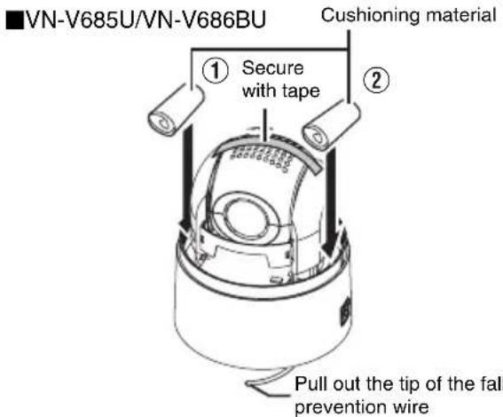
●As the camera unit is of an easily rotatable structure, secure the camera unit inside the dome cover such that it does not rotate before transporting. Otherwise, an error may occur during camera operation.
①Face the heat release vents upward and secure the lens section with tape.
②Insert cushioning material wrapped with air caps (approx. 50 mm x 200 mm) at two opposite sides of the camera.
- When attaching the ceiling clamping bracket to the camera unit before transporting, pull out the tip of the fall prevention wire to prevent it from being caught between the camera and clamping bracket. Otherwise, it may be difficult to detach the bracket from the camera. (VN-V685U/VN-V686BU)

Precautions (continued)
Consumable parts
The following are consumable parts. They must be replaced once they reach their lifetime. The lifetime is only an estimation and differs according to the usage environment and conditions. Replacement of consumable parts is chargeable within the guarantee period.
- Zoom lens assembly
Zoom operation ..... Approx. 2 million operations Focus operation..... Approx. 4 million operations - Slip ring .... Approx. 5 million operations
● Cooling fan .... Approx. 50,000 hours - Heater relay(VN-V686WPBU)...... Approx. 100,000 times
- Heater fan(VN-V686WPBU) .... Approx. 50,000 hours
Auto Focus
This unit is equipped with Auto Focus functions. However, depending on the object and the camera setting, it might be out of focus. In this case, please adjust the focus manually.
- Objects which are difficult to be focused automatically
- When the brightness of the image plane is extremely high (bright)
- When the brightness of the image plane is extremely low (dim)
- When the brightness of the image plane is constantly changing (for example, a blinking light)
●When there is almost no contrast - When there are repetitive vertical striped patterns on the image plane
● Auto Focus is difficult to set under the following conditions - When sensitivity is increased with AGC and the screen is grainy
- When there is less movement on the screen due to the Sense Up function.
- When there is no clear contour in electronic zoom
■ Zoom Operation
The following phenomena are the results of the built-in lens performance and are not malfunctions.
- When manual operation or preset is selected, focus moves slightly after the zoom operation has stopped near the TELE edge.
- Manual zoom operation is not smooth.
- When Preset is selected, the camera becomes out of focus for an instant during zooming.
■ Preset Positions
The total number of preset positions that can be set in this unit is 100, including the home position and 99 preset positions.
Name and Function of Parts
VN-V685U/VN-V686BU
■Ceiling mount section

① Fixing holes (x3)
This hole is for mounting the ceiling clamping bracket to the ceiling or the ceiling recessed bracket (WB-S685: Sold separately).
② [AC24V\~INPUT] AC 24 V Input terminal
This connects the camera to AC 24 V power.
③ [10BASE-T/100BASE-TX] LAN cable connection terminal
This connects the unit to the network.
It supports PoE (IEEE802.3af) and enables you to use this camera without having to connect to a power supply using a power cord.
PoE: class0 ( ☐ Page 24)
4 Alarm input/Alarm output terminal
This terminal is for alarm input/alarm output.
(Page 25)
| Pin number | Signal Name |
| 1 Input 1 | |
| 2 Input 1 | COM |
| 3 Input 2 | |
| 4 Input 2 | COM |
| 5 Output | 1 |
| 6 Output | 1 COM |
| 7 Output | 2 |
| 8 Output | 2 COM |
Reverse side

⑤ Fall prevention wire fixing bracket
This attaches to the fall prevention wire 10 of the camera.
⑥ Wire clamp fixing hole
This is used to bundle wires. (Page 19)
⑦ Fall prevention wire mounting hole
Mount wires from the ceiling slab or channel to this hole to prevent the camera from falling.
8 Power indicator
The indicator lights up in green when AC 24 V power/PoE power is turned on.
⑨ [Mac address] indication
The MAC address is a unique physical address of the product. This address cannot be altered.
⑩ Camera connection terminal (female)
This connects to the connection terminal (male) of the camera.
Name and Function of Parts (continued)
VN-V685U/VN-V686BU (continued)
Camera
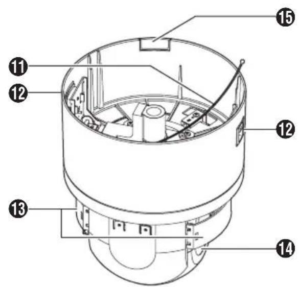

⑪ Fall Prevention Wire
This is fixed to the fall prevention wire fixing bracket ⑤ of the ceiling clamping bracket.
⑫Camera lock knob (x2)
This mounts the camera on the ceiling and secures it so that it does not fall.
13Front Mask
14 Lens
Lens cannot be replaced.
⑮Cable cover
To pull the cables from the side and mount the camera, remove the cover. (Page 20)
⑯Dome Cover
The dome cover is a delicate object. Handle it with care.
Note:
Do not peel off the protective sheet which is attached at shipment, until the dome cover is mounted on the main unit. (Page 21)
VN-V686WPBU
Front side

① Camera securing hole (4 locations)
This hole is used for mounting the camera on the wall.
②Cable connecting hole, cap
Remove the cap and pull out the cables from this hole for connection. ( Page 27)
③Fall Prevention Wire
Connects the camera to the wall. Secure the camera tightly to the anchor bolts used to mount the fall prevention wire on the wall. (Page 28)
④ AC 24 V Power Cable
This connects the camera to AC 24 V power. (Page 30)
⑤Alarm Input/Alarm Output Cable (x8)
This cable is for alarm input and alarm output. ( Page 25)
| Cable color Signal Name | |
| Brown Input 1 | |
| Red Input 1 COM | |
| Orange Input 2 | |
| Yellow Input 2 COM | |
| Green Output 1 | |
| Blue Output 1 COM | |
| Purple Output 2 | |
| Gray Output 2 COM | |

⑥LAN Cable
This connects the unit to the network. ( page 24)
⑦Dome Cover
The dome cover is a delicate object. Handle it with care.
Note:
- It is covered with a protective sheet during shipment. Do not remove this sheet until installation is complete.
⑧Dome Cover Fixing Screws (x4)
⑨Heater ON/OFF Switch
This is the automatic control ON/OFF switch of the built-in heater.
The built-in heater prevents the dome cover from fogging up and snow or frost from attaching to the dome cover. When installing the heater at an unrequired location, turn off the switch of the heater. It is usually set to ON. (Page 26)
10Lens
Lens cannot be replaced.
11Front Mask
⑫[MAC address] indication
The MAC address is a unique physical address of the product. This address cannot be altered.
Features
Surveillance Using Built-in Viewer
This unit comes with a built-in ActiveX JPEG Viewer and MPEG4 Viewer.
JPEG images and MPEG4 images of the camera can be monitored using the computer by installing this Built-in Viewer on the computer.
JPEG images that are currently displayed can also be captured into the computer's hard disk.
"Built-in Viewer" (Page101)
![graph LR A["Camera"] --> B["Z-Square"] B --> C["Network"] C --> D["Computer"]](/content/2026/06/1352302/images/447f4ded3ca8b28ec3a106349263618f7ba85ca075e6cc36a56422cf860da393.jpg)
This unit accepts requests from a maximum of 20 clients.
Monitoring via Multicast
Multicast enables monitoring of JPEG and MPEG4 images on multiple computers.
"Streaming Page" (Page82)
"JPEG Viewer Settings" (Page118)
"MPEG4 Viewer Settings" (Page120)

Simultaneous distribution of JPEG and MPEG4 images enables real-time surveillance using MPEG4 (30 fps) and recording of JPEG images at the same time. You can also lengthen the recording time by lowering the frame rate, resolution, and picture quality settings for JPEG images.
![graph TD A["Camera"] --> B["Network"] B --> C["Computer"] B --> D["Storage Device Recording JPEG"] style A fill:#f9f,stroke:#333 style B fill:#ccf,stroke:#333 style C fill:#cfc,stroke:#333 style D fill:#fcc,stroke:#333](/content/2026/06/1352302/images/563d0669568a29a6b4b571735a817505a9a19d78e44be230cd1e5a6ce538b1d4.jpg)
Saving JPEG images to the FTP server at regular intervals
JPEG images may be uploaded to the FTP server at regular intervals.
"FTP" (Page63)
![graph LR A["camera"] --> B["Network"] B --> C["Computer"] D["Uploads the latest JPEG images to the FTP server at regular"] --> B](/content/2026/06/1352302/images/d9de7cf2d9552418e0c42afd7bbd2f82fe4f42b746e425affacdc5a315b3762e.jpg)
Alarm
This unit comes with a motion detection feature and dual alarm input.
During motion detection or alarm input, actions such as mail delivery, message transmission via TCP/UDP, alarm output, moving to a preset position, and changing of B&W mode settings can be triggered. These actions can also be triggered by combination of two alarm inputs. Installing an FTP server enables uploading of JPEG images before and after the alarm input time (pre-/post-recording) to the server.
"Alarm Page" (Page58)
"JPEG Viewer Settings" (Page118)
![graph TD A["Camera"] --> B["Network"] B --> C["Computer"] D["Alarm Device"] --> B B --> E["Signal Flow"]](/content/2026/06/1352302/images/375c13ef6d5f3890e99d6704df00197d4b7147b39ca0a1af7eab419fc3c78478.jpg)
Sending JPEG images before and after alarm input to FTP
Restrictions on Clients
This unit enables users to authorize or reject the acquisition of images by specific IP address.
Page 84
Control via customized application software
The following uses are also possible by developing a customized application software that supports the API of this unit.
For details, please refer to [API GUIDE] in the supplied CD-ROM.
- Monitors via the computer while at the same time records images to the HDD of the computer.
●Performs recording by changing the frame size/frame rate during alarm occurrence.
●Records the type and time of alarm occurrence on the computer.
Mounting the Camera
Preparation
Be sure to put on protective glasses to protect your eyes from falling objects when mounting the camera.
1 Make holes on the ceiling
- Use the provided template to make a hole (ø80 mm) for the connection cables to thread behind the ceiling.
- If necessary, also open a screw hole to mount the ceiling clamping bracket to the ceiling. In this case, align the “↑ FRONT mark” of the template in the direction where the camera faces front and open the screw hole.
2 Pull the cables from the hole in the ceiling
Pull out the fall prevention wire, power cable, coaxial cable, control signal cable, alarm signal cable and provided alarm cable that were mounted to the ceiling slab from the ceiling.

Note:
- Mount the fall prevention wire on a firm place with sufficient strength.
3 Remove the ceiling clamping bracket from the camera unit
The ceiling clamping bracket is attached to the camera unit during packaging of the product. Before installing the camera, remove the ceiling clamping bracket from the camera unit.
① Check to make sure that the two camera lock knobs (left and right) are unlocked.
- If they are locked, unlock by sliding them in the direction indicated by the arrow.
② Press the two camera lock knobs from both the left and right sides in the direction indicated by the arrows.
- Doing so detaches the ceiling clamping bracket from the camera. Prevent the bracket from dropping such as by performing this on a table.
Memo:
- If the camera fixing lock knob is too stiff, push the knob hard while pressing the edge of the camera unit (A in the diagram) against the table you are using.
③ Lifting the camera unit detaches the ceiling clamping bracket. Remove by sliding it in the direction indicated by the arrows.

4 Remove the terminal cover
Loosen two screws on the ceiling clamping bracket and remove the terminal cover.

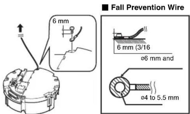
5 Mount the fall prevention wire that connects the ceiling clamping bracket to the ceiling
Caution
- Take note of the length, strength, pull and material (insulation) of the fall prevention wire and use one with a wire strength of more than 20kg.
- The inner diameter of the ring section of the fall prevention wire mounted on the camera should be 4 mm to 5.5 mm and the outer diameter be 9 mm and below.
- The thickness of the screw head and the fall prevention wire (including the washer) should be 6 mm and below. If it is more than 6 mm, the screw will touch the ceiling and the camera cannot be installed horizontally.
- Use M4 fixing screws.
Memo:
●The wire should be insulated from the ceiling structure. If the ceiling structure is metal and insulation is not provided between the camera and the ceiling structure, image noise may occur.
6 Connect the cable (23 to 25)
Connect cables to the terminal of the ceiling clamping bracket.
The connection cables consist of the alarm signal cable, LAN cable and AC 24 V power cable.
① LAN cable (← Page 24)
This connects the unit to the network.
This connects to AC 24 V power.
③Alarm input/output signal terminal (Page 25)
This connects to devices with alarm input/output terminals.

Note:
- Do not connect an AC 24 V cable to AC 110 V power supply. The camera internal circuit will be damaged. Should that happens, do not use the camera. Bring it to your nearest JVC dealer for repair. (charged separately)
- For safety reasons, turn on the power only after all the connection is complete.
●To supply AC 24 V, use an AC 24 V supplying power unit that is insulated from AC 100 V line.
7 Handling cables
Thread the provided wire clamp through the wire clamp fixing hole of the ceiling clamping bracket to tie all the wires.

Note:
- To prevent the cables from tangling and coming off, be sure to thread a wire clamp through the wire clamp fixing hole to tie the cables.
Mounting the Camera (continued)
Preparation (continued)
8 Mount the terminal cover
Return the terminal cover that was removed in step 3 to its original position. The direction to pull out the cables changes according to the mounting method of the camera.
■Pulling out the cables from the side

■Pulling out the cables from the top
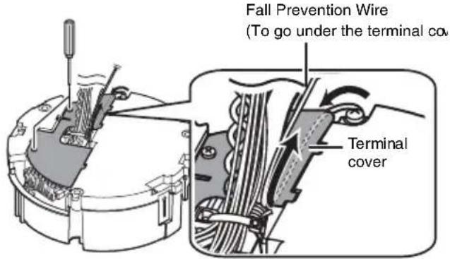
Note:
- Be sure to mount the terminal cover to prevent foreign objects or dust from entering.
- When pulling out the cables from the top, make the fall prevention wire go under the terminal cover and pull it out together with the other cables.
- When pulling out the cables from the side, remove the cable cover of the camera.

Mounting the ceiling clamping bracket to the ceiling
1 Secure the ceiling clamping bracket to the ceiling
- Install such that the “↑FRONT mark” of the ceiling clamping bracket faces the front.
- Ensure that the connection cables are not caught in between and secure the ceiling clamping bracket to the ceiling with 3 screws.

Note:
- Use M4 fixing screws and bolts.
- Use 04.1 wood screws.
● The length of the screws should be 25 mm (1 inch) and above. - Place the product horizontally and install. The camera will not operate properly if it is slanted.
- The screw head should be 5 mm and below. If the ceiling structure is metal, image noise may occur.
- Do not use screws for which the screw head is embedded after fastening. (e.g. flat countersunk head screws). Otherwise, the insulating resin part may be damaged, thus preventing proper insulation.
Memo:
● Always use 3 screws and mount securely.
● Tighten the screws again during maintenance just to be safe.
- The plastic parts on the ceiling fixing holes of the ceiling clamping bracket act as an insulation between the ceiling clamping bracket and the ceiling structure. If the ceiling structure is metal and insulation is not provided between the camera and the ceiling structure, image noise may occur. Be sure to provide insulation.
Mounting the camera to the ceiling
1 Remove the tape on the lens section
2 Remove the lens cap

3 Mount the dome cover to the camera
①Check that the dome cover and lens are free from dirt.
② Turn the dome cover in a clockwise direction to mount.
Note:
- Be sure to turn the dome cover until it stops and tighten securely. Make sure that the dome cover is not slanted.
- Do not over-rotate the dome cover. This may damage the dome cover.
Memo:
- If it is difficult to screw on the dome cover, turn it in an anticlockwise direction until you hear a click sound, then turn it in a clockwise direction. It will screw on smoothly.
4 Remove the dome cover protective sheet

Caution
●The dome cover is an optical part. Handle with care.
- When mounting the dome cover, make sure that there is no dirt inside the cover.
●Tighten the dome cover securely.
Mounting the Camera (continued)
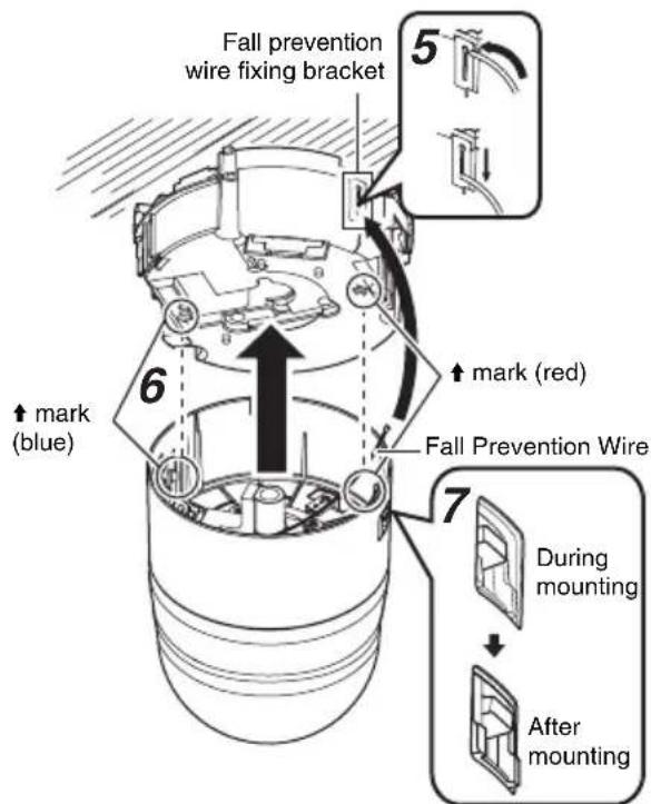
5 Mount the fall prevention wire
Mount the fall prevention wire, which is attached to the camera, to the fall prevention wire fixing bracket of the ceiling clamping bracket.
Caution
- Be sure to connect the fall prevention wire. Otherwise, the camera may fall.
●To prevent danger, do not leave the fall prevention wire dangling by the camera.
6 Mount the camera
- Align the “↑” mark (blue)/(red) inside the camera with the “↑” mark (blue)/(red) on the ceiling clamping bracket.
- Insert the camera into the ceiling clamping bracket until you hear a click sound and mount it securely.
7 Check that the camera fixing lock knobs (x2) are sticking out.
If the camera is mounted on securely, the camera fixing lock knobs (x2) will stick out a little.
Note:
●Before mounting the camera, check that the camera fixing lock knobs are not locked (i.e., lock knobs are on top). The camera cannot be mounted if the lock knobs are locked.
- When pulling out the cables from the side, remove the cable cover of the camera. (Page 18)
8 Lock
When the camera is mounted on the ceiling clamping bracket, lower the camera fixing lock knobs (x2) in the direction of the arrow and secure the camera such that it does not fall off.
9 Remove the safety precautions sheet on the camera
Read through details stated on the safety precautions sheet again.

Caution
- Be sure to check that the camera fixing lock knobs (x2) are locked securely. Otherwise, the camera may fall.
●After mounting, check that the camera is mounted securely. Improper mounting may cause the camera to fall off.
Removing the camera
①Release the lock by sliding the camera fixing lock knobs toward the ceiling.
②Press the two camera fixing lock knobs from both the left and right sides to remove the camera unit.
③Remove the fall prevention wire by performing the mounting procedures in the reverse sequence.
Power Connection
Power can be supplied to this camera either by connecting to an AC 24 V power supply or using PoE (Page 24).
Note:
- If power is supplied from both power cable and LAN cable, priority will be given to the power supply from the power cable.
- Be sure to use an AC 24 V supply that is isolated from the primary power supply circuit. Using a variable voltage power supply will cause the camera and system to malfunction or breakdown.
●The unit is to be powered by an AC 24 V power supply. The AC 24 V power supply should conform to the following: Class 2 only (For USA), Isolated power supply only (For Europe and others).
Connecting to an AC 24 V power supply
This connects the camera to AC 24 V power.

When using 2-core VVF (Vinyl-insulated vinyl-sheath cable), the connection distance is as follows: (Reference value)
| Maximum connection distance | 50 m 15 | 50 m 230 | m 390 m | |
| Conductor Diameter (mm) | ø1.0 and above | ø1.6 and above | ø2.0 and above | ø2.6 and above |
Warning
●The rated power of this product is AC 24 V, 50 Hz/60 Hz. Make sure to use it with the correct voltage.
●Supplying a power beyond the rated value may result in failures, smoke or fire. If the camera breaks down, turn off the power and contact our service center immediately.
- When a power beyond the rated value is supplied, the internal components may be damaged even if no abnormality is found on the appearance and operation of the camera. Please contact your nearest JVC dealer immediately for servicing (charged separately).
Memo:
- After DHCP timeout, all IP addresses of camera are set to 192.168.0.2 by default.
If the power of multiple cameras within the same LAN environment are turned on at the same time, the IP addresses of the cameras overlap, thus preventing proper access. As such, make sure to turn on the power of the cameras one by one. - In a system where multiple units of camera are used, turn on the power of only one unit to configure the IP address settings using the Internet Explorer. Upon doing so, turn on the power of the second unit and configure accordingly. Configure the subsequent camera settings using the same procedure.
- When there is an overlap of IP address, access to the camera may fail. When this occurs, turn on the power of only one camera unit within the same LAN environment and wait for a while (at least 10 minutes). Alternatively, turn off the power of all network devices connected to the same LAN environment, followed by turning them on again.
Note:
- If thin cables are used, the resistance of the cables will be high and a significant voltage drop will occur when the camera is at its maximum power consumption (when pan, tilt and zoom operates at the same time). Either use a thick cable with low resistance or place the power supply near to the camera and shorten the length of the cable to restrict the voltage drop at the rated current of the camera to below 10 %. If voltage drops during operation, the camera may experience unstable performance and be unable to call up the preset position correctly.
- Do not connect an AC 24 V cable to AC 110 V/AC 230 V power supply. The camera internal circuit will be damaged. Should that happens, do not use the camera. Bring it to your nearest JVC dealer for repair. (charged separately)
- Turn on the power only after the connection for all the devices is complete.
- After the power is turned on and activation is completed, this product will move to the home position. The default home position settings for pan, tilt, and zoom are 1.00°, 45°, and x1 respectively.
Power Connection (continued)
Using PoE
Supply power to the camera by connecting it to a device that supports PoE via a LAN cable.
What is PoE (Power over Ethernet)?
PoE is a feature that transfers data and supplies power simultaneously through a LAN cable. It enables you to operate a LAN-compatible equipment without having to connect it to a power supply using a power cord.
Cable to use
●Shield (STP) cable
●Length of 100 m or shorter
●Make use of a Category 5 (or higher) cable.
![[10BASE-T/100BASE-TX] LAN cable connection terminal](/content/2026/06/1352302/images/d71a9ed3101f1e8a77be8cf388c7d0b4971d3202e02cc6af8942933b1353542c.jpg)
LAN Cable Connection
Connect the camera to a hub or computer using a LAN cable.
Cable to use
- Shield (STP) cable
● Length of 100 m or shorter
● Make use of a Category 5 (or higher) cable.
●When connecting to a hub Make use of a straight cable.
- When connecting to a computer Make use of a cross cable.
![[10BASE-T/100BASE-TX] LAN cable connection terminal](/content/2026/06/1352302/images/b7c995b9e10cf9f7467a433893858b0b907c51fb12a9588daf70f61ea4c87243.jpg)
Note:
- However, cross cables cannot be used with some computer models. When connecting this unit directly to a computer, check the computer's LAN specifications in advance.
Connecting the alarm signal terminal
Connect the alarm signal cable to external devices, such as a sensor or buzzer.
Cable to use
●Length of 50 m or shorter
●UL1007, UL1015 or equivalent products
●AWG#22 to AWG#18 or equivalent products
①Loosen screws on both sides of the terminal block with a flathead screwdriver and remove the terminal block as shown in the diagram below.
Memo:
- Inserting the tip of the screwdriver into the slit of the terminal block will remove the terminal block easily.
② Peel off about 4 mm of the alarm signal cable covering and insert into the terminal.
③Turn the screws at the side and secure the alarm signal cable.
④When the alarm signal cable is secured, return the terminal block that was removed in ① to its original position.

Note:
●Noises from an external source may cause the camera to malfunction even when the cable used is within 50 m. In this case, move the cable away from the noise source.
Alarm input signal
Connects to sensors such as infrared sensors, door sensors, metal sensors and manual switches.
- To prevent noise from entering the internal circuit, supply non-voltage contact signal to the alarm input signal.
- Do not supply voltage.
- When the contact is short (MAKE) or open (BREAK) on the menu, you can set it to Alarm.
●Supply such that the alarm signal continues for at least more than 500 ms. The alarm signal may not be recognized if it is less than 500 ms.

Alarm output signal
Connect to alarm devices such as alarm, indicator, light or buzzer.
- Alarm output signal is an open collector output insulated with photo coupler.
• During an alarm, it is ON. - As this terminal is polarized, be sure to connect it such that the voltage of the + output is higher than that of the - output.
- It will be damaged if reverse voltage is supplied.

Rating:
Max. applied voltage: DC 20 V
Max. driving current: 25 mA
Mounting the Camera
Setting Up the Wall
Be sure to put on protective glasses to protect your eyes from falling objects when mounting the camera.
1 Make holes in the wall
Make holes ( 45 mm) for the connecting cables to pass through.
Note:
- Check the strength of the wall. A less firm wall may cause the unit to fall.
2 Install the anchor bolts for mounting the camera
Install 4 anchor bolts (M8 × 35 mm and above) to mount the camera.
3 Install the anchor bolt for mounting the fall prevention wire
Install the anchor bolt (M8 × 35 mm and above) to mount the fall prevention wire 30 mm below the center of the upper two anchor bolts that are used to mount the camera.

4 Pull the cables from the hole in the wall
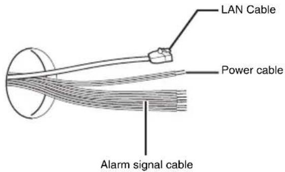
Pull the power cable, LAN cable and alarm signal cable from the wall.
Setting Up the Camera
1 Remove the dome cover
Loosen the screws (x4) and remove the dome cover from the camera.

2 Remove the cushioning material, lens cap and tape used during transporting
When installing the heater at an unrequired location, turn off the switch of the heater.

3 Insert silica gel (when using PoE power supply)
Note:
- Be sure to insert the provided silica gel in the position as shown in the diagram when using the PoE power supply. Otherwise, the camera lens may fog up or the image may become blur.
① Remove the screw and lift up the plate
②Take out 3 silica gels from the aluminum bag and insert them into the position as shown in the diagram.
③Fasten the screw

Memo:
●During reconnection or re-installation after repair or maintenance, make sure to replace the silica gel with a new one.
- Consult your nearby JVCfs dealer on the replacement procedures.Serial number of part to be replaced: Use a LW40500-001A silica gel.
Note:
- When mounting is performed on a rainy day, make sure that rain water does not enter this unit.
4 Mount the dome cover to the camera
Use the screws (x4) to mount the dome cover to the camera. As a guide, install the three catches of the dome cover and the central mark. Install such that the central mark appears above the JVC mark of the camera.

Note:
- Check that there is no dirt or dust inside the dome cover before mounting.
- When installing on a rainy day, ensure that raindrops do not enter the interior.
- When mounting the dome cover, temporarily secure the 4 screws and then tighten.
- As a guide, tighten the screws to 0.5 N•m to 1 N•m (5 kgf•cm to 10 kgf•cm). If the tightening is loose, the dome cover may fog due to water seepage.
5 Remove the cable connection cap
Remove the cap on the arm of the camera.
6 Pull out the cables from the cable connection hole
Pull out the cables (except the fall prevention wire) of the camera from the cable connection hole.

Mounting the Camera (continued)
Mounting the Camera
1 Mount the fall prevention wire
- Mount the fall prevention wire of the camera to the fall prevention wire anchor bolt that was installed earlier.
- Secure the fall prevention wire tightly with a nut and washer.
2 Pull out the cables (from the wall) from the cable connection hole.
3 Mount the camera to the wall
- Mount the camera to the camera anchor bolts that were installed earlier.
- Secure the camera tightly with a nut and washer.

Note:
- This product weighs approximately 5.5kg. When installing, pay extra attention as it may fall.
- For your safety, hold the arm section during installation.
● After installing, paint the nuts and washers to prevent corrosion.
Memo:
- To remove the camera, follow the reverse procedures.
Cable Connection
1 Connecting the power cable (Page 30)
Connect the power cable and wind the waterproof tape (adhesive).
After connecting, push the cable into the arm of the camera.

2 LAN Cable Connection (Page 31)
①Use the provided RJ-45 conversion connector and connect the LAN cable.
②Wind the connector section with waterproof tape (adhesive) and push the cable into the arm of the camera.

3 Connecting the alarm cable (Page 25)
Connect the alarm cable and wind the waterproof tape (adhesive).
After connecting, push the cable into the arm of the camera.

Note:
- For cables that are not used, be sure to wrap the ends individually with insulating tape.
- For safety reasons, turn on the power only after all the connection is complete.
4 Mount the cap
5 Seal the cable connection hole and around the mounting surface of the camera with waterproof seal (GE silicon).

Note:
- Ensure that waterproof treatment is performed. Otherwise, the camera may malfunction due to rain water seepage.
- Use GE silicon or other similar product for the sealing material.
6 Remove the dome cover protective sheet

Power Connection
Power can be supplied to this camera either by connecting to an AC 24 V power supply or using PoE (Page 31).
Note:
- If power is supplied from both power cable and LAN cable, priority will be given to the power supply from the power cable.
- Be sure to use an AC 24 V supply that is isolated from the primary power supply circuit. Using a variable voltage power supply will cause the camera and system to malfunction or breakdown.
●The unit is to be powered by an AC 24 V power supply. The AC 24 V power supply should conform to the following: Class 2 only (For USA), Isolated power supply only (For Europe and others).
Connecting the power cable
This connects the camera to AC 24 V power.

When using 2-core VVF (Vinyl-insulated vinyl-sheath cable), the connection distance is as follows: (Reference value)
| Maximum connection distance | 30 m 80 | m 120 m | m 210 m | |
| Conductor Diameter (mm) | ø1.0 and above | ø1.6 and above | ø2.0 and above | ø2.6 and above |
Warning
●The rated power of this product is AC 24 V, 50 Hz/60 Hz. Make sure to use it with the correct voltage.
●Supplying a power beyond the rated value may result in failures, smoke or fire. If the camera breaks down, turn off the power and contact our service center immediately.
- When a power beyond the rated value is supplied, the internal components may be damaged even if no abnormality is found on the appearance and operation of the camera. Please contact your nearest JVC dealer immediately for servicing (charged separately).
Memo:
- After DHCP timeout, all IP addresses of camera are set to 192.168.0.2 by default.
If the power of multiple cameras within the same LAN environment are turned on at the same time, the IP addresses of the cameras overlap, thus preventing proper access. As such, make sure to turn on the power of the cameras one by one. - In a system where multiple units of camera are used, turn on the power of only one unit to configure the IP address settings using the Internet Explorer. Upon doing so, turn on the power of the second unit and configure accordingly. Configure the subsequent camera settings using the same procedure.
- When overlapping of the IP address occurs, check to ensure that there is only one camera unit within the same LAN environment, and wait for a while (at least 10 minutes) or power off and on all network devices under the same LAN environment. Otherwise, access to the camera may fail.
Note:
- If thin cables are used, the resistance of the cables will be high and a significant voltage drop will occur when the camera is at its maximum power consumption (when pan, tilt and zoom operates at the same time). Either use a thick cable with low resistance or place the power supply near to the camera and shorten the length of the cable to restrict the voltage drop at the rated current of the camera to below 10 %. If voltage drops during operation, the camera may experience unstable performance and be unable to call up the preset position correctly.
- Do not connect an AC 24 V cable to AC 110 V/AC 230 V power supply. The camera internal circuit will be damaged.
- Should that happens, do not use the camera. Bring it to your nearest JVC dealer for repair.
- Turn on the power only after the connection for all the devices is complete.
● After the power is turned on and activation is completed, this product will move to the home position.
Using PoE
Supply power to the camera by connecting it to a device that supports PoE via a LAN cable.
What is PoE (Power over Ethernet)?
PoE is a feature that transfers data and supplies power simultaneously through a LAN cable. It enables you to operate a LAN-compatible equipment without having to connect it to a power supply using a power cord.
Cable to use
●Shield (STP) cable
●Length of 100 m or shorter
●Make use of a Category 5 (or higher) cable.
Note:
- When power is supplied to VN-V686WPBU using PoE, the heater will not work. Use an AC 24 V power supply when using the camera in an environment under -10°C.

LAN Cable Connection
Connect the camera to a hub or computer using a LAN cable.
Cable to use
- Shield (STP) cable
● Length of 100 m or shorter
● Make use of a Category 5 (or higher) cable.
●When connecting to a hub Make use of a straight cable.
●When connecting to a computer Make use of a cross cable.

Note:
- However, cross cables cannot be used with some computer models. When connecting the camera directly to a computer, check the computer's LAN specifications in advance.
Connecting the alarm signal cable
Connect the alarm signal cable to external devices, such as a sensor or buzzer.
Cable to use
●Length of 50 m or shorter
- UL1007, UL1015 or equivalent products
●AWG#22 to AWG#18 or equivalent products

Note:
●Noises from an external source may cause the camera to malfunction even when the cable used is within 50 m. In this case, move the cable away from the noise source.
Alarm input signal
Connects to sensors such as infrared sensors, door sensors, metal sensors and manual switches.
- To prevent noise from entering the internal circuit, supply non-voltage contact signal to the alarm input signal.
- Do not supply voltage.
- When the contact is short (MAKE) or open (BREAK) on the menu, you can set it to Alarm.
●Supply such that the alarm signal continues for at least more than 500 ms. The alarm signal may not be recognized if it is less than 500 ms.

Alarm output signal
Connect to alarm devices such as alarm, indicator, light or buzzer.
- Alarm output signal is an open collector output insulated with photo coupler.
• During an alarm, it is ON. - As this terminal is polarized, be sure to connect it such that the voltage of the + output is higher than that of the - output.
- It will be damaged if reverse voltage is supplied.

Rating:
Max. applied voltage: DC 20 V
Max. driving current: 25 mA
Network Requirements
- Ensure that there is sufficient network bandwidth for the data volume to be sent out by the camera. Do not send multicast stream that exceeds the bandwidth. If the entire bandwidth is used by the multicast stream, control of this camera via the network may fail.
●Data volume to be sent by the camera varies with the settings and number of distributions.
●The maximum bit rate for transmission is about 20 Mbps.
Estimation of Total Bit Rate
The total JPEG bit rate from the camera is determined by the camera settings, number of clients, and the client's requested number of frames. The total MPEG4 bit rate from the camera is determined by the number of distributions. Develop a design upon taking the above into consideration.
Bit Rate of JPEG Stream
The JPEG file size per frame varies with the encoding settings as well as input video signals. The following table may be used as a reference.
■AFS (Average File Size)
When AFS is selected, encoding will be performed such that the target file size is the average size of multiple JPEG images.
| Selectable between 10 KB to 100 KB | Selectable between 3 KB to 33 KB |
■VFS(Variable File Size)
When VFS is selected, the quantization table during JPEG encoding will be maintained, and the file size will increase/decrease according to the input signals.
The maximum number of distributions varies with the bit rate settings as well as the client's requested frame rate. Up to 20 streams can be distributed (including multicast). The total frame rate refers to the sum of these frame rates. For example, when 10 fps is requested by two clients, and in addition, multicast is transmitted at a rate of 10 fps, the total frame rate will be:
1 0 + 1 0 + 1 0 = 3 0 fps
If the JPEG file size per frame is 30 KB, then the total bit rate will be:
3 0 KB × 3 0 fps = 9 0 0 KB/s = Approx. 7. 2 Mbps
Network Requirements (continued)
Bit Rate of MPEG4 Stream
You can select either the Variable Bit Rate (VBR) or Constant Bit Rate (CBR) system for MPEG4 stream. When the VBR system is selected, the bit rate varies according to the condition of the input video signals. The VBR system delivers a stable picture quality, but forecast of the bit rate is difficult. When the CBR system is selected, encoding is performed at a fixed bit rate regardless of the condition of the input video signals. The picture quality varies under the CBR system, but the bit rate can be easily forecast. You can specify an estimated bit rate for both VBR and CBR. (64 kbps to 8000 kbps)
Restrictions on the Number of Distributions for Camera
The maximum number of distributions for this unit is determined by the settings as well as requirements from the client.
When only JPEG images are distributed, the maximum number of distributions is determined based on the highest bit rate within the stream. When a distribution request that exceeds the maximum number of distributions is received, this request is denied. For example, if Client A requests for and receives data at 1 Mbps, while Client B requests for and receives data at 5 Mbps, the maximum number of distributions is 4 streams according to the table below.
Maximum number of distributions when only JPEG data is distributed
| Distribution at maximum bit rate | Maximum number of distributions | Total maximum bit rate |
| 1 Mbps and below | 20 20 Mbps | |
| 5 Mbps and below | 4 20 Mbps | |
| 10 Mbps and below | 2 20 Mbps | |
| Larger than 10 Mbps | 1 Maximum configurable value (24 Mbps) |
When only MPEG4 images are distributed, the maximum number of distributions is determined by the preset bit rate. When a distribution request that exceeds the maximum number of distributions is received, this request is denied.
When distributing only MPEG4 data
| Preset bit rate | Maximum number of distributions | Total maximum bit rate |
| 0.6 Mbps and below | 20 12 Mbps | |
| 3 Mbps and below | 4 12 Mbps | |
| 6 Mbps and below | 2 12 Mbps | |
| Larger than 6 Mbps | 1 Maximum configurable value (8 Mbps) |
When both JPEG and MPEG4 images are distributed simultaneously, distribution up to two clients for JPEG and MPEG4 respectively is possible. However, distribution requests that exceed a total bit rate of 20 Mbps will be denied.
| Total bit rate | Maximum number of distributions for JPEG | Maximum number of distributions for MPEG4 |
| 20 Mbps and below | 2 | 2 |
Insufficient network bandwidth
When there is insufficient bandwidth, the number of JPEG frames (frame rate) that the client can acquire will decrease. Delay will also occur in the distribution of images. In the case of MPEG4, noise interference may occur and playback may fail.
Network Delay
When the client acquires JPEG via TCP, the camera will send out data while checking the ACK from the client at the same time. For networks with considerable delay, data cannot be sent out until ACK is received, and therefore the frame rate will drop. In the case of MPEG4, noise interference may occur and playback may fail.
Decrease in the frame rate due to network delays can be eliminated by receiving data via multicast.
Network Jitter
When there is considerable network jitter, delay time may be prolonged and the image frame rate may drop. In the case of MPEG4, noise interference may occur and playback may fail.
Packet Loss
When acquiring images from this unit via TCP, packet loss may be recovered by TCP retransmission. When there is considerable delay in the network, however, missing data may occur and the image frame rate may drop. In the case of MPEG4, noise interference may occur and playback may fail.
When packet loss occurs during multicast sending from this unit, the image frame rate may drop. In the case of MPEG4, noise interference may occur and playback may fail.
List of Protocols and Port Numbers Used by this unit
This unit uses the protocols and port numbers listed below. Ensure that these ports are allowed through the firewall when a firewall is to be installed.
| Protocol/Port No. | Purpose of Use |
| Source | |
| TCP/80 JPEG/MPEG | G4 server,Web Settings page, API |
| TCP/5510 VSIP | |
| TCP/10020 TCP/10021 TCP/10023 | (Reserved for adjustment) |
| TCP/32040 Alarm Server | |
| Destination | |
| TCP/20, 21 FTP | |
| TCP/25 Mail delivery | |
| TCP/110 POP (Mail) | Delivery) |
| TCP/User Setting No. | Sending alarm |
| UDP/123 SNTP | |
| UDP/5510 VSIP | |
| UDP/9541 VSIP discovery protocol | |
| UDP/User Setting No. | Sending alarm |
IP Address Settings
IP address setting procedure
Follow the procedure below to configure the IP address of the camera.
Step1 IP address setting at the computer (Pager37)
Set the IP address of the computer for configuring the camera settings.

Step2 Internet Explorer settings (Pager38)
Configure the Internet Explorer settings in order to establish connection between the computer and the camera.

Step3 Connecting the camera to the computer (¶Pager40)
Connect the computer to the camera.

Step4 IP address setting for the camera (Pager42)
Set the [DHCP Disable] item on the [Basic Settings1] screen to "DHCP Enable" or "DHCP Enable".
●System configuration required for setting IP address
Camera at factory default is set to “DHCP Enable” (DHCP client function is On). When it is connected to a LAN without DHCP servers, it will activate under the following IP address after timeout.
IP address : 192.168.0.2
Subnet mask : 255.255.255.0
Default gateway
: None
Memo:
- To set a static IP address for the camera, connect the camera, the switching hub and the computer for setting using a straight LAN cable of Category 5 and above.
- Set up the computer for setting the IP address.
●Minimum computer specifications for setting
OS : Windows XP (Professional or
Home Edition) (SP2)
Web browser
: Internet Explorer Version 6.0
Note:
- When setting the IP address of the camera, do so by using a network that is made up of only the camera, the computer for setting and the switching hub.
- Using a hub connected to other network devices or networks via a LAN cable for setting can cause problems.
IP address setting at the computer
Set the computer to an IP address that enables communication with the camera.
1 Click [Start]
- Select in the sequence of [Control Panel]–[Network Connection]–[Local Area].
Windows Vista:
- Select in the sequence of [Settings]- [Control Panel]- [Network Center]- [Network Connection].
2 The computer on which Internet Explorer is launched automatically selects the connected network
● Right-click and select [Properties].
- Check to ensure that the [Client for Microsoft Networks] and [Internet Protocol(TCP/IP)] check boxes are selected.
Windows Vista:
- Check to ensure that the [Client for Microsoft Networks] and [Internet Protocol Version 4 (TCP/IPv4)] check boxes are selected.
3 Select [Internet Protocol(TCP/IP)] and click [Properties]
Windows Vista:
- Select [Internet Protocol Version 4 (TCP/IPv4)] and click [Properties].
4 Set the IP address

5 Click [OK] on the [Local Area Connection Propertise] screen
IP Address Settings (continued)
Internet Explorer settings
1 Launch the Internet Explorer on the computer
2 When proxy settings are enabled in the Internet Explorer, follow the steps below to disable the proxy of the Internet Explorer
- Select in the order of [Tool]–[Internet Options]–[Connections]–[LAN Setting], followed by deselecting the check for [Use a proxy server for your LAN] under [Proxy Server] of the [Local Area Network (LAN) Settings] window.
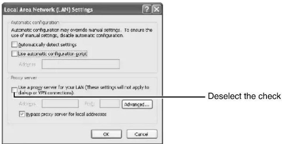
3 If the active script of the Internet Explorer is disabled, follow the steps below to enable it
- Select [Trusted sites] under [Tool]—[Internet Options]—[Security]. Upon doing so, the [Sites...] button directly below becomes active. Click this button and deselect the check [in the displayed window], and add the following web site to the zone.
http://192.168.0.2
- Next, select [Trusted sites] under [Tool]–[Internet Options]–[Security], and press the [Custom Level] button. Select [Enable] under [Scripting]–[Active script] of the [Security Settings] window that has been opened.
![Security Settings Settings: Scriting Active scripting Disable Enable Prompt Allow paste operations via script Disable Enable Prompt Scripting of Java applets Disable Enable Prompt Reset custom settings Reset to: Medium Reset OK Cancel Select [Enable]](/content/2026/06/1352302/images/16878e832d22a9713f4367156e886280d2159ae2a88ea3356fb52511535ec348.jpg)
4 If ActiveX controls and plug-ins of the Internet Explorer is disabled, follow the steps below to enable it
- Click [Trusted sites] under [Tool]—[Internet Options]—[Security]. Select the [Custom Level] button and open the [Security Settings] window. Set all items under [ActiveX controls and plug-ins] in the opened window to [Enable]. Enable also [Use the following IP address] under [Miscellaneous].
![Security Settings Settings: ActiveX controls and plug-ins Automatic prompting for ActiveX controls Disable Enable Binary and script behaviors Administrator approved Disable Enable Download signed ActiveX controls Disable Enable Prompt Download unsigned ActiveX controls Disable Select [Enable] Reset…](/content/2026/06/1352302/images/87c35c6c430ba74551c87e8d947ccc5c33483c70e3a85879f8250dc08f85b62d.jpg)
5 Disable pop-up block
Connection of the camera cannot be established when pop-up block in the Internet Explorer is set to "Enable".
Follow the steps below to set the pop-up block to "disable".
- Selecting [Tool]—[Pop-up Blocker]—[Turn Off Pop-up Blocker] permits all sites.
- To allow only specific sites such as this unit, select [Tool]–[Pop-up Blocker]–[Turn On Pop-up Blocker], followed by selecting [Tool]–[Pop-up Blocker]–[Pop-up Blocker Settings] that becomes active to open the [Pop-up Blocker Settings] window.
In the opened window, add the address of VN-V686BU as a permitted web site address.
6 If plug-in tools are installed in the Internet Explorer, disable the pop-up block function of these plug-in tools as well.
Connecting the camera to the computer
IP Address Settings (continued)
1 Launch the Internet Explorer
![①Enter the following IP address into the address field. http://192.168.0.2 ② Click [Go]. about:blank - Microsoft Internet Explorer File Edit View Favorites Tools Help Back Search Favorites Go Links Address http://192.168.0.2](/content/2026/06/1352302/images/d6623b9c00ff1501f291057099e44951acddc9e197f60263d91c72077bd6fa94.jpg)
Memo:
- If the proxy server settings for access to the Internet via the Internet Explorer is enabled, you may not be able to specify the IP address directly. In this case, change the proxy settings of the Internet Explorer.
- After the [Security Settings] screen appears, press the [OK] button to proceed.
■When the IP address of the camera is unknown
IP address settings cannot be changed by accessing via a computer when the IP address of the camera is unknown. You can use the following method to identify the IP address.
- Search for the camera in the LAN using [Search tool] inside [Tool_E] folder of the supplied CD-ROM.
For details on [Search tool], please refer to the "Readme" file in the CD-ROM supplied with this product.
2 Enter the user name and password (login as administrator) (Page 44)
![Connect to 192.168.0.2 User name: Password: Remember my password OK Cancel ① Enter the user name. This is set to "admin" by default. ② Enter the password. This is set to "jvc" by default. ③ Click [OK].](/content/2026/06/1352302/images/8426cdcd40db8edfe48409214ab03eaafff4c6fb2b6c07ff038a3e37e1217edf.jpg)
Memo:
- After the [Security Settings] screen appears, press the [Yes] button to proceed.
3 Built-in Viewer appears

4 The Operator Password entry screen appears
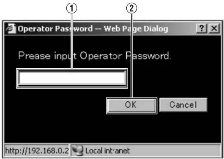
① Operator Password (default password is "jvc")
②Click [OK].
Memo:
- The operator password entry screen does not appear if the password is stored on the computer. Proceed to configure the IP address. (Page 42)
IP Address Settings (continued)
IP address setting for the camera
1 Click [Advanced Settings] of the Built-in Viewer
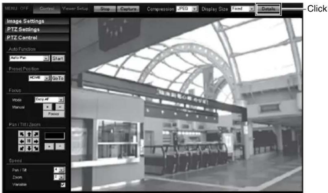
2 The [Basic Settings1] screen appears

①Specify the [DHCP Disable].
- When selecting "DHCP Enable":
The default setting is “DHCP Enable” (DHCP client function is Enabled). To assign an IP address from the DHCP server, connect the DHCP server to the LAN, set the [DHCP Disable] of the camera to “DHCP Enable”, and click the [OK] button. For details on IP addresses assigned to the camera, consult your network administrator. - When selecting "DHCP Enable":
Select "DHCP Enable", and specify a value in the [IP address], [Subnet Mask] and [Default Gateway] fields.
Note:
- Set the DHCP server such that the same IP address is always assigned to the MAC address of the camera by the DHCP server. Connection may fail if the above setting is not performed.
②Specify the [Time Zone].
③Click [OK].
3 A confirmation screen appears
Click [OK].
Camera restarts using the new IP address. It takes about one minute for the camera to reboot.
Memo:
- Access from this computer may fail when the IP address of the camera is changed. To enable access to this unit from the same computer, alter the IP address at the computer accordingly.
When the display or configuration of the opened screen appears strange, check the computer settings using the following procedures.
① Click [Start]–[Control Panel]–[Display] and open the [Display Properties] window
② Click the [Settings] tab in the [Display Properties] window and click the [Advanced] button
③ Check that [DPI setting] in the [General] tab has become [Normal size(96DPI)]
④Otherwise, change the setting to [Normal size(96DPI)] and reboot Windows
IP Address Settings (continued)
Enter user name and password
User name and password entry will be required at the beginning.( page 40)
There are three access authorization levels to the camera. The factory settings are as follows.
| User Name | Default Password | Description |
| admin jvc | All operations and setting changes are allowed | |
| operator jvc | Change of settings other than those related to network and maintenance are allowed | |
| user jvc | Viewing of images is allowed |
●Pages that users have access to
Restrictions are placed on the pages that users have access to. In addition, links on the web pages are also displayed according to the access rights of the user.
- admin
| Basic Settings1 [Network][Time] |
| Basic Settings2 [Camera][Encoding][JPEG][MPEG4] |
| Detalis [Camera] |
- operator
| Basic Settings2 [Camera][Encoding][JPEG][MPEG4] |
| Detalis [Camera] |
- user
Detalis [Miscellaneous]
Memo:
●Security Information window may appear before the top page is displayed. Press the [OK] button to proceed.
If you do not want this warning screen to be displayed, change the Internet Explorer settings as follows.
- Open [Tool]–[Internet Options]–[Security] and select the [Trusted sites] icon.
- Next, press the [Custom Level] button, followed by selecting “Enable” for [Miscellaneous]–[Display mixed content].
Note:
- Do not reset or turn off the power of camera immediately after the settings are changed. Otherwise, changes may not be saved or may be saved incorrectly.
- If settings are changed when sending JPEG or MPEG4, the transmission may be temporarily cancelled.
Setting
How to open the setting page
1 Enter the IP address of the camera in the address bar of Internet Explorer (Page 40)
●A Built-in Viewer is opened.

2 Click [Detalis]
- [Basic Settings1] page will be opened if accessed by user name "admin". (Page 47)
- [Basic Settings2] page will be opened if accessed by user name "operator". (Page 48)
- [Miscellaneous] page will be opened if accessed by user name "user". (Page 94)
Basic Settings1
This page is for performing basic setting related to the network.
- This page can be used during access using “admin”.
- Click [Basic Settings1].
- Press the [OK] button to enable the new settings.
- If the [OK] button is pressed upon entering an invalid value, a warning message will appear and the entry will be denied. Press the [Cancel] button to restore the invalid entry to the current value.
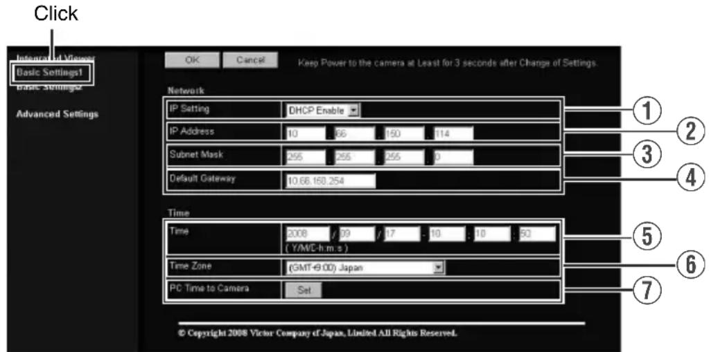
Memo:
- You can open the [Basic Settings1] screen without going through Built-in Viewer by entering direct URL address in the address field of Internet Explorer.
When the IP address of the camera is 192.168.0.2 for example, enter the URL below.
VN-V685U :http://192.168.0.2/cgi-bin/v685display.cgi?v685basicmenu1.html
VN-V686BU/VN-V686WPBU :http://192.168.0.2/cgi-bin/v686display.cgi?v686basicmenu1.html
| Network | ||
| 1 IP Setting For setting the DHCP client function. Connect the camera to a network environment with a DHCP server when DHCP is to be enabled. If the DHCP server does not exist when [IP Setting] is set to “DHCP Enable”, the camera will start running with IP address 192.168.0.2 and subnet mask 255.255.255.0 in about 2 minutes after startup. (Page 42) | ||
| 2IP Address For setting the IP address of the camera. | ||
| 3 Subnet Mask For setting the Subnet Mask of the camera. | ||
| 4 Default Gateway For setting the Default Gateway of the camera. Set as 0.0.0.0 when the Default Gateway is not set. | ||
| Time | ||
| 5 Time Displays the clock time of the camera. The time transmitted by the camera is recorded in the JPEG header. Discontinuity may occur in the JPEG header's time immediately before and after changing the time. | ||
| 6 Time Zone For setting the time zone. | ||
| 7 Pc time to Camera Click the [Set] button to set the time of the computer on the camera. | ||
Basic Settings2
Page for setting fundamental parameters of Camera, JPEG and MPEG4.
- This page can be used during access using “admin” or “operator”.
- Click [Basic Settings2].
- Press the [OK] button to enable the new settings.
- If the [OK] button is pressed upon entering an invalid value, a warning message will appear and the entry will be denied. Press the [Cancel] button to restore the invalid entry to the current value.

Memo:
- You can open the [Basic Settings2] screen without going through Built-in Viewer by entering direct URL address in the address field of Internet Explorer.
When the IP address of the camera is 192.168.0.2 for example, enter the URL below.
VN-V685U :http://192.168.0.2/cgi-bin/v685display.cgi?v685basicmenu2.html
VN-V686BU/VN-V686WPBU :http://192.168.0.2/cgi-bin/v686display.cgi?v686basicmenu2.html
| Camera | ||
| 1 Camera ID | Character strings entered here will be written to the JPEG comment segment (item name: Camera). Refer to the [API Guide] (provided CD-ROM) on the file formats of JPEG. | |
| 2Monitor Type | For selecting the monitor type according to the monitor used to display the video images. The picture quality varies according to the type of monitor selected.Custom :Enables setting of picture quality according to the user's preference. You can configure the detailed settings on the [Camera] page. (Page 51)LCD1, LCD2 :Picture quality setting for LCD monitors. Two types are available for selection according to the user's preference.CRT :Picture quality setting for CRT (cathode-ray tube) monitors.[Setting value:Custom, LCD1, LCD2, CRT] | |
| Encoding | ||
| 3 Frame Size | For setting the frame size of each JPEG or MPEG4 screen to VGA (640 x 480) or QVGA (320 x 240).Select one of the four different patterns.Memo:●Refer to the API Guide on the file formats of JPEG. | |
| JPEG | ||
| 4Quality/Size | For specifying the JPEG picture quality (rate control mode) and size (target file size). When “VFS1” to “VFS7” is selected, the quantization table during JPEG encoding will be maintained and the file size will increase/decrease according to the input signals. Typical sizes will be displayed in the Size field. When recording JPEG data to a recorder with a limited storage capacity, the maximum recording time may vary as the file size fluctuates under this setting.When “AFS” is selected, encoding is performed such that the target file size is the average size of multiple JPEG images. You can enter the target size in the Size field.[Picture quality values:VFS1 to VFS7, AFS]Memo:The picture size can be specified only when the picture quality value is set to AFS.[Size field setting range for VGA:10 KB to 100 KB ][Size field setting range for QVGA:3 KB to 33 KB ] | |
Setting (continued)
Basic Settings2 (continued)
| MPEG4 | |
| 5Bitrate For setting the MPEG4 encoding bit rate.[Setting range: 64 kbps to 8000 kbps] | |
| 6Bitrate Control | For selecting whether to set the MPEG4 rate control mode to CBR (Constant Bit Rate) or VBR (Variable Bit Rate).CBR : Encoding is performed at a fixed bit rate regardless of the condition of the input video signals. Enables easy forecast of the bit rate.VBR : Changes the bit rate according to the condition of the input video signals. Picture quality is stable, but forecast of the bit rate is difficult. |
| 7FPS For setting the MPEG4 frame rate.[Setting range: 1 fps, 7.5 fps, 10 fps, 15 fps, 25 fps, 30 fps] | |
| 8I Frame Interval | For setting the I-frame interval. MPEG4 starts encoding from the I-frame.Shortening the interval stabilizes the picture quality even when there are rapid changes in the video image. However, the picture quality for images with little change will deteriorate. In addition, when multicast packet loss occurs, the time interval required to restore the image is shorter.[Setting value:30, 60, 90, 120, 150] |
| 9 Priority | For selecting whether to assign priority to the frame rate or picture quality during MPEG4 encoding.FPS : Assigns priority to frame rate. Select this setting to enable smooth monitoring of motion images.Quality : Prioritizes image quality. |
Camera Page
This page is for setting the camera's parameters.
This page can be used during access using "admin" or "operator".
- Click [Advanced Settings] to display setting menu.
- Click [Camera]. Press the [OK] button to enable the new settings.
- If the [OK] button is pressed upon entering an invalid value, a warning message will appear and the entry will be denied. Press the [Cancel] button to restore the invalid entry to the current value.
- To restore the settings of this page to the factory settings, press [Initialize] button.

| 1 Camera ID | Character strings entered here will be written to the JPEG comment segment (item name: “Camera”). Refer to the [API Guide] (provided CD-ROM) on the file formats of JPEG. |
| 2 Monitor Type | For selecting the monitor type according to the monitor used to display the video images. The picture quality varies according to the type of monitor selected.Custom : Enables setting of picture quality according to the user's preference.LCD1, LCD2 : Picture quality setting for LCD monitors. Two types are available for selection according to the user's preference.CRT : Picture quality setting for CRT (cathode-ray tube) monitors.[Setting value:Custom, LCD1, LCD2, CRT] |
| 3 Black Level | For adjusting the black level. Lowering the value darkens the video image. Increasing the value brightens the image.[Setting range:0 to 2]Memo:If the black level is set to “0”, this may be too low depending on the connected device, or dark area will become complete black.When using MPEG4 images, set to either “1” or “2”. |
Setting (continued)
Camera Page (continued)
| 4 Gamma | To alter the appearance of dark areas in a video image, adjust the gamma curve.0: Gamma correction suitable for CRT is performed.1: Gamma correction suitable for some LCDs is performed.2: Do not perform gamma correction. This setting is suitable for some LCDs.Active: The most appropriate gamma correction is applied according to the darkness of the screen. Select the level under [Active Gamma Level].[Setting value:0, 1, 2, Active]Memo:The set value is fixed when the [Monitor Type] 2 is set to “LCD1”, “LCD2”, or “CRT”. |
| Active Gamma Level | This adjusts the effect when [Gamma] 4 is set to “Active”.Objects with little luminance difference→Decrease the numberObjects with large luminance difference→Increase the number[Setting range:-5 to 0 to 5]Memo:The color may appear different from the actual one depending on the object.Noise interference and hue changes may appear prominent depending on the brightness of the object but this is not a malfunction.This feature can only be configured when [Gamma] 4 is set to “Active”. |
| 5Enhance Frequency | For setting the type of edge enhancement.Low: Enhanced edges become thicker.High: Enhanced edges become thinner.[Setting value:Low, High]Memo:The set value is fixed when the [Monitor Type] 2 is set to “LCD1”, “LCD2”, or “CRT”. |
| 6Enhance Level | For setting the intensity of edge enhancement.Larger value: Increases the intensity of edge enhancement.Smaller value: Decreases the intensity of edge enhancement.[Setting range:-5 to 0 to 5] |
| 7Color Level For adjusting the color level.Larger value: Increases the color level.Smaller value: Decreases the color level.[Setting range:-5 to 0 to 5] | |
| 8 Stabilizer | This function prevents image shaking caused by vibration. Set this function to “On” to control image shaking. Off: Disabled. On: Enabled. Memo: When the function is set to “On”, the screen is digitally zoomed to approximately 1.3 times.Adjustment is disabled in the electronic zoom area.Adjustment is disabled for about 1 minute after power ON and during Pan/Tilt/Zoom operation.Adjustment may not work when the vibration is fast. The effect can be small when vibration direction does not match with Pan/Tilt position. Depending on the installation environment, the stabilizer may malfunction and increase image shaking due to the vibration transmitting to the camera. In this case, set the stabilizer to “Off”. |
| 9 Stabilizer Level | This item allows you to set the adjustment level of the [Stabilizer] item 8 in 3 steps. The adjustment volume is larger if the value is set to “High” rather than “Mid”. When it is set to “Low”, the adjustment volume is lesser than compared to when it is set to “Mid”. [Setting value:Low,Mid,High] |
| 10 Noise Reduction | When “On” is set, image noise on the screen will be reduced. Memo: This item is only enabled when [AGC] item 11 is set to a value other than “Off”. Image noise in dark images will be reduced but the resolution will deteriorate. The edges between high and low illumination area may appear rough. |
| 11 ALC | For setting the priority of ALC (feature for maintaining the video level according to the brightness of the object). You can select whether to assign priority to the motion or picture quality when the object becomes dark. Motion: Prioritizes movement. When the object becomes dark, priority is given to AGC (automatic gain control), and therefore this is suitable for shooting fast-moving objects. Quality: Prioritizes image quality. When the object becomes dark, priority is given to the Sense Up feature, and therefore this is suitable for shooting objects requiring a high picture quality. [Setting value:Motion,Quality] |
Setting (continued)
Camera Page (continued)
| 11ALC (continued) | |
| AGC For setting the AGC (automatic gain control) level.Off: Disables the AGC featureMid: When the amount of light is insufficientHigh: When the amount of light is particularly insufficientSuper: When the brightness level is insufficient even upon setting to “High”.[Setting value:Off, Mid, High, Super]Memo:The screen appears grainy at dark locations when the AGC feature is in use. | |
| Sense Up This feature is used to raise the sensitivity level by lengthening the exposure time.You can specify the number of times by which the sensitivity level is to be increased automatically when the object becomes dark. When “x32” is selected, the sensitivity is changed dynamically up to 32 times (as compared to the “Off” mode) to fit to current darkness. When sensitivity increases, the shutter speed becomes slower and hence, movement becomes unnatural. When set to “Off”, Sense Up is disabled.[Setting value:Off, x2, x4, x8, x16, x32, x64, x128]Memo:Upon raising the sensitivity level, the screen may appear grainy or white, or white defects may occur. However, this is not a malfunction.When [Sense Up] is set to a value other than “Off”, flickers occur under the light of fluorescent or mercury lamps. This is not a malfunction of the camera, but is due to principles related to Sense Up.When the [Shutter Speed] item 12is set to “1/100” to “1/10000”, set [Sense Up] to “Off”. | |
| 12 Shutter Speed | This item sets the speed of the electronic shutter.When [Sense Up] item 11is set to “x2” or above, available setting value is “1/60” or “1/100” only.[Setting value:1/60,1/100,1/250,1/500,1/1000,1/2000,1/4000,1/10000]Memo:Flickering of fluorescent lightings can be reduced when the shutter speed is set to “1/100” or “1/60” respectively in regions of commercial power frequency 50 Hz and 60 Hz.The faster the shutter speed is, a smear phenomenon specific to CCD, where white bands appear vertically along bright light source, is more emphasized.The edges between high and low illumination area may appear rough. |
| 13 B/W Mode | This sets the function to switch from Color to B&W mode.Color: Always be in Color mode.Black & White: Always be in B&W mode.Auto Low, Auto Mid, Auto High: This item automatically switches between Color Mode and B&W Mode when the luminance meets defined conditions for over 30 seconds. Select the sensitivity from three options.Memo:To ensure a successful B&W/Color switchingIf the [B/W Mode] item is set to “Auto Low, Auto Mid, Auto High”, the B&W/Color setting can be switched according to the brightness of the object, but the condition of illumination and field angle may make this impossible. To be absolutely certain of B&W/Color switching, connecting external sensor to alarm input cable of this camera and setting alarm action of B&W mode is recommended. |
| IR Preset AF | When switching the Color mode to B&W mode, the type of light source may cause the focus to be dislocated. This is because the B&W mode is sensitive to both visible light and near-infrared light. When this happens, set this item to “On” to focus automatically.On: Enabled.Off: Disabled. |
| Light | This item sets the illumination of the object during B&W mode.Normal: Select this for normal illumination.IR: Select this when using infrared illumination.Memo:If “IR” is set under normal sunlight or fluorescent lighting, the camera will not switch normally from Color to B&W mode. |
Setting (continued)
Encoding Page
This page is for setting JPEG and MPEG4 encoding parameters.
This page can be used during access using “admin” or “operator”.
- Click [Advanced Settings] to display setting menu.
- Click [Encoding]. Press the [OK] button to enable the new settings. Press the [OK] button to enable the new settings.
- If the [OK] button is pressed upon entering an invalid value, a warning message will appear and the entry will be denied. Press the [Cancel] button to restore the invalid entry to the current value.
- When settings on this page are altered during playback using Built-in Viewer, reboot the Built-in Viewer.
- There is a maximum limit to the bit rate for transmission by the camera. If a bit rate that exceeds the maximum limit is specified, this new setting will not be applied. For details on the maximum transmission limit, refer to [Network Requirements] (Page 33).

| 1 Frame Size | For setting the frame size of each JPEG or MPEG4 screen to “VGA” (640 x 480) or “QVGA” (320 x 240).Select one of the four different patterns. |
| JPEG | |
| 2 Quality/Size | For specifying the rate control mode and target file size for JPEG. When “VFS1” to “VFS7” is selected, the quantization table during JPEG encoding will be maintained and the file size will increase/decrease according to the input signals. Stipulated values will be displayed in the Size field. When recording JPEG data to a recorder with a limited storage capacity, note that the maximum recording time may vary as the file size fluctuates under this setting.When “AFS” is selected, encoding is performed such that the target file size is the average size of multiple JPEG images. You can enter the target size in the [Size] field.[Size field setting range for VGA: 10KB to 100KB (Only when setting “AFS”)][Size field setting range for QVGA: 3KB to 33KB (Only when setting “AFS”)] |
| MPEG4 | |
| 3 Bitrate For setting the MPEG4 encoding bit rate.[Setting range:64kbps to 8000kbps] | |
| 4 Bitrate Control | For selecting whether to set the MPEG4 rate control mode to CBR (Constant Bit Rate) or VBR (Variable Bit Rate).CBR : Encoding is performed at a fixed bit rate regardless of the condition of the input video signals. Enables easy forecast of the bit rate.VBR : Changes the bit rate according to the condition of the input video signals. Picture quality is stable, but forecast of the bit rate is difficult. |
| 5 FPS For setting the MPEG4 frame rate.[Setting range:1 fps, 7.5 fps, 10 fps, 15 fps, 25 fps, 30 fps] | |
| 6 I Frame Interval | For setting the I-frame interval. MPEG4 starts encoding from the I-frame. Shortening the interval stabilizes the picture quality even when there are rapid changes in the video image. However, the picture quality for images with little change will deteriorate. In addition, when multicast packet loss occurs, the time interval required to restore the image is shorter.[Setting value:30, 60, 90, 120, 150] |
| 7 Priority | For selecting whether to assign priority to the frame rate or picture quality during MPEG4 encoding.FPS : Assigns priority to frame rate. Select this setting to enable smooth monitoring of motion images.Quality : Prioritizes image quality.Memo:Valid when [Bitrate Control] 4 is “CBR”. When a very small bit rate is set for the frame rate or frame size, “CBR” or “VBR” will become the lowest images and a difference will appear in the frame rate. “Quality” which skips frames will be able to realize small bit rates better than “FPS”. |
Setting (continued)
Alarm Page
This page is for setting actions when there is an alarm.
Up to 5 actions (No. 01 to No. 05) may be set.
This page can be used during access using "admin" or "operator".
- Click [Advanced Settings] to display setting menu.
- Click [Alarm]. Press the [OK] button to enable the new settings.
- Press the [OK] button to enable the new settings. Only items that are valid under the selected action will be saved. When Disable is selected for the action, all settings will be restored to their default values.
- If the [OK] button is pressed upon entering an invalid value, a warning message will appear and the entry will be denied. Press the [Cancel] button to restore the invalid entry to the current value.

①Action For specifying the type of action.
Disable : Does not trigger any action.
Mail : Sends out e-mail. Specify the recipient's mail address. The title of the mail will appear as [Alarm from VN-V685(VN-V685U)][Alarm from VN-V686(VN-V686BU/VN-V686WPBU)] and the sender as [Camera ID]. Enter the message to send in [Mail Text]. Input up to 127 alphanumeric characters. To attach the latest image to the mail, set [Attach Image] to "On".
PrePostRecording + FTP
: Sends out pre-/post-recorded JPEG files via FTP. See the page on Alarm Environment for details on pre-/post-recording and FTP server settings. (Page 62) The maximum transmission rate of FTP is 1 Mbps. If a new FTP trigger occurs during post-recording, the recorded portion is treated as pre-recording and a new post-recording starts. During FTP transmission after completing the post-recording, a new post-recording starts if a new FTP trigger occurs.
TCP : Sends out the character string entered in the [TCP/UDP Data] field to the destinations specified in [TCP/UDP IP Address] and [TCP/UDP Port Number] via TCP.
UDP : Sends out the character string entered in the [TCP/UDP Data] field to the destinations specified in [TCP/UDP IP Address] and [TCP/UDP Port Number] via UDP.
TCP/UDP Data
:Input up to 127 alphanumeric characters.
PinOutout 1 Make :Changes Alarm Output 1 to Make.
PinOutout 1 Breake : Changes Alarm Output 1 to Break.
PinOutout 2 Make :Changes Alarm Output 2 to Make.
PinOutout 2 Breake : Changes Alarm Output 2 to Break. Set the alarm output time in the [Alarm Output Duration] field.
Position : This item moves the camera to the position set in [Action Position No.] ⑤.
BlackWhite → Color
: Changes the [B/W Mode] setting from "Black & White" to "Color".
Color → BlackWhite
: Changes the [B/W Mode] setting from "Color" to "Black & White".
DayNight: Auto Low
: Changes the [B/W Mode] setting to "Auto Low".
DayNight: Auto Mid
: Changes the [B/W Mode] setting to "Auto Mid".
DayNight: Auto High
: Changes the [B/W Mode] setting to "Auto High".
Memo:
- For details on [B/W Mode], see [B/W Mode] (Page 55).
Alarm Page (continued)
| 2 1st Trigger | This item specifies the first trigger to the operation set in [Action] 1.[Setting value:Input 1 Make, Input 2 Make, Input 1 Break, Input 2 Break, Motion Detection, Fan Stop, Position, BlackWhite → Color, Color → BlackWhite]Memo:When the second trigger is turned off, the action will be invoked only by the first trigger.When “Motion Detection”, “Fan Stop”, “Position”, “BlackWhite→Color”, “Color → BlackWhite” is selected as the first trigger, selection of “Max. Interval” and “2nd Trigger” will be disabled. |
| 3 Max. Interval | Enabled when both the first and second triggers are specified.Specify the maximum interval between the first and second triggers. An action will be invoked only if the interval between the first and second triggers is within the maximum interval.[Setting range:1sec to 3600sec] |
| 4 2nd Trigger | This item specifies the second trigger to the operation set in [Action] 1.[Setting value:Off, Input 1 Make, Input 2 Make, Input 1 Break, Input 2 Break] |
| 5 Action Position No. | This item sets the position number for trigger when “Position” is selected in [Action] 1.[Setting range:0 to 99] |
| 6 Trigger Position No. | This item sets the position number for trigger when “Position” is selected in [1st Trigger] 2.[Setting range:0 to 99] |
| 7 Mail | Mail Address : For entering the recipient’s mail address.Mail Text : For entering the mail transmission data. Input up to 127 alphanumeric characters.Attach Image : For specifying whether to attach images to the mail. |
| 8TCP/UDP TCP/UDP | IP Address: For entering the address when alarm action notification is to be sent via TCP or UDP. (IP or FQDN)TCP/UDP Port Number: For entering the port number when alarm action notification is to be sent via TCP or UDP. (1-65535)TCP/UDP Data: For entering the data to send during TCP or UDP notification. Input up to 127 alphanumeric characters. |
| 9Alarm Output Duration | For setting the alarm output time from the alarm output terminal.When this is set to “0”, it is not possible to revert back to break (or make) after changing to make (or break).[Setting range:0/100msec to 5000msec] |
| 10Time Filter | For specifying the alarm action with respect to each day of the week and setting the corresponding time of the day.Applicable day of week: Sunday, Monday, Tuesday, Wednesday, Thursday, Friday, SaturdayAlarm action: Mask spanUnmask spanMask AllUnmask AllApplicable time period: For specifying the Start and End time in hours and minutes. |
Setting (continued)
Alarm Environment Page
This page is for setting alarm-related environments.
This page can be used during access using "admin" or "operator".
- Click [Advanced Settings] to display setting menu.
- Click [Alarm Environment]. Press the [OK] button to enable the new settings. Press the [OK] button to enable the new settings.
- If the [OK] button is pressed upon entering an invalid value, a warning message will appear and the entry will be denied. Press the [Cancel] button to restore the invalid entry to the current value.

| 1 Mail | For setting the mail environment when “Mail” is specified as an [Action]1 on the Alarm page.[SMTP] and [POP] can be used. Configure only the [SMTP] settings under usual circumstances.Enter the camera’s mail address as the [Send Mail Address].Configure the [POP] settings as well if [POP before SMTP] is set to “Off”. In addition, if “FQDN” is set for [SMTP Server], configure also the [DNS Server] settings on the Basic page. (Page 79)Memo:What is FQDN (Fully Qualified Domain Name)?This is a fully qualified domain name that indicates a notation method of describing the entire host or domain name on the TCP/IP network without abbreviating.For example, if the host name is “www” and the domain name is “jvc.co.jp”, this will be denoted as “www.jvc.co.jp” in FQDN. Japanese cannot be used in FQDN. |
| 2 FTP | For setting the FTP environment when “FTP” is specified as an [Action]1 on the Alarm page. This is common with the FTP environment when using the periodic FTP on this page.When [Directory] is left blank, FTP transfer will be performed to the home directory of the FTP server. To enable FTP transfer to a directory below the home directory, set the corresponding directory name in [Directory].Delimit the directory using “/”.Example: subdir1/subdir2Destination directory of FTP transfer will be dependent on the FTP server if “/” is added at the beginning.Setting [Periodic FTP] to “On” enables transfer of the latest JPEG images to the FTP server at regular intervals. Specify the interval in seconds for [Periodic FTP Interval].File name: Select a type from the two types of periodic FTP file names.When “Auto” is selected, file names are generated from the year, month, day, hour, minute, second, and number.Example: 20071114161032-001-2.jpgWhen “Manual” is selected, you can select a file name generation method from the following.File name containing only the character string entered in [User-defined-name]Example: Camera1.jpgFile name with the year, month, day, hour, minute, and second added to [User-defined-name]Example: Camera1_20071114161032001.jpgThe name of the file to be transmitted via FTP is made up of the action number, year, month, day, hour, minute, second, number and trigger flag.Example: 01-20070711152904-001-0.jpgThe first two digits are the action number, and the following 14 digits denote the year, month, day, hour, minute and second.The three digits after the first hyphen is the number of the series of JPEG files to be sent via the FTP. The number starts from “000”. The last digit denotes the trigger flag. This is displayed as “1” only for the JPEG file during a trigger input, and as “0” if otherwise. |
Setting (continued)
Alarm Environment Page (continued)

| 2 FTP (continued) | Setting the Periodic FTP Time Filter:For specifying the periodic FTP transfer action with respect to each day of the week and setting the corresponding time of the day.Applicable day of week:Sunday, Monday, Tuesday, Wednesday, Thursday, Friday, SaturdayAlarm action : Mask spanUnmask spanMask AllUnmask AllApplicable time period: For specifying the Start and End time in hours and minutes.Pre-/Post-recording parameter:[PrePostRecording Frame Rate]: For specifying the JPEG frame rate for FTP pre-/post-recording.[Setting value:1 fps, 2 fps, 3 fps, 5 fps, 6 fps, 7.5 fps, 10 fps, 15 fps, 30 fps][PrePostRecording Before Trigger]: For setting the FTP pre-recording trigger time (recording time before alarm input) in seconds.[Setting value:0sec to 60sec][PrePostRecording After Trigger]: For setting the FTP post-recording trigger time (recording time after alarm input) in seconds.[Setting value:0sec to 60sec]The maximum time intervals for [PrePostRecording Before Trigger] and [PrePostRecording After Trigger] are determined by the JPEG size on the Encoding page as well as [PrePostRecording Frame Rate]. A message appears if the combination of the entered values are not feasible. |
| 3 Alarm Output For setting the alarm output. | |
| Duration For setting the output time of [Manual Output].[Setting range:0 / 100 msec to 5000 msec] | |
| Manual Output For operating alarm output manually.The current output status appears on the right. When [Duration] is set to “0”, pressing the [Make] button switches the alarm to Make output, while pressing the [Break] button switches the alarm to Break output.When [Duration] is set to a value other than “0”, pressing the [Make] button switches the alarm to Make output only during the duration of the output, upon which it switches to Break output.When the output duration is set to a value other than “0”, pressing the [Break] button switches the alarm to Break output only during the duration of the output, upon which it switches to Make output. | |
Setting (continued)
PTZ Page
This page is used for specifying Auto Return, Auto Tracking, Intelligent Tracking, Move Preset Position, and Auto Flip.
This page can be used during access using "admin" or "operator".
- Click [Advanced Settings] to display setting menu.
- Click [PTZ]. Press the [OK] button to enable the new settings. Press the [OK] button to enable the new settings.
- If the [OK] button is pressed upon entering an invalid value, a warning message will appear and the entry will be denied. Press the [Cancel] button to restore the invalid entry to the current value.
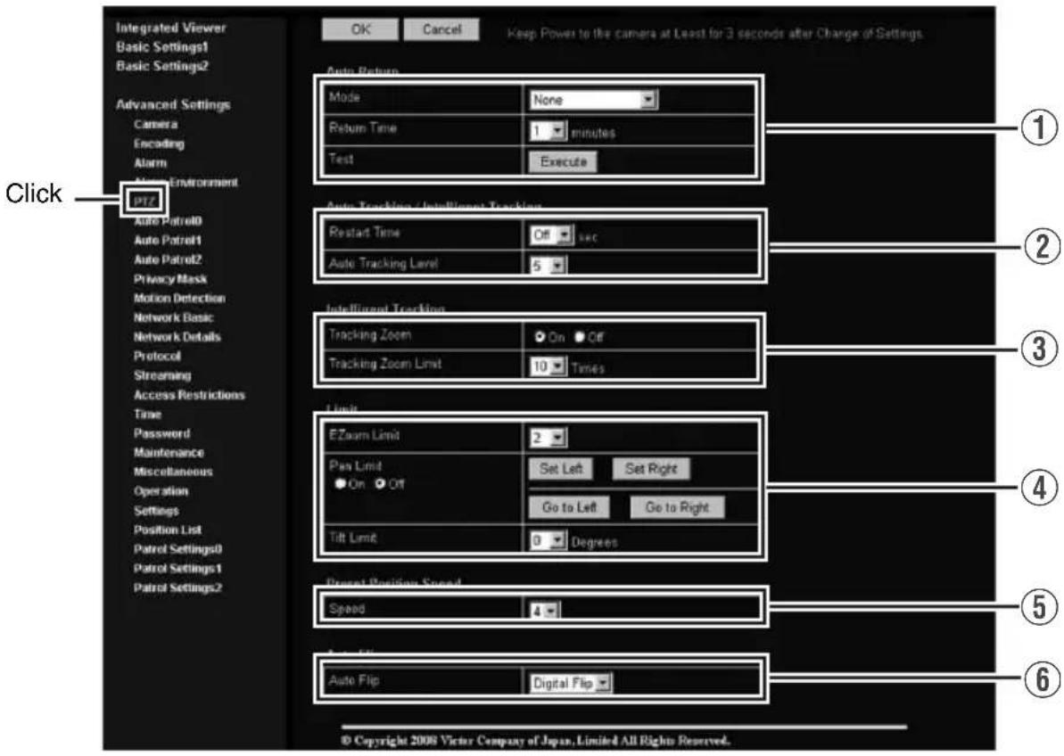
| 1 Auto Return | If the camera is not operated over the duration that was set in “Return Time”, it will automatically return to the state that was set in “Mode”. |
| Mode This item sets the operation after Auto Return. none: Auto Return is disabled. Home: Returns to the home position. Auto Pan: Returns to the Auto Pan operation. Auto Patrol: Returns to the Auto Patrol operation. Auto Trace: Returns to the Auto Trace operation. Auto Tracking: Returns to the automatic tracking operation. Intelligent Tracking: Returns to the Intelligent Tracking operation. | |
| 1Auto Return (continued) | |
| Return Time This | tem sets the time to return the operation with Auto Return.This feature cannot be configured when the [Mode] is set to “none”.[Setting value:1 minute, 2minutes, 3minutes, 5minutes, 10minutes, 20minutes, 30minutes, 60minutes]Memo:When the [Mode] item is set to “Intelligent Tracking”, the camera returns to the home position after the specified Return Time has elapsed, and action restarts from the detection of tracked objects. When the Intelligent Tracking operation is in progress, PTZ may not function even when an object is being captured. If PTZ operations do not function for a time interval specified in “Return Time”, Auto Return starts automatically. |
| Test | Click [Execute] to test run the configured Auto Return operation. |
| 2Auto Tracking/ Intelligent Tracking | For configuring settings related to Auto Tracking and Intelligent Tracking.Auto Tracking : Moves to the home position when Auto Return starts.Shoots the object by tracking it automatically when motion is detected at the home position. Zoom ratio is fixed at x1.Intelligent Tracking: Intelligent Tracking is available in two modes, namely the Auto mode which starts automatically from Auto Return, and the Manual mode for specifying a target on the viewer. You can change the object to track freely by clicking the viewer’s display area when the camera is in the “Locked” or “Losing” mode. To exit, press the [Stop] button on the PTZ Controller screen.Auto modeDetects the color information of the object for which motion is detected at the home position, and shoots the object by tracking it with automatic pan/tilt/zoom operations. You can switch to the Manual mode by clicking on the viewer screen before any motion is detected.Manual mode (Page 113)Select “Intelligent Tracking” under the [Function] item on the PTZ Control screen, and press the [Start] button to switch to the “Standby” mode. Once you click on the viewer screen to specify a target, the camera automatically tracks and shoots the target object while performing automatic pan/tilt/zoom operations.Memo:Auto tracking may be difficult under the following conditions.When multiple moving objects are in the same screenWhen there is a flickering light source in the screenWhen the speed of the moving object is too fast or slowWhen the moving object is too big or smallWhen the object and background have same brighthnessIntelligent tracking may be difficult under the following conditions.Strong backlightColors that are similar to the tracking target are present in the same screenNo colors on the tracking target (such as white, gray, black)When the tracking target moves into the privacy mask area |
Setting (continued)
PTZ Page (continued)
| 2Auto Tracking/IntelligentTracking(continued) | Memo:● Intelligent tracking cannot begin under the following conditions.● [B/W Mode] is set to “Black & White” (Page 55)● [B/W Mode] is set to “Auto” and black and white is selected (Page 55)● [Auto Flip] is set to “Digital Flip” (Page 71)● All areas of detected motion are masked (Page 76)● The zoom ratio exceeds 20x. (The zoom ratio of the home position exceeds 20x if Intelligent Tracking is started by Auto Return.)● Dark images can be improved with the [Sense Up] (Page 54) function but the tracking may be slow.Note:● The Auto Tracking function of this camera detects changes in brightness. As such, depending on changes in the illumination, it may or may not detect movement of objects having the same color as the background color. It may be difficult to detect objects with very slow movement. Check the operating conditions thoroughly beforehand and configure the settings such that there will not be any misoperation or omission of detection.● When [Stabilizer] (Page 53) is set to “OFF”, this function starts from home position and initial detect area is the screen of the home position without enlargement. When [Stabilizer] is set to “ON”, as the screen is enlarged, it will also respond to motion of image which is not shown on the screen. This is the specification of this unit, not a malfunction. |
| Restart Time | Auto Tracking : This item sets the duration to return to the home position when there is no movement in the images after auto tracking starts.Intelligent Tracking: When Intelligent Tracking loses the object, you can return to the home position after the preset [Restart Time] has elapsed.For Intelligent Tracking, the camera does not return to home position while the object is locked even if the object does not move.[Setting value:Off, 10seconds, 20seconds, 30seconds, 40seconds, 50seconds, 60seconds, 120seconds]Note:● When the [Mode] item of [Auto Return]1 is set to “Auto Tracking” and the [Return Time] is set shorter than the [Restart Time] for [Auto Tracking]2, the camera will operate according to the [Return Time]. |
| Auto Tracking Level | This item sets the detection sensitivity of Auto Tracking/Intelligent Tracking.To lower the sensitivity → Decrease the numberTo increase the sensitivity → Increase the number[Setting range:0 to 10] |
| 3Intelligent Tracking | This item sets the zoom for [Intelligent Tracking]. |
| Tracking Zoom | When this item is set to “On”, the zoom ratio changes according to the movement of the object. |
| Tracking Zoom Limit | When [Tracking Zoom] is set to “On”, this item sets the threshold limit of the zoom ratio.When Intelligent Tracking is started, tracking is possible if the zoom ratio is within 20x, even if the current zoom ratio has exceeded the [Tracking Zoom Limit]. In that case, behaviour of automatic zoom changes according to the [Tracking Zoom] setting as followings.[Tracking Zoom] is “On”:Tracking starts at the current zoom ratio. If the [Tracking Zoom Limit] is exceeded, the camera moves in the WIDE direction but not in the TELE direction. Once the zoom ratio enters the [Tracking Zoom Limit], the camera will zoom within the configured tracking zoom limit.[Tracking Zoom] is “Off”:The camera tracks objects at the current zoom ratio. The zoom ratio will not change. |
| 4Limit | |
| Zoom Limit When | the zoom lens is operated to TELE side, optical zoom works and electronic zoom works after optical zoom becomes full. This item sets the maximum value of the electronic zoom function.[Setting range:Off, 1, 2, 4, 8, 16, 32]Memo:As electronic zoom processes the images digitally, image quality will deteriorate somewhat.Increasing the electronic zoom ratio will shift the center of the screen toward the top left. This is a characteristic of this camera and is not a malfunction.The camera will not operate continuously from optical zoom to electronic zoom. When the optical zoom is full, release and press again the [+] button of [Zoom] in [PTZ Controller].[PTZ Control] (Page 113) |
| Pan Limit This item | sets the movable range of the pan (horizontal) operation during manual operation when “On” is selected. It is invalid when “Off” is selected.[Set Left], [Set Right] button: Click these buttons to set the current position to the left or right edge.[Go to Left], [Go to Right] button: Click these buttons to move the camera to the preset left or right edge.Memo:It does not affect the Preset Position, Auto Pan and Auto Trace operations. |
Setting (continued)
PTZ Page (continued)
| 4Limit (continued) | |
| Pan Limit(continued) | ■Basic operation of Pan LimitWhen [Pan Limit] is set to “On”, panning is only available in the effective area. When the camera is moved to prohibited area by some operation that has priority over [Pan Limit] and manual panning is performed, it operates in the following manner.Panning can be operated freely even in the prohibited area before the camera enters the effective area.Once the camera enters the effective area, the [Pan Limit] settings take over and pan operation can only be performed in the effective area.●Operations that have priority over Pan LimitThe following operations are available regardless of the prohibited areas set in [Pan Limit].●Auto Pan●Auto Trace●Move Preset Position●Auto Flip●Auto Tracking●Settings that have priority over Pan LimitThe following settings come together with pan operation but they can be set regardless of the prohibited areas even when [Pan Limit] is set to “On”.●Privacy Mask Setting●Auto Pan settingMemo:·When setting Auto Trace and Preset Position and the [Pan Limit] setting is “On”, panning is unavailable in the prohibited area.As Auto Trace and Move Preset Position have priority over manual pan limit, setting pan limit after setting Auto Trace or Preset Position does not prevent Auto Trace or Preset Position operation. |
| Tilt Limit | This item sets the movable range of the tilt (vertical) operation during manual operation.When this item is set to 10, the movable range of the tilt operation is from 10 to 90 degrees. It cannot operate between -5 and 9 degrees.[Setting range:-5 Degrees to 0 Degrees to 10 Degrees]Memo:·When the camera is moved to prohibited area by some operation that has priority over tilt limit and tilt operation is performed manually, it operates in the following manner.Tilt operation is disabled in the prohibited area. Tilt will be forcibly moved to the effective area.Once the camera enters the effective area, the tilt limit settings take over and tilt operation can only be performed in the effective area.It does not affect the Preset Position, Auto Pan and Auto Trace operations. |
| 5Preset Position Speed | This item sets the speed of moving to the preset position. It is also applicable when moving to the preset position in Auto Patrol. |
| Speed [Setting value:1 to 4] | |
| 6 Auto Flip | Set this item when shooting objects that pass right under the camera. Otherwise, following operations are necessary to shoot objects that pass right under the camera.1Turn the camera to face down2Rotate the camera 180° horizontally3Turn the camera to face upYou can use the [Auto Flip] function to perform the above operations automatically.Off: Auto Flip function does not activate.Digital Flip: The top/bottom and left/right of the image flips when tilt position passed the angle of 135 degrees.Mode1: When the camera faces bottom, it rotates 180° horizontally and stops. In this case, the operating direction of the camera is the same as that of the Pan/Tilt operation.Mode2: When the camera faces bottom, it rotates 180° horizontally and the operating direction of the camera is opposite that of the Tilt operation. Select this mode if you wish to operate continuously. Once operation stops, the direction will return to normal.Mode3: When the camera faces bottom, it rotates 180° horizontally and the operating direction of the camera is opposite that of the Tilt operation. However, the operating direction will return to normal 10 seconds after the operation has stopped.[Setting value:Off, Digital Flip, Mode1, Mode2, Mode3]Memo:[Intelligent Tracking] is disabled when this is set to “Digital Flip”. (Page 67)Settings for [Preset Position Speed] are reflected in the rotation speed when images are flipped using “Mode1”, “Mode2”, “Mode3”. To flip images in high speed using “Mode1”, “Mode2”, “Mode3”, set the [Speed] in [Preset Position Speed] to “4”.Note:When [Auto Flip] is set to other than “Off”, the camera can be moved to areas outside the pan limit with the Tilt operation. When “Digital Flip” is set, use the Tilt operation to flip and return to the pan limit area again. When “Mode1”, “Mode2” or “Mode3” is set and the camera is moved to inside of the pan limit with Pan operation, it will stop at the pan limit position. |
Setting (continued)
Auto Patrol Page
This function sets the Auto Patrol operation which patrols multiple positions at specified time intervals. You can set the order in which to view the determined positions. This page can be used during access using “admin” or “operator”.
- Click [Advanced Settings] to display setting menu.
- Click [Auto Patrol]. Press the [OK] button to enable the new settings. Press the [OK] button to enable the new settings.
- If the [OK] button is pressed upon entering an invalid value, a warning message will appear and the entry will be denied. Press the [Cancel] button to restore the invalid entry to the current value.
![graph TD A["Store Entry"] --> B["Store Purchase"] B --> C["Sales Store"] C --> D["Online Shopping"] D --> A](/content/2026/06/1352302/images/31c76fd2dfa3eb780b56e953a0c3f2a6decb19b91c93b81fd3d3e0b10f927b7c.jpg)
There are three screens in Auto Patrol.

| 1 No | Switches the camera image from No. 0 to 99 in sequence. |
| 2 Title This displays the title of the position. | |
| 3 Position | This sets the position number to be moved in sequence.[Setting value:0 to 99] |
| 4 Time | This sets the duration of staying at the position. (Unit: Seconds)[Setting range:Skip, 10 sec, 20 sec, 30 sec, 45 sec, 60 sec, 120 sec] |
Setting (continued)
Privacy Mask Page
Privacy Mask is a feature that enables masking of a portion of the image. You can set 8 rectangular privacy masks for this unit.
This page can be used during access using "admin" or "operator".
- Click [Advanced Settings] to display setting menu.
- Click [Privacy Mask]. Press the [OK] button to enable the new settings.
- Press the [OK] button to enable the new settings.

| 1 Privacy Mask | For specifying whether to activate the Privacy Mask feature.When this is set to “On”, the privacy mask specified using the following items will appear on the screen.Memo:●When setting privacy mask, zoom will be at the Wide edge and [Digital Flip] is set to “Off”. |
| 2 Mask Settings | This item adjusts the mask. Click this item to open the [Adjustment] screen.To change the setting, first, enter [Operator Password] in the [Password] screen. (Page 44)If the [Operator Password] was entered already to setting page of built-in viewer, it will be displayed as●●●●●●.■[Mask Settings] screen1[Adjustment], [Brightness], [Password] tabEach setting screen appears.-2[Mask] When “Off” is selected, mask will not be displayed on the screen.[Setting value:0 to 7]-3[Size]This item sets the size of the mask.Use the [Shrink] or [Expand] button to set the “Hight” or “Width” of the mask.[Position]5[Save] This saves the new settings. This sets the position to place the mask.Set the moving speed in [Pan/Tilt Speed].[Delate][Setting values:1 to 8]This removes the privacy mask of the specified mask number.■[Brightness] screenThis item sets the brightness (color) of the mask.“0” is black. The larger the number is, the closer the color is to white. When the number is “10”, the color is white. You can check the color at [Image].[Setting value:0 to 10]■[Password] screenEnter the “Operator Password”. (Page 44) When “Off” is selected, mask will not be displayed on the screen.[Setting value:0 to 7]-3[Size]This item sets the size of the mask.Use the [Shrink] or [Expand] button to set the “Hight” or “Width” of the mask.[Position]5[Save] This saves the new settings. This sets the position to place the mask.Set the moving speed in [Pan/Tilt Speed].[Delate][Setting values:1 to 8]This removes the privacy mask of the specified mask number.■[Brightness] screenThis item sets the brightness (color) of the mask.“0” is black. The larger the number is, the closer the color is to white. When the number is “10”, the color is white. You can check the color at [Image].[Setting value:0 to 10]■[Password] screenEnter the “Operator Password”. (Page 44) |
Note:
- The tilt angle where mask can be set is within 40 degrees from the horizontal position.
- To change the privacy mask position to upper area from horizontal direction, press the up button until the end of the horizontal position, release the button, and press it again. Only the privacy mask will be moved to upper area. This will set the privacy mask at the area above the shallow horizontal position.
- The mask will appear larger than when it is set. If some area that you wish to hide appear due to the camera direction or zoom, set the mask larger.
- The default home position is outside the range of the privacy mask.
- When the [Adjustment] window is opened in the computer for the first time, ActiveX will be installed.
Setting (continued)
Motion Detection Page
This page is for setting motion detection.
This page can be used during access using "admin" or "operator".
- Click [Advanced Settings] to display setting menu.
- Click [Motion detection]. Press the [OK] button to enable the new settings.
●The area valid for motion detection is displayed in blue.
- When motion is detected, the image screen edge is displayed in red.
- Information of the configured mask is also applicable for detecting the tracking target of Intelligent Tracking, which starts from Auto Return. (Page 67)

| 1 Display Screen | The screen is divided into blocks of 12 (horizontal) x 8 (vertical). Use this to set whether to mask each block.All blocks are masked in the default setting.The block turns blue when it is clicked, indicating that it is unmasked. Click again to return to the masked state.Press the [OK] button to enable this setting.Use the [Mask All] button to mask all blocks.Use the [Clear Mask] button to unmask all blocks. |
| 2Detection For setting | the On/Off of [Detection].Press the [OK] button to enable this setting.Motion detection does not work during [Auto Tracking/Intelligent Tracking](Page 67). |
| 3 OK/Cancel | To apply the new parameters, press the [OK] button.Press the [Cancel] button to cancel the change. |
| 4 Level | For setting the sensitivity of motion detection.Increasing the number raises the detection sensitivity level, and hence it is more sensitive.Press the [OK] button to enable this setting.[Setting value:0 to 10] |
| 5Mask All Masks all blocks. | Press the [OK] button to enable this setting. |
| 6Clear Mask Unmasks | all blocks.Press the [OK] button to enable this setting. |
Memo:
- The area display position serves as a reference. Make sure to perform operation check.
- The screen is divided into blocks of 96 (12 horizontal x 8 vertical). Set the angle of view such that the size of the object for which motion is to be detected is larger than the size of multiple blocks.
- When [Stabilizer] is set to "On", the image is zoomed to 1.3 times. Thus, the number of blocks displayed on the motion detection setting screen becomes 48 (8 horizontal x 6 vertical). (Page 53)
Note:
- Flickers of fluorescent lamps may cause motion detection.
●Changes in brightness due to the light source may be detected as motion. - The motion detection feature is not intended to prevent theft or fire. This feature may not function properly depending on the conditions of the object and settings. Our company shall not be liable for any accident or damage that occurs.
- When other client is getting JPEG/MPEG4 stream from this unit, video images may not appear on the [Motion Detection] page due to the maximum distribution limit of the camera. Stop other clients before using the [Motion Detection] page.
Setting (continued)
Network Basic Page
This page is for performing basic setting related to the network.
This page can be used during access using "admin".
- Click [Advanced Settings] to display setting menu.
- Click [Network Basic]. Press the [OK] button to enable the new settings.
- Press the [OK] button to enable the new settings.
- If the [OK] button is pressed upon entering an invalid value, a warning message will appear and the entry will be denied. Press the [Cancel] button to restore the invalid entry to the current value.
- When settings of the Basic page is changed, all services that are currently running will end immediately. For example, when changes are made to the [Network Basic] page during JPEG/MPEG4 distribution, distribution will be discontinued and TCP will be disconnected.
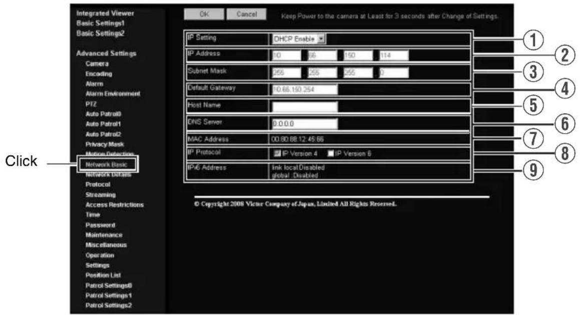
| 1IP Setting For setting | the DHCP client function. Connect the camera to a network environment with a DHCP server when DHCP is to be enabled. If the DHCP server does not exist when [IP Setting] is set to “DHCP Enable”, the camera will start running with IP address 192.168.0.2 and subnet mask 255.255.255.0 in about 2 minutes after startup. Refer to [IP Address Settings] (e) Page 36) for the IP address. |
| 2IP Address For setting | the IP address of the camera. |
| 3 Subnet Mask | For setting the subnet mask of the camera. |
| 4 Default Gateway | For setting the default gateway of the camera. Set as “0.0.0.0” when a default gateway is not set. |
| 5 Host Name | For setting the host name of the camera. Specify a name using alphanumeric characters, hyphen (-) or period (.). Underscores (_) cannot be used. |
| 6 DNS Server | For setting the address of the DNS server. |
| 7 MAC Address | The MAC address of the camera is displayed in a hexadecimal number. |
| 8 IP Protocol | For setting IPv6 to “On” or “Off”. (IPv4 is set to “On” at all times.) When IPv6 is set to “On” in a network that supports IPv6, the address appears in the [IPv6 Address] field. If the network does not support IPv6, “Disable” appears in the [IPv6 Address] field. Camera will restart if this item is altered. Wait for about one minute before operation of the unit is enabled. |
| 9IPv6 Address Displays the IPv6 address. | |
Setting (continued)
Network Details Page
This page is for performing detailed network setting.
This page can be used during access using "admin".
- Click [Advanced Settings] to display setting menu.
- Click [Network Details]. Press the [OK] button to enable the new settings.
- Press the [OK] button to enable the new settings.
- If the [OK] button is pressed upon entering an invalid value, a warning message will appear and the entry will be denied. Press the [Cancel] button to restore the invalid entry to the current value.
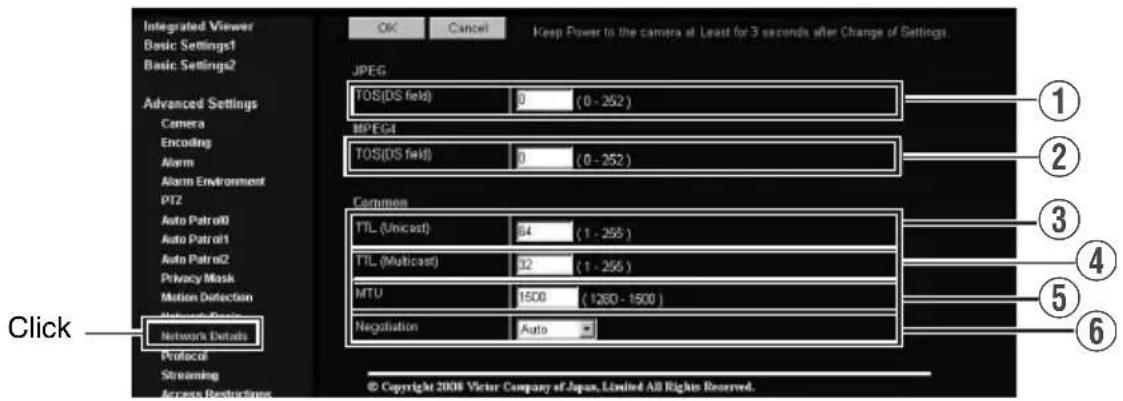
| JPEG | ||
| 1 TOS(DS field) | For setting the TOS value of IP packets in which JPEG is stored.The upper six bits out of the eight bits that make up the TOS value belong to DSCP.This upper six bits can be set. The lower two bits are “0”. For example, upon setting to “255”, the lower two bits are converted to “0”, and the value becomes “252”.TOS values are used in networks that support QoS. By setting QoS for the network switch, routing can be done by giving priority to packets with a larger TOS value. | |
| MPEG4 | ||
| 2 TOS(DS field) | For setting the TOS value of IP packets in which MPEG4 is stored.For details, refer to the [JPEG TOS(DS field)] item 1 above. | |
| Common | ||
| 3 TTL (Unicast) | For setting the TTL value of JPEG/MPEG4 packets that are to be sent via TCP. | |
| 4 TTL (Multicast) | For setting the TTL value of JPEG/MPEG4 packets that are to be sent via multicast. | |
| 5 MTU | For setting the maximum packet size for storing JPEG/MPEG4.[Setting range:1280 to 1500] | |
| 6 Negotiation | For setting the [Negotiation] of the [Network Details].When a value other than “Auto” is selected, do not set the network device to be connected to “Auto”. Ensure that it is set to the same value as the camera. | |
Protocol Page
This page is for changing the HTTP server port number.
This page can be used during access using "admin".
- Click [Advanced Settings] to display setting menu.
- Click [Protocol]. Press the [OK] button to enable the new settings.
- Press the [OK] button to enable the new settings.
- After changing, you will need to re-establish the connection if you are using the Internet Explorer.

| 1HTTP Server Port | You can change the port number for the built-in web server of the camera. (1-65535)The default port number setting is “80”. The port number of JPEG/MPEG4 server is changed also.To access to camera from the Internet Explorer, enter the following in the Internet Explorer when the camera is in its default settings.http://192.168.0.2If the port number is changed to “8080”, for example, enter the Internet Explorer as follows.http://192.168.0.2:8080 |
| 2 VISIP Protocol | You can change the On/Off setting of VSIP Protocol. To use this unit from Nextiva of Verint Systems Inc., select “On”. |
| 3HTTP Server Port | You can change the port number for Built-in VSIP server of the camera. (1-65535) The default port number setting is “5510”. |
| 4AMX Device Discovery Protocol | You can change the On/Off setting of AMX device detection protocol. Set to “On” when you are using the camera on AMX’s systems.[Setting value:On , Off] |
Memo:
- If Built-in Viewer is used for playback, change the [HTTP Port] number in the setting screen of Built-in Viewer to the same value. (Page 119)(Page 121)
Setting (continued)
Streaming Page
This page is for setting manual multicast transmission.
This page can be used during access using "admin" or "operator".
- Click [Advanced Settings] to display setting menu.
- Click [Streaming]. Press the [OK] button to enable the new settings.
- Press the [OK] button to enable the new settings.
- If the [OK] button is pressed upon entering an invalid value, a warning message will appear and the entry will be denied. Press the [Cancel] button to restore the invalid entry to the current value.

| JPEG | |
| 1 Control | For starting or stopping streaming of JPEG images.Parameters that are set on the [Streaming] page will be saved when transmission is started upon pressing the [Start] button. |
| 2 Destination Address | For specifying the destination address of JPEG streaming.Specify the multicast address. When other devices that make use of multicast transmission exist, ensure that each of them is set to a different multicast address. |
| 3 Destination Port | For specifying the destination port number of JPEG streaming.Specify an even number for RTP compliance.When other devices that make use of multicast transmission exist, it is recommended that each of them be set to a different port number.Multiple multicast streams cannot be received on a single computer when there are duplicate port numbers. |
| 4 Frame Rate | For specifying the frame rate when sending JPEG images via multicast. |
| MPEG4 | |
| 5 Control | For starting or stopping streaming of MPEG4 images.Parameters that are set on the [Streaming] page will be saved when transmission is started upon pressing the [Start] button. |
| 6 Destination Address | For specifying the destination address for MPEG4 streaming.Specify the multicast address. When other devices that make use of multicast transmission exist, ensure that each of them is set to a different multicast address. |
| 7 Destination Port | For specifying the destination port number for MPEG4 streaming.Specify an even number for RTP compliance.When other devices that make use of multicast transmission exist, it is recommended that each of them be set to a different port number.Multiple multicast streams cannot be received on a single computer when there are duplicate port numbers. |
Memo:
- When the power of the camera is turned off accidentally during multicast transmission, multicast transmission will restart automatically after the camera is rebooted.
Setting (continued)
Access Restrictions Page
This page is for setting client restrictions.
This page can be used during access using "admin".
- Click [Advanced Settings] to display setting menu.
- Click [Access Restrictions]. Press the [OK] button to enable the new settings.
- Press the [OK] button to enable the new settings.
- If the [OK] button is pressed upon entering an invalid value, a warning message will appear and the entry will be denied. Press the [Cancel] button to restore the invalid entry to the current value.
- This feature is targeted at JPEG/MPEG4 acquisition. It does not impose restrictions on access via a web browser or use of API.
Note:
- The Access Restriction feature determines whether to impose restrictions during TCP connection by the client. In the case when access restriction is set after TCP connection by a client has been established, TCP connection will not be disconnected.

| Destination Address | Restrictions may be imposed on clients accessing the camera using the IP address. |
| 1Access Restrictions | When “deny” is selected, acquisition of JPEG/MPEG4 via the IP address specified for the [IP Address] item 2 will be denied. Restrictions are not imposed on access to the Web Settings page.When “allow” is selected, acquisition of JPEG/MPEG4 via the IP address specified for the [IP Address] item 2 will be permitted. Restrictions are not imposed on access to the Web Settings page. |
| 2IP Address | When a multicast address is specified and “deny” is selected, the camera will deny transmission to this multicast address.When a multicast address is specified and “allow” is selected, the camera will only accept transmission to this multicast address and deny transmission to multicast addresses that are not stated in the [IP Address] item 2 field. |
Note:
- Note that when “allow” is selected and all IP address fields are left blank, JPEG/MPEG4 acquisition by all IP addresses will be denied. Restrictions are not imposed on access to the Web Settings page.
Additionally, the camera will also deny access when instructions for transmission to the specified IP address are sent via API.
Memo:
- To specify a specific IP address range, enter a combination of the IP address and subnet mask in the [IP Address] item ② field.
- Define the subnet mask using a length between 8 to 30 bits.
For example, a range between 192.168.0.0 to 192.168.0.255 is denoted as 192.168.0.0/24 ([IP Address]/[bit length of subnet mask]).
Setting (continued)
Time Page
This page is for setting time.
This page can be used during access using "admin".
- Click [Advanced Settings] to display setting menu.
- Click [Time]. Press the [OK] button to enable the new settings.
- Press the [OK] button to enable the new settings.
- If the [OK] button is pressed upon entering an invalid value, a warning message will appear and the entry will be denied. Press the [Cancel] button to restore the invalid entry to the current value.

| 1SNTP For setting the SNTP client feature.When this is set to “On”, the system accesses the specified NTP server at regular intervals to acquire the time.In addition, time will be recorded in the JPEG headers distributed by the camera. Discontinuity in JPEG header’s time may occur immediately before and after acquiring time from the NTP server. | |
| 2NTP Server | For setting the IP address of the NTP server. |
| 3Access Interval | For setting the time interval for access to the NTP server. |
| 4Time Displays the time on the clock of the camera.The clock time can be changed by entering an appropriate value. (Second value cannot be specified.)In addition, time will be recorded in the JPEG headers distributed by the camera. Discontinuity may occur in the JPEG header’s time immediately before and after changing the time. | |
| 5Time Zone For setting the time zone. | |
| 6PC Time to Camera | Click [Set] to load the clock time of the computer in use on the camera. |
Password Page
This page is for setting the password.
This page can be used during access using "admin".
- Click [Advanced Settings] to display setting menu.
- Click [Password]. Press the [OK] button to enable the new settings.
- Press the [OK] button to enable the new settings.

| 1Username Select a | user name. |
| 2New Password Enter | a new password.Passwords should be 8 characters or less (no space allowed). Camera is case-sensitive. |
| 3New Password Again | Enter again to confirm the new password. |
Note:
- Be sure to handle the password carefully in case you forget it.
- If you have forgotten the password, please consult your nearest JVC dealer.
Setting (continued)
Maintenance Page
This page is for maintenance purposes.
This page can be used during access using "admin".
- Click [Advanced Settings] to display setting menu.
- Click [Maintenance]. Press the [OK] button to enable the new settings.

| 1 Restart | Reboots the camera. (It takes about one minute for the camera to reboot.) |
| 2All Settings [Initialize] | Restores all settings to their default values and reboots the unit. (It takes about one minute for the camera to initialize and reboot.)Passwords will also be initialized. The built-in clock of the camera will not be affected. JPEG/MPEG4 transmission and all other services that are running will be discontinued. |
| 3 Update | Upgrades the firmware version of the camera and reboots the unit.Select the update target from [Streaming Manager], [PTZ Controller] or [Image Processor].The settings of the camera will be saved. Copy the new firmware file to the computer on which Internet Explorer is used, and specify this file using the [Browse...] button. Press the [Update] button to start the update. JPEG/ MPEG4 transmission and all other services that are running will be discontinued. The update process may take several minutes.A message will be displayed on the Internet Explorer when update is successfully completed.Note:Do not turn off the power when update is in progress or during reboot after update is complete. Turning off the power of the camera may cause it to malfunction.Before updating, end all accesses to the camera (such as viewer) other than from this page. If there are accesses from other pages, when update starts, the access from this page may be disconnected. In this case, end all the accesses from other pages, then access this page and try updating again. |
| 4 Auto Cleaning | This item sets whether to automatically clean the power and signal transmission components.Note:When the camera has stopped at the pan position for more than 7 days, it will pan at the specified time and perform cleaning automatically. |
| 5 Auto Cleanig Time | This item sets the time to start cleaning.To change the setting, enter the time and click the [Apply] button.[Setting values:0-23 h, 0-59 m] |
Setting (continued)
List of Factory Settings of Each Page
| Item Factory Settings | |
| Action | Disable |
| 1st Trigger | Input 1 Make |
| Max. Interval | — |
| 2nd Trigger Disable | |
| Action Position No. | — |
| Trigger Position No. | — |
| Mail Address | — |
| Mail Text | |
| Attach Image | Off |
| TCP/UDP IP Address | — |
| TCP/UDP Port Number | — |
| TCP/UDP Data | — |
| Alarm Output Duration | — |
| Time Filter | Unmask All |
■ Alarm Environment Page( page 62)
| Item Factory Settings | |
| SMTP Server 0.0.0.0 | |
| Port Number 25 | |
| Send Mail Address — | |
| POP before SMTP Off | |
| POP Server 0.0.0.0 | |
| Port Number 110 | |
| Username — | |
| Password — | |
| FTP Server 0.0.0.0 | |
| Directory — | |
| Username — | |
| Password — | |
| Periodic FTP | Off |
| Periodic FTP Interval | 1 |
| Periodic FTP Time Filter | Auto |
| Periodic FTP Time Filter | Unmask All |
| PrePostRecording Frame Rate | 15 fps |
| PrePostRecording Before Trigger | 5 sec |
| PrePostRecording After Trigger | 5 sec |
| Duration Output1 | 1000 msec |
| Duration Output2 | 1000 msec |
| Manual Output Output1 | Break |
| Manual Output Output2 | Break |
■ PTZ Page(Page 66)
| Item Factory Settings | |
| Mode | none |
| Return Time 1 minute | |
| Restart Time | Off |
| Auto Tracking Level | 5 |
| Tracking Zoom | On |
| Tracking Zoom Limit | 5 Times |
| EZoom Limit 2 | |
| Pan Limit | Off |
| Tilt Limit | 0 degree |
| Preset Position Speed | 4 |
| Auto Flip Digital Flip | |
Setting (continued)
List of Factory Settings of Each Page (continued)
■ Auto Patrol Page( Page 72)
| Item Factory Settings | |
| Position (Preset Position | number) |
| Time 10 | |
■ Privacy Mask Page(→ Page 74)
| Item Factory Settings | |
| Privacy Mask Off | |
| Mask 0 to 7 Off | |
| Brightness 4 | |
| Password — | |
■ Motion Detection Page(→ Page 76)
| Item Factory Settings | |
| Mask Clear Mask | |
| Detection Off | |
| Level 5 | |
■ Network Basic Page(Page 78)
| Item Factory Settings | |
| IP Setting DHCP Enable | |
| IP Address 192.168.0.2 | |
| Subnet Mask 255.255.255.0 | |
| Default Gateway 192.168.0.254 | |
| Host Name | — |
| DNS Server | 0.0.0.0 |
| IP Protocol IP version4 | IP version6 |
| IPv6 Address | Disable |
■Network Details Page(→ Page 80)
| Item Factory Settings | |
| JPEG TOS 0 | |
| MPEG4 TOS | 0 |
| TTL (Unicast) | 64 |
| TTL (Multicast) | 32 |
| MTU | 1500 |
| Negotiation | Auto |
■Access Restrictions Page
(Page 84)
| Item Factory Settings | |
| Access Restrictions deny | |
| IP Address — | |
This page is for acquiring information.
This page can be used during access using "admin", "operator" and "user".
- Click [Advanced Settings] to display setting menu.
- Click [Miscellaneous]. Press the [OK] button to enable the new settings.

| 1Open Source Software | Press the [Show] button to display information of the software used by the camera. |
Operation Page
Displays the operating status of the camera.
This page can be used during access using "admin" or "operator".
- Click [Advanced Settings] to display setting menu.
- Click [Operation]. Press the [OK] button to enable the new settings.

| Operation | ||
| 1Total Sending Bitrate | Displays the total TCP/UDP bit rate sent by the camera as well as the individual bit rates. | |
| 2 Destination | Displays the destination that the camera is sending data to. | |
| Log | ||
| 3System Log Displays | the following information.●Number of seconds after startup●Alarm information | |
Setting (continued)
Settings Page
This page displays the version information and settings of the camera.
This page can be used during access using "admin" or "operator".
- Click [Advanced Settings] to display setting menu.
- Click [Settings]. Press the [OK] button to enable the new settings.

| JPEG | |
| Quality | VFS1 |
| Size | 80 KB |
| MPEG4 | |
| Etrate | 2000 kbps |
| Etrate Control | CBR |
| FPS | 16 fps |
| 1 Frame Interval | 30 frames |
| Priority | FPS |
Alarm Setting
| No. | Trigger / Action | |
| 01 | Trigger | —— |
| Action | Off | |
| 02 | Trigger | —— |
| Action | Off | |
| 03 | Trigger | —— |
| Action | Off | |
| 04 | Trigger | —— |
| Action | Off | |
| 05 | Trigger | —— |
| Action | Off | |
Alarm Environment
| SMTP ( SMTP Server 0.0.0.0 )SMTP ( Port Number: 25 )Send Mail Address :SMTP ( POP before SMTP: Off )POP ( POP Server: 0.0.0.0 )POP ( Port Number: 110 )POP ( Username ) | |
| FTP | FTP Server 0.0.0.0DirectoryUsername:Periodic FTP: OffPeriodic FTP Internal: 1Periodic FTP Naming: AutoPrePostRecording Frame Rate: 15 fpsPrePostRecording Before Trigger: 5 secPrePostRecording After Trigger: 5 sec |
| Alarm Output | Output1 Duration: 1000 msecOutput2 Duration: 1000 msec |
PTZ
| Auto Return | |
| Mode | Name |
| Return Time | 1 minute |
Auto Tracking / Intelligent Tracking
| Restart Time | Off |
| Auto Tracking Level | 5 |
Intelligent Tracking
| Tracking Zoom | On |
| Tracking Zoom Limit | 10 Times |
limit
| EZoom Limit | 2 |
| Pan Limit | Off |
| Trit Limit | 0 Degrees |
Preset Position Speed
| Speed | d |
Auto Flip
| Auto Flip | Digital Flip |
Setting (continued)
Settings Page (continued)
| Motion Detection | ||
| Detection | Off | |
| Level | 5 | |
| Mask Area | FITFIFIFIFIFIFIFIFIFIFIF | |
| Network Basic | ||
| IP Address | 10 66 150 113 | |
| Subnet Mask | 256.255 255.0 | |
| Default Gateway | 10 66 150 254 | |
| Host Name | ||
| DNS Server | 0 0 0 0 | |
| MAC Address | 00.80/88 43 11:34 | |
| IP Protocol | IP Version 4 IP Version 6 | |
| IP& Address | link local disabled global Disabled | |
| Network Details | ||
| JPEG | ||
| TOS/DS field) | 0 | |
| MPEGI | ||
| TOS/DS field) | 0 | |
| Common | ||
| TTL (Unicast) | 84 | |
| TTL (Multicast) | 32 | |
| MTU | 1600 | |
| Negotution | Auto | |
| Protocol | ||
| HTTP Server Port | 80 | |
| VSIP Protocol | On | |
| VSIP Server Port | 6510 | |
| AMX Device Discovery Protocol | On | |
| Streaming | ||
| JPEG | ||
| Status | —— | |
| Address | 225 0 1 1 | |
| Port | 49162 | |
| Frame Rate | 15 | |
| MPEGI | ||
| Status | —— | |
| Address | 225 0 2 1 | |
| Port | 69162 | |
| Access Restriction | ||
| Access Restriction | deny | |
| IP Address | ||
| Time | ||
| DNTP | SMTP, Off NTP Server 192 108 0.1 Access Interval 1 time | |
| Time / Time Zone | Time: 2008/09/22-16, 11, 20 (V/MID-h.m.s.) Time Zone (GMT+9.00) Japan | |
Position List Page
This page displays information on preset positions.
This page can be used during access using "admin" or "operator".
- Click [Advanced Settings] to display setting menu.
- Click [Position List]. Press the [OK] button to enable the new settings.
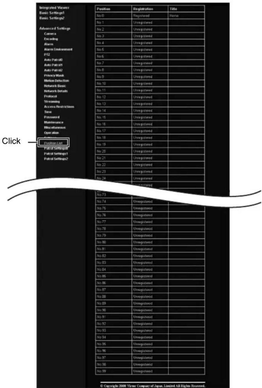
Setting (continued)
Patrol Settings Page
This page displays the information and settings of Auto Patrol.
This page can be used during access using "admin" or "operator".
- Click [Advanced Settings] to display setting menu.
- Click [Patrol Infomation]. Press the [OK] button to enable the new settings.

Built-in Viewer
This product comes with a built-in integrated viewer.
The built-in viewer is activated by entering an IP address into the Internet Explorer. The built-in viewer enables monitoring and PTZ operation to be done in either JPEG or MPEG4 formats.
■ Using the compressed JPEG format enables display of a series of still images as well as one-shot recording of still images.
■Using the compressed MPEG4 format enables display of MPEG4-encoded motion images.
◆ “Operation” (Page102)
◆ “Image quality setting” (Page104)
◆ “PTZ Setting” (Page107)
◆ “PTZ Control” (Page113)
◆ “JPEG Viewer Settings” (Page118)
◆ “MPEG4 Viewer Settings” (Page120)
◆ “Exiting the Viewer” (Page123)
When the display or configuration of the opened screen appears strange, check the computer settings using the following procedures.
① Click [Start]–[Control Panel]–[Display] and open the [Display Properties] window
② Click the [Settings] tab in the [Display Properties] window and click the [Advanced] button
③ Check that [DPI setting] in the [General] tab has become [Normal size(96DPI)]
④Otherwise, change the setting to [Normal size(96DPI)] and reboot Windows
Built-in Viewer (continued)
Screen Configuration of Built-in Viewer
- When the JPEG Viewer is first installed, it is set to play back at 15 fps by default.
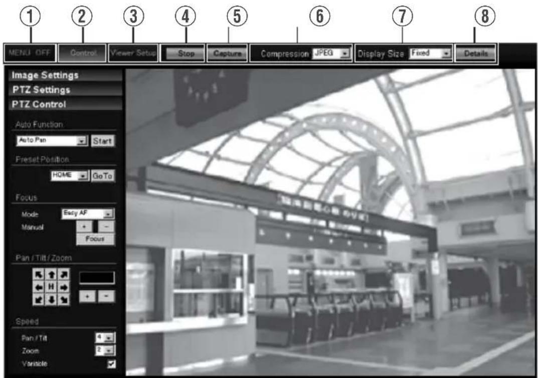
| 1MENU OFF MENU ON | For showing/hiding the operation menu. |
| 2Control | Switches to the PTZ menu. Click this button when you want to perform “Image Settings”, “PTZ setting” or “PTZ Control”. (Page 104) |
| 3Viewer Setup | Switches to the viewer settings menu.Click this button when you want to configure the settings of “JPEG Viewer Settings”, “MPEG4 Viewer Settings” or “Operator Password”. |
| 4Capture | Captures the currently displayed image on the computer. The captured data is recorded as a JPEG file in the folder that is created under [My Documents] of the computer.The default folder name is “VN-V685”(VN-V685U) or “VN-V686B”(VN-V686BU/VN-V686WPBU).The file name is made up of the year, month, day, hour, minute, second, and millisecond.Memo:In the case of Windows Vista, images are stored under [Document].The folder name can be changed. (Page 119)The time indicated is the computer’s clock time, not the clock “Time” of the camera.Motion images cannot be captured.MPEG4 images cannot be captured. |
| 5Stop Pauses/Resumes | playback of images. |
| 6Compression | Switches the stream to acquire. You can specify either JPEG or MPEG4. |
| 7Display Size | For specifying the display size of the image area.[Fixed] : Display according to the window size of the browser.[Variable] : Display according to the specified frame size.Memo:●The window size of the browser does not change when [Fixed] or [Variable] is selected. |
| 8Detalis | Starts up the page for configuring the various detailed settings. |
Memo:
- The settings of Built-in Viewer are stored in the file named Cookie.
This setting screen is used to set Built-in Viewer as a software on the computer, and does not apply to settings of the camera unit. When settings are changed, press the [OK] button to exit and restart the Built-in Viewer.
■Searching and deleting cookie files
- Open [Tool]–[Internet Options]–[Advanced] of the Internet Explorer, and press the [Settings] button under [Temporary Internet Files]. A new [Settings] will appear. Press the [View Files] button in this window. The [Temporary Internet Files] window opens up and a list of files will be displayed. The file named “cgi-bin” in this list is the Cookie for the Built-in Viewer.
- Deleting this file deletes the view settings, and the viewer will be initialized during the next startup.
Built-in Viewer (continued)
Image quality setting
■Image Settings
For adjusting the picture quality.
- When a different menu is currently being displayed, click [Control] to switch the menu.
- Click each menu bar on the left of the screen to open the setting screen.

| 1White Balance | For selecting the white balance control feature. |
| Mode | ATW-Wide: This is the Auto-Tracking White Balance mode (Automatic color temperature tracking). The camera adjusts the white balance automatically according to the color temperature of the illumination. (Color temperature range of 2,300K to 10,000K)ATW-Narrow: This mode supports a narrower range of color temperature than ATW-Wide. (Color temperature range of 3,200K to 8,000K)ATW-Full: ATW is performed in a wider color temperature range.ATW-Sodium: Under the light of a high-pressure sodium lamp, the color is closer to the actual one.AWC: Switches to the Auto-White Balance Control mode. In the “AWC” mode, values entered for the [R Gain] and [B Gain] items are applied to white balance. |
| R Gain | Adjusts the R (red) hue during AWC.[+]: Increases the redness or red level.[-]: Decreases the redness or red level.Memo:Click the [+] or [-] button once to change to the next value. To change the value continuously, click repeatedly. The value will not change if the button remains pressed down. |
| 1White Balance (continued) | |
| B Gain | Adjusts the B (blue) hue during AWC.[+]: Increases the blueness or blue level.[-]: Decreases the blueness or blue level.Memo:Click the [+] or [-] button once to change to the next value. To change the value continuously, click repeatedly. The value will not change if the button remains pressed down. |
| [AWC]button | Executes AWC (automatic white balance control).Execute by placing a white object around the center of the screen in a location with a lighting condition that is similar to the object to be shot.Pressing the [AWC] button replaces the [R Gain] and [B Gain] valueswith the values of the AWC execution results.Even when [White Balance] is set to “ATW-Narrow”, “ATW-Wide”, pressing the [AWC] button switches the mode automatically to AWC. |
| 2Iris | This item sets the iris. |
| Mode | When Auto -1, Auto, or Auto +1 is selected, the iris is adjusted automatically. |
| Manual | You can also adjust using the [+] and [-] buttons. In this case, the iris will change while the button is being pressed. It will stop when the button is released. |
| 3Back Light Compensation | For selecting the backlight compensation feature. Set this feature when there is a bright light source in the same direction as the object. Enables unwanted light sources to be excluded from the photometry area. |
| Mode | Off: No backlight compensation.Area1 to Area4: For selecting a photometry area from the four available types.[Setting value:Off, Area1, Area2, Area3, Area4]Photometry Area Photometry Area Photometry Area Photometry Area Photometry Area     Off Area1 Area2 Area3 Area4Memo:The backlight compensation area is not linked to digital PTZ. Off Area1 Area2 Area3 Area4Memo:The backlight compensation area is not linked to digital PTZ. |
| 4B/W Mode | This sets the function to switch from Color to B&W mode. |
| Mode | Color: Always be in Color mode.Black & White: Always be in B&W mode.Auto: Auto Low,Auto Mid,Auto High: This item automatically switches between Color Mode and B&W Mode when the luminance meets defined conditions for over 30 seconds. Select the sensitivity from three options.[Setting value:Color, Black & White, Auto]Memo:To ensure a successful B&W/Color switchingIf the [B/W Mode] item is set to “Auto Low, Auto Mid, Auto High”, the B&W/Color setting can be switched according to the brightness of the object, but the condition of illumination and field angle may make this impossible. To be absolutely certain of B&W/Color switching, connecting external sensor to alarm input cable of this camera and setting alarm action of B&W mode is recommended. |
Built-in Viewer (continued)
PTZ Setting
■Preset Position
This page describes procedures for setting the preset positions.
- When a different menu is currently being displayed, click [Control] to switch the menu.
- Click the menu bar on the left side of the screen to open the setting screen.
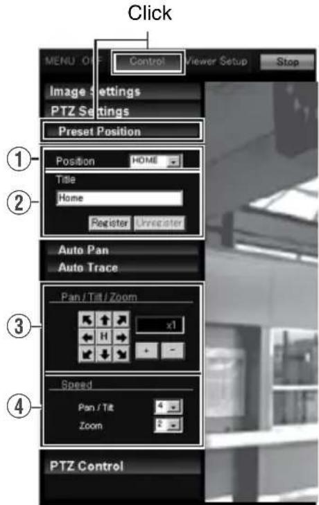
| ■Preset Position For setting the Preset Position. Note: ·When [Auto Flip] is set to “Digital Flip”, preset positions cannot be registered when the tilt angle is more than 90 degrees. [Auto Flip] (Page 71) ·When setting preset positions and [Pan Limit] is “On”, pan operation is unavailable in the prohibited areas. [Pan Limit] (Page 69) ·As moving preset positions has priority over pan limit, set the preset positions when [Pan Limit] is “Off”. After that, when [Pan Limit] is set to “On”, the camera will pan regardless of the prohibited areas. [Pan Limit] (Page 69) ·Items that are stored in the preset position include pan, tilt, zoom, focus, position title, white balance, iris, and backlight compensation. | |
| 1Position For selecting [Position]. [Setting value:HOME, 1 to 99] | |
| 2Title The current title appears. Enter here to register or change the title. (Up to 32 alphanumeric characters can be entered. When JPEG viewer is used, up to 16 alphanumeric characters are displayed.) Memo: ·Click [Unrealiste] button to delete information of the selected position. However, [HOME] cannot be deleted. ·The display area of Home position is set to the full screen by default. | |
| 3Pan /Tilt / Zoom | ■Pan/Tilt operation Click the arrow buttons to move the display area in the direction indicated by the arrow. Release the button to stop the movement. Click the [H] button to move to the home position. ■Zoom operation Use this function to perform zoom operation on the display area. [+] : Zoom is set to TELE and the object becomes bigger. [-] : Zoom is set to WIDE and the object becomes smaller. ■Ratio to Full Area Shows current ratio to full area. Memo: ·You can restrict the magnification of the object using the [+] button by altering the [Zoom Limit] settings. (Page 69) |
| 4Speed This item sets the operation speed. Pan/Tilt : This item sets the operation speed of the [Pan/Tilt] operation button.Increase the number to increase the operation speed. [Setting range: 1 to 8] Zoom : This item sets the operation speed of the [Zoom] operation button.Increase the number to increase the operation speed. [Setting range: 1 to 4] | |
Built-in Viewer (continued)
PTZ Setting (continued)
Auto Pan
For setting the Auto Pan.
- When a different menu is currently being displayed, click [Control] to switch the menu.
- Click the menu bar on the left side of the screen to open the setting screen.

![graph TD A["User"] -->|Data Flow| B["Server"] B -->|Data Flow| C["Storage Unit"] C -->|Data Flow| A style A fill:#f9f,stroke:#333 style B fill:#ccf,stroke:#333 style C fill:#cfc,stroke:#333](/content/2026/06/1352302/images/34a0e357dbebf741fdf4dc67d80ad138024313e728ee219ccbcff99c6989d068.jpg)
| ■ Auto Pan | This item sets the Auto Pan operation which moves at a specific speed from the preset [Start]. |
| 1Mode | Select the [Mode] of the Auto Pan operation.Right: This rotates the camera horizontally in the right direction from the [Start Position].Left: This rotates the camera horizontally in the left direction from the [Start Position].Return: Moves between [Start Position] and [Start Position] in the clockwise direction from the [Start Position] toward the [Return Position].You can specify any random position as the start and return positions except under the following conditions.Tilt angle of 90° or larger: An error message appears if the angle is set to 90° or larger.Electronic zoom area: When setting is performed using the electronic zoom area, optical zoom is automatically set to its largest magnification ratio.Memo:●If the zoom ratio between the [Start Position] and [Return Position] is different from each other, linked operations between zoom and pan/tilt may not be even. |
| 1Speed Select the Auto Pan operation speed.[Setting value:Low, Mid, High] | |
| 2Start Position Return Position | Select the [Start Position] and [Return Position] (only during “Return”) of the operation. Operate the camera manually, decide on a position and click [Apply] to register. Click [Go To] to move the camera to the registered position.Memo:● For details on the manual operation, see [PTZ Control] (Page 113). |
Built-in Viewer (continued)
PTZ Setting (continued)
■Auto Trace
For setting the Auto Trace.
- When a different menu is currently being displayed, click [Control] to switch the menu.
- Click the menu bar on the left side of the screen to open the setting screen.
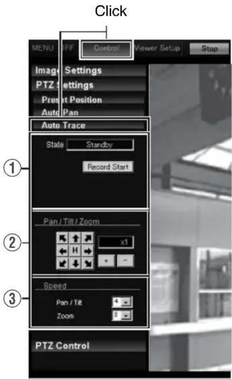
| ■ Auto Trace | This item stores and reproduces manual operation.Note:As Auto Trace performs simple saving of manual operation, the position may be shifted during playback.Digital Flip cannot be used during Auto Trace recording. . |
| 1 State | [Record Start] : The camera will start recording of Pan/Tilt and Zoom operations. (for approximately 30 seconds)[Record Stop] : Click this when a recording operation is complete.Memo:For details on the manual operation, see [PTZ Control] (Page 113).[State] DisplayThe current status is displayed.Standby : The camera is on standby. [Record Stop] is invalid.Recording : The camera is recording. Click [Record Stop] to finish recording. “Completed” will be displayed.Completed : Recording is completed. After “Completed” is displayed for 3 seconds, “Standby” will be displayed.Timeout : 30 seconds has passed since recording started.(Operation for the 30 seconds has been recorded.) After “Timeout” is displayed for 3 seconds, “Standby” will be displayed.Memory Full : The operation has exceeded the number of recordable operations. Further recording cannot be made even if it is within 30 seconds. (Operations before the limit are recorded.) After “Memory Full” is displayed for 3 seconds, “Standby” will be displayed. |
| 2 Pan /Tilt /Zoom | ■ Pan/Tilt operationClick the arrow buttons to move the display area in the direction indicated by the arrow. Release the button to stop the movement.Click the [H] button to move to the home position.■ Zoom operationUse this function to perform zoom operation on the display area.[+]: Zoom is set to TELE and the object becomes bigger.[-]: Zoom is set to WIDE and the object becomes smaller.■ Ratio to Full AreaShows current ratio to full area.Memo:You can restrict the magnification of the object using the [+] button by altering the [Zoom Limit] settings. (Page 69) |
| 3 Speed | This item sets the operation speed.Pan/Tilt : This item sets the operation speed of the [Pan/Tilt] operation button.Increase the number to increase the operation speed.[Setting range:1 to 8]Zoom : This item sets the operation speed of the [Zoom] operation button.Increase the number to increase the operation speed.[Setting range: 1 to 4] |
Built-in Viewer (continued)
PTZ Control
PTZ Control
Use this item to operate the PTZ feature.
- When a different menu is currently being displayed, click [Control] to switch the menu.
- Click the menu bar on the left side of the screen to open the setting screen.

| ■ PTZ Control | For operating the camera and adjusting the angle and image quality of the position to be registered. |
| 1Auto Function | For selecting the operation.[Start] : Start the selected Auto function.[Stop] : Stop the running Auto function.Memo:When “Auto Patrol” is selected, the patrol mode list is displayed.When “Intelligent Tracking” is selected, the target’s list is displayed. |
| Auto Pan : The configured Auto Pan operation is performed.(Page 109)Auto Patrol : The configured Auto Patrol operation is executed. Select “Auto Patrol”.(Page 72)Auto Trace :The configured Auto Trace operation is performed.(Page 111)Auto Tracking : Auto tracking is performed. (Page 67)Motion detection does not work during Auto Tracking.Intelligent Tracking: Intelligent tracking is performed. (Page 116)Note:When the [Mode] item of [Auto Return] is set to “Auto Patrol” and Auto Patrol starts in this screen, the “Auto Patrol” mode of [Auto Return] will be changed to the mode that was started in this screen. [Auto Return](Page 66)When “Auto Pan” starts, the camera will repeat the left rotate, right rotate or return operations.When “Auto Patrol” starts, the camera will complete a series of operations and return to the start position, and then repeat the entire process. When Auto Trace starts, the camera will perform a series of operations before returning to the start position. It will resume after 30 seconds. If Auto Return function is set, the Auto function that was started manually is stopped when “Auto Return” starts. | |
| 2Preset Position | For selecting the preset position. When the selected position has been registered, the camera will move to the selected position.[Setting range: HOME, 1 to 19] |
Built-in Viewer (continued)
PTZ Control (continued)
| ■PTZ Control (continued) | |
| 3Focus | This item adjusts the focus.Mode : Shows the current mode.Easy AF : Auto Focus (AF) will activate automatically when the pan, tilt or zoom function is operated manually. This is convenient as you need not reset the focus everytime you move the camera when there are many manual operations.Manual : Click the [+], [-] buttons to adjust manually. The focus will change while the button is being pressed. It will stop when the button is released.[Focus] button : Click this button to focus automatically in about 1 secondMemo: ·The “Easy AF” function may not focus properly for some objects. In this case, set the focus manually. |
| 4Pan /Tilt / Zoom | ■Pan/Tilt operationClick the arrow buttons to move the display area in the direction indicated by the arrow. Release the button to stop the movement.Click the [H] button to move to the home position.■Zoom operationUse this function to perform zoom operation on the display area.[+] : Zoom is set to TELE and the object becomes bigger.[-] : Zoom is set to WIDE and the object becomes smaller.■Ratio to Full AreaShows current ratio to full area.Memo: ·You can restrict the magnification of the object using the [+] button by altering the [Zoom Limit] settings. (15 Page 69) |
| 5Speed This item | sets the operation speed.Pan/Tilt : This item sets the operation speed of the [Pan/Tilt] operation button.Increase the number to increase the operation speed.[Setting range: 1 to 8]Zoom : This item sets the operation speed of the [Zoom] operation button.Increase the number to increase the operation speed.[Setting range: 1 to 4]Variable Speed : This function adjusts the Pan/Tilt operation speed by the zoom ratio. Select the checkbox to slow down at the Tele end and to move quickly at the Wide end. Deselect the checkbox to move the camera at a constant speed configured in Pan/Tilt regardless of the zoom ratio. |
■Intelligent Tracking feature
Use this item to operate the Intelligent Tracking feature.
- When a different menu is currently being displayed, click [Control] to switch the menu.
- Click each menu bar on the left of the screen to open the setting screen.

Built-in Viewer (continued)
PTZ Control (continued)
| ■Intelligent Tracking | Click on the object on the viewer screen to shoot the selected object by tracking its color information. |
| Memo:●You can change the object to track freely by clicking the object when “Locked” or “Losing” is displayed.●You can select whether to display the [Tracking Frame] (JPEG Viewer only) and [Tracking Status] displays on the setting screen. (Page 118)(Page 121) | |
| Note:●When the OS of the computer is WindowsXP, click the viewer screen once to activate the screen before clicking on the object to track. | |
| 1For selecting [Intelligent Tracking].2Click [Start].●Intelligent Tracking switches to the standby mode, and Standby is shown on the top right corner of the viewer screen. (JPEG Viewer)●Intelligent Tracking switches to the standby mode, and Standby is shown in the title bar. (MPEG4 Viewer)3Click on the object to track on the viewer screen.●The object is surrounded by [Tracking Status] (blue frame). (JPEG Viewer only)●When an object is being captured, “Locked” appears on the top right corner of the viewer screen. When the camera loses track of the object, this appears as “Losing”. (JPEG Viewer)●When an object is being captured, “Locked” appears in the title bar. When the camera loses track of the object, this appears as “Losing”. (MPEG4 Viewer) |
JPEG Viewer Settings
Using the compressed JPEG format enables display of a series of still images as well as one-shot recording of still images.
When the JPEG Viewer is first installed, it is set to play back at 15 fps by default.
- When a different menu is currently being displayed, click [Viewer Setup] to switch the menu.
- Click each menu bar on the left of the screen to open the setting screen.
■On Screen Display

Stream

Other

| ■On Screen Display Settings | For setting display items on the viewer screen.For the JPEG Viewer, characters are displayed as overlay on the video image. |
| 1Camera ID | Select “On” to display [Camera ID]. (Up to 16 alphanumeric characters will be displayed.)[Camera ID] can be specified on the [Basic Settings2] or [Camera] page.(Page 51) |
| 2PositionTitle | Select “On” to display the PositionTitle. |
| 3Display MD | Selecting “On” displays the area in which motion is detected in red. |
| 4Tracking Frame | When “On” is selected, the blue frame that surrounds the tracked object of “Intelligent Tracking” appears on the screen. (Page 116) |
| 5Tracking Status | When “On” is selected, the “Intelligent Tracking” status appears as “Standby”, “Locked”, or “Losing” on the screen. (Page 116) |
| 6Time | Select “On” to display the time.This indicates the time that is stored in the JPEG data. |
| 7Format Select the format for displaying time.YYYY, MM, and DD denote year, month and day respectively, while HH, MM, and SS denote hour, minute and second respectively. mm is equivalent to 1/100 seconds. | |
Built-in Viewer (continued)
JPEG Viewer Settings (continued)
| Stream | For specifying settings for receiving JPEG stream. | |
| 1 Stream | For selecting the protocol when the viewer acquires data from the camera.When “HTTP” is selected, lost packets are recovered via resending. Camera may be monitored using multiple viewers when “Multicast” is selected. When playing back via multicast, start multicast sending on the [Streaming] page.[Streaming Page] (Page 82)Note:When Built-in Viewer is launched with “Multicast” specified, a Windows firewall warning may appear. In this case, select “unblock” and proceed.If “block” is selected, the Windows firewall will block the multicast stream and playback of “Multicast” by the viewer will fail. | |
| 2 HTTP Port You can | change the HTTP port number.The default port number setting is “80”.Specify the same value as the parameter that is set on the [Protocol] page of the camera. (Page 81) | |
| 3 Frame Rate | For selecting the acquisition frame rate of the viewer.Selecting a large frame rate will increase the processing load of the computer on which the viewer is running.[Setting values:30, 25, 15, 10, 7.5, 6, 5, 3, 2, 1, 1/2, 1/3, 1/5, 1/10, 1/15, 1/20, 1/30, 1/60]Note:Set to a rate such that the CPU burden of the computer does not exceed 80%. If the CPU is overloaded, the computer may not function properly. | |
| 4 Multicast IP Address | You can change the multicast IP address.The default IP address setting is “225.0.1.1”. | |
| 5 Multicast Port | You can change the multicast port number.The default port number setting is “49152”.Memo:This is enabled when [Start] is selected for the[JPEG] [Control] item on the [Streaming] page.Specify the same value as the parameter that is set on the [Streaming] page of the camera. (Page 82) | |
| Other | ||
| 1 Folder Name | For specifying the name of the folder in which the captured files are stored. (When the viewer is installed: “VN-V685”(VN-V685U),“VN-V686B”(VN-V686BU/VN-V686WPBU) | |
MPEG4 Viewer Settings
Using the compressed MPEG4 format enables display of MPEG4-encoded motion images.
- When a different menu is currently being displayed, click [Viewer Setup] to switch the menu.
- Click each menu bar on the left of the screen to open the setting screen.
Memo:
- To use the MPEG4 Viewer of the camera, install the open source codec "ffdshow". You can download "ffdshow" from the Internet.
Title Bar

Stream

Built-in Viewer (continued)
MPEG4 Viewer Settings (continued)
| ■Title Bar | For setting display items on the viewer screen.For the MPEG4 Viewer, characters are displayed in the title bar of the window. | |
| 1Camera IDSelect “On” to display [Camera ID]. (Up to 16 alphanumeric characters will be displayed.) [Camera ID] can be specified on the [Basic Settings2] or [Camera] page. (Page 51) | ||
| 2Position TitleSelect “On” to display the title of the position that is being displayed. | ||
| 3Tracking FrameWhen “On” is selected, the “Intelligent Tracking” status appears as “Standby”, “Recording”, or “Completed” on the screen. (Page 69). | ||
| 4TimeSelect “On” to display the time. | ||
| 5FormatSelect the format for displaying time.YYYY, MM, and DD denote year, month and day respectively, while HH, MM, and SS denote hour, minute and second respectively. mm is equivalent to 1/100 seconds. | ||
| ■Stream | For specifying settings for receiving MPEG4 stream. | |
| 1StreamFor selecting the protocol when the viewer acquires data from the camera.When “HTTP” is selected, lost packets are recovered via resending. Camera may be monitored using multiple viewers when “Multicast” is selected.Memo:When playing back via multicast, start multicast sending on the [Streaming] page of the camera unit.[Streaming Page] (Page 82)Note:When Built-in Viewer is launched with “Multicast” specified, a Windows firewall warning may appear. In this case, select “unblock” and proceed.If “block” is selected, the Windows firewall will block the multicast stream and playback of multicast by the viewer will fail. | ||
| 2HTTP PortYou can change the HTTP port number.The default port number setting is 80.Specify the same value as the parameter that is set on the [Protocol] page of the camera. (Page 81) | ||
| 3Multicast IP AddressYou can change the multicast IP address.The default address is 225.0.2.1. | ||
| 4Multicast PortYou can change the multicast port number.The default port number setting is 59152.Memo:This is enabled when “Start” is selected for the [JPEG Control] item on the [Streaming] page.Specify the same value as the parameter that is set on the [Streaming] page of the camera. (Page 82) | ||
Operator Password
This section describes the procedures for configuring the Operator Password, which is required for PTZ operation.
- When a different menu is currently being displayed, click [Viewer Setup] to switch the menu.
- Click the menu bar on the left side of the screen to open the setting screen.

| ■Operator Password | For configuring the Operator Password required for PTZ operation. | |
| 1OperatorPassword | Enter the Operator Password. | |
Built-in Viewer (continued)
Exiting the Viewer
To exit, press the [X] button at the top right of the window.

- During the next startup of Built-in Viewer, launch the Internet Explorer and enter the URL of the camera in the address field.
For example, if the IP address of the camera is 192.168.0.2, enter as follows:
http://192.168.0.2/
Memo:
- After the [Security Settings] screen appears, press the [OK] button to proceed.
Troubleshooting
| Symptom Causes and Countermeasures | Reference Page | |
| Video image does not appear Power does not turn on. | Is there a problem with the power cable connecting this unit and the power unit? (If the power cable is too long or thin, the cable resistance will be high and the correct voltage may not be supplied.)→Use a cable of low resistance and the correct cable length. (When the camera is operating (at rated current), check that the supplied voltage is of the rated voltage at the terminal of the camera.) | Page 23Page 30 |
| Is the lens cap attached?→Remove the lens cap. | Page 21Page 26 | |
| The power of the camera turns off when VN-V686WPBU is used in an environment under -10°C. | When power is supplied using PoE, the heater will not work. Use an AC 24 V power supply when using VN-V686WPBU in an environment under -10°C. | Page 30 |
| The power does not turn on even when PoE is used to supply power. | With some PoE-compatible devices (such as a hub), power will not be supplied when connected to a certain number of PoE terminals which exceed the limit of total electrical power that can be supplied. Please refer to the instruction manual of PoE-compatible devices. | |
| IP address of the camera is unknown | The default IP address is 192.168.0.2, and the default Subnet Mask is 255.255.255.0.When [IP Setting] is set to “DHCP Enable”, this product will run using the default IP address when it is started up via a LAN in which a DHCP server does not exist.Search tool in attached CD-ROM is available to look for the camera using a PC in the same LAN. | Page 40 |
| The web page of the camera cannot be displayed | Check the Internet Explorer settings.When a proxy server is in use, configure the proxy server settings of the Internet Explorer accordingly. | Page 44 |
| Built-in Viewer cannot be installed | Check the Internet Explorer settings.Built-in Viewer consists of a software component called ActiveX.The ActiveX is usually installed when Built-in Viewer is used for the first time. However, installation may be rejected depending on the Anti-virus software settings. In this case, change the settings of the Anti-virus software before installing Built-in Viewer. | Page 102 |
| Authentication by VeriSign appears during installation of Built-in Viewer | VeriSign's electronic signature is stored in Built-in Viewer. For computers with a network environment that is connected to the Internet, the authenticity of the Built-in Viewer can be verified via authentication by VeriSign. | — |
| Multicast images cannot be played back | Start multicast transmission manually from the [Streaming] page of the camera.In the case of multicast reception at Built-in Viewer, check that the multicast address and port number of Built-in Viewer settings coincide with those on the [Streaming] page of the camera.Make use of a network that supports IGMP v2 for multicast transmission.Data may be blocked by the Windows firewall. When this occurs, perform the following to allow it to pass through.Windows XP:Double-click [Windows Firewall] under [Start]–[Control Panel], click the [Add Port...] button under the Exception tab, and register the port number to be allowed through the firewall in the Port Number field. Enter an arbitrary character string in the name field.Windows XP:Double-click [Allow a program through Windows Firewall.] under [Start]–[Control Panel]–[Windows Firewall], click the [Add Port...] button under the Exception tab, and register the port number to be allowed through the firewall in the Port Number field. Enter an arbitrary character string in the name field. | Page 82Page 119Page 121 |
| The frame rate of the displayed image is low | Check Built-in Viewer settings when a Built-in Viewer is in use.Frame rate will be constrained when the network bandwidth is narrow. | Page 57Page 82Page 33 |
| A white zone appears in Built-in Viewer | For some computers, a part of the Internet Explorer graphics may not appear and is left white when the following setting is performed on the Internet Explorer.If [Right-click on the Desktop screen]–[Properties]–[Settings]–[Advanced]–[Advanced]–[DPI setting] is set to "Large size" or "Custom size", select "Normal size(96DPI)" to resume normal drawing. | — |
| A warning message appears upon starting up Built-in Viewer | Built-in Viewer consists of a software component called ActiveX.The ActiveX is usually installed when Built-in Viewer is used for the first time. However, installation may be rejected depending on the Anti-virus software settings. In this case, change the settings of the Anti-virus software before installing Built-in Viewer. | — |
| TCP images cannot be played back | The maximum number of images that can be sent by the camera via TCP is 20, and up to 20 Built-in Viewers can be connected to each camera unit.Make use of multicast for monitoring when the number of areas exceeds the above number.Camera allows multicast transmission of JPEG and MPEG4 one stream at a time. | Page 33 |
| Unable to receive alarm notification using the computer via TCP/UDP | ●Data may be blocked by the Windows firewall.When this occurs, perform the following to allow it to pass through.Windows XP:Double-click [Windows Firewall] under [Start]-[Control Panel], click the [Add Port...] button under the Exception tab, and register the port number to be allowed through the firewall in the Port Number field. Enter an arbitrary character string in the name field.Windows XP:Double-click [Allow a program through Windows Firewall.] under [Start]-[Control Panel]-[Windows Firewall], click the [Add Port...] button under the Exception tab, and register the port number to be allowed through the firewall in the Port Number field. Enter an arbitrary character string in the name field. | — |
| Power is turned on but it is disconnected once the camera rotates. | Are the transporting tape and cushioning material removed?→Remove the transporting tape and cushioning material. | Page 21Page 26 |
| Characters of the file name registered in the FTP server are garbled | When double-byte characters are to be used for the file name, make use of an FTP server for which the character code is EUC-JP. | Page 63 |
| The MPEG4 Viewer screen appears in black | Is ffdshow installed?To use the MPEG4 Viewer of the camera, install the open source codec “ffdshow”. You can download “ffdshow” from the Internet. | — |
| “Caution : The fan(T) is stopped” appears on the screen. (※ denotes number) | The internal cooling fan is abnormal.Write down the displayed text of →“Caution : The fan(T) is stopped” and consult your nearest JVC dealer. Turn off the power of this camera beforehand. | — |
| The camera pans automatically | When [Auto Cleaning] is set to “On”, this is not an abnormality. Check the settings. | Page 89 |
Specifications
VN-V685U/VN-V686BU
CAMERA HEAD
Image pickup device: 1/4 type, Interline Transfer CCD 768 (H) x 494 (V)
Minimum brightness of object
Color : 1.0 lx (50 % output, AGC Super, WIDE edge, Monitor Type CRT, Black Level 2) 0.5 lx (25 % output, AGC Super, WIDE edge, Monitor Type CRT, Black Level 2)
During B&W : 0.08 lx (50 % output, AGC Super, WIDE edge, Monitor Type CRT, Black Level 2) 0.04 lx (25 % output, AGC Super, WIDE edge, Monitor Type CRT, Black Level 2)
White balance : Select from ATW-Narrow/ATW-Wide/AWC
Electronic Shutter : 1/60, 1/100, (50 Hz Flickerless), 1/250, 1/500, 1/1000, 1/2000, 1/4000, 1/10000
Backlight Compensation
: 4 photometry areas can be selected
Color level adjustment
: YES
Contour adjustment : Effective for both horizontal and vertical (adjustable level)
Network section
Image compression format
: JPEG, MPEG 4
Frame size : 640
× 480,320 × 240
Network interface
: 100BASE-TX/10BASE-T/FULL/HALF/Auto negotiation supported
Internal memory : 8 MB
■ LAN Specifications
Compliant with IEEE802.3 and IEEE802.3u
Communication protocol
: TCP/IP, UDP, HTTP, FTP, ICMP, ARP, DHCP, SNTP, SMTP, DSCP, IGMP
Lens (VN-V685U)
Zoom ratio : Approx. 27 times
Focal length : 3.43 mm to 92.6 mm
Maximum aperture ratio
: F1.6 (WIDE) to F3.5 (TELE)
Aperture range : F1.6 (Opened fully) to Equivalent to F360
Maximum close-range
: Approx. 1.8 m (TELE) Approx. 0.6 m (WIDE)
Lens (VN-V686BU)
Zoom ratio : Approx. 36 times
Focal length : 3.43 mm to 122 mm
Maximum aperture ratio: F1.6 (WIDE) to F4.5 (TELE)
Aperture range : F1.6 (Opened fully) to Equivalent to F360
Maximum close-range
: Approx. 1.8 m (TELE) Approx. 0.6 m (WIDE)
■ Rotation platform
Horizontal rotation range
: 360 °Endless rotation
Horizontal rotation speed
: Approx. 0.04 °/s to Approx. 400°/s
Vertical rotation range
: -5° to 185° (Horizontal to Face bottom to Horizontal)
Vertical rotation speed
: Approx. 0.04 °/s to Approx. 400°/s
Overall
Alarm input
: No-voltage a contact input, NPN open collector input, low level, latch/momentary (200 ms and above) (Circuit current during low level: 1 mA; Applied voltage during high level: DC 3.3 V)
Alarm output
: NPN open collector output (Allowable applied voltage:DC20 V; Allowable inflow current: 25 mA)
Supply voltage
: AC 24 V 50 Hz/60 Hz or PoE(DC - 48 V)
Current consumption: AC 24 V 1.2 A
Power consumption : PoE 12.95 W
Number of preset positions
: Up to 100
Surrounding temperature
: - 1 °C to 50 °C (operation) 0 °C to 40 °C (Recommended)
Ambient humidity
: 20 % RH to 90 % RH (without condensation)
Mass : Approx. 1.9 k
g
■Accessories
: Read Me First .... 1
CD-ROM 1
Ceiling Mount 1
Dome Cover 1
Template 1
Wire Clamp 1
Warranty Card (For USA).... 1
Service Information Card (For USA) ... 1
■Dimension [Unit: mm]

■Ceiling mounting hole [Unit: mm]

* Specifications and appearance of this unit are subject to change for further improvement without prior notice.
Specifications (continued)
VN-V686WPBU
CAMERA HEAD
Image pickup device: 1/4 type, Interline Transfer CCD 768 (H) x 494 (V)
Minimum brightness of object
Color : 1.0 lx (50 % output, AGC Super, WIDE edge, Monitor Type CRT, Black Level 2) 0.5 lx (25 % output, AGC Super, WIDE edge, Monitor Type CRT, Black Level 2)
During B&W : 0.08 lx (50 % output, AGC Super, WIDE edge, Monitor Type CRT, Black Level 2) 0.04 lx (25 % output, AGC Super, WIDE edge, Monitor Type CRT, Black Level 2)
White balance
: Select from ATW-Narrow/ATW-Wide/AWC
Electronic Shutter : 1/60, 1/100, (50 Hz Flickerless), 1/250, 1/500, 1/1000, 1/2000, 1/4000, 1/10000
Backlight Compensation
: 4 photometry areas can be selected
Color level adjustment
: YES
Contour adjustment : Effective for both horizontal and vertical (adjustable level)
Network section
Image compression format
: JPEG, MPEG 4
Frame size : 640 × 480
320×240
Network interface : 100BASE-TX/10BASE-T/FULL/HALF/Auto negotiation supported
Internal memory : 8 MB
■ LAN Specifications
Compliant with IEEE802.3 and IEEE802.3u
Communication protocol
: TCP/IP, UDP, HTTP, FTP, ICMP, ARP, DHCP, SNTP, SMTP, DSCP, IGMP
Lens
Zoom ratio : Approx. 36 times
Focal length : 3.43 mm to 122 mm
Maximum aperture ratio
: F1.6 (WIDE) to F4.5 (TELE)
Aperture range : F1.6 (Opened fully) to Equivalent to F360
Maximum close-range
: Approx. 1.8 m (TELE) Approx. 0.6 m (WIDE)
■ Rotation platform
Horizontal rotation range
: 360 °Endless rotation
Horizontal rotation speed
: Approx. 0.04 °/s to Approx. 400°/s
Vertical rotation range
: -5° to 185° (Horizontal to Face bottom to Horizontal)
Vertical rotation speed
: Approx. 0.04 °/s to Approx. 400°/s
Overall
Alarm input
: No-voltage a contact input, NPN open collector input, low level, latch/momentary (200 ms and above) (Circuit current during low level: 1 mA; Applied voltage during high level: DC 3.3 V)
Alarm output
: NPN open collector output (Allowable applied voltage:DC20 V; Allowable inflow current: 25 mA)
Number of preset positions
: Up to 100
Supply voltage
: AC 24 V 50 Hz/60 Hz or PoE(DC - 48 V)
Current consumption
AC 24 V power supply
: AC 24 V 2.2 A,
Power consumption
PoE power supply
: PoE 12.95 W
Surrounding temperature
- When heater is in use
:-40 °C to 50 °C (operation)
-30°C to 40°C (recommended)
* Connect to AC 24 V when using the heater.
※ If the temperature is between -40°C to -20°C when power is turned on, images may not be displayed until the heater takes effect (about 2 hours).
- When heater is not in use
:-10 °C to 50 °C (operation)
0°C to 40°C (recommended)
Ambient humidity
: 20 % RH to 90 % RH
(without condensation)
Dust-proof, Waterproof
: IP66 (IEC60529)
Mass : Approx. 5.5 k
g
■Accessories
: Read Me First .... 1
CD-ROM 1
Warranty Card (For USA)...... 1
Service Information Card (For USA) ... 1
RJ-45 Conversion Connector.... 1
SILICA GEL 3
■Dimension [Unit: mm (inch)]

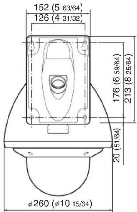

※ Specifications and appearance of this unit are subject to change for further improvement without prior notice.
OUTDOOR PTZ IP DOME CAMERA
UN-V686WPBU
PTZ IP DOME CAMERA
UN-UN-UN-UN
JVC


- FOR CUSTOMER USE
- SAFETY PRECAUTIONS
- ATTENTION
- INFORMATION FOR USERS ON DISPOSAL OF OLD EQUIPMENT
- [EUROPEAN UNION]
- (BUSINESS USERS)
- [OTHER COUNTRIES OUTSIDE THE EUROPEAN UNION]
- FOR USA AND CANADA
- CAUTION
- INFORMATION FOR USA
- WARNING (FOR EUROPE)
- FOR USA-CALIFORNIA ONLY
- DEAR CUSTOMER
- IMPORTANT SAFEGUARDS
- CONTENTS
- GETTING STARTED
- CONNECTION/INSTALLATION (VN-V685U/VN-V686BU)
- CONNECTION/INSTALLATION (VN-V686WPBU)
- NETWORK SETTING
- SETTING USING INTERNET EXPLORER
- OPERATION
- OTHERS
- MAIN FEATURES
- SUPPORT FOR POE (POWER OVER ETHERNET)
- DUAL STREAM FULL FRAME RATE TRANSMISSION
- REALIZING A HIGH PICTURE QUALITY
- PROGRESSIVE OUTPUT
- LONG MAGNIFICATION ZOOM LENS
- EQUIPPED WITH HIGH PRECISION HIGH SPEED ROTATION PLATFORM
- IMAGE STABILIZER
- AUTOMATIC TRACKING FUNCTION
- INTELLIGENT TRACKING FEATURE
- DAY/NIGHT SURVEILLANCE
- PRIVACY MASK FUNCTION
- MOTION DETECTION FEATURE
- SUPPORT FOR MULTICAST
- SUPPORT FOR IPV6 DUAL STACK
- HTTP-BASED API
- BUILT-IN INTEGRATED VIEWER SOFTWARE
- WATERPROOF AND WEATHERPROOF CHASSIS (VN-V686WPBU)
- THIS MANUAL CONTAINS THE DETAILED INSTRUCTIONS FOR USING THIS UNIT
- HOW TO READ THIS MANUAL
- SYMBOLS USED IN THIS MANUAL
- CONTENTS OF THIS MANUAL
- MOUNTING TO A FIRM PLACE
- MOUNTING THE CAMERA CORRECTLY WITH THE DESIGNATED CLAMPING BRACKETS
- USING THE CORRECT POWER AND VOLTAGE
- INSPECT THE UNIT REGULARLY
- OPERATING ENVIRONMENT
- RECOMMENDED COMPUTER SPECIFICATIONS
- LAN ENVIRONMENT
- MEMO
- PRECAUTIONS
- STORAGE AND OPERATING ENVIRONMENT
- PRECAUTIONS (CONTINUED)
- OTHERS (CONTINUED)
- TRANSPORTING THE UNIT
- COPYRIGHT PROTECTION
- MAINTENANCE
- SAVING ENERGY
- DISCLAIMER
- TRANSPORTATION
- CONSUMABLE PARTS
- AUTO FOCUS
- ZOOM OPERATION
- PRESET POSITIONS
- NAME AND FUNCTION OF PARTS
- VN-V685U/VN-V686BU
- CEILING MOUNT SECTION
- ① FIXING HOLES (X3)
- ② [AC24V\~INPUT] AC 24 V INPUT TERMINAL
- ③ [10BASE-T/100BASE-TX] LAN CABLE CONNECTION TERMINAL
- ALARM INPUT/ALARM OUTPUT TERMINAL
- ⑤ FALL PREVENTION WIRE FIXING BRACKET
- ⑥ WIRE CLAMP FIXING HOLE
- ⑦ FALL PREVENTION WIRE MOUNTING HOLE
- POWER INDICATOR
- ⑨ [MAC ADDRESS] INDICATION
- ⑩ CAMERA CONNECTION TERMINAL (FEMALE)
- NAME AND FUNCTION OF PARTS (CONTINUED)
- ⑪ FALL PREVENTION WIRE
- ⑫CAMERA LOCK KNOB (X2)
- FRONT MASK
- LENS
- ⑮CABLE COVER
- ⑯DOME COVER
- NOTE
- VN-V686WPBU
- FRONT SIDE
- FEATURES
- SURVEILLANCE USING BUILT-IN VIEWER
- MONITORING VIA MULTICAST
- SAVING JPEG IMAGES TO THE FTP SERVER AT REGULAR INTERVALS
- ALARM
- RESTRICTIONS ON CLIENTS
- CONTROL VIA CUSTOMIZED APPLICATION SOFTWARE
- MOUNTING THE CAMERA
- PREPARATION
- MAKE HOLES ON THE CEILING
- PULL THE CABLES FROM THE HOLE IN THE CEILING
- REMOVE THE CEILING CLAMPING BRACKET FROM THE CAMERA UNIT
- REMOVE THE TERMINAL COVER
- MOUNT THE FALL PREVENTION WIRE THAT CONNECTS THE CEILING CLAMPING BRACKET TO THE CEILING
- CONNECT THE CABLE (23 TO 25)
- HANDLING CABLES
- MOUNTING THE CAMERA (CONTINUED)
- PREPARATION (CONTINUED)
- MOUNT THE TERMINAL COVER
- PULLING OUT THE CABLES FROM THE SIDE
- PULLING OUT THE CABLES FROM THE TOP
- MOUNTING THE CEILING CLAMPING BRACKET TO THE CEILING
- SECURE THE CEILING CLAMPING BRACKET TO THE CEILING
- MOUNTING THE CAMERA TO THE CEILING
- MOUNT THE DOME COVER TO THE CAMERA
- REMOVE THE DOME COVER PROTECTIVE SHEET
- MOUNT THE FALL PREVENTION WIRE
- MOUNT THE CAMERA
- CHECK THAT THE CAMERA FIXING LOCK KNOBS (X2) ARE STICKING OUT
- LOCK
- REMOVE THE SAFETY PRECAUTIONS SHEET ON THE CAMERA
- REMOVING THE CAMERA
- POWER CONNECTION
- CONNECTING TO AN AC 24 V POWER SUPPLY
- WARNING
- POWER CONNECTION (CONTINUED)
- USING POE
- WHAT IS POE (POWER OVER ETHERNET)
- CABLE TO USE
- LAN CABLE CONNECTION
- CONNECTING THE ALARM SIGNAL TERMINAL
- ALARM INPUT SIGNAL
- ALARM OUTPUT SIGNAL
- RATING
- SETTING UP THE WALL
- MAKE HOLES IN THE WALL
- INSTALL THE ANCHOR BOLTS FOR MOUNTING THE CAMERA
- INSTALL THE ANCHOR BOLT FOR MOUNTING THE FALL PREVENTION WIRE
- PULL THE CABLES FROM THE HOLE IN THE WALL
- SETTING UP THE CAMERA
- REMOVE THE DOME COVER
- REMOVE THE CUSHIONING MATERIAL, LENS CAP AND TAPE USED DURING TRANSPORTING
- INSERT SILICA GEL (WHEN USING POE POWER SUPPLY)
- REMOVE THE CABLE CONNECTION CAP
- PULL OUT THE CABLES FROM THE CABLE CONNECTION HOLE
- PULL OUT THE CABLES (FROM THE WALL) FROM THE CABLE CONNECTION HOLE
- MOUNT THE CAMERA TO THE WALL
- CABLE CONNECTION
- CONNECTING THE POWER CABLE (PAGE 30)
- LAN CABLE CONNECTION (PAGE 31)
- CONNECTING THE ALARM CABLE (PAGE 25)
- MOUNT THE CAP
- CONNECTING THE POWER CABLE
- CONNECTING THE ALARM SIGNAL CABLE
- NETWORK REQUIREMENTS
- ESTIMATION OF TOTAL BIT RATE
- BIT RATE OF JPEG STREAM
- AFS (AVERAGE FILE SIZE)
- VFS(VARIABLE FILE SIZE)
- NETWORK REQUIREMENTS (CONTINUED)
- BIT RATE OF MPEG4 STREAM
- RESTRICTIONS ON THE NUMBER OF DISTRIBUTIONS FOR CAMERA
- INSUFFICIENT NETWORK BANDWIDTH
- NETWORK DELAY
- NETWORK JITTER
- PACKET LOSS
- LIST OF PROTOCOLS AND PORT NUMBERS USED BY THIS UNIT
- IP ADDRESS SETTINGS
- IP ADDRESS SETTING PROCEDURE
- STEP1 IP ADDRESS SETTING AT THE COMPUTER (PAGER37)
- STEP2 INTERNET EXPLORER SETTINGS (PAGER38)
- STEP3 CONNECTING THE CAMERA TO THE COMPUTER (¶PAGER40)
- STEP4 IP ADDRESS SETTING FOR THE CAMERA (PAGER42)
- ●SYSTEM CONFIGURATION REQUIRED FOR SETTING IP ADDRESS
- SET UP THE COMPUTER FOR SETTING THE IP ADDRESS
- ●MINIMUM COMPUTER SPECIFICATIONS FOR SETTING
- IP ADDRESS SETTING AT THE COMPUTER
- CLICK [START]
- WINDOWS VISTA
- THE COMPUTER ON WHICH INTERNET EXPLORER IS LAUNCHED AUTOMATICALLY SELECTS THE CONNECTED NETWORK
- SELECT [INTERNET PROTOCOL(TCP/IP)] AND CLICK [PROPERTIES]
- SET THE IP ADDRESS
- CLICK [OK] ON THE [LOCAL AREA CONNECTION PROPERTISE] SCREEN
- IP ADDRESS SETTINGS (CONTINUED)
- INTERNET EXPLORER SETTINGS
- LAUNCH THE INTERNET EXPLORER ON THE COMPUTER
- WHEN PROXY SETTINGS ARE ENABLED IN THE INTERNET EXPLORER, FOLLOW THE STEPS BELOW TO DISABLE THE PROXY OF THE INTERNET EXPLORER
- IF THE ACTIVE SCRIPT OF THE INTERNET EXPLORER IS DISABLED, FOLLOW THE STEPS BELOW TO ENABLE IT
- IF ACTIVEX CONTROLS AND PLUG-INS OF THE INTERNET EXPLORER IS DISABLED, FOLLOW THE STEPS BELOW TO ENABLE IT
- DISABLE POP-UP BLOCK
- IF PLUG-IN TOOLS ARE INSTALLED IN THE INTERNET EXPLORER, DISABLE THE POP-UP BLOCK FUNCTION OF THESE PLUG-IN TOOLS AS WELL
- CONNECTING THE CAMERA TO THE COMPUTER
- LAUNCH THE INTERNET EXPLORER
- WHEN THE IP ADDRESS OF THE CAMERA IS UNKNOWN
- ENTER THE USER NAME AND PASSWORD (LOGIN AS ADMINISTRATOR) (PAGE 44)
- BUILT-IN VIEWER APPEARS
- THE OPERATOR PASSWORD ENTRY SCREEN APPEARS
- IP ADDRESS SETTING FOR THE CAMERA
- CLICK [ADVANCED SETTINGS] OF THE BUILT-IN VIEWER
- THE [BASIC SETTINGS1] SCREEN APPEARS
- A CONFIRMATION SCREEN APPEARS
- WHEN THE DISPLAY OR CONFIGURATION OF THE OPENED SCREEN APPEARS STRANGE, CHECK THE COMPUTER SETTINGS USING THE FOLLOWING PROCEDURES
- ENTER USER NAME AND PASSWORD
- ●PAGES THAT USERS HAVE ACCESS TO
- USER
- SETTING
- HOW TO OPEN THE SETTING PAGE
- ENTER THE IP ADDRESS OF THE CAMERA IN THE ADDRESS BAR OF INTERNET EXPLORER (PAGE 40)
- CLICK [DETALIS]
- BASIC SETTINGS
- SETTING (CONTINUED)
- CAMERA PAGE
- ENCODING PAGE
- ALARM PAGE
- ALARM ENVIRONMENT PAGE
- PTZ PAGE
- AUTO PATROL PAGE
- PRIVACY MASK PAGE
- MOTION DETECTION PAGE
- NETWORK BASIC PAGE
- NETWORK DETAILS PAGE
- PROTOCOL PAGE
- STREAMING PAGE
- ACCESS RESTRICTIONS PAGE
- TIME PAGE
- PASSWORD PAGE
- MAINTENANCE PAGE
- LIST OF FACTORY SETTINGS OF EACH PAGE
- LIST OF FACTORY SETTINGS OF EACH PAGE (CONTINUED)
- AUTO PATROL PAGE( PAGE 72)
- PRIVACY MASK PAGE(→ PAGE 74)
- MOTION DETECTION PAGE(→ PAGE 76)
- NETWORK BASIC PAGE(PAGE 78)
- NETWORK DETAILS PAGE(→ PAGE 80)
- OPERATION PAGE
- SETTINGS PAGE
- POSITION LIST PAGE
- PATROL SETTINGS PAGE
- BUILT-IN VIEWER
- BUILT-IN VIEWER (CONTINUED)
- SCREEN CONFIGURATION OF BUILT-IN VIEWER
- SEARCHING AND DELETING COOKIE FILES
- IMAGE QUALITY SETTING
- IMAGE SETTINGS
- PTZ SETTING
- PRESET POSITION
- PTZ SETTING (CONTINUED)
- AUTO PAN
- AUTO TRACE
- PTZ CONTROL
- JPEG VIEWER SETTINGS
- MPEG4 VIEWER SETTINGS
- TITLE BAR
- STREAM
- OPERATOR PASSWORD
- EXITING THE VIEWER
- SPECIFICATIONS
- CAMERA HEAD
- NETWORK SECTION
- LAN SPECIFICATIONS
- LENS (VN-V685U)
- LENS (VN-V686BU)
- ROTATION PLATFORM
- OVERALL
- ACCESSORIES
- DIMENSION [UNIT: MM]
- CEILING MOUNTING HOLE [UNIT: MM]
- SPECIFICATIONS (CONTINUED)
- DIMENSION [UNIT: MM (INCH)]
Brand : JVC
Model : VN-V685U
Category : Surveillance Camera