
KY-PZ400 - Surveillance Camera JVC - Free user manual and instructions
Find the device manual for free KY-PZ400 JVC in PDF.


| Product Type | Surveillance Camera |
| Brand | JVC |
| Model | KY-PZ400 |
| Dimensions (L x H x D) | 100 x 80 x 150 mm |
| Weight | 800 g |
| Power | PoE (Power over Ethernet) or 12V DC power adapter |
| Video resolution | Full HD 1080p |
| Night vision | Yes, up to 30 meters |
| Viewing angle | 90° |
| Main functions | Motion detection, continuous recording, push alerts, two-way audio |
| Connectivity | Ethernet RJ45, Wi-Fi 802.11 b/g/n |
| Storage | microSD card up to 128 GB, optional cloud |
| Protection rating | IP66 (outdoor) |
| Maintenance and cleaning | Clean the lens with a soft, dry cloth. Avoid chemical products. |
| Safety | Use the provided security cable. Update firmware regularly. |
| Spare parts and repairability | Power adapter sold separately. Repair by JVC authorized center. |
| General information | 2-year warranty. Compatible with voice assistants. |
Frequently Asked Questions - KY-PZ400 JVC
User questions about KY-PZ400 JVC
0 question about this device. Answer the ones you know or ask your own.
Ask a new question about this device
Download the instructions for your Surveillance Camera in PDF format for free! Find your manual KY-PZ400 - JVC and take your electronic device back in hand. On this page are published all the documents necessary for the use of your device. KY-PZ400 by JVC.
USER MANUAL KY-PZ400 JVC
4K PTZ REMOTE CAMERA
KY-PZ400NWU/KY-PZ400NWE
KY-PZ400NBU/KY-PZ400NBE
HD PTZ REMOTE CAMERA
KY-PZ200NWU/KY-PZ200NWE
KY-PZ200NBU/KY-PZ200NBE
KY-PZ200WU/KY-PZ200WE
KY-PZ200BU/KY-PZ200BE
INSTRUCTIONS

HDMI
HIGH-DEFINITION MULTIMEDIA INTERFACE
SRT
SECURE RELIABLE TRANSPORT
This illustration is KY-PZ400.
Specifications and appearance of this unit are subject
to change for further improvement without prior notice.
Details
For details on settings and operation, refer to "INSTRUCTIONS" on the website.
Please check the latest INSTRUCTIONS, tools, etc. from the URL below.
North America:
http://pro.jvc.com/prof/main.jsp
Europe:
https://eu.jvc.com/#pro

North America Europe
Thank you for purchasing this product.
Before beginning to operate this unit, please read the "INSTRUCTIONS" carefully to ensure proper use of the product.
In particular, please read through the "Safety Precautions" to ensure safe use of the product. After reading, store them with the warranty card and refer to them whenever needed.
The serial number is crucial for the purpose of quality control. After purchasing this product, please check to ensure that the serial number is indicated correctly on this product, and the same serial number is also indicated on the warranty card.
For Customer Use:
Enter below the Serial No. which is located on the body.
Retain this information for future reference.
KY-PZ400NWU/KY-PZ400NBU
KY-PZ200NWU/KY-PZ200NBU
Model No. KY-PZ200WU/KY-PZ200BU
Serial No.
Please read the following before getting started:
Thank you for purchasing this product.
Before operating this unit, please read the instructions carefully to ensure the best possible performance.
In this manual, each model number is
described without the last letter (U/E) which means the shipping destination.
(U: for USA and Canada, E: for Europe)
Only "U" models
(KY-PZ400NWU/KY-PZ400NBU/KY-PZ200NWU/
KY-PZ200NBU/KY-PZ200WU/KY-PZ200BU)
have been evaluated by UL.
FOR USA
These are general Important Safety Instructions and certain items may not apply to all appliances.
Important Safety Instructions
- Read these instructions.
- Keep these instructions.
- Heed all warnings.
- Follow all instructions.
- Do not use this apparatus near water.
- Clean only with dry cloth.
- Do not block any ventilation openings. Install in accordance with the manufacturer's instructions.
- Do not install near any heat sources such as radiators, heat registers, stoves, or other apparatus (including amplifiers) that produce heat.
- Protect the power cord from being walked on or pinched particularly at plugs, convenience receptacles, and the point where they exit from the apparatus.
- Only use attachments/accessories specified by the manufacturer.
- Use only with the cart, stand, tripod, bracket, or table specified by the manufacturer, or sold with the apparatus. When a cart is used, use caution when moving the cart/apparatus combination to avoid injury from tip-over.
- Unplug this apparatus during lightning storms or when unused for long periods of time.
- Refer all servicing to qualified service personnel. Servicing is required when the apparatus has been damaged in any way, such as power-supply cord or plug is damaged, liquid has been spilled or objects have fallen into the apparatus, the apparatus has been exposed to rain or moisture, does not operate normally, or has been dropped.

FOR THE UNITED STATES
Safety Precautions
FOR USA AND CANADA

CAUTION
RISK OF ELECTRIC SHOCK DO NOT OPEN

CAUTION:
TO REDUCE THE RISK OF ELECTRIC SHOCK. DO NOT REMOVE COVER (OR BACK). NO USER-SERVICEABLE PARTS INSIDE. REFER SERVICING TO QUALIFIED SERVICE PERSONNEL.

The lightning flash with arrowhead symbol, within an equilateral triangle is intended to alert the user to the presence of uninsulated “dangerous voltage” within the product’s enclosure that may be of sufficient magnitude to constitute a risk of electric shock to persons.

The exclamation point within an equilateral triangle is intended to alert the user to the presence of important operating and maintenance (servicing) instructions in the literature accompanying the appliance.
FOR CANADA

ATTENTION
RISK OF ELECTRIC SHOCK DO NOT OPEN

ATTENTION:
TO PREVENT ANY RISK OF ELECTRIC SHOCK, DO NOT OPEN THE UNIT. NO USER-SERVICEABLE PARTS INSIDE. REFER TO A QUALIFIED AGENT IN CASE OF PROBLEM.
Supplier's Declaration of Conformity
Model Number: KY-PZ400NWU/KY-PZ400NBU
KY-PZ200NWU/KY-PZ200NBU
KY-PZ200WU/KY-PZ200BU
Trade Name: JVC
Responsible JVCKENWOOD USA
party: Corporation
Address: 1440 Corporate Drive,
Irving, TX 75038
Telephone 678-449-8879
Number:
This device complies with Part 15 of the FCC Rules. Operation is subject to the following two conditions: (1) This device may not cause harmful interference, and (2) this device must accept any interference received, including interference that may cause undesired operation.
Changes or modifications not approved by JVC could void the user's authority to operate the equipment. This equipment has been tested and found to comply with the limits for a Class A digital device, pursuant to Part 15 of the FCC Rules. These limits are designed to provide reasonable protection against harmful interference when the equipment is operated in a commercial environment.
This equipment generates, uses, and can radiate radio frequency energy and, if not installed and used in accordance with the instructions, may cause harmful interference to radio communications. Operation of this equipment in a residential area is likely to cause harmful interference in which case the user will be required to correct the interference at his own expense.
KY-PZ200WU/KY-PZ200BU
Brand name: JVC
JVCKENWOOD USA
responsible: Corporation
Address: 1440 Corporate Drive, Irving, TX 75038
The mains plug shall remain readily operable.
- Remove the mains plug immediately if the camera functions abnormally.
WARNING:
The battery pack, the camera with battery installed, and the remote control with battery installed should not be exposed to excessive heat such as direct sunlight, fire or the like.
WARNING: TO PREVENT FIRE OR SHOCK HAZARD, DO NOT EXPOSE THIS UNIT TO RAIN OR MOISTURE.
NOTES:
- The rating plate and safety caution are on the bottom and/or the back of the main unit.
- The serial number plate is on the bottom of the unit.
- The rating information and safety caution of the AC adapter are on its upper and lower sides.
Attention:
When the equipment is installed in a cabinet or on a shelf, make sure that it has sufficient space on all sides to allow for ventilation (10 cm (3-15/16") or more on both sides, on top and at the rear). Do not block the ventilation holes. (If the ventilation holes are blocked by a newspaper, or cloth etc. the heat may not be able to get out.) No naked flame sources, such as lighted candles, should be placed on the apparatus. When discarding batteries, environmental problems must be considered and the local rules or laws governing the disposal of these batteries must be followed strictly.
The apparatus shall not be exposed to dripping or splashing and that no objects filled with liquids, such as vases, shall be placed on the apparatus.
Do not point the lens directly into the sun. This can cause eye injuries, as well as lead to the malfunctioning of internal circuitry. There is also a risk of fire or electric shock.
CAUTION!
Connecting cables (Audio/Video, etc.) to this unit and leaving it on top of the TV is not recommended, as tripping on the cables will cause the unit to fall, resulting in damage.
When using the AC adapter in areas other than the USA
The provided AC adapter features automatic voltage selection in the AC range from 110 V to 240 V.
USING HOUSEHOLD AC PLUG ADAPTER
In case of connecting the unit's power cord to an AC wall outlet other than American National Standard C73 series type, use an AC plug adapter called a "Siemens Plug" as shown.
For this AC plug adapter, please contact the local dealers in your area.
Plug Adapter
- Remove the AC adapter from the AC wall outlet when not in use.
- Do not leave dust or metal objects adhered to the AC wall outlet or AC adapter (power/DC plug).
IMPORTANT (for owners in the U.K.) Connection to the mains supply in the United Kingdom.
DO NOT cut off the mains plug from this equipment.
If the plug fitted is not suitable for the power points in your home or the cable is too short to reach a power point, then obtain an appropriate safety approved extension lead or contact the local dealers in your area.
BE SURE to replace the fuse only with an identical approved type, as originally fitted, and to replace the fuse cover. If nonetheless the mains plug is cut off be sure to remove the fuse and dispose of the plug immediately, to avoid possible shock hazard by inadvertent connection to the mains supply.
If this product is not supplied fitted with a mains plug then follow the instructions given below:
DO NOT make any connection to the Larger Terminal coded E or Green.
The wires in the mains lead are coloured in accordance with the following code:

If these colours do not correspond with the terminal identifications of your plug, connect as follows:
Blue wire to terminal coded N (Neutral) or coloured black.
Brown wire to terminal coded L (Live) or coloured Red.
If in doubt — consult a competent electrician.
CAUTIONS:
- To prevent shock, do not open the cabinet. No user serviceable parts inside. Refer servicing to qualified personnel.
- When you are not using the AC adapter for a long period of time, it is recommended that you disconnect the power cord from AC outlet.
CAUTION:
Where there are strong electromagnetic waves or magnetism, for example near a radio or TV transmitter, transformer, motor, etc., the picture and the sound may be disturbed. In such case, please keep the apparatus away from the sources of the disturbance.
CAUTION:
To avoid electric shock or damage to the unit, first firmly insert the small end
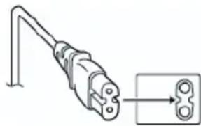
of the power cord into the AC Adapter until it is no longer wobbly, and then plug the larger end of the power cord in to an AC outlet.
FOR EUROPE
WARNING
This is a Class A product. In a domestic environment this product may cause radio interference in which case the user may be required to take adequate measures.
The plastics packaging bags may cause suffocation when they are covered over the head. Tear them open, and keep them away from the reach of infants and children by ensuring that they are disposed of properly.
For Brazil
Consult your dealer as special technique is required when installing this product. Ensure that the fixing screws or nuts are tightened securely, otherwise, the unit may fall off.
Mounting to a firm place
As the unit contains parts rotating at high speed, mount it on a firm place with sufficient strength to support the vibration and weight of the unit.
Mass: Approx. 1.7 kg 400
Approx. 1.5 kg 200N 200
If the strength is weak, the vibration will cause fuzzy images on the monitor screen. In the worst scenario, the camera may even fall off and hit somebody, resulting in serious accidents.
Mount the camera correctly
When mounting the unit to the ceiling, make sure to use a ceiling mounting bracket. Be sure to connect the fall prevention wire (sold separately) and tighten the fixing screws or nuts securely.
Using the correct power and voltage
To supply power to this unit, use a DC 12 V or PoE (IEEE802.3af) power. Make use of the correct voltage. Use the supplied AC adapter for the DC 12 V power supply. Do not use the supplied AC adapter on other devices.
Inspect the unit regularly
Screws may be loosened due to vibration or deterioration of the mounting section. Perform regular inspections for loosened screws and check whether there is any danger of the unit falling off.
Do not hang on this product, shake it, or hang objects over it. Applying an excessive load may cause the product to fall off and result in accidents.
Do not modify this product. It may result in accidents.
Do not place any object inside the product. Placing a metallic or inflammable object may cause a fire or shock hazard.
Contents
Getting Started
Safety Precautions 4
Contents 11
Main Features 13
Precautions 14
Names of Parts 16
Basic System Diagram 20
Installation/Connection
Mounting the Camera to the Ceiling Mount Bracket 21
Attaching Label to the Camera 21
Installing the Camera on the Ceiling 22
Installing the Camera on a Desktop 23
Attaching the Camera to a Tripod 23
Connecting the Cables 23
Network Features 24
Operating Environment 24
Checking the IP address 24
IP address settings 24
Confirming the Connection 25
Firmware Update 26
Using View Remote
View Remote Screen 27
Video 28
Image 29
Audio 29
System 30
Network 30
NDI Config 400 200N 33
Information 33
Shooting
Basic Shooting Procedures 34
Selecting the Video Output Resolution and Frame
Rate 34
Connecting to the Network
Performing Live Streaming 35
Menu Display and Detailed Settings
Menu Screen Hierarchical Chart 38
GUI Settings 39
Exposure 39
Color 41
Image 42
P/T/Z (P/T/Z) 42
Noise Reduction 43
Setup 43
Communication Setup 43
Restore Default 44
Others
Troubleshooting 45
Specifications 46
Software License Agreement 49
Important Notice concerning the Software ..... 50
Symbols used
Caution: Describes precautions concerning the operation of this product.
Memo: Describes reference information, such as functions and usage restrictions of this product.
400
: Feature available on KY-PZ400NWU/KY-PZ400NWE/KY-PZ400NBU/KY-PZ400NBE only.
200N
: Feature available on KY-PZ200NWU/KY-PZ200NWE/KY-PZ200NBU/KY-PZ200NBE only.
200
Feature available on KY-PZ200WU/KY-PZ200WE/KY-PZ200BU/KY-PZ200BE only.
Content of this manual
- All rights reserved by JVCKENWOOD Corporation. Unauthorized duplication or reprinting of this manual, in whole or in part, is strictly prohibited.
- Illustrated designs, specifications and other contents of this manual are subject to change for improvement without prior notice.
- The terms HDMI and HDMI High-Definition Multimedia Interface, and the HDMI Logo are trademarks or registered trademarks of HDMI Licensing Administrator, Inc. in the United States and other countries.
- NDI is a trademark or registered trademark of Vizrt Group in the United States and other countries.
- macOS is a trademark of Apple Inc., registered in the U.S. and other countries.
- Google Chrome is a trademark and/or registered trademark of Google LLC.
- QR Code is a registered trademark of Denso Wave Incorporated.
- Microsoft and Windows are registered trademarks of Microsoft Corporation in the United States and other countries.
- Other product and company names included in this instruction manual are trademarks and/or registered trademarks of their respective companies. Marks such as ™ and ® have been omitted in this manual.
Main Features
4K Ultra HD 400
Equipped with a new-generation premium-quality 1/2.5" UHD CMOS sensor with a maximum number of 8.51 megapixels, the camera supports 4K (3840 x 2160) ultra-high resolution images. It also offers downward compatibility with other resolutions including 1080p and 720p.
Equipped with a 1/2.8" CMOS sensor (2.07 megapixels) that supports HD output 200N 200
This camera is equipped with a 1/2.8" CMOS sensor (2.07 megapixels) that enables video depiction of different scenes in HD resolution.
71° wide-angle lens + 12x optical zoom 400
The camera comes with an originally-customized premium 4K ultrawide-angle lens that boasts more than 8 megapixels, a 12x optical zoom and a maximum horizontal viewing angle of 71°.
Comes with a 20x optical zoom lens 200N 200
This camera comes with a 20x high-magnification optical zoom lens that captures a large view of the subject from a far distance.
Supports UVC (USB Video Class) and usable as a web camera 200N 200
This camera can be used as a web camera by connecting it to a PC directly using a USB cable (sold separately). You can enjoy high-quality and high-magnification images during web conferences or remote meetings.
Supports the NDI|HX streaming protocol 400 200N
This camera supports the NDI|HX protocol that enables high efficiency, low bandwidth IP transmission, making it possible to connect it with NDI-compatible devices.
Supports the SRT streaming protocol
This camera supports the SRT streaming protocol to help reduce packet loss and network latency and improve the communication quality, thereby enabling stable video distribution.
Streaming in VITC that is synchronized with NTP
This camera supports the VITC (Vertical Interval Time Code) as a format for superimposing time information of the NTP (Network Time Protocol) on the video stream, and enables synchronization with multiple cameras through the network.
H.264/H.265/Motion JPEG encoding and dual streaming
This camera supports “H.265”, which has a lower bitrate than “H.264” while delivering the same level of picture quality. “Motion JPEG” offers compression in high picture quality with low latency and minimal deterioration in picture quality. It also supports dual streaming, which allows the use of two streams (First Stream and Second Stream) separately.
Low power sleep feature
The camera offers a low-power sleep/wake-up feature that consumes less than 400mW in sleep mode.
Ultra-low light shooting
Applying the 3D noise reduction algorithm helps to significantly reduce image noise. It allows images to remain clean and clear under ultra-low light conditions.
Multiple interfaces
The camera is equipped with an HDMI and a 3G-SDI terminal.
These terminals support simultaneous HDMI and LAN output or simultaneous 3G-SDI and LAN output.
Remote Control Unit
The RS-232 and RS-485 serial ports can be used to control the camera remotely.
Built-in gravity sensor
The camera has a built-in gravity sensor to automatically detect whether it is suspended from the ceiling.
Intelligent exposure
This feature allows effective exposure compensation according to the photographer's intentions.
Dual power supply
The camera supports dual power supply (PoE and DC IN 12V).
Precautions
Installation Location
■ Be sure to install the camera horizontally.
Storage and Usage Locations
- Allowable ambient temperature and humidity: Be sure to use this unit within the allowable temperature range of 0 °C to 40 °C (32 °F to 104 °F) and a relative humidity of 30 % to 80 %. Using this unit at a temperature or humidity outside the allowable ranges could result not only in malfunction but also serious impact on the CMOS elements, as small white spots may be generated. Please exercise care during use. ■ Strong electromagnetic waves or magnetism: Noise may appear in the picture or audio and/or the colors may be incorrect if this unit is used near a radio or television transmitting antenna, in places where strong magnetic fields are generated by transformers, motors, etc., or near devices emitting radio waves, such as transceivers or cellular phones. ■ Use of wireless microphone near this unit: When a wireless microphone or wireless microphone tuner is used near this unit during recording, the tuner could pick up noise. ■ Inadequate heat ventilation may result in malfunction of this product. Be sure not to block vents around the product. This product discharges heat from the surface of the main unit.
- Do not install it at locations directly subjected to cold air, such as near the vents of air-conditioners, or at locations with high temperature.
- Avoid using or placing this unit in the following places.
- Locations beyond the allowable operating humidity range of 30 %RH to 80 %RH. (Condensation is not allowed)
- Near equipment that emits strong magnetic fields, such as transformers or motors.
- Near equipment that emits radio waves, such as transceivers and mobile phones.
- Locations with excessive dust and sand.
- Locations that are subject to vibration, such as inside a car or ship.
- Locations prone to moisture, such as near windows.
- Locations subject to steam or oil, such as kitchens.
- Special environments, such as those with combustible atmosphere.
- Locations that are subjected to radiation, X-rays, salt attack or corrosive gases.
- Locations where chemicals are used such as swimming pools.
- Hot or cold places that are beyond the allowable ambient operating temperature range.
Transportation
- Do not throw away the original box of the unit. Keep it and use it for transporting the unit in future.
Carrying the Camera
■ Do not drop or hit this unit against a hard object when transporting. ■ Remove the connecting cables when transporting the unit. ■ When transporting the unit, turn off the power of the system. - Pack the unit with cushioning material so as to avoid shock when transporting. ■ Handle the unit with care and do not subject it to vibration or shock.
Power Saving
If the camera is not to be used for a long time, turn off the power of the system for safety and energy conservation reasons.
Maintenance
■ Turn off the power before performing any maintenance. ■ Wipe the external cabinet of the unit with a soft cloth. Do not wipe the body with benzene or thinner. Doing so may cause the surface to melt or turn cloudy. When it is extremely dirty, soak the cloth in a solution of neutral detergent, wipe the body with it, and then use a clean cloth to remove the detergent.
License Notices
MPEG LA AVC THIS PRODUCT IS LICENSED UNDER THE AVC PATENT PORTFOLIO LICENSE FOR THE PERSONAL USE OF A CONSUMER OR OTHER USES IN WHICH IT DOES NOT RECEIVE REMUNERATION TO (i) ENCODE VIDEO IN COMPLIANCE WITH THE AVC STANDARD ("AVC VIDEO") AND/OR (ii) DECODE AVC VIDEO THAT WAS ENCODED BY A CONSUMER ENGAGED IN A PERSONAL ACTIVITY AND/OR WAS OBTAINED FROM A VIDEO PROVIDER LICENSED TO PROVIDE AVC VIDEO. NO LICENSE IS GRANTED OR SHALL BE IMPLIED FOR ANY OTHER USE. ADDITIONAL INFORMATION MAY BE OBTAINED FROM MPEG LA, L.L.C. SEE HTTP://WWW.MPEGLA.COM
Copyright
■ Any recordings made on this camera that are played back for profit or public preview may infringe on the rights of the owner of the recordings. Do not use the recordings for purpose other than personal enjoyment without prior consent from the owner. And even for personal enjoyment, you may not be able to record without permission from the owner.
Login Password
The default password is widely known. It is very dangerous to use the password without changing it. Set a password that is not easily guessed. It is also recommended to change the password regularly.
Others
This camera will perform the initial operation of pan/tilt/zoom upon powering on. ■ The camera body may be captured in the recording depending on the pan, tilt or zoom position. - Do not subject the lens to strong light source such as sun rays. This may cause the equipment to malfunction. During audio input/output, noise may occur when the rotation mechanism is rotated horizontally/vertically, when zooming is performed or when the power is turned on/off. This is not a malfunction. The pan operation range of this product is limited to ±170°. Regardless of the function, operation is not possible beyond this range. ■ Some switching hubs of products that are equipped with intelligent features may include a broadcast/multicast suppression function. Viewing of multicast images on this product may fail if this function is enabled. The dark areas on the screen may appear grainy or white spots may increase. When switching between color and black-and-white images, the brighter area on the screen is emphasized, which may reduce the visibility. However, this is not a malfunction. If the power supply voltage is momentarily cut off or reduced due to lightning or turning on of the air conditioner's power, the image may be disrupted or noise interference may occur.
■ When shooting objects with a luminance difference or near a light source, ghost may occur on the screen. This is a feature of the built-in lens, and is not a malfunction.
■ When the monitor in use has a wide display area, lines may appear at the peripheral area of the screen.
■ Operation via an infrared remote control unit may not work depending on where and how the camera is installed.
■ An afterimage can appear if you view a moving object on the monitor output, however this is not a malfunction.
■ Do not put anything into the camera unit. Metal and flammable items entering from the connectors can result in fire or electric shock.
■ The camera may not show stable pictures for a few seconds immediately after the power is turned on, but this is not a malfunction.
■ Do not drop this unit or subject it to strong impact or vibration as it is a precision equipment.
■ Optical performance of lens Due to the optical performance of the lens, color divergence phenomena (magnification chromatic aberration) may occur at the periphery of the image. This is not a camera malfunction.
■ Noise may appear in the image when switching modes.
■ Use the supplied AC adapter for the power supply (DC 12 V). Do not use the supplied AC adapter on other devices.
■ Use the supplied power cord. And do not use the supplied power cord for any other devices.
- Before starting an important recording, be sure to perform a test recording to confirm that normal recording is possible.
- We shall not be liable for the loss of recordings or opportunities in the event that recording could not be performed due to a problem that arises during the use of the video camera or recorder.
Names of Parts
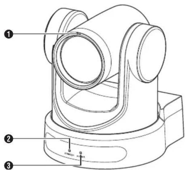
1 Tally lamp 400 Light turns on or off during external control. Turns on/off according to the menu setting and blinks depending on the status of this camera. ② STANDBY lamp Lights up in green during standby. ③ POWER lamp Lights up in blue when the power is turned on.
Terminal Section
① LINE OUT terminal ② LINE IN terminal ③ DC 12V terminal ④ LAN terminal ⑤ USB 2.0 terminal ⑥ USB 3.0 terminal 200N 200
⑦ 3G-SDI terminal
8 HDMI terminal
⑨ RESTORE switch (Reset switch)
Memo: ____
- Press and hold down to activate reset.
⑩ RS232 OUT terminal
11 RS232 IN terminal RS232 communication control The serial port parameters are as follows.
- Half duplex mode
- Baud rate: 2400/4800/9600/38400 bps
- Start position: 1 bit • Data bit length: 8 bits
- Stop bit length: 1 bit
- Check digit: None
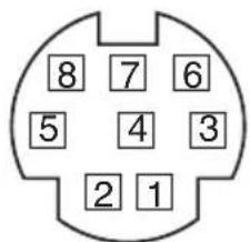
| RS-232C IN RS-232C OUT | |||
| Pin Number | Signal Name | Pin Number | Signal Name |
| 1 DTR_IN | 1 DTR_OUT | ||
| 2 DSR_IN | 2 DSR_OUT | ||
| 3 TXD_IN | 3 TXD_OUT | ||
| 4 GND 4 GND | |||
| 5 RXD_IN | 5 RXD_OUT | ||
| 6 GND 6 GND | |||
| 7 IR_OUT | 7 NC | ||
| 8 NC 8 NC | |||
Corresponding Pins between Camera and Windows DB-9
| Camera | Windows DB-9 |
| 1.DTR | 1.CD |
| 2.DSR | 2.RXD |
| 3.TXD | 3.TXD |
| 4.GND | 4.DTR |
| 5.RXD | 5.GND |
| 6.GND | 6.DSR |
| 7.IR OUT | 7.RTS |
| 8.NC | 8.CTS |
| 9.RI |
Corresponding Pins between Camera and Mini DIN
| Mini DINCamera | |
| 1.DTR | 1.DTR |
| 2.DSR | 2.DSR |
| 3.TXD | 3.TXD |
| 4.GND | 4.GND |
| 5.RXD | 5.RXD |
| 6.GND | 6.GND |
| 7.IR OUT | 7.NC |
| 8.NC | 8.NC |
⑫ RS485 terminal
- Half duplex mode
- Baud rate: 2400/4800/9600/38400 bps
- Start position: 1 bit • Data bit length: 8 bits
- Stop bit length: 1 bit
- Check digit: None
13 SYSTEM SELECT switch
For selecting a video format for the HDMI or 3G-SDI output.
(☑ P34 [Video output using the SYSTEM SELECT switch])
■ When [Video]→[Video Settings]→[Video Format] in the web menu is configured to "Dial Priority"
400
| Terminal Number | Video Format | |
| HDMI 3G-SDI | ||
| 0 192 | 0x1080/60p 1920x | 1080/60p |
| 1 192 | 0x1080/50p 1920x | 1080/50p |
| 2 192 | 0x1080/60i 1920x | 1080/60i |
| 3 192 | 0x1080/50i 1920x | 1080/50i |
| 4 192 | 0x1080/30p 1920x | 1080/30p |
| 5 128 | 0x720/60p 1280x | 720/60p |
| 6 | 1920x1080/29.97p | 1920x1080/29.97p |
| 7 | 1920x1080/59.94i | 1920x1080/59.94i |
| 8 | 1920x1080/59.94p | 1920x1080/59.94p |
| 9 128 | 0x720/59.94p 1280 | 0x720/59.94p |
| A | 3840x2160/29.97p | 1920x1080/29.97p |
| B 192 | 0x1080/60p 1920x | 1080/60p |
| C 384 | 0x2160/25p 1920x | 1080/25p |
| D 384 | 0x2160/30p 1920x | 1080/30p |
| E 192 | 0x1080/25p 1920x | 1080/25p |
| F 128 | 0x720/50p 1280x | 720/50p |
200N 200
| Terminal Number | Video Format | |
| HDMI 3G-SDI | ||
| 0 192 | 0x1080/60p 1920x | 1080/60p |
| 1 192 | 0x1080/50p 1920x | 1080/50p |
| 2 192 | 0x1080/60i 1920x | 1080/60i |
| 3 192 | 0x1080/50i 1920x | 1080/50i |
| 4 192 | 0x1080/30p 1920x | 1080/30p |
| 5 128 | 0x720/60p 1280x | 720/60p |
| 6 | 1920x1080/29.97p | 1920x1080/29.97p |
| 7 | 1920x1080/59.94i | 1920x1080/59.94i |
| 8 | 1920x1080/59.94p | 1920x1080/59.94p |
| 9 128 | 0x720/59.94p 1280 | 0x720/59.94p |
| A 192 | 0x1080/60p 1920x | 1080/60p |
| B 192 | 0x1080/60p 1920x | 1080/60p |
| C 192 | 0x1080/60p 1920x | 1080/60p |
| D 192 | 0x1080/60p 1920x | 1080/60p |
| E 192 | 0x1080/25p 1920x | 1080/25p |
| F 128 | 0x720/50p 1280x | 720/50p |
Infrared Remote Control

1 STANDBY button Switches between the standby and normal modes.
Memo: ____
- Power consumption in the standby mode is approximately half of that in the normal mode.
2 NUMBER button For preset configuration or invoking a preset number.
3 * button To be used together with other buttons.
4 PRESET button Stores the preset position. [PRESET] + NUMBER button (1 to 9): Stores the preset position in the selected NUMBER button.
Memo: ____
- Press the buttons above in sequence.
5 HOME button Restores the orientation of the camera to face the front. Functions as a confirmation button when the menu is displayed.
6 RETURN button Functions as a cancel button when the menu is displayed.
7 ZOOM button SLOW ZOOM: Zooms in [+] or zooms out [-] the camera at a low speed. FAST ZOOM: Zooms in [+] or zooms out [-] the camera at a high speed.
8 L/R SET button Press the button together with the NUMBER button [1] or [2] at the same time to pan the camera toward the left or right. - Pressing the left or right side of the [L / R SET] + [1] (STD) at the same time pans the camera toward the left or right accordingly. - Pressing the left or right side of the [L / R SET] + [2] (REV) at the same time pans the camera toward the right or left accordingly. This setting comes in handy in cases such as when the camera is suspended from the ceiling.
⑨ FOCUS button For adjusting the focus.
- [AUTO]: Auto Focus mode (AF) - [MANUAL]: Manual Focus mode (MF)
- During MF, focus is adjusted using [FAR] (for setting focus on a distant subject) and [NEAR] (for setting focus on a nearby subject).
10 P/T RST button Resets the pan and tilt positions.
11 BACKLIGHT button Press the button to enable backlight compensation. Pressing the button again disables backlight compensation.
Memo :
- This feature is available only when [Exposure] is configured to "Auto".
- Use this feature when there is a light source behind the subject that causes the subject to appear dark in the image.
⑫ MENU button Displays the menu or exits the menu display.
13 PAN/TILT CONTROL button Press the arrow button to pan or tilt the camera. Pressing the [HOME] button restores the orientation of the camera to face the front. Moves the cursor when the menu is displayed.
14 RESET button Erases the preconfigured settings. [RESET] + NUMBER button (0 to 9): Erases the preset position in the selected NUMBER button. [*] + [#] + [RESET]: Erases all the preset positions.
Memo : ____
- Press the buttons above in sequence.
15 IR REMOTE CONTROL button For configuring the number of the camera you want to control using the infrared remote control. [*] + [#] + [F1]: Address 1 [*] + [#] + [F2]: Address 2 [*] + [#] + [F3]: Address 3 [*] + [#] + [F4]: Address 4
Memo :
- Press the buttons above in sequence.
16 # button
To be used together with other buttons.
⑰ CAMERA SELECT button
Press the number of the camera you want to control using the infrared remote control.
Memo :
- The remote control unit makes use of 2 AAA dry-cell batteries. - Make sure to load the battery in the correct +/- orientation.

Caution :
- Do not place the remote control at a location that is subject to high temperature. Otherwise, the remote control may be deformed, thus resulting in malfunction.
- Place the batteries at a location that is out of reach of children. In the event that the battery is swallowed by mistake, consult a doctor immediately.
- Do not throw the batteries into fire or place them at a location that is subject to high temperature. Otherwise, the batteries may explode.
- When replacing the batteries, use ones that are of the same model or type. Using a different type of battery may cause it to explode.
Image freeze feature
Pressing the [F4] button freezes the video image and displays a "freeze" caption at the top left corner of the screen for about 5 seconds. Pressing the [F4] button again unfreezes and restores the video image to the original state. An "unfreeze" caption will appear at the top left corner of the screen for about 5 seconds.
Shortcut settings
[*] + [#] + [1]: Configures the default language of the menu to English. [*] + [#] + [3]: Configures the default language of the menu to Chinese. [*] + [#] + [4]: Displays the current IP address. [*] + [#] + [6]: Resets all menu settings to the default values. [*] + [#] + [8]: Displays the camera version. [*] + [#] + [9]: Flips the video image horizontally or vertically. [*] + [#] + [MANUAL]: Restores the default IP address. Memo: ____ Press the buttons above in sequence.
Basic System Diagram

Quick Start
① Check to ensure that the connections are correct before turning on the power. ② Connect the AC adapter to the DC 12 V terminal. The POWER lamp lights up. ③ Initialization is activated after the camera is powered on. The camera lens moves to both the horizontal and vertical limit positions. Initialization is complete after it has moved back to the front view position.
Memo:
- Operation is possible when the light of the STANDBY lamp has turned off.
- If Preset 1 is preconfigured, the camera will move to the Preset 1 position.
Use as a USB camera 200N 200
This camera can be used as a USB camera by connecting the USB3.0 port to a PC using a USB cable (sold separately).
Memo:
- Streaming from the camera will not take place while it is connected to a PC via USB.
- To start video streaming, disconnect the USB connection with the PC and restart the camera.
Mounting the Camera to the Ceiling Mount Bracket
- Be sure to put on protective glasses to protect your eyes from falling objects when mounting the camera.
- Be sure to place the base of the camera horizontally. The camera will not operate properly if it is slanted.
Memo:
- The ceiling mount bracket is not necessary when the camera is installed on a desktop or attached to a tripod.
- If necessary, make a hole (Φ40 mm) to route the connection cable and fall prevention wire (ceiling) into the ceiling.
Caution:
- The fall prevention wire (for ceiling) is not supplied. Make use of the wire while taking note of its length, strength, pull and material (insulation).
- Attach the fall prevention wire (ceiling) to a place with sufficient strength (ceiling slab, etc.).
- Take note of the length, strength, pull and material (insulation) of the fall prevention wire (for ceiling) and use one with a wire strength of 150 N (15 kg) or more.
- The inner diameter of the ring section of the fall prevention wire (ceiling) mounted on the camera should be above Φ3 mm but below Φ4 mm, the outer diameter should be Φ9 mm and below, and the thickness 2 mm and below.
- The camera does not come with mounting screws for attaching it to the ceiling. Make appropriate use of the M5 expansion screws (x4) according to the thickness of the ceiling.
1 Place the ceiling mounting bracket (ceiling side) against the ceiling and mark the mounting position on the ceiling.
Memo:
- Take note of the front direction of the camera when placing the marks.
2 Drill holes into the ceiling at the marked positions.
Memo:
- Insert a straw or toothpick into the mounting holes to determine the depth and required length of the screws.
3 Place the ceiling mounting bracket (ceiling side) against the ceiling again at the marked position
4 Fasten the mounting bracket using the M5 expansion screws (sold separately)
Memo :
- Check that the screws are tightened securely when mounting is completed.

Attaching Label to the Camera

Before installing the camera to the ceiling, attach the JVC logo label as illustrated in the diagram.
1 Peel off the label backing 2 Turn the label upside down 3 Align the center position of "V" of the JVC logo on the camera with that on the label, followed by attaching the label
Memo :
- If there is dust or dirt on the surface, remove accordingly before attaching the label.
- Make sure that the JVC logo label is not tilted when attaching.
Installing the Camera on the Ceiling
Configure the video format settings using the SYSTEM SELECT switch before installing. You are recommended to update the firmware to the latest version before installing.
( P26 [Firmware Update] )
1 Remove the 4 feet from the bottom surface of the camera

2 Use three M3 screws and one 1/4 inch screw that come with the camera to attach the ceiling mounting bracket (camera side) to the bottom surface of the camera

3 Mount the camera to the ceiling mount bracket (ceiling side)
Attach the hook on the ceiling mounting bracket (camera side) to the hole on the ceiling mounting bracket (ceiling side).
4 Use three M3 screws that come with the camera to attach

Fasten the drop prevention wire (sold separately) together with one of the screws.
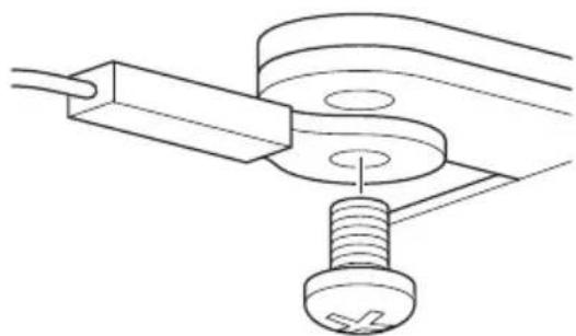
Connect the cables after these procedures.
Installing the Camera on a Desktop
Configure the video format settings using the SYSTEM SELECT switch before installing. You are recommended to update the firmware to the latest version before installing.
(→ P26 [Firmware Update])
- Place the camera on a flat surface.
- Be sure to place the base of the camera horizontally. The camera will not operate properly if it is slanted.
Memo:
- The use of ceiling mount bracket is not required.
Caution:
- Do not move the camera while the power of the system is on. Doing so may result in malfunctions or accidents.
- Do not hold the camera head while carrying the camera.
Connect the cables after these procedures.
Attaching the Camera to a Tripod
Configure the video format settings using the SYSTEM SELECT switch before installing.
- Attach a tripod using the screw hole at the bottom of this product. (1/4-20UNC, ISO1222 (6.35 mm))
- To prevent the camera from falling off, which may result in injuries or damages, read the "INSTRUCTIONS" of the tripod to be used and make sure that it is securely attached.
- To ensure proper pan/tilt operation, set the tripod such that the camera is parallel to the horizontal surface.
Memo :
- The use of ceiling mount bracket is not required.
Caution :
- If the camera exceeds the weight limit of the tripod, do not mount it on the tripod.
- Use the tripod on a stable surface.
- Use screws with a screw length between 4.5 mm and 7 mm.
- Do not install the camera at a high location when the camera is attached to a tripod.
Connect the cables after these procedures.
Connecting the Cables
1 Connect the cables
- Connecting to an HDMI/SDI monitor allows you to check the camera images.
- To input or output the audio, connect the audio cables respectively to the LINE IN/OUT terminals.
2 Connect the LAN cable.
Caution :
- Connect to the LAN cable to devices (routers, hubs, computers, etc.) that are certified under the Telecommunications Business Act.
3 Connect the power cable.
- To supply power from an AC adapter, connect an AC adapter cable.
- To supply power via PoE, do not connect the AC adapter cable.
4 After the power turns on, the POWER lamp lights up and initialization starts
The camera lens moves to both the horizontal and vertical limit positions. Initialization is complete after it has moved back to the front view position.
Memo :
- Operation is possible when the light of the STANDBY lamp has turned off.
- If Preset 1 is preconfigured, the camera will move to the Preset 1 position.
Caution :
- Do not supply power through the AC adapter cable and LAN cable at the same time.
Warning
To supply power to this unit, use a DC 12 V or PoE (IEEE802.3af) power. Make use of the correct voltage.
Supplying a power beyond the rated value may result in failures, smoke or fire. If the camera breaks down, turn off the power and contact our service center immediately.
When a power beyond the rated value is supplied, the internal components may be damaged even if no abnormality is found on the appearance and operation of the camera. Please contact our service center immediately for servicing (charged separately).
Network Features
| Operating Environment
Operation has been verified for the following environments.
- Computer
- OS: Windows 10 Web browser: Google Chrome
- OS: macOS 10.12.6 Web browser: Google Chrome
| Checking the IP address
There are two ways to identify the IP address of the camera.
① Press *, # and the number 4 button on the remote control in sequence to display the IP address of the camera on the screen of the HDMI/SDI monitor connected to the monitor. ② Connect the camera to a PC on the same network and run "upgrade_standard.exe".
Memo :
- Download the "upgrade_standard.exe" from the URL stated on the cover page.
IP address settings
There are two ways to configure the IP address of the camera.
① Log in to the web page, and select [Network] → [Lan Settings] to make changes to the IP address, subnet mask and gateway. Click "Submit" to restart the camera. ② Use "upgrade_standard.exe" to set the IP address.
1 Click the [Search] button
2 Select the IP address of the camera you want to change

3 After changing the value of "IP Address", "NetMask", and "GateWay" is complete, click the [Set] button

- When the setting is successful, the following display appears and the camera restarts.

Confirming the Connection
1 Start up the web browser on the terminal you wish to connect to the camera, and enter the IP address in the address field (Example: http://192.168.0.10)
Memo :
- The default IP address of camera is 192.168.0.10.
2 Enter the user name and password
Enter the user name (jvc) and the password (initial password: 0000) on the login screen to display the Live View screen.
Memo :
- The screen for changing the password is displayed when you log in for the first time. Please change the password.

Firmware Update
Update the firmware of the camera from a Windows PC.
You are recommended to update the firmware to the latest version once it has been released to the public.
Memo:
- Download "upgrade_standard.exe" and the firmware update file from the URL link on the cover page of this manual.
1. Connect the camera to a PC on the same network and run "upgrade_standard.exe" on the PC. 2. Click the [Search] button.
Cameras connected on the same network are displayed.

3. Select the camera to update.

4. Click the [Query] button under the [Upgrade] tab. The current firmware version is displayed. 5. Click the [Type] button and select "MTD".

6. Click the [Open] button and select the update file (.img file). 7. Click the [Upgrade] button.
Update of the firmware starts.
Update is complete when "Upgrade Success" is displayed.
8. After update is complete, press and hold the "RESTORE" switch on the terminal area at the back of the camera.
The camera settings are initialized.
View Remote Screen

Memo:
- Some menu items may not be configurable depending on the operating mode and status of the camera.
① Live
Displays the camera's video image.
Memo:
• Audio is not output. • Supports full-screen display. - To display the menu on the live screen, configure [Encode Codec] of [First stream] or [Second stream] to "H.264". If the menu display is too small, increase the [Resolution] for [First stream] or [Second stream] accordingly.
② Settings menu selection switch Displays the different settings menus.
③ Pan/tilt, menu control and HOME buttons Moves the camera in one of the ◀▶▲▼ directions. Pressing the HOME button restores the pan, tilt and zoom positions to the default setting. If the camera menu is open, move the cursor using ◀▶▲▼, followed by pressing the HOME button to confirm.
Memo:
- Selecting "OSD" at 15 Pan/tilt operation/ Camera menu call-up enables camera menu operation. Selecting "PTZ" enables the camera operation.
④ Zoom In button Moves the zoom toward the Tele-end.
⑤ Zoom Out button Moves the zoom toward the Wide-end.
⑥ Focus In button Moves the focus toward the Tele-end when the camera is in the manual focus mode.
⑦ Focus Out button Moves the focus toward the Wide-end when the camera is in the Manual Focus mode.
8 Horizontal speed control For configuring the speed of horizontal movement. [Setting Values: 1 to ● 10 to 24]
9 Vertical speed control For configuring the speed of vertical movement. [Setting Values: 1 to ● 10 to 20]
⑩ Zoom speed control For specifying the zooming speed. [Setting Values: 1 to ● 5 to 7]
⑪ Focus speed control For setting the focusing speed. [Setting Values: 1 to ● 5 to 7]
⑫ Preset button Saves the current pan/tilt/zoom position to the preconfigured preset number.
⑬ Preset number After configuring the preset number, pressing ⑫ Preset button saves the pan/tilt/zoom position. Pressing ⑭ Preset Call button moves the camera to the saved pan/tilt/zoom position. [Setting Values: 1 to 255]
14 Preset Call button Calls up the corresponding pan/tilt/zoom position using a preset number.
Memo :
- The camera will not move if a pan/tilt/zoom position is not stored in the selected preset number.
15 Pan/tilt operation/ Camera menu call-up Selecting "OSD" displays the camera menu on the live video of the web browser, streaming video and HDMI (SDI) screen. You can use the buttons in 3 to move the menu cursor and confirm a selection. Selecting "PTZ" closes the camera menu. You can use the buttons in 3 for pan/tilt operation.
16 Back button Returns to the next higher level in the menu during menu operation.
⑰ Focus mode Switches between Auto Focus and Manual Focus.
18 Streaming button Switches streaming to on or off.
19 Language button For configuring the display language on the web screen. [Setting Values: ●English, Français, Deutsch, Italiano, Español, русский, 中文(簡), 日本語]
Video
This is the setting screen for the HDMI/SDI terminal and streaming video. After configuring the different items, press the [Submit] button. The settings will be applied when the camera is next restarted.
Video Settings
→ HDMI/SDI Output
For selecting the video output destination. [Setting Values: ●HDMI, SDI]
→ Video Format
For selecting the video output frame rate. [Setting Values: 50Hz, 60Hz, ●Dial Priority] (■ P34 [Selecting the Video Output Resolution and Frame Rate])
→ Encode Level
For selecting a streaming video encoding level. [Setting Values: ●mainprofile, highprofile]
Memo :
- If [Encode Codec] for [First Stream] or [Second Stream] is configured to "H.265", the setting is fixed at "mainprofile".
First Stream, Second Stream
RTSP and RTMP(S) allow simultaneous streaming of videos in the First Stream and Second Stream settings.
→ Encode Codec
For selecting the streaming video codec. [Setting Values: ●H.264, H.265, MJPEG]
→ Resolution
For selecting the streaming video resolution. [Setting Values (First Stream): 3840x2160 400, ●1920x1080, 1280x720, 1024x576, 720x480, 720x408, 640x480, 640x360] [Setting Values (Second Stream): 720x480, 720x408, 640x480, ●640x360, 480x320, 320x240]
Memo:
- The selectable resolutions vary according to the SYSTEM SELECT switch setting.
→ Bit Rate
For configuring the bitrate of the video stream when [Encode Codec] is configured to "H.264" or "H.265". [Setting Values: 32kbps to 61440kbps]
→ Qfactor
For configuring the Q value when [Encode Codec] is configured to "MJPEG". [Setting Values: 1 to 99]
→ Frame Rate
For configuring the streaming video frame rate.
Memo:
- The selectable frame rates vary according to the SYSTEM SELECT switch setting.
→ I Key Frame Interval
Performs encoding with the I-frame as the starting point.
Lowering the value to shorten the interval helps to maintain a stable picture quality even when there are rapid changes in the video image. However, the picture quality for video images with little change will deteriorate.
[Setting Values: 2 to 60]
Memo:
- The selectable I-frame intervals vary according to the SYSTEM SELECT switch setting.
→ Bit Rate Control
For selecting Constant Bitrate (CBR) or Variable Bitrate (VBR). [Setting Values: ●CBR, VBR]
Image
For adjusting the video quality.
After configuring the different items, press the [Submit] button.
Memo:
- If the camera is restarted without pressing the [Submit] button, the settings will be restored to those before the change. Pressing the [Default] buttons restores the settings to the factory default.
- To display the menu on the camera's video image, configure [Encode Codec] of [First stream] or [Second stream] to "H.264". If the menu display is too small, increase the [Resolution] for [First stream] or [Second stream] accordingly.
Brightness
For adjusting the brightness.
[Setting Values: 0 to 14 (●7)]
Saturation
For adjusting the saturation.
[Setting Values: 0 to 14 (●4)]
Contrast
For adjusting the contrast.
[Setting Values: 0 to 14 (●7)]
Sharpness
For adjusting the sharpness.
[Setting Values: 0 to 11 (●6)]
Hue
For adjusting the hue.
[Setting Values: 0 to 14 (●7)]
Flip
Flips the image vertically.
[Setting Values: on, ●off]
Mirror
Flips the image horizontally.
[Setting Values: on, ●off]
Audio
This is the setting screen for the HDMI terminal, SDI terminal and streaming audio.
After configuring the different items, press the [Submit] button.
The settings will be applied when the camera is next restarted.
Audio Settings
→ Audio Switch
Configuring to "on" enables audio input from the LINE IN terminal.
[Setting Values: ●on, off]
Memo :
- This setting remains valid when the camera is connected to a PC via USB. 200N 200
→ Audio Type
Fixed at AAC.
→ Sample Rate
For configuring the sampling rate.
[Setting Values: 44.1K, ●48K]
→ Bit Rate
For configuring the bitrate.
[Setting Values: ●96K, 128K]
→ Input Type
Fixed at "LINE IN".
→ Input Vol
For configuring the volume of the audio input.
[Setting Values: 1 dB to 59 dB (●20 dB)]
→ ADTS Options
For configuring the ADTS option.
[Setting Values: on, ●off]
System
For restarting the system and management of users.
Initialize
→ Reboot
Restarts the camera. Use this function to apply new video or audio settings.
User
→ UserName
User name for accessing the camera from the web browser.
Fixed at "jvc".
→ Passwd
For configuring the password for accessing the camera from a web browser.
Memo :
- The password cannot be configured to the default password value (0000).
→ Guest
User name when logging in as a guest.
Memo :
- When logged in as a guest, you will only be able to view the live and device information screens.
→ Passwd
For configuring the password when logging in as a guest.
Network
For configuring network-related settings.
After configuring the different items, press the [Submit] button.
For Lan Settings, press the [Submit] button below Lan Settings. For other settings, press the [Submit] button right at the bottom.
The settings will be applied when the camera is next restarted.
Lan Settings
→ IP Configuration Type
For selecting the method for configuring the IP address.
[Setting Values: Dynamic IP Address, ●Fixed IP Address]
→ IP Address
Displays the current IP address.
The IP address of the camera can be configured manually when IP Configuration Type is configured to "Fixed IP Address".
The default value is 192.168.0.10.
→ Subnet Mask
Displays the address of the current subnet mask.
The subnet mask of the camera can be configured manually when IP Configuration Type is configured to "Fixed IP Address".
→ Gateway
Displays the address of the current default gateway.
The default gateway of the camera can be configured manually when IP Configuration Type is configured to "Fixed IP Address".
→ DNS Address
Displays the current DNS address.
The DNS address of the camera can be configured manually when IP Configuration Type is configured to "Fixed IP Address".
→ MAC Address
Displays the MAC address of the camera.
Memo :
- Not changeable.
Port Settings
→ HTTP Port
For configuring the HTTP port.
[Setting Values: ●80 or 1025 to 65535]
→ RTSP Port
For configuring the RTSP port.
[Setting Values: ●554 or 1025 to 65535]
→ TCP Port
For configuring the TCP port.
[Setting Values: 1025 to 65535 (●5678)]
→ UDP Port
For configuring the UDP port.
[Setting Values: 1025 to 65535 (●1259)]
→ Standard Protocol
Displays the Standard Protocol port number.
Memo:
- Not changeable.
RTMP(S) Settings
→ First Stream
For configuring the RTMP(S) First Stream video. Configure the setting to "on", select the checkbox corresponding to the "Video" and "Audio" to be streamed, followed by pressing the Save button. RTMP(S) streaming will start after the camera is restarted.
The default value is "off".
Memo :
- The settings in [Video]-[First Stream] will be applied as the video settings.
→ Second Stream
For configuring the RTMP(S) Second Stream video.
Configure the setting to "on", select the checkbox corresponding to the "Video" and "Audio" to be streamed, followed by pressing the Save button. RTMP(S) streaming will start after the camera is restarted.
The default value is "off".
Memo :
- The settings in [Video]-[Second Stream] will be applied as the video settings.
→ MRL
For configuring the streaming server address for the RTMP(S) First Stream/Second Stream.
[Default Value: rtmp://192.168.100.138/live/stream0]
SRT Settings
→ SRT
Configuring it to "on" and pressing the Save button starts SRT streaming after the camera is restarted.
→ SRT Mode
For configuring the SRT connection mode.
[Setting Values: ●Listener, Caller]
→ SRT Server
For setting the address of the SRT server.
The default value is 192.168.100.1.
Memo :
- SRT Mode is configurable only when the setting is set to "Caller".
→ SRT Port
For configuring the SRT port for use during live streaming.
The default value is "4578".
→ SRT Encryption
For configuring SRT encryption.
[Setting Values: AES-256, AES-192, AES-128,
●None]
→ SRT Password
For configuring the SRT password.
You can enter up to 10 to 15 characters.
→ SRT Bandwidth Overhead
Enter the SRT bandwidth overhead using an integer between 5% and 100%.
The default value is "25%".
→ SRT Latency
Enter the amount of SRT latency using an integer between 20 ms and 8000 ms.
The default value is "500ms".
→ SRT FEC
For configuring the FEC mode.
It enables recovery of data streaming packet loss without retransmission.
[Setting Values: 6x6, 8x8, 10x10, ●Off]
→ SRT StreamId
For setting the registered stream ID of the live distribution destination. It allows direct streaming of multiple cameras on a single device.
* You can enter up to 50 characters.
Memo:
- Input and change are possible only when [SRT Mode] is configured to "Caller".
RTSP Settings
→ RTSP Auth
Configuring to "on", the user name and password are required to receive streaming.
[Setting Values: on, off]
Multicast Settings
→ Multicast
Configuring to "on" enables RTP (Real-time Transport Protocol) multicast streaming.
[Setting Values: on, ●off]
Memo:
- This item is active only when [Encode Codec] is set to "H.264".
→ Address
For entering the IP address for multicast. The default value is "224.1.2.3".
→ Port
For configuring the port number used for multicasting to a value between 1025 and 65533. The default value is "6688".
ZeroConfig
For allowing this camera to be detected automatically by external devices (such as switchers) connected to the same LAN. Connection can be established via one link from the menu of the external device.
Memo :
- The Zero Config function is not equipped with the function to change the settings of the camera.
→ Announcement
For configuring the method of connection from an external device during automatic detection of this camera.
[Setting Values: ●on, off]
→ Hostname Prefix
Part of the host name can be changed. (Up to 8 characters)
NTP Settings
Enables display of time information acquired from the NTP server on the streaming video.
→ NTP time sync
Configuring to "on" enables time information to be acquired from the NTP server.
[Setting Values: ●on, off]
→ Time Zone
For setting the UTC time difference in units of 1 hour.
[Setting Values: UTC-11:00 to UTC+13:00 (●UTC +08:00)]
→ Server address
For setting the address of the NTP server.
→ Time interval(min)
For configuring the interval between time queries to the NTP server to a value between 0 and 99999. [Default Value: 1440]
→ Main time show, Sub time show
Configuring to "on" displays the NTP time information on the streaming video.
[Setting Values: on, ●off]
Memo :
- To display the NTP time information on the live screen, configure [Encode Codec] of [First Stream] or [Second Stream] to "H.264". If the display is too small, increase the [Resolution] for [First Stream] or [Second Stream] accordingly.
→ Position
For configuring the position for displaying the First Stream time or Second Stream time. Configure the display position with the top left corner of the screen as [X0, Y0] and the bottom right corner as [X100, Y100].
NDI Config
400
200N
This is the setting screen for the NDI (Network Device Interface) protocol.
NDI Settings
NDI Local Device Name
For configuring the device name displayed in the NDI application.
Default value: "PZ400" 400, "PZ200" 200N
→ NDI Receive Group
For configuring the group name to be used for the NDI application.
The default value is "public".
NDI Firmware Version
Displays the NDI firmware version.
Information
Information
→ Device ID
For configuring the device name of this unit.
→ Device Type
Displays the device type of this unit.
→ Software Version
Displays the current software version.
→ Webware Version
Displays the current web-based software version.
→ Open Source License
Displays the license for the open source software used by this camera.
Basic Shooting Procedures
Preparations
1 Supply power to the camera via a LAN cable or AC adapter
(P23 [Connecting the Cables])
2 Configure the IP address of the camera
For viewing the IP address of the camera and configuring the IP address.
(→ P24 [Checking the IP address])
(P24 [IP address settings])
3 Check the connection
( P25 [Confirming the Connection] )
Memo :
- You are recommended to operate this camera by connecting it to a PC or a controller. The supplied infrared remote control unit might not work depending on the conditions of installation.
Selecting the Video Output Resolution and Frame Rate
On this unit, the SYSTEM SELECT switch is used to configure the HDMI/SDI output resolution and frame rate and determine the selectable streaming formats.
( P36 [Supported Streaming Formats] )
Video output using the SYSTEM SELECT switch
Configure the SYSTEM SELECT switch according to the HDMI/SDI format to be output.
Memo :
• After changing the SYSTEM SELECT switch setting, restart the camera.
■ When [Video]→[Video Settings]→[Video Format] in the web menu is configured to "Dial Priority"
| HDMI OUTPUT | SDI OUTPUT | Frame Rate | SYSTEM SELECT Switch |
| 3840x2160 400 1920x1080 200N 200 | 1920x1080 60p 0, B | 30p D | |
| 29.97p A | |||
| 25p C | |||
| 1920x1080 | |||
| 59.94p 8 | |||
| 50p 1 | |||
| 30p 4 | |||
| 29.97p 6 | |||
| 25p E | |||
| 60i 2 | |||
| 59.94i 7 | |||
| 50i 3 | |||
| 1280x720 1 | 280x720 60p | 5 | |
| 59.94p 9 | |||
| 50p F |
■ When [Video]→[Video Settings]→[Video Format] in the web menu is configured to "60Hz"
| HDMI OUTPUT | SDI OUTPUT | Frame Rate | SYSTEM SELECT Switch |
| 3840x2160 400 1920x1080 200N 200 | 1920x1080 60p 0, 1, 4, 6, | 30p A, C, D | |
| 1920x1080 | 8, B, E | ||
| 60i | 2, 3, 7 | ||
| 1280x720 1 | 280x720 60p | 5, 9, | F |
■ When [Video]→[Video Settings]→[Video Format] in the web menu is configured to "50Hz"
| HDMI OUTPUT | SDI OUTPUT | Frame Rate | SYSTEM SELECT Switch |
| 3840x21604001920x1080200N 200 | 1920x1080 | 25p A, C, D | |
| 1920x1080 | 50p | 0, 1, 4, 6, 8, B, E | |
| 50i | 2, 3, 7 | ||
| 1280x720 1 | 280x720 50p | 5, 9, | F |
Performing Live Streaming
By combining with the decoder or PC application that supports livestreaming, you can perform audio and video streaming via the network.
Supported Codecs
H.264, H.265, Motion JPEG
Memo :
- When the supported codec is configured to "H.265" and the resolution to "3820x2160", live streaming is possible only for RTSP/RTP.
Supported Formats
[Streaming resolution (First Stream)]
3840x2160 400, 1920x1080, 1280x720, 1024x576, 720x480, 720x408, 640x480, 640x360
[Streaming resolution (Second Stream)]
720x480, 720x408, 640x480, 640x360, 480x320, 320x240
[Frame rate (when streaming resolution is
3840x2160)] 400
30p, 29.97p, 25p
[Frame rate (for streaming resolutions other than 3840x2160)]
60p, 59.94p, 50p, 30p, 29.97p, 25p
[Audio]
AAC, 44.1kHz/48kHz, 96kbps/128kbps
Memo:
- The range of configurable resolutions and bitrates varies according to the codec that has been selected.
- Depending on the type of network adapter used and the connection, images and audio sound during live streaming may be choppy.
Supported Protocols
RTSP/RTP, RTMP/RTMPS, SRT, Multicast, NDI|HX 400 200N
Memo:
- Multicast is active only when the supported codec is configured to "H.264".
| Setting Distribution
1 Configure the SYSTEM SELECT switch
Change the SYSTEM SELECT switch setting according to the resolution and frame rate to be used for streaming, followed by restarting the camera.
( P36 [Supported Streaming Formats] )
2 Configure the streaming video and audio format
Configure the codec, resolution, frame rate and bitrate settings in [Video] and [Audio] of the View Remote.
3 Set the distribution protocol
Configure the streaming protocol and related items in the [Network] settings of the View Remote.
4 Restart the camera
After configuring the items, press the [Submit] button followed by the [Reboot] button in the [System] menu to restart the camera.
Receive streaming data
Streaming starts automatically after the camera has restarted. Configure the necessary settings for the decoder and PC application to receive streaming data.
■ URL when receiving streaming data using RTSP/RTP - First Stream rtsp:// : /1 - Second Stream rtsp:// : /2 ■ URL when receiving streaming data using SRT srt:// : ? mode= ■ When receiving streaming data using RTMP(S) Enter the server and stream key into the MRL field under the RTMP(S) setting in the [Network] settings of the View Remote, and view the content from the designated video link after restarting the camera. ■ URL when receiving streaming data using Multicast rtp:// : ■ When receiving streaming data using NDI|HX 400 200N
Install the NDI Tools on the PC for viewing. For more information, please refer to the instruction manual of the NDI Tools.
Supported Streaming Formats
Streaming formats that are supported using the SYSTEM SELECT switch setting are as follows.
Configure the SYSTEM SELECT switch according to the format to be used for streaming.
When [Video]→[Video Settings]→[Video Format] in the web menu is configured to "Dial Priority"
| SYSTEM SELECT Switch | Frame Rate (Max.) | Stream | Resolution | |||||||||
| 4003840x2160 | 1920x1080 | 1280x720 | 1024x576 | 720x480 | 720x408 | 640x480 | 640x360*2 | 480x320 | 320x240 | |||
| D | 30p | First | √ | √ | √ | √ | √ | √ | √ | √ | - | - |
| Second | - | - | - | - | √ | √ | √ | *1 | √ | √ | ||
| A | 29.97p *3 | First | √ | √ | √ | √ | √ | √ | √ | √ | - | - |
| Second | - | - | - | - | √ | √ | √ | *1 | √ | √ | ||
| C | 25p | First | √ | √ | √ | √ | √ | √ | √ | √ | - | - |
| Second | - | - | - | - | √ | √ | √ | *1 | √ | √ | ||
| 0, 2, 5, B | 60p | First | - | √ | √ | √ | √ | √ | √ | √ | - | - |
| Second | - | - | - | - | √ | √ | √ | √ | √ | √ | ||
| 7, 8, 9 | 59.94p *4 | First | - | √ | √ | √ | √ | √ | √ | √ | - | - |
| Second | - | - | - | - | √ | √ | √ | √ | √ | √ | ||
| 1, 3, F | 50p | First | - | √ | √ | √ | √ | √ | √ | √ | - | - |
| Second | - | - | - | - | √ | √ | √ | √ | √ | √ | ||
| 4 | 30p | First | - | √ | √ | √ | √ | √ | √ | √ | - | - |
| Second | - | - | - | - | √ | √ | √ | √ | √ | √ | ||
| 6 | 29.97p *3 | First | - | √ | √ | √ | √ | √ | √ | √ | - | - |
| Second | - | - | - | - | √ | √ | √ | √ | √ | √ | ||
| E | 25p | First | - | √ | √ | √ | √ | √ | √ | √ | - | - |
| Second | - | - | - | - | √ | √ | √ | √ | √ | √ | ||
*1 When [Resolution] of [First Stream] is configured to 3840x2160, the [Resolution] for [Second Stream] can only be configured to 640x360. *2 When [Encode Codec] of [Second Stream] is configured to "MJPEG", the [Resolution] for [Second Stream] can only be configured to 640x360. *3 Configuring [Frame Rate] to "30fps" streams videos at 29.97p. *4 Configuring [Frame Rate] to "60fps" streams videos at 59.94p.
■ When [Video]→[Video Settings]→[Video Format] in the web menu is configured to "60Hz"
| SYSTEM SELECT Switch | Frame Rate (Max.) | Stream | Resolution | |||||||||
| 4003840x2160 | 1920x1080 | 1280x720 | 1024x576 | 720x480 | 720x408 | 640x480 | 640x360*2 | 480x320 | 320x240 | |||
| A, C, D | 30p | First | √ | √ | √ | √ | √ | √ | √ | √ | - | - |
| Second | - | - | - | - | √ | √ | √ | *1 | √ | √ | ||
| 0, 1, 2, 3, 4, 5, 6, 7, 8, 9, B, E, F | 60p | First | - | √ | √ | √ | √ | √ | √ | √ | - | - |
| Second | - | - | - | - | √ | √ | √ | √ | √ | √ | ||
*1 When [Resolution] of [First Stream] is configured to 3840x2160, the [Resolution] for [Second Stream] can only be configured to 640x360.
*2 When [Encode Codec] of [Second Stream] is configured to "MJPEG", the [Resolution] for [Second Stream] can only be configured to 640x360.
■ When [Video]→[Video Settings]→[Video Format] in the web menu is configured to "50Hz"
| SYSTEM SELECT Switch | Frame Rate (Max.) | Stream | Resolution | |||||||||
| 4003840x2160 | 1920x1080 | 1280x720 | 1024x576 | 720x480 | 720x408 | 640x480 | 640x360*2 | 480x320 | 320x240 | |||
| A, C, D | 25p | First | √ | √ | √ | √ | √ | √ | √ | √ | - | - |
| Second | - | - | - | - | √ | √ | √ | √*1 | √ | √ | ||
| 0, 1, 2, 3, 4, 5, 6, 7, 8, 9, B, E, F | 50p | First | - | √ | √ | √ | √ | √ | √ | √ | - | - |
| Second | - | - | - | - | √ | √ | √ | √ | √ | √ | ||
*1 When [Resolution] of [First Stream] is configured to 3840x2160, the [Resolution] for [Second Stream] can only be configured to 640x360. *2 When [Encode Codec] of [Second Stream] is configured to "MJPEG", the [Resolution] for [Second Stream] can only be configured to 640x360.
Menu Screen Hierarchical Chart
Menu ..... (P 39)
EXPOSURE ..... (P 39)
Mode (P 39)
- ExpCompMode ...... (P 39)
L ExpComp ...... (P 39)
Backlight (P 39)
Iris (P 40)
- Shutter (P 40)
Gain (P 40)
Bright (P 40)
Gain Limit (P 40)
Anti-Flicker (P 40)
Meter (P 40)
L DRC (P 40)
COLOR ..... (P 41)
WB Mode (P 41)
RG Tuning (P 41)
BG Tuning (P 41)
R Gain (P 41)
B Gain (P 41)
- Saturation ..... (P 41)
Hue (P 41)
IMAGE (P 42)
Luminance (P 42)
Contrast (P 42)
- Sharpness ...... (P 42)
Flip-H (P 42)
Flip-V (P 42)
B&W Mode (P 42)
L Style ..... (P 42)
Memo:
- Some menu items may not be configurable depending on the operating mode and status of the camera.
- Setting value with the ● mark is the factory default.
- P/T/Z (P 42)
- SpeedByZoom (P 42)
- AF-Zone (P 42)
- AF-Sense (P 42)
- L/R Set (P 42)
- Display Info (P 42)
- Image Freeze ..... (P 42)
- Digital Zoom (P 42)
- Call Preset Speed ..... (P 42) I- Pre Zoom Speed ..... (P 42)
- NOISE REDUCTION ..... (P 43)
I- NR3D-Level (P 43)
- SETUP ...... (P 43)
- Language ..... (P 43)
- DVI Mode (P 43)
- SDI-3G Mode (P 43)
- Video Output ...... (P 43)
- Auto Inversion ..... (P 43) L- Tally Mode ..... (P 43)
- COMMUNICATION SETUP ...... (P 43)
- Protocol (P 43)
- V_Address ...... (P 43)
- V_AddrFix (P 43)
- Net Mode ..... (P 43)
- P_D_Address (P 43)
- P_P_Address (P 43) I- Baudrate ..... (P 43)
- Restore Default ...... (P 44)
-Restore? (P44) L- P/T Limit Reset (P 44)
GUI Settings
Menu
Pressing the [MENU] button on the infrared remote control unit displays the main menu on the HDMI/SDI and streaming screens. You can move the cursor using the arrow buttons. Use the [HOME] button to enter the corresponding menu.
![MENU ►Exposure Color Image P/T/Z Noise Reduction Setup Communication Setup Restore Default [Home] Enter [Menu] Exit](/content/2026/06/1366244/images/afc29a5aaf8e8bc4688608d7f671669abc9d4274b82e225a92db55569318b412.jpg)
Memo :
- To display the menu on the video image on the View Remote screen, configure [Encode Codec] of [First Stream] or [Second Stream] to "H.264". If the menu display is too small, increase the [Resolution] for [First Stream] or [Second Stream] accordingly.
Exposure
Mode
For selecting the method for controlling the exposure.
- Auto Gain/Shutter/Iris are adjusted automatically.
- Manual Gain/Shutter/Iris operate according to the menu setting. • SAE Shutter speed is configured according to the setting in the [Shutter] menu, while gain and iris are automatically adjusted. • AAE Iris is configured according to the setting in the [Iris], while gain and shutter speed are automatically adjusted.
- Bright Adjusts the brightness of the RAW data. [Setting Values: ●Auto, Manual, SAE, AAE, Bright]
ExpCompMode
Performs exposure compensation when this is configured to "On".
[Setting Values: ●Off, On]
Memo :
- This item can be configured when [Mode] is set to "Auto".
→ ExpComp
Adjusts the exposure compensation value. [Setting Values: -7 to +7 (●0)]
Memo :
- This item can be configured when [ExpCompMode] is set to "On".
Backlight
For configuring backlight compensation. [Setting Values: ●Off, On]
Memo:
- This item can be configured when [Mode] is set to "Auto".
Iris
For configuring the iris value (F number).
[Setting Values: ●F1.8, F2.0, F2.4, F2.8, F3.4, F4.0, F4.8, F5.6, F6.8, F8.0, F9.6, F11.0, Close]
Memo:
- This item can be configured when [Mode] is configured to "Manual" or "AAE".
Shutter
For configuring the shutter speed.
- For "60Hz" [Video Format] [Setting values: 1/30, 1/60, 1/90, 1/100, ●1/125, 1/180, 1/250, 1/350, 1/500, 1/725, 1/1000, 1/1500, 1/2000, 1/3000, 1/4000, 1/6000, 1/10000]
- For "50Hz" [Video Format] [Setting values: 1/25, 1/50, 1/75, 1/100, ●1/120, 1/150, 1/250, 1/350, 1/500, 1/725, 1/1000, 1/1500, 1/2000, 1/3000, 1/4000, 1/6000, 1/10000]
Memo:
- This item can be configured when [Mode] is configured to "Manual" or "SAE".
- “1/30” can be selected when frame rate is configured to 30p/29.97p, and “1/25” can be selected when frame rate is configured to 25p. (P34 [Selecting the Video Output Resolution and Frame Rate])
Gain
This function electrically boosts the light sensitivity when there is insufficient illumination on the object. You can set the gain of the video amplifier according to the brightness of the object.
[Setting Values: 0 to 15 (●2)]
Memo:
- This item can be configured when [Mode] is set to "Manual".
Bright
Adjusts the brightness.
[Setting Values: 0 to 17 (●7)]
Memo:
- This item can be configured when [Mode] is set to "Bright".
Gain Limit
For configuring the maximum value for automatically switching the gain level according to the brightness.
[Setting Values: 1 to 15 (●9)]
Memo:
- This item can be configured when [Mode] is configured to "Auto", "SAE", "AAE" or "Bright".
Anti-Flicker
For correcting video image flicker that occurs under a fluorescent light.
400
- For "60Hz" [Video Format] [Setting Values: 50Hz, ●60Hz, Off]
- For "50Hz" [Video Format] [Setting Values: ●50Hz, 60Hz, Off]
200N 200
[Setting Values: 50Hz, 60Hz, ●Off]
Memo:
- This item can be configured when [Exposure] is configured to "Auto", "AAE" or "Bright".
Meter
Shutter speed, iris (F number) and ISO speed are controlled to adjust the exposure to an appropriate level according to the brightness of the subject in the [Mode] settings. Use this setting to configure the method of compensation in this case.
[Setting Values: ●Average, Center, Smart, Top]
Memo:
- This item can be configured when [Mode] is configured to "Auto", "SAE", "AAE" or "Bright".
DRC
Adjusts the intensity of DRC.
[Setting Values: 0 to 8 (●0)]
Color
WB Mode
For setting the white balance mode.
- Auto: Automatically adjusts the white balance according to the color temperature of the lighting for illuminating the subject.
- Indoor: For configuring to a color temperature that is suitable for indoor shooting.
- Outdoor: For configuring to a color temperature that is suitable for outdoor shooting.
- OnePush: When “OnePush” is selected, pressing the [HOME] button adjusts the white balance according to the color temperature of the lighting that is currently used to illuminate the subject.
- Manual: Enables adjustment of the color temperature using R gain and B gain. [Setting Values: ●Auto, Indoor, Outdoor, OnePush, Manual]
RG Tuning
Fine-tunes the R (red) component.
[Setting Values: -10 to +10 (●0)]
Memo:
- This item can be configured when [WB Mode] is set to "Auto".
BG Tuning
Fine-tunes the B (blue) component.
[Setting Values: -10 to +10 (●0)]
Memo :
- This item can be configured when [WB Mode] is set to "Auto".
R Gain
Adjusts the R (red) gain in the Manual mode.
[Setting Values: 0 to 255 (●213)]
Memo :
- This item can be configured when [WB Mode] is set to "Manual".
B Gain
Adjusts the B (blue) gain in the Manual mode.
[Setting Values: 0 to 255 (●177)]
Memo :
- This item can be configured when [WB Mode] is set to "Manual".
Saturation
Adjusts the color density.
[Setting Values: 60% to 200% (●90%)]
Hue
For setting the color phase.
[Setting Values: 0 to 14 (●7)]
Image
Luminance
For adjusting the brightness.
[Setting Values: 0 to 14 (●7)]
* When [Style] is set to a value other than "Bright"
[Setting Values: 0 to 14 (●8)]
* When [Style] is set to "Bright"
Contrast
For adjusting the contrast.
[Setting Values: 0 to 14 (●7)]
* When the [Style] item is configured to "Default" or "Norm"
[Setting Values: 0 to 14 (●9)]
* When the [Style] item is configured to "Bright" or "PC"
Sharpness
Adjusts the outline correction value.
[Setting Values: 0 to 11 (●6)]
* When the [Style] item is configured to "Default" or "Norm"
[Setting Values: 0 to 11 (●7)]
* When the [Style] item is configured to "Bright" or "PC"
Flip-H
Flips the video image in the horizontal direction.
[Setting Values: ●Off, On]
Flip-V
Flips the video image in the vertical direction.
[Setting Values: ●Off, On]
B&W Mode
Switches the video to a grayscale display.
[Setting Values: ●Off, On]
Style
For configuring the picture quality adjustment mode.
[Setting Values: ●Default, STD, Bright, PC]
Memo :
- The settings will not be reset even when you press the RESTORE switch.
P/T/Z (P/T/Z)
SpeedByZoom
Configuring to "On" reduces the speed of pan/tilt movement further as the camera zooms toward the Tele-end.
[Setting Values: ●On, Off]
AF-Zone
For configuring the auto focus reference area.
[Setting Values: ●Center, Bottom, Front, Top]
AF-Sense
Adjusts the auto focus sensitivity level.
[Setting Values: ●High, Low, STD]
L/R Set
Inverts the pan operation.
STD : Use the Right cursor button to move to the right, and the Left button to move to the left
REV : Use the Right cursor button to move to the left, and the Left button to move to the right
[Setting Values: ●STD, REV]
Display Info
Configuring to "On" shows a "Registration is complete" OSD when you have registered a preset position.
[Setting Values: ●On, Off]
Image Freeze
Setting to "On" displays the video image before movement starts as a still image during the interval after preset starts until the camera has reached the registered position.
[Setting Values: ●Off, On]
Digital Zoom
For configuring the digital zoom factor.
[Setting Values: ●Off, 2x, 4x, 8x, 16x]
Call Preset Speed
For configuring the preset pan/tilt speed.
[Setting Values: 1 to 24 (●20)]
Pre Zoom Speed
For configuring the preset zoom speed.
[Setting Values: 0 to 7 (●5)]
Noise Reduction
NR3D-Level
For configuring 3D noise reduction.
[Setting Values: Auto, Off, 1 to 11 (●6)]
Setup
Language
Switches between languages in the menu screen.
[Setting Values: ●English, Français, Deutsch,
Italiano, Español, русский, 中文, 日本語]
DVI Mode
For configuring the audio output from the HDMI terminal.
HDMI : Outputs the audio.
DVI : Mutes the audio.
[Setting Values: ●HDMI, DVI]
Memo :
- Press the [HOME] button to confirm the selection and restart the camera.
SDI-3G Mode
For setting the 3G-SDI mapping structure.
[Setting Values: ●LEVEL-A, LEVEL-B]
Video Output
For setting the terminal to output the video.
[Setting Values: ●HDMI, SDI]
Memo:
- Press the [HOME] button to confirm the selection and restart the camera.
Auto Inversion
For configuring the auto flip setting of the video output.
On: Flips the video image when the camera is mounted to the ceiling. Video is not flipped when the camera is installed on a desktop.
Off: Does not flip the video image when the camera is mounted to the ceiling.
[Setting Values: ●On, Off]
Tally Mode 400
For configuring whether to light up the tally lamp at the front of the camera.
[Setting Values: ●On, Off]
Communication Setup
Protocol
For configuring the control protocols.
[Setting Values: ●Standard, PELCO-D, PELCO-P, Auto]
V_Address
For configuring the address of the Standard protocol.
[Setting Values: 1 to 7 (●1)]
Memo :
- This item can be configured when [Protocol] is configured to "Standard" or "Auto".
V_AddrFix
For configuring the necessity of the Address Set command.
On : Address Set command is not needed.
Off : Address Set command is needed.
[Setting Values: ●Off, On]
Memo :
- This item can be configured when [Protocol] is configured to "Standard" or "Auto".
Net Mode
For configuring the serial port network control.
[Setting Values: ●Serial, Parallel]
Memo :
- This item can be configured when [Protocol] is set to "Standard" or "Auto".
P_D_Address
For configuring the address of PELCO-D.
[Setting Values: 0 to 254 (●1)]
Memo:
- This item can be configured when [Protocol] is set to "PELCO-D" or "Auto".
P_P_Address
For configuring the address of PELCO-P.
[Setting Values: 0 to 31 (●0)]
Memo:
- This item can be configured when [Protocol] is set to "PELCO-P" or "Auto".
Baudrate
For configuring the baud rate of the serial port.
[Setting Values: 2400, 4800, ●9600, 38400]
Restore Default
Restore?
Resets all the menu item settings except for the language setting.
[Setting Values: No, Yes]
Memo:
- Press the [HOME] button to confirm the selection. Preset values will also be initialized. IP address, web password and View Remote settings will not be initialized.
P/T Limit Reset
Resets only the menu settings.
[Setting Values: No, Yes]
Memo:
- Press the [HOME] button to confirm the selection.
Troubleshooting
| Problem Action | |
| Video image does not appear on the monitor | Check to ensure that the power supply of the camera is properly connected, the power voltage is normal and the POWER lamp is on at all times.Restart the camera and check whether the camera has been initialized.Check the video format setting and whether the monitor cable is properly connected. |
| Sometimes the video image is not displayed | Check the video format setting and whether the monitor cable is properly connected. |
| Video image becomes blurry when zoomed to the Tele end | Check whether the camera is installed at a stable location.Check to ensure that there are no vibrating machines or objects near the camera. |
| Video image does not appear on the Web browser | You can use the VLC media player to receive video and audio streams.Access the VLC website. (http://www.videolan.org/vlc)Download and install the VLC media player. |
| Unable to access camera from the Web browser | 1Access the network using a PC to test whether network access is functioning properly.2Disconnect from the network, connect the camera and the PC separately, and reset the IP address of the PC.3Check the IP address, subnet mask and gateway settings of the camera.4Check to ensure that there is no conflict in the MAC address.5Check whether the HTTP port is occupied by a different device. |
| I forgot the IP address or login password | Manage the password properly to avoid forgetting it. If you forgot the password, reset the camera to return to its default settings. (Default IP address: 192.168.0.10; default user name: jvc; default password: 0000) |
| Unable to control using the remote control unit | Replace the batteries in the remote control with new ones and check again.Check whether the camera is in the correct operation mode.Check whether the camera number configured using the remote control unit matches the number of the camera. |
| Unable to control via the serial port | Check to ensure that the protocol and address of the camera are consistent.Check whether the cables are properly connected. |
| Video and audio distortion during streaming | If the [Encode Codec] is configured to “H.264” or “H.265”, changing the [Bit Rate] may improve the condition.If [Encode Codec] is configured to “MJPEG”, changing the [Qfactor] may improve the condition. |
Specifications
General
| Item Description | |
| Power DC 12 V (when an AC adapter is used) PoE | |
| Current consumption | 400: 0.62 A (*1), 0.18 A (*2)200N 200: 0.65 A (*1), 0.19 A (*2) |
| Mass | 400: Approx. 1.7 kg200N 200: Approx. 1.5 kg |
| Allowable operating temperature | 0 °C to 40 °C (32 °F to 104 °F) |
| Allowable operating humidity | 30 %RH to 80 %RH (No condensation) |
| Allowable storage temperature | -20 °C to 50 °C (-4 °F to 122 °F) |
| Dimensions (W × H × D) (*3) | 400: 141.5 mm x 164.5 mm x 168.4 mm200N 200: 141.5 mm x 164 mm x 168.4 mm |
| MTBF > 30000 h | |
*1 Operated in the factory default settings when an AC adapter is in use. *2 Operated in the factory default settings when using power supply from a PoE via a LAN cable. *3 When the tilt position is horizontal.
Terminal Section
| Item Description | |
| [LINE IN] terminal | Φ3.5 mmLine input |
| [LINE OUT] terminal | Φ3.5 mmline output |
| [RS485] terminal | 2-pin Phoenix portProtocols: Standard/Pelco-D/Pelco-P |
| [RS232 IN] terminal | 8-pin mini DINProtocols: Standard/Pelco-D/Pelco-P |
| [RS232 OUT] terminal | 8-pin mini DINProtocol: Use only Standard network |
| [LAN] terminal RJ-45PoE power supply: DC 37 V to 57 VEthernet: 10BASE-T/100BASE-TX/1000BASE-T | |
| Item Description | |
| [3G-SDI] terminal | BNC type720p/1080i/1080p: embedded audio3G-SDI: SMPTE ST424-compliantHD-SDI: SMPTE ST292-compliant |
| [HDMI] output terminal | Type A |
| [USB 2.0] terminal | USB-A type |
| [USB 3.0] terminal 200N 200 | USB-B type |
| [DC 12V] terminal | For use with the supplied AC adapter |
Lens/Camera
| Item Description | |
| Lens | 400: 12x, f = 4.4 mm to 52.8 mm, F1.8 to F2.6200N 200: 20x, f = 4.42 mm to 88.5 mm, F1.8 to F2.8 |
| Image pickup device | 400: 1/2.5-inch Progressive CMOS, maximum effective pixel: 8.51 Megapixels200N 200: 1/2.8-inch Progressive CMOS, maximum effective pixel: 2.07 Megapixels |
| Digital Zoom 16x | |
| Shutter 1/25 s to | 1/10000 s |
| White balance Auto, Indoor, Outdoor, One-push, Manual | |
| Backlight compensation | Available |
| Digital noise reduction | 3D digital noise reduction |
| H&V flip Available | |
| Image freeze Available | |
| No. of presets 25 | 5 |
| Preset accuracy | 0.1° |
Rotation Mechanism Section
| Item Description | |
| Horizontal viewing angle | 400: 71° to 8.2°200N 200: 60.7° to 3.36° |
| Vertical viewing angle | 400: 42.7° to 4.5°200N 200: 34.1° to 1.89° |
| Horizontal rotation range | ±170° |
| Vertical rotation range | -30° to +90° |
| Horizontal rotation speed | 1.7° to 100°/second |
| Vertical rotation speed | 1.7° to 69.9°/second |
Video
| Item Description | |
| Signal system400 | 3840x2160/30p, 25p, 29.97p1920x1080/60p, 50p, 30p, 25p,59.94p, 29.97p, 60i, 50i, 59.94i1280x720/60p, 50p, 59.94p |
| Signal system200N 200 | 1920x1080/60p, 50p, 30p, 25p,59.94p, 29.97p, 60i, 50i, 59.94i1280x720/60p, 50p, 59.94p |
Network
| Item Description | |
| Video compression | H.264, H.265, Motion JPEG |
| Video stream First Stream | Second Stream |
| First Stream resolution | 3840x2160 400, 1920x1080, 1280x720, 1024x576, 720x480, 720x408, 640x480, 640x360 |
| Second Stream resolution | 720x480, 720x408, 640x480, 640x360, 480x320, 320x240 |
| Video bit rate | 32 kbps to 61140 kbps |
| Bit rate type CBR, VBR | |
| Frame rate 60fps | 59.94fps, 50fps, 30fps, 29.97fps, 25fps |
| Audio compression | AAC |
| Audio bit rate 96 | kbps,128 kbps |
| Protocols | Control: Standard, NDI|HX 400 200NStreaming: RTSP/RTP, RTMP/RTMPS, SRT, Multicast, NDI|HX 400 200N |
Infrared Remote Control
| Item Description | |
| Remote control system | Infrared type |
| Battery AAA dry-cell battery x 2 | |
| Battery life Approx. 1 year (varies with the frequency of use) | |
| Operating distance | 8 m (horizontal distance from the front) |
| Allowable operating temperature | 0 °C to 40 °C (32 °F to 104 °F) |
| Dimensions (W × H × D) | 46 mm × 20.8 mm × 168.1 mm |
| Mass | Approx. 90 g |
Accessories
| Accessories | |
| Warranty Card (U model only) 1 | |
| 保修卡 (E model only / For China) | 1 |
| INSTRUCTIONS (Installation/IP Address Settings) | 1 |
| 使用说明书(安装/IP 地址设置)(E model only / For China) | 1 |
| AC Adapter 1 | |
| Power Cord (U model: 1, E model: 2) | |
| RS232C cable 1 | |
| Remote control unit 1 | |
| Ceiling mount bracket set 1 | |
| Screws (M3) 6 | |
| Screw (1/4") 1 | |
| JVC logo label 2 | |
| Lens cap | 1 |
* The warranty card can be found inside INSTRUCTIONS (Installation/IP Address Settings).
| Dimensional Outline Drawing (Unit: mm)
KY-PZ400N
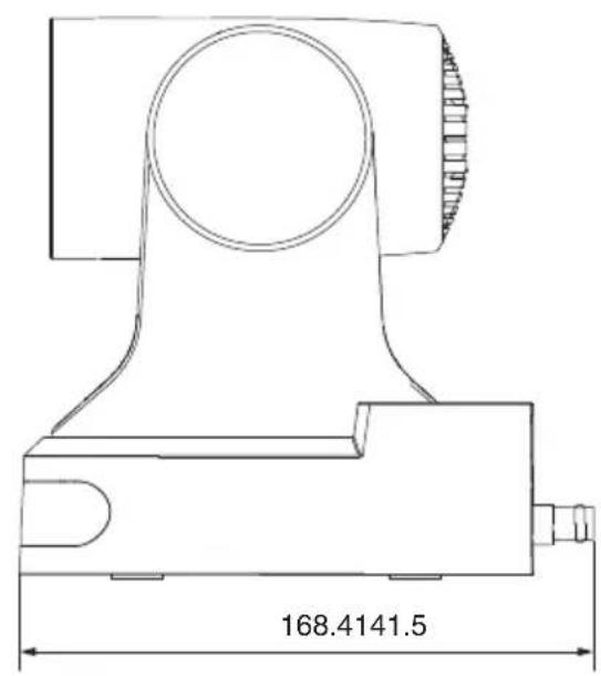
KY-PZ200N/KY-PZ200

* The specifications and appearance of this product are subject to changes for further improvement without prior notice.
Software License Agreement
The software embedded in the Product (hereinafter the “Licensed Software”) provided by JVCKENWOOD Corporation (hereinafter the “Licensor”) is copyrighted to or sublicensable by the Licensor, and this Agreement provides for the terms and conditions which Users shall follow in order to use the Licensed Software. The User shall use the Licensed Software by agreeing with the terms of this Software License Agreement. This Agreement shall be deemed completed at the time the User (hereinafter the “User”) initially used the Product in which the “Licensed Software” is embedded. The Licensed Software may include the software which has been licensed to the Licensor directly or indirectly from any third party. In such case, some third parties require the Users to follow their conditions for use separately from this Software License Agreement. Such software shall not be subject to this Agreement, and the Users are urged to read the “Important Notice concerning the Software” to be provided separately.
Article 1 General Provision
The Licensor shall grant to the User a non-exclusive and non-transferable (other than the exceptional case referred to in Article 3, Paragraph 1) licensed to use the Licensed Software within the country of the User (the country where the User bought the Product (hereinafter the “Country”)).
Article 2 License
- The license granted under this Agreement shall be the right to use the Licensed Software in the Product.
- The User shall not duplicate, copy, modify, add, translate or otherwise alter, or lease the Licensed Software and any related documents, whether in whole or in part.
- The use of the Licensed Software shall be limited to personal purpose, and the Licensed Software shall not be distributed, licensed or sub-licensed whether it is for commercial purpose or not.
- The User shall use the Licensed Software according to the directions described in the operation manual or help file, and is prohibited to use or duplicate any data in a manner violating the Copyright Law or any other laws and regulations by applying whole or a part of the Licensed Software.
Article 3 Conditions for Grant of License
- When the User transfers the Product, it may also transfer the license to use the Licensed Software embedded in the Product (including any related materials, updates and upgrades) on condition that no original, copies or related materials continue in the possession of the User, and that the User shall cause the transferee to comply with this Software License Agreement.
- The User shall not carry out reverse engineering, disassembling, decompiling or any other code analysis works in connection with the Licensed Software.
Article 4 Right pertaining to the Licensed Software
- Any and all copyrights and other rights pertaining to the Licensed Software and related documents shall belong to the Licensor or the original holder of the right who granted to the Licensor the license or sublicense for the Licensed Software (hereinafter the "Original Rightholder"), and the User shall not be entitled to any right other than the license granted hereunder, in respect of the Licensed Software and any related documents.
- The User shall, whenever the User uses the Licensed Software, comply with any laws relating to the copyright and other intellectual property rights.
Article 5 Indemnification of Licensor
- Neither the Licensor nor the Original Rightholder shall be liable for any damage incurred by the User or any third party due to the exercise of the license granted to the User under this Agreement, unless otherwise restricted by law.
- The Licensor will offer no guarantee for the merchantability, convertibility and consistency with certain objective of the Licensed Software.
Article 6 Liability to Third Party
If any dispute has arisen with any third party due to an infringement upon a copyright, patent or any other intellectual property right that was caused by the User's use of the Licensed Software, the User shall settle such dispute at the User's own cost and hold the Licensor and the Original Rightholder harmless from any inconvenience it may cause.
Article 7 Confidentiality
The User shall keep the confidentiality of such portion of the Licensed Software, related documents thereof or any other information to be granted under this Agreement, as well as the conditions of this Agreement as has not yet entered the public domain, and shall not disclose or divulge the same to any third party without approval of the Licensor.
Article 8 Termination
In case the User falls under any of the events described in the following items, the Licensor may immediately terminate this Agreement or claim that the User compensates for the damage incurred by the Licensor due to such event:
(1) when the User violated any provision of this Agreement; or (2) when a petition has been filed against the User for an attachment, provisional attachment, provisional disposition or any other compulsory execution.
Article 9 Destruction of the Licensed Software
If this Agreement is terminated pursuant to the provision of Article 8, the User shall destroy the Licensed Software, any related documents and copies thereof within two (2) weeks from such date of termination.
Article 10 Export Restriction
- The User shall understand that the Licensed Software shall be subject to the export restrictions adopted by the country of User and any other countries.
- The User shall agree that the software will be subject to any and all applicable international and domestic laws including the export control regulation of the country of User and any other countries, and any restrictions concerning the end-users, the use by end-users and importing countries to be provided by the country of User and any other countries, and any other governmental authorities.
- If the User is an agency of the United States of America (the “Government”), the User acknowledge Licensor’s representation that the Licensed Software is a “Commercial Item” as defined in Federal Acquisition Regulation (FAR) part 2.101(g) consisting unpublished “Commercial Computer Software” as those items are used at FAR part 12.212 and is only license the User with the same use right Licensor grants all commercial end users pursuant to the terms of this Agreement.
Article 11 Miscellaneous
- In the event any part of this Agreement is invalidated by operation of law, the residual provisions shall continue in force.
- Matters not stipulated in this Agreement or any ambiguity or question raised in the construction of this Agreement shall be provided or settled upon good-faith consultation between the Licensor and the User.
- The Licensor and the User hereby agree that this Agreement is governed by the laws of Japan, and any dispute arising from, and relating to the rights and obligations under, this Agreement shall be submitted to the exclusive jurisdiction of the Tokyo District Court for its first instance.
Important Notice concerning the Software
Software License Attached to the Product :
The Software embedded in the Product is composed of several independent software components, and in each of such individual components (hereinafter the "Licensed Software"), a copyright of either JVCKENWOOD Corporation (hereinafter "JKC") or a third party subsists.
The Product uses the software component designated in the End-User License Agreement that was executed between JKC and a third party (hereinafter “EULA”).
The Licensed Software covers those corresponding to free software, and, as a condition of distribution of the software component in executable format which is based on the license granted under the GNU General Public License or Lesser General Public License (hereinafter "GPL/LGPL"), it requires an availability of the source code for the relevant component. Please refer to the following URL concerning the distribution of the source code;
https://www3.jvckenwood.com/download/gpl/index.html
Please note that we are unable to answer any inquiry relating to the contents, etc. of the source code. In addition, the Licensed Software includes the software developed or created independently by JKC and there exists an ownership of JKC in such software and any accompanying documents, which is protected by the Copyright Law, any international treaties and other applicable laws. As to matters concerning the handling by JKC of the software components, please refer to the “Software License Agreement” attached hereto. Please note that any software component licensed under “EULA” which is not subject to “GPL/LGPL”, and those developed or created independently by JKC shall not be subject to the requirement for provision of the source code. The software component distributed under “GPL/LGPL” shall be licensed to users without charge, and, therefore, no warranty is given for such software component, either express or implied, within the scope of the applicable laws and regulations. Unless otherwise permitted by applicable laws and regulations or agreed in written form, none of the owners of the copyright or persons entitled to alter or redistribute the software component under the said license shall have any liability for any type of damage or loss resulting from the use of or inability to use such software component. For further details of the conditions of use of such software component or matters required to be complied with, please refer to the relevant “GPL/LGPL”.
Users are urged to read the details for the relevant license carefully before using the software component covered by “GPL/LGPL” and embedded in the Product. Since the terms and conditions of individual licenses are provided by parties other than JKC, the original English version will be displayed by the Product or the Settings screen.
① Access the camera from the Web browser ② Click "Information" on the left side of the screen ③ Press the "Open Source License" button in the "Information" menu screen
4K PTZ REMOTE CAMERA KY-PZ400NWU/KY-PZ400NWE/KY-PZ400NBU/KY-PZ400NBE HD PTZ REMOTE CAMERA KY-PZ200NWU/KY-PZ200NWE/KY-PZ200NBU/KY-PZ200NBE/ KY-PZ200WU/KY-PZ200WE/KY-PZ200BU/KY-PZ200BE
JVC


- DETAILS
- FOR CUSTOMER USE
- PLEASE READ THE FOLLOWING BEFORE GETTING STARTED
- FOR USA
- IMPORTANT SAFETY INSTRUCTIONS
- FOR THE UNITED STATES
- SAFETY PRECAUTIONS
- FOR USA AND CANADA
- CAUTION
- FOR CANADA
- ATTENTION
- WARNING
- WARNING: TO PREVENT FIRE OR SHOCK HAZARD, DO NOT EXPOSE THIS UNIT TO RAIN OR MOISTURE
- NOTES
- WHEN USING THE AC ADAPTER IN AREAS OTHER THAN THE USA
- USING HOUSEHOLD AC PLUG ADAPTER
- IMPORTANT (FOR OWNERS IN THE U.K.) CONNECTION TO THE MAINS SUPPLY IN THE UNITED KINGDOM
- DO NOT CUT OFF THE MAINS PLUG FROM THIS EQUIPMENT
- CAUTIONS
- FOR EUROPE
- FOR BRAZIL
- MOUNTING TO A FIRM PLACE
- MOUNT THE CAMERA CORRECTLY
- USING THE CORRECT POWER AND VOLTAGE
- INSPECT THE UNIT REGULARLY
- CONTENTS
- GETTING STARTED
- INSTALLATION/CONNECTION
- USING VIEW REMOTE
- SHOOTING
- CONNECTING TO THE NETWORK
- MENU DISPLAY AND DETAILED SETTINGS
- OTHERS
- MAIN FEATURES
- K ULTRA HD
- EQUIPPED WITH A 1/2.8" CMOS SENSOR (2.07 MEGAPIXELS) THAT SUPPORTS HD OUTPUT 200N
- ° WIDE-ANGLE LENS + 12X OPTICAL ZOOM
- COMES WITH A 20X OPTICAL ZOOM LENS 200N
- SUPPORTS UVC (USB VIDEO CLASS) AND USABLE AS A WEB CAMERA 200N
- SUPPORTS THE NDI|HX STREAMING PROTOCOL 400 200N
- SUPPORTS THE SRT STREAMING PROTOCOL
- STREAMING IN VITC THAT IS SYNCHRONIZED WITH NTP
- H.264/H.265/MOTION JPEG ENCODING AND DUAL STREAMING
- LOW POWER SLEEP FEATURE
- ULTRA-LOW LIGHT SHOOTING
- MULTIPLE INTERFACES
- REMOTE CONTROL UNIT
- BUILT-IN GRAVITY SENSOR
- INTELLIGENT EXPOSURE
- DUAL POWER SUPPLY
- PRECAUTIONS
- INSTALLATION LOCATION
- STORAGE AND USAGE LOCATIONS
- TRANSPORTATION
- CARRYING THE CAMERA
- POWER SAVING
- MAINTENANCE
- LICENSE NOTICES
- COPYRIGHT
- LOGIN PASSWORD
- NAMES OF PARTS
- INFRARED REMOTE CONTROL
- BASIC SYSTEM DIAGRAM
- QUICK START
- USE AS A USB CAMERA 200N
- MOUNTING THE CAMERA TO THE CEILING MOUNT BRACKET
- MEMO
- PLACE THE CEILING MOUNTING BRACKET (CEILING SIDE) AGAINST THE CEILING AND MARK THE MOUNTING POSITION ON THE CEILING
- DRILL HOLES INTO THE CEILING AT THE MARKED POSITIONS
- PLACE THE CEILING MOUNTING BRACKET (CEILING SIDE) AGAINST THE CEILING AGAIN AT THE MARKED POSITION
- FASTEN THE MOUNTING BRACKET USING THE M5 EXPANSION SCREWS (SOLD SEPARATELY)
- ATTACHING LABEL TO THE CAMERA
- INSTALLING THE CAMERA ON THE CEILING
- INSTALLING THE CAMERA ON A DESKTOP
- ATTACHING THE CAMERA TO A TRIPOD
- CONNECTING THE CABLES
- CONNECT THE CABLES
- CONNECT THE LAN CABLE
- CONNECT THE POWER CABLE
- AFTER THE POWER TURNS ON, THE POWER LAMP LIGHTS UP AND INITIALIZATION STARTS
- NETWORK FEATURES
- OPERATING ENVIRONMENT
- CHECKING THE IP ADDRESS
- IP ADDRESS SETTINGS
- CONFIRMING THE CONNECTION
- FIRMWARE UPDATE
- VIEW REMOTE SCREEN
- ① LIVE
- VIDEO
- VIDEO SETTINGS
- → HDMI/SDI OUTPUT
- → VIDEO FORMAT
- → ENCODE LEVEL
- FIRST STREAM, SECOND STREAM
- → ENCODE CODEC
- → RESOLUTION
- → BIT RATE
- → QFACTOR
- → FRAME RATE
- → I KEY FRAME INTERVAL
- → BIT RATE CONTROL
- IMAGE
- BRIGHTNESS
- SATURATION
- CONTRAST
- SHARPNESS
- HUE
- FLIP
- MIRROR
- AUDIO
- AUDIO SETTINGS
- → AUDIO SWITCH
- → AUDIO TYPE
- → SAMPLE RATE
- → INPUT TYPE
- → INPUT VOL
- → ADTS OPTIONS
- SYSTEM
- INITIALIZE
- → REBOOT
- USER
- → USERNAME
- → PASSWD
- → GUEST
- NETWORK
- LAN SETTINGS
- → IP CONFIGURATION TYPE
- → IP ADDRESS
- → SUBNET MASK
- → GATEWAY
- → DNS ADDRESS
- → MAC ADDRESS
- PORT SETTINGS
- → HTTP PORT
- → RTSP PORT
- → TCP PORT
- → UDP PORT
- → STANDARD PROTOCOL
- RTMP(S) SETTINGS
- → FIRST STREAM
- → SECOND STREAM
- → MRL
- SRT SETTINGS
- → SRT
- → SRT MODE
- → SRT SERVER
- → SRT PORT
- → SRT ENCRYPTION
- → SRT PASSWORD
- → SRT BANDWIDTH OVERHEAD
- → SRT LATENCY
- → SRT FEC
- → SRT STREAMID
- RTSP SETTINGS
- → RTSP AUTH
- MULTICAST SETTINGS
- → MULTICAST
- → ADDRESS
- → PORT
- ZEROCONFIG
- → ANNOUNCEMENT
- → HOSTNAME PREFIX
- NTP SETTINGS
- → NTP TIME SYNC
- → TIME ZONE
- → SERVER ADDRESS
- → TIME INTERVAL(MIN)
- → MAIN TIME SHOW, SUB TIME SHOW
- → POSITION
- NDI CONFIG
- NDI SETTINGS
- INFORMATION
- BASIC SHOOTING PROCEDURES
- PREPARATIONS
- SELECTING THE VIDEO OUTPUT RESOLUTION AND FRAME RATE
- VIDEO OUTPUT USING THE SYSTEM SELECT SWITCH
- PERFORMING LIVE STREAMING
- SUPPORTED CODECS
- SUPPORTED FORMATS
- SUPPORTED PROTOCOLS
- SETTING DISTRIBUTION
- RECEIVE STREAMING DATA
- SUPPORTED STREAMING FORMATS
- MENU SCREEN HIERARCHICAL CHART
- GUI SETTINGS
- MENU
- EXPOSURE
- MODE
- EXPCOMPMODE
- → EXPCOMP
- BACKLIGHT
- IRIS
- SHUTTER
- GAIN
- BRIGHT
- GAIN LIMIT
- ANTI-FLICKER
- N
- METER
- DRC
- COLOR
- WB MODE
- RG TUNING
- BG TUNING
- R GAIN
- B GAIN
- LUMINANCE
- FLIP-H
- FLIP-V
- B&W MODE
- STYLE
- P/T/Z (P/T/Z)
- SPEEDBYZOOM
- AF-ZONE
- AF-SENSE
- L/R SET
- DISPLAY INFO
- IMAGE FREEZE
- DIGITAL ZOOM
- CALL PRESET SPEED
- PRE ZOOM SPEED
- NOISE REDUCTION
- NR3D-LEVEL
- SETUP
- LANGUAGE
- DVI MODE
- SDI-3G MODE
- VIDEO OUTPUT
- AUTO INVERSION
- TALLY MODE
- COMMUNICATION SETUP
- PROTOCOL
- V_ADDRESS
- V_ADDRFIX
- NET MODE
- P_D_ADDRESS
- P_P_ADDRESS
- BAUDRATE
- RESTORE DEFAULT
- RESTORE
- P/T LIMIT RESET
- TROUBLESHOOTING
- SPECIFICATIONS
- DIMENSIONAL OUTLINE DRAWING (UNIT: MM)
- SOFTWARE LICENSE AGREEMENT
- ARTICLE 1 GENERAL PROVISION
- ARTICLE 2 LICENSE
- ARTICLE 3 CONDITIONS FOR GRANT OF LICENSE
- ARTICLE 4 RIGHT PERTAINING TO THE LICENSED SOFTWARE
- ARTICLE 5 INDEMNIFICATION OF LICENSOR
- ARTICLE 6 LIABILITY TO THIRD PARTY
- ARTICLE 7 CONFIDENTIALITY
- ARTICLE 8 TERMINATION
- ARTICLE 9 DESTRUCTION OF THE LICENSED SOFTWARE
- ARTICLE 10 EXPORT RESTRICTION
- ARTICLE 11 MISCELLANEOUS
- IMPORTANT NOTICE CONCERNING THE SOFTWARE
- SOFTWARE LICENSE ATTACHED TO THE PRODUCT
- JVC
Brand : JVC
Model : KY-PZ400
Category : Surveillance Camera