
Nuendo SyncStation - Audio recorder STEINBERG - Free user manual and instructions
Find the device manual for free Nuendo SyncStation STEINBERG in PDF.

| Product type | Hardware synchronizer for digital audio workstations |
| Brand | Steinberg |
| Model | Nuendo SyncStation |
| Category | Audio recorder / Synchronizer |
| Dimensions (W x H x D) | 48.3 x 4.4 x 17.5 cm (19" rack) |
| Weight | 1.4 kg |
| External power supply | AC input 100-240 V, 50/60 Hz, 0.4 A, 30 VA; DC output 5 V, 2 A |
| Display | Backlit LCD 2 lines x 40 characters |
| Input connections | USB 1.1, Word Clock (BNC), AES (XLR and BNC), SPDIF (coaxial and optical Toslink), LTC (XLR), MIDI (DIN), RS422 (9-pin), Video Sync In/Thru (BNC) |
| Output connections | 4 x Word Clock (BNC), AES (XLR and BNC), SPDIF (coaxial and optical Toslink), MIDI Out, RS422 Out, LTC Out, GPIO (25-pin D-sub) |
| Clock outputs | Word Clock A, B, C, D (up to 192 kHz with factors 1x, 2x, 4x, 256x); AES and SPDIF (1x or 2x) |
| Synchronization protocols | LTC, MTC, VITC, Word Clock, Video black burst (bi-level), Video HD (tri-level), RS422 9-pin |
| Main functions | Master clock generation and distribution, timecode synchronization, machine control (MMC, Sony 9-Pin), GPIO interface, extended System Link for sample-accurate alignment |
| Software compatibility | Nuendo (Steinberg application), compatible with digital audio applications accepting MTC and MMC |
| Included accessories | Power cord, USB cable, documentation, drivers and firmware on DVD |
| Maintenance | Clean the device with a dry, soft cloth; do not use solvents or abrasive products |
| Safety | Use the supplied power supply; do not open the casing; disconnect before cleaning; keep away from moisture |
| General information | Warranty: see certificate at www.steinberg.net/warranty; updates available on Steinberg website |
Frequently Asked Questions - Nuendo SyncStation STEINBERG
User questions about Nuendo SyncStation STEINBERG
0 question about this device. Answer the ones you know or ask your own.
Ask a new question about this device
Download the instructions for your Audio recorder in PDF format for free! Find your manual Nuendo SyncStation - STEINBERG and take your electronic device back in hand. On this page are published all the documents necessary for the use of your device. Nuendo SyncStation by STEINBERG.
USER MANUAL Nuendo SyncStation STEINBERG
Operation Manual by Ashley Shepherd
Revision and Quality Control: Cristina Bachmann, Heiko Bischoff, Marion Broer, Sabine Pfeifer, Heike Schilling
The information in this document is subject to change without notice and does not represent a commitment on the part of Steinberg Media Technologies GmbH. No part of this publication may be copied, reproduced or otherwise transmitted or recorded, for any purpose, without prior written permission by Steinberg Media Technologies GmbH.
All product and company names are ^TM or ^® trademarks of their respective owners. Windows XP is a trademark of Microsoft Corporation. Windows Vista is a registered trademark or trademark of Microsoft Corporation in the United States and/or other countries. The Mac logo is a trademark used under license. Macintosh and Power Macintosh are registered trademarks.
Release Date: August 31, 2009
© Steinberg Media Technologies GmbH, 2009.
All rights reserved.
Table of Contents
6 Introduction
7 About this manual
7 What can the SyncStation do?
7 Clock distributor
7 Machine control
7 Timecode synchronizer
7 SyncStation extended System Link
8 GPIO (General Purpose In/Out)
8 Synchronizing with the SyncStation
8 Synchronization basics
8 Timecode (positional references)
10 Clock sources (speed references)
11 Frame reference (phase)
11 Machine control
13 Connecting the SyncStation
14 The inputs and outputs on the SyncStation rear panel
14 USB connection
15 Frame and clock reference inputs
15 Slave clocks (outputs)
15 Machine control
15 GPIO (General Purpose Input Output)
16 SyncStation Controls
17 Front panel controls
17 Cursor buttons and indicator
17 Status LEDs
17 Reset button
18 The SyncStation display
18 Operation display mode
19 Settings Menu display mode
20 Resetting the SyncStation from Nuendo
20 The SyncStation 9-Pin window in Nuendo
20 The SyncStation Status window in Nuendo
21 Menu Reference
23 Root menu
23 Unit menu
23 Unit 01 - Master & Timecode Source
24 Unit 02 - Frame Reference
25 Unit 03 - Timecode Standard
25 Unit 04 - Reference Frame Rate
25 Unit 05 - System Link
25 Unit 06 - System Link Input
26 Unit 07 - Install Template
26 Unit 08 - Line 2 Display
26Clock menu
26 Clock 01 -Clock Reference
27 Clock 02 - System Clock Rate
27 Clock 03 - Audio Pull/Varispeed 0.1%
28 Clock 04 - Audio Pull/Varispeed 4 %
28Clock05-WordclockA
29 Clock 06 - Wordclock B
29Clock07-WordclockC
29Clock08-WordclockD
29 Clock 09 - AES 1/AES 2 Output
30 Clock 10 - Opto/SPDIF Output
30 Clock 11 - Wordclock Input Rate
31 P2 Out menu
31 P2out 01 - Record Tracks
31 P2out 02 - Position Request
32 P2out 03 - Position From
32 P2 In menu
32 P2in 01 - Device ID
33 P2in 02 - RS422-In Track Arming
33 MIDI menu
33 MIDI 01 - MTC -> MIDI Out
33 MIDI 02 - Full Position -> MIDI Out
34 MIDI 03 - MIDI In Track Arming
34 MIDI 04 - MIDI ID
35 USB menu
35 USB 01 - MTC -> Nuendo
35 USB 02 - Full Position -> Nuendo
35 USB 03 - Nuendo Track Arming
35 USB 04 - Nuendo MIDI ID
36 USB 05 - USB Driver
37 Example Studio Setups
38Composer's home studio
39 Mid-level post-production suite
39 Film dubbing theater
41 Technical Data
42 Specifications
42 GPIO pin assignment
43 FCC information (U.S.A.)
43 CE Declaration of Conformity
44 Handling warranty issues
44 Updating the SyncStation driver
44 Updating the SyncStation firmware
45 Index
1
Introduction
About this manual
In this manual you will find a basic overview of what the Nuendo SyncStation can do. A quick synchronization primer will help define the terms and concepts used in this manual. A detailed explanation of all the possible connections that can be made to the SyncStation will follow. Next, the menu system of the SyncStation will be explored in detail and how these settings can also be made in Nuendo. Some example hookup diagrams will be used to explain some of the possible hardware connections to the SyncStation.
What can the SyncStation do?
The Nuendo SyncStation is a complete hardware synchronizer solution for your Nuendo digital audio workstation. It allows your Nuendo system to be accurately synchronized with other audio and video hardware including:
Video Tape Recorders (VTRs)
- Analog tape machines
- Other Steinberg systems (System Link)
- Other Digital Audio Workstations (DAWs)
- Multi-machine synchronization systems
- Centralized house sync generators (black burst, tri-level)
- GPIO interface for record lights, online indicators, and record footswitches
The Nuendo SyncStation is the central hub by which all of these different tape machines and other systems can communicate with Nuendo in order to maintain perfect (sample-accurate) sync between all devices. In today's ever-changing world of new media, HDTV and the Internet, the needs of a synchronization system have evolved, requiring the adoption of new standards such as tri-level HD video sync, hi-resolution audio clocks (96K, 192K) and various transport protocols (MIDI Machine Control, Sony P2 9-Pin RS422). Steinberg's SyncStation includes all of these standards in a professional, rugged and sophisticated piece of hardware designed to meet your synchronization needs.
Clock distributor
In today's digital music and post-production environments, accurate clock synchronization between audio devices is always necessary. The SyncStation can receive, generate and distribute audio clock signals to four word clock outputs, two AES outputs, and consumer Toslink and SPDIF outputs simultaneously.
Machine control
Using both MIDI Machine Control (MMC) and Sony 9-Pin RS422 protocols, the SyncStation can receive and send machine control commands, allowing Nuendo to control audio and video tape machines and have the SyncStation to be controlled from an external controller.
This allows for easy locating of an entire system to a specific timecode position. Plus, machine control can be used to arm tracks for recording and automating audio layback to VTRs using Nuendo's punch features, for example.
Timecode synchronizer
As a timecode synchronizer, the SyncStation can read and generate timecode via LTC, MTC or RS422 connections, so that other computer workstations, MIDI sequencers and audio and video recorders can follow a master timecode source.
SyncStation extended System Link
The SyncStation uses an extended implementation of the System Link protocol, allowing the SyncStation to correct Nuendo's position relative to the edge of each frame down to the sample.
Since MIDI timecode is used to send position data to Nuendo, it can only be accurate to a few milliseconds (depending on the MIDI interface). The System Link connection is used to send sample-accurate position information back to the SyncStation which then calculates an offset to correctly align Nuendo's transport to the edge of the video frame. This is a unique and extremely accurate method of synchronization exclusively provided by the SyncStation.
GPIO (General Purpose In/Out)
With the GPIO interface, the SyncStation can receive and send various external signals, such as "red light" and "online" indicators including support for a record punch foot-switch. The GPIO pin assignment is listed in the section "GPIO pin assignment" on page 42.
Synchronizing with the SyncStation
Before exploring all of the options in the SyncStation, a basic understanding of the concepts and terms involved in audio and video synchronization is needed. For many, this knowledge may be old news and it is provided here only as a convenient way of defining the terms used in this manual.
Synchronization basics
There are three basic components of audio/visual synchronization: position, speed, and phase. If these parameters are known for a particular device, a second device can have its speed and position "resolved" to the first in order to have the two devices play in perfect sync with one another. The process of "resolving" the one device to the other is performed by the synchronizer, in this case, the Nuendo SyncStation.
The synchronizer analyzes the position of the primary (master) device and moves the secondary device to the same position in time. When playback begins, the synchronizer analyzes the speed of the master device and adjusts the playback speed of the secondary (slave) device to perfectly match the first and then maintain that speed in a highly accurate manner, sample-accurate if possible.
The phase component is the alignment of each frame of timecode to the corresponding sample of audio. Simpler, low-resolution synchronization scenarios often ignore the phase relationship between timecode and word clock. Since the SyncStation handles video sync, timecode and word clock in one device, it can use the extended System Link connection to correct the phase between Nuendo and the video frame reference. This is essential for truly sample-accurate synchronization between audio and video.
Timecode (positional references)
The position of any device in the system is most often described using timecode. Timecode represents time using hours, minutes, seconds, and frames to provide a location for each device. Each frame represents a visual film or video frame.
Film uses another positional standard called feet+ frames, which uses lengths of film in feet plus additional frames to denote its position on the timeline. While Nuendo is capable of displaying feet+frames counters and rulers for both 16mm and 35mm film, it is for internal reference only. The SyncStation does not have the ability to resolve direct film synchronization signals (e.g. tach pulses).
Timecode can be communicated in several ways:
LTC (Longitudinal Timecode) is an analog signal that can be recorded on tape. It should be used for positional information primarily. It can also be used for speed and phase information as a last resort if no other clock source is available.
- VITC (Vertical Interval Timecode) is contained within a composite video signal. It is recorded onto video tape and is physically tied to each video frame.
- MTC (MIDI Timecode) is identical to LTC except that it is transmitted via MIDI connections and is a digital signal. MTC is accurate to 1/4 of a frame.
- Sony P2 (9-Pin, RS422) Machine Control also has a timecode protocol that is mainly used for locating and is not nearly accurate enough for speed and phase. It can be used in certain situations where there is no other alternative.
As a timecode synchronizer, the SyncStation can use either LTC, MTC, 9-Pin timecode or its internal generator as a positional reference and generate outgoing timecode based on that reference. This is called the timecode source. For more information on how to set the timecode source, see "Unit 01 - Master & Timecode Source" on page 23.
Timecode has several standards that are used commonly. The subject of the various timecode formats can be very confusing due to the use and misuse of various shorthand names for specific timecode standards and frame rates. The confusing part of this is that regardless of how many frames of video there are per second of timecode, those frames can be moving at different rates depending on the speed of the video reference.
The timecode format can be divided into two variables: frame count and frame rate.
Frame count (frames per second)
The frame count of timecode defines the standard with which it is labelled. There are four timecode standards. The SyncStation uses four letters to denote these standard (F, P, N, and D).
24fps Film (F)
This frame count is the traditional count for film. It is also used for HD video formats and commonly referred to as "24p". However, with HD video, the actual frame rate or speed of the video sync reference is slower, 23.976 frames per second, so timecode does not reflect the actual real-time on the clock for HD video.
- 25fps PAL (P)
This is the broadcast video standard frame count for European (and other PAL countries) television broadcast.
- 30fps non-drop SMPTE (N)
This is the frame count of NTSC broadcast video. However, the actual frame rate or speed of the video standard runs at 29.97fps. This time-code clock does not run in real-time. It is slightly slower by 0.1% .
- 30fps drop-frame SMPTE (D)
The 30fps drop-frame count is an adaptation that allows a timecode display running at 29.97fps to actually show the real-time of the timeline by "dropping" specific frame numbers in order to "catch the clock up" to real-time.
Confused? Well just remember to keep the timecode standard (or frame count) and frame rate (or speed) separate.
Frame rate (speed)
Regardless of the frame counting system, the actual speed at which frames of video go by in real-time is the true frame rate. There are many frame rates when you include pull-downs and pull-ups.
When transferring material between various video formats, it becomes necessary to change the speed (frame rate) of one timecode standard so that video or film frames can line up in some mathematical relationship to the destination format. That's where all the various pull-ups and pull-downs come from.
These are the standard frame rates used in the SyncStation:
23.9fps
This frame rate is used for film that is being transferred to NTSC video and must be slowed down for a 2-3 pull-down telecine transfer. It is also used for HD video and referred to as "24p".
24fps
This is the true speed of standard film cameras.
24.9fps
This frame rate is commonly used to facilitate transfers between PAL and NTSC video and film sources. It is usually used to correct for some error.
25fps
This is the frame rate of PAL video.
29.97fps
This is the frame rate of NTSC video. The count can be either non-drop or drop-frame.
30fps
This frame rate is not a video standard anymore but has been commonly used in music recording. Many years ago it was the black and white NTSC broadcast standard. It is equal to NTSC video being pulled up to film speed after a 2-3 telecine transfer.
- 59.98fps
While the SyncStation does not directly support this frame rate, it can deal with it by using a multiplier to match the speed (29.97 x 2). This rate is also referred to as "60p". While 60fps could theoretically exist as a frame rate, no current HD video camera records at a full 60fps as a standard rate.
Part of the confusion in timecode stems from the use of "frames per second" in both the timecode standard and the actual frame rate. When used to describe a timecode standard, frames per second defines how many frames of timecode are counted before one second on the counter increments. When describing frame rates, frames per second define how many frames are played back during the span of one second of real-time. For example, NTSC timecode (SMPTE) has a frame count of 30fps. However, NTSC video runs at a rate of 29.97fps. So the NTSC timecode standard known as SMPTE is a 30fps standard that runs at 29.97fps real-time.
Clock sources (speed references)
Once the position is established, the next important factor for synchronization is the speed of playback. Once two devices start playing from the same position, they must run at exactly the same speed in order to remain in sync. With digital audio, the speed is determined by the audio clock rate. With video, the speed is determined by the video sync signal.
For proper synchronization, a master speed reference must be used and all devices in the system must follow that reference. As a clock generator and distributor, the SyncStation can receive a master clock signal and generate outgoing clock signals for multiple audio devices.
Internal generator
The SyncStation can use its internal crystal-locked clock generator as a master clock source for an entire system. This generator may also use an external source as a reference for the clock speed.
Video black burst and tri-level sync
When working with external video devices, it is necessary to reference the video frame rate for speed information. A video black burst generator is used to control the speed of each video device including VTRs, video workstations, and even high-end computer video cards. That same black burst signal can be used as a reference for the SyncStation's clock generator.
A black burst signal can be fed into the Video Sync BNC connector of the SyncStation in order to lock the audio sample rate to the video frame rate. The SyncStation supports two types of video sync signals. Standard definition video (SD PAL or NTSC) uses the traditional bi-level sync signal (simply known as black burst) for frame rates up to 30fps. HD video requires the use of tri-level sync signals in frame rates up to 60fps. The SyncStation supports both bi-level and tri-level video sync for the most compatibility in today's HD video world.
Care must be taken to ensure that the incoming video frame rate matches that of the Nuendo project.
The SyncStation has a video sync "thru" connection to allow the chaining of multiple video devices together with one video sync signal.
Word clock
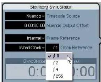
The SyncStation can reference its internal clock to incoming word clock signals received on the "W/C IN" BNC connector. All standard sample rates are supported from 32kHz up to 192kHz .
The word clock input uses a multiplier system to achieve the various sample rates. The internal system clock has three basic rates: 32kHz , 44.1kHz , and 48kHz . Using four multipliers (1x, 2x, 4x, and 256x) , all other standard sample rates can be derived.
For example, to use a 96kHz word clock signal, set the system clock to 48kHz and the reference multiplier to 2x (2× 48 = 96) .
The SyncStation can reference the following clock rates:
- 32kHz (Typically this rate will not use any multipliers since they would be non-standard sample rates.)
- 44.1kHz, 2x = 88.2kHz, 4x = 176.4kHz
- 48kHz, 2x = 96kHz , 4x = 192kHz
- 256x is used only for Digidesign hardware superclock signals.
12.3MHz (48kHz x 256) is not a standard audio sample rate.
This same multiplier system is also used for the SyncStation's word clock and AES (1x and 2x only) outputs.
AES Audio Clock
The SyncStation may also use an AES digital audio signal as a clock reference. Each AES input (XLR and BNC) can be used as a clock reference. The AES inputs also use a multiplier to derive high-resolution sample rates.
SPDIF and Opto
The SPDIF and optical Toslink inputs may be used as a clock reference in the same fashion as the AES inputs.
Video, LTC and MTC (using frame reference)
The SyncStation may use signals other than word clock as clock references. A high-quality video sync signal can be a good source for a clock reference.
In cases where a high-quality audio clock source or video sync signal is not available, other references can be used to derive an audio clock. LTC and MTC sources are not optimal but will suffice if no other clock reference exists. The SyncStation is able to generate audio clock based on these frame references.
For information on selecting a master clock source for the SyncStation, see "Clock 01 - Clock Reference" on page 26.
Frame reference (phase)
The timecode generator in the SyncStation generates timecode referenced to either an internal crystal clock or external frame reference signal. This frame reference is also used to align the audio clock to the edge of the timecode frame.
There are four choices for timecode frame references:
Internal
The SyncStation's internal crystal clock will be used to align each frame of timecode. This is best to use when no additional external video equipment is being used and only video within Nuendo is being played back.
Video
This setting will use the black burst (bi-level SD video) or tri-level (HD video) sync present at the Video Sync In connector to align each frame of timecode. When external video equipment is being synchronized with Nuendo, this is the preferred setting.
LTC
This setting will use the leading edge of an analog timecode signal as a frame reference. This setting is useful when the only positional and speed references both come from analog timecode such asSyncing to an analog audio tape machine.
·MTC
When the only timecode information available is coming in via MIDI, this setting will align each timecode frame to MTC.
For information on how to set the frame reference, see "Unit 02 - Frame Reference" on page 24.
It is imperative that the clock and frame reference be tied together, running at the same speed. If independent frame and clock references are used, they must reference a single clock source for correct operation of the SyncStation.
Machine control
The SyncStation can receive and transmit transport commands and track record arming commands via RS422, MIDI, and USB.
Transport commands
Transport commands from the MIDI and RS422 inputs will be merged and routed to the Master and Timecode Source device as set in "Unit 01 - Master & Timecode Source" on page 23. For example, if the timecode source is set to RS422 Out, all transport commands from the MIDI input and the RS422 In will be routed to the RS422 Out.
Transport commands from the host Nuendo system can be routed independently to the MIDI Out, RS422 Out or the Virtual Master as set in the "Machine Control Output Settings" section of the Project Synchronization Setup dialog. For example, the timecode source could be the LTC reader but transport commands from Nuendo could be routed to the RS422 Out if needed.
Track arming commands
Each machine control input can have its track arming commands routed to a different destination. For example, the MIDI input could have its track arming commands routed to the RS422 output while Nuendo's track arming commands (via USB) could be routed to the MIDI output.
For more information on how to route track arming commands, see "P2in 02 - RS422-In Track Arming" on page 33, "MIDI 03 - MIDI In Track Arming" on page 34, and "USB 03 - Nuendo Track Arming" on page 35.
Virtual Machine Master (VMast)
The SyncStation itself can act like a "virtual tape machine", following transport commands from all machine control inputs and operate its internal timecode generator based on those commands (locate, play, record, stop, etc.).
Once the Virtual Master begins to run, timecode is generated at all outputs (USB, MIDI, RS422, and LTC) so that any connected device will play in sync with the internal timecode generator of the SyncStation.
The SyncStation always regenerates timecode at all its outputs regardless of what the timecode source is. The only difference when using the Virtual Master is that the SyncStation uses its internal generator as the source of the timecode and can respond to transport commands from any machine control input.
9-Pin RS422
The Sony 9-Pin RS422 machine control protocol is a tried and true standard for VTRs. The SyncStation can issue commands to 9-Pin devices (RS422 Out) and also receive 9-Pin commands (RS422 In) from other compatible controllers.
Many large format film mixing consoles have transport controls built in to them for convenience. The console can act as the master controller, issuing commands via 9-Pin to the SyncStation to enter play or stop, for example.
MIDI Machine Control (MMC)
Transport and track arming commands can be sent and received from the MIDI ports of the SyncStation. Third party implementation of the MMC protocol varies with devices. Certain MMC devices might have limited functionality.
Nuendo transport
When the Sync button is engaged on Nuendo's Transport panel, all transport commands are sent to the "Machine Control Output Destination" found in the Project Synchronization Setup dialog.
When this is set to "Steinberg SyncStation", transport commands will go to either the Virtual Master, RS422 Out or MIDI Out. In most cases this should be set to the same output as the timecode source in the SyncStation. Additionally, actions that result in the project cursor being moved in the Project window will cause locate commands to be issued to the SyncStation.
For example, in Edit Mode, the project cursor snaps to the selected event's start point or sync point. This causes a "locate to..." command to be issued to the SyncStation which will route the command to either the RS422 Out, MIDI Out or the internal Virtual Master. That timecode source device will then move to the timecode position causing all connected devices to move to the same position.
Make sure that Nuendo's Machine Control Destination is the same device that generates the timecode so that transport commands result in timecode being generated for the entire system to chase.
If the timecode source is set to LTC, transport commands from the MIDI and RS422 inputs will not be passed on by the SyncStation. In a special case, it is possible to have those transport commands issued to the RS422 Out while using the LTC input for a timecode source. For more information on this special case, see the section "P2out 03 - Position From" on page 32.
2
Connecting the SyncStation
The inputs and outputs on the SyncStation rear panel
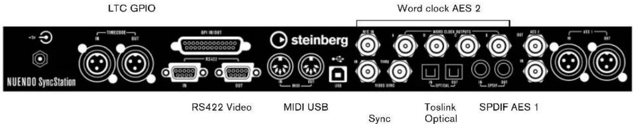
With a basic understanding of the SyncStation functions, connecting the hardware to your system should be straightforward. Once you have planned your system configuration and identified the various clock sources, timecode paths and machine control devices, you can start by connecting the SyncStation to the host Nuendo system.
The SyncStation does not need to be connected to a host Nuendo system in order to operate. With the front panel controls, you can change all pertinent settings and operate the unit stand-alone. However, the extended System Link connection requires the SyncStation to be connected to Nuendo via USB in order to provide sample-accurate sync.
USB connection
The USB port is used to connect the SyncStation to a Nuendo host computer. The USB connection creates two virtual MIDI ports in Nuendo which are used for sending and receiving transport commands and timecode information. The extended System Link connection uses USB to send position correction commands from the SyncStation to Nuendo. It also allows you to display and alter most of the SyncStation settings remotely in Nuendo's Project Synchronization Setup dialog.
For complete information on the configuration of Nuendo's Project Synchronization Setup dialog, refer to the documentation provided with Nuendo.
To connect the SyncStation to a host Nuendo system, proceed as follows:
- On the host computer, make sure that Nuendo is not running.
USB connections can be made while the computer is on but Nuendo will not recognize the device unless it is plugged in before Nuendo launches.
- Connect the power to the SyncStation.
The SyncStation should be on when it is first plugged into the host's USB port.
- Connect the USB cable from the SyncStation to the host computer.
It is advisable that you do not use a USB hub for this connection as it might affect the operation of the SyncStation.
- Install the driver software provided with the SyncStation.
Steinberg's driver software is required for error-free operation of the SyncStation. Make sure you are using the latest driver available by following the directions found in the section "Updating the SyncStation driver" on page 44.
-
Launch Nuendo.
-
On the Devices menu, select the Device Setup option to check if the SyncStation appears.
The SyncStation entry can be found on the Devices list, in the Transport category.
- Click on the SyncStation entry to display the software and hardware version numbers for your unit. If the version numbers appear as all zeros, there was a problem recognizing the unit. After closing Nuendo, try powering down and powering up the SyncStation first to see if the problem persists.
The SyncStation has two USB identification modes: "MIDI Class" and "Steinberg". While the default setting is "Steinberg", it may be necessary to try "MIDI Class" in order for Nuendo to recognize the SyncStation. Refer to "USB 05 - USB Driver" on page 36 for more information.
Frame and clock reference inputs
There are several inputs on the SyncStation that can be used as frame or clock references to the system. Your particular setup will determine which of these connections you will use.
The following inputs are available:
Video Sync In
- Word clock In
AES1In
AES2In
SPDIF In
Optical Toslink In
-MIDI In
- LTCIn
- Sony P2 (9-Pin, RS422) In
Slave clocks (outputs)
Slave devices need to have the same clock reference as the SyncStation. The rear panel offers multiple clock outputs to connect various devices in your system to the SyncStation, ensuring accurate speed between devices.
The following outputs are available:
- Four separate word clock outputs, each with its own multiplier.
AES 1 Out (XLR) - AES 2 Out (BNC)
SPDIFOut
Optical Toslink Out
Each of these connections can function as a clock reference for another digital audio device.

Please note that the SyncStation back panel optical connector can only be used for SPDIF signals (and not for ADAT signals).
Machine control
External machines can be connected to the SyncStation using the MIDI and Sony P2 (9-Pin RS422) connections. The RS422 In should be connected to a master controller device that will control the selected timecode source. The RS422 Out should be connected to any 9-Pin device that you want to control.
GPIO (General Purpose Input Output)
The GPIO interface uses the D sub 25 pin connector on the rear of the SyncStation. The GPIO logic can be utilized to remotely control the SyncStation, connect record and "on air" indicator lights and other custom applications. The pin assignment is provided in the section "Specifications" on page 42. Refer to a qualified engineer or electronics specialist to connect and use the GPIO interface.
SyncStation Controls
Front panel controls
The front panel of the SyncStation contains a two-line display, four cursor buttons, a Cursor indicator light, three status lights and a recessed Reset button.
Cursor buttons Status LEDs
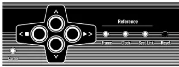
Cursor indicator Reset button
Cursor buttons and indicator
The four cursor buttons are used to switch between the different display options, navigate the various menus and change SyncStation settings.
The Cursor indicator light found just below and to the left of the cursor buttons, informs the user when the Sync-Station is in Settings Menu display mode. When lit, you can use the cursor buttons to navigate the menu system and change settings.
When the Cursor indicator light is unlit, the up and down arrow keys change what is seen on the second line of the display. The left and right arrow keys function as stop and play buttons (respectively) for the selected timecode source.
The left and right arrow keys generate machine control "stop" and "play" commands that are merged with all the other machine control transport commands and sent to the selected timecode source device. This provides a simple way to test a configuration directly from the front panel of the SyncStation.
Status LEDs
The three status LEDs on the right side of the front panel indicate the presence of various signals and the status of the SyncStation in relation to those signals. The indicators are as follows from left to right:
1. Frame reference
The green LED lights up when the chosen frame reference has been detected. It will flash while the SyncStation is in the process of locking to that signal.
2. Clock reference
When the chosen clock reference signal is present, this LED will flash orange while the SyncStation locks its sample clock to the reference and will be solid when the unit has locked.
3. System Link
The blue LED is lit when the extended System Link connection has been made to the SyncStation. When flashing, the Precision Timing option has been turned on but either the System Link signal is not present or is not in sync with the other frame and clock references.
These indicator lights are duplicated in the SyncStation Status window and Project Synchronization Setup dialog in Nuendo.
Reset button
The Reset button resets the USB bus and the LCD screen. This is equivalent to power cycling the unit. Nuendo must be shut down before performing this reset of the SyncStation. Otherwise the program would loose its connection to the SyncStation.
The SyncStation display
The main display has two modes:
- Operation display
- Settings Menu display
You can use the down arrow key to switch between the two display modes:
- Press the down arrow key for more than one second. The cursor LED lights up, indicating that you have entered Settings Menu display mode.
- Repeat this process to return to Operation display mode.
Operation display mode
The Operation display shows current timecode values for Nuendo, SyncStation's Virtual Machine Master, MTC, 9-Pin, and the LTC reader. It also displays the multiplier status of the word clock outputs and the digital audio outputs.
The top line of the display (line 1) displays the selected timecode source device and its status.
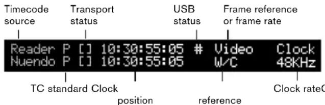
Timecode source
Starting from the left side, the name of the timecode source is displayed first.
Timecode standard
To the right of the timecode source name, a letter represents the current timecode standard being used by the timecode source:
- P = PAL 25fps
- N = NTSC SMPTE 30fps
- D = SMPTE Drop-frame 30fps
- F = Film 24fps
Transport status
To the right of the timecode standard, the transport status for that timecode source is displayed using several icons:
·> = P l a y
·[ ] = S to p
-<<=Rewind
- >> = Fast Forward
Jg = Jog
- Sh = Shuttle
-!> = Not locked to running timecode
Current position
The current position for the timecode source is displayed in the center of the screen.
USB status
Next is shown the USB status, indicated by either a # or *.
-
= USB is connected
- * = Incoming data from the host system
Frame reference or Frame rate
To the right of the USB status one of the following frame references is displayed:
Internal
Video
LTC
MTC
If the clock reference is set to "Use Frame Ref", this part of the display shows the current frame rate of the timecode source.
It is possible that the timecode standard does not match the current frame rate! This may be necessary for some pull up/down operations or to correct for errors in timecode use, but make sure in most conditions that the current frame rate matches the one for the chosen timecode standard.
Clock reference
The clock reference is shown beneath the frame reference/ frame rate on line 2 of the display. When "Use Frame Ref" is selected, the chosen frame reference is displayed. Otherwise, the selected clock reference is shown:
W/C
AES1
AES2
SPDIF
- Opto
System clock rate
At the very right of the display, the system clock rate is shown (32kHz, 44.1kHz, or 48kHz). When set to these standard clock rates, the top line reads "Clock" and the bottom line shows the sample rate.
When using a pull up/down or varispeed setting, the top line reads "Pull" and the bottom line shows the percentage of speed change (+4.17%, -0.1%, etc.) . For more information on how to use pull up/down and varispeed settings, see "Clock 03 - Audio Pull/Varispeed 0.1% on page 27 and "Clock 04 - Audio Pull/Varispeed 4% on page 28.
The range of varispeed is +12.5% to -12.5% .
Line 2 display
Using the up and down arrow keys, the Line 2 display can show the timecode and status for one of the following:
- Blank
Line 2 will display different kinds of status information, e.g. GP In commands.
- Nuendo
This will display the current position, timecode standard and transport status of the connected Nuendo system.
Clock outputs status
When selected, both lines of the LCD are used to display the status of the four word clock outputs plus the AES output, System Link port and the clock rate of the SyncStation.
- Reader (LTC)
The status of the LTC reader.
Virtual Master
The internal timecode generator's status.
MTC
Status of incoming MTC.
RS422
This will display the status of the device connected to the RS422 output. If there is nothing connected, the display will show "!No Machine".
Settings Menu display mode
To alter the SyncStation settings, you must enter the Settings Menu display mode. This is described in the section "The SyncStation display" on page 18.
In Settings Menu display mode all of the SyncStation's settings can be accessed via the front panel controls using the menu system and cursor navigation. When you first enter the Settings Menu display mode, the Root menu is displayed.
The Settings Menu display
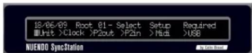
Root menu
The Root menu helps organize settings as they relate to the various parts of the SyncStation. Using the left and right cursor keys, you can navigate to each of the root-level menus. The down arrow key will step through each of the setting menus. The up arrow key will return you to the root level, stepping back through each setting menu.
The six root-level menus are the following:
Unit
C l o c k
P2Out
P2ln
MIDI
USB
Each root-level menu contains settings that relate to the category heading. For more information on the options available in each menu, see the chapter "Menu Reference" on page 21.
Changing Settings
Once you have navigated to the appropriate menu, the left and right arrow keys are used to change settings. In order to make changed settings active, exit the Settings Menu display mode and return to Operation display mode.

When the SyncStation is connected to Nuendo, making changes to settings via the front panel may create conflicts with the settings made within Nuendo.
Resetting the SyncStation from Nuendo
In a situation where you need to reset the SyncStation hardware, you can do so from the SyncStation Settings pop-up window by pressing the Reset Hardware button in the Hardware Unit section. This will reboot all the SyncStation's systems except the USB driver and LCD screen. This reset will maintain the USB connection to Nuendo so restarting the application is not necessary after a reset.
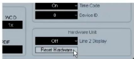
The Reset Hardware button
If for some reason, the USB bus and LCD need to be reset, press the Reset button on the front panel, see "Reset button" on page 17.
The SyncStation 9-Pin window in Nuendo
On the Devices menu in Nuendo, there is a "SyncStation 9-Pin" option. It opens a window that provides direct machine control over the SyncStation and devices connected to its MIDI and RS422 Out ports.
Transport controls in this window are used to remotely control a RS422 device, MIDI Machine Control device or the internal Virtual Master. Pressing the Online button connects the transport controls to the remote device, allowing you to control its transport functions.
The track arming buttons put record tracks on the remote device into record status. Each button will light red when a track is in record.
Auto-Edit
Most VTRs support Auto-Edit mode where the deck will automatically enter record on record-enabled tracks at a given timecode value and stop recording at another timecode value. The record in and out points are defined by the left and right locators in Nuendo.
When sync is engaged in Nuendo's transport panel, recording commands will be routed to the record arming destination device. If that device is a VTR that supports autoedit, the deck will enter record at the left locator and stop recording at the right locator. This facilitates automatic layback of audio to specific timecode values on the VTR.
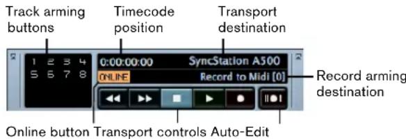
SyncStation 9-Pin window
The SyncStation Status window in Nuendo
The SyncStation Status window in Nuendo is available from the Devices menu. It duplicates the status LEDs of the SyncStation front panel and features a Varispeed indicator and two status lines that display the current state of both the SyncStation and Nuendo. An "H" on the Frame indicator is shown if the SyncStation is receiving an HD video signal. A question mark on any of the indicators means that the corresponding LED on the SyncStation is flashing.
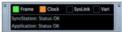
Various messages regarding the status of the SyncStation will be displayed here including precision alignment changes and generator lock status.
Menu Reference
The following table shows the entire menu organization for visual reference:
| Unit Clock P2Out P2In MIDI USB | ||||
| 01-Master & Timecode Source | 01-Clock Reference 01-Record Tracks 01-Device ID 01-MTC -> MIDI Out 01-MTC -> Nuendo | |||
| 02-Frame Reference 02-System Clock Rate | 02-Position Request 02-RS422-In Track Arming | 02-Full Position -> MIDI Out | 02-Full Position -> Nuendo | |
| 03-Timecode Standard | 03-Audio Pull/Vari-speed 0.1% | 03-Position From 03-MIDI In | Track Arming | 03-Nuendo Track Arming |
| 04-Reference Frame Rate | 04-Audio Pull/Vari-speed 4% | 04-MIDI ID 04-Nuendo MIDI ID | ||
| 05-System Link | 05-Wordclock A | 05-USB Driver | ||
| 06-System Link Input | 06-Wordclock B | |||
| 07-Install Template | 07-Wordclock C | |||
| 08-Line 2 Display | 08-Wordclock D | |||
| 09-AESA/AESZ Outputs | ||||
| 10-Opto/SPDIF Output | ||||
| 11-Wordclock Input Rate | ||||
Following this overview of the menu system, each menu and its settings will be reviewed and explained. Most of the SyncStation's settings can also be changed within Nuendo using the available settings window when the SyncStation is selected as the Timecode Source in the Project Synchronization Setup dialog. Following the description of each menu, the equivalent setting within Nuendo will be described.
Root menu
DD/HH/YY Root Select Setup Required
Unit >Clock >P2out >P2in >MIDI >USB
The root-level menu allows you to navigate between the various menus. Since this is for navigation only, there is no equivalent in Nuendo's Project Synchronization Setup dialog.
Note that the date shown at the top left corresponds to the installed firmware version.
Unit menu
The Unit menu deals with the basic SyncStation settings and how timecode is generated in the unit.
Unit 01 - Master & Timecode Source
Unit 01-Master & Timecode Source
Nuendo >RS422-Out >NTC >Umat >LTC
This is perhaps the single most important setting of the SyncStation. This determines the timecode source. In stand-alone mode it also determines where all the transport machine control commands will be routed. (In Nuendo it is possible to set a different machine control destination. See the Operation Manual for details.)
There are five choices for the timecode source:
>Nuendo
When Nuendo is selected as the timecode source, the SyncStation will generate timecode based on the position of the cursor in the Project window and what the current Project Setup settings are regarding the standard and frame rate of Nuendo's timecode. All transport commands will be routed to Nuendo via USB. The Machine Control Input must be set to SyncStation in order for Nuendo to receive these commands.
>RS422-Out
When using the RS422 Out as the timecode source, the SyncStation will lock to timecode that a connected 9-Pin device is being polled for. In order to have Nuendo control this device, the Machine Control Output in the Project Synchronization Setup dialog will have to be sent to the SyncStation's RS422 Out port and "sync" must be enabled in Nuendo.
>MTC
MIDI timecode can be the master timecode source. The SyncStation will lock to MTC received from the MIDI In connector.
>VMast (Virtual Master)
In this mode, the SyncStation's internal timecode generator will be the master timecode source. The SyncStation acts like a virtual device and responds to machine control commands arriving from Nuendo via USB, MMC on the MIDI In connector, or RS422 commands from the 9-Pin input.
> LTC
Analog timecode coming into the SyncStation via the XLR timecode input will be used as the master timecode source.

When LTC is selected as the timecode source, machine control transport commands cannot be routed to any device (in stand-alone mode).
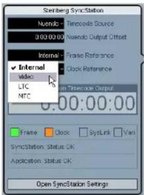
Setting the timecode source in Nuendo
Once the SyncStation has been chosen as the Timecode source within the Project Synchronization Setup dialog, all of the SyncStation settings become available to the left of the Timecode Source section. You can choose a time-code source for the SyncStation from the pop-up menu in the Steinberg SyncStation section.
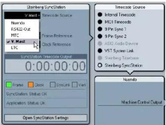
Choosing a timecode source for the SyncStation from the Project Synchronization Setup dialog.
Unit 02 - Frame Reference
Unit 02-Frame Reference
Internal >Video >LTC >MTC
The frame reference for the SyncStation is used to align each frame in the timecode generator and also measure the offset for the extended System Link connection to Nuendo. This is the key to synchronizing with video.
>Internal
When the SyncStation is using the internal crystal-locked clock as a frame reference, the system can operate in a stand-alone fashion, without any external inputs.
>Video
Using a bi-level or tri-level video sync signal as a frame reference is the best way to ensure proper synchronization with other video equipment. This is the primary function of the SyncStation, using a video sync source to generate accurate timecode and sample clock for Nuendo workstations and other digital audio equipment.
> LTC
When necessary, the LTC input can be used as a frame reference. Analog timecode is not a good stable source for a frame reference but in certain situations, it might be the only reference available. If you are trying to synchronize to an analog tape machine that is free running with timecode recorded on a track, using LTC as a frame and clock reference will allow you to lock to it.
>MTC
Due to MTC's inherent timing issues, it should only be used as a frame reference as a last resort.
Changing the frame reference in Nuendo
In Nuendo's Project Synchronization Setup dialog simply choose one of the frame reference options from the pop-up menu.
Choosing a frame reference for the SyncStation.
Unit 03 - Timecode Standard
Unit 03-Timecode Standard >Pal >NonDrop >Film >Drop
The timecode standard determines the frame count that the SyncStation will use. This is not to be confused with the frame rate or speed of the video reference signal.
>Pal (P in SyncStation display)
25 frames per timecode second.
>NonDrop (N in SyncStation display)
30 frames per SMPTE second. NTSC standard. Usually runs at a frame rate of 29.97fps.
>Film (F in SyncStation display)
24 frames per timecode second. Also used for 24p HD video.
>Drop (D in SyncStation display)
Still 30 frames per SMPTE second, but specific frame numbers are skipped in order to bring the timecode clock in line with real-time while the frame rate is 29.97fps NTSC.
The SyncStation recognizes the timecode standard coming from Nuendo, MIDI In, RS422 In, and LTC In. Depending on the standard, either a F, P, N, or D is displayed next to the timecode source name on the LCD. This setting changes the standard for the SyncStation's Virtual Master if it is running stand-alone and not connected to a Nuendo system. If the frame reference is set to Internal and the SyncStation is connected to Nuendo, the Virtual Master will follow Nuendo's Project Setup settings.
Unit 04 - Reference Frame Rate
Unit 04-Reference Frame Rate >25>30>24>24.98>29.97>23.98
The SyncStation automatically recognizes the frame rate coming from Nuendo and will match the setting made in the Project Setup dialog. Any changes made to this setting will only be effective if the SyncStation is not connected to Nuendo and running in stand-alone mode.
Unit 05 - System Link
Unit 05-System Link >Off >On
This setting activates the Precision Time Alignment for sample-accurate sync to the video frame edge.
>Off
The extended System Link is not active. The SyncStation will still provide excellent sync, just not sample-accurate to the frame edge.
>On
When the extended System Link is activated, the Sync-Station will receive sample-accurate timing information from Nuendo and compare that with the frame reference to generate a correction that will precisely align playback to the sample.
Setting up System Link from Nuendo
In the Project Synchronization Setup dialog, click the "Open SyncStation Settings" button to reveal more settings. Select the "Send Data via System Link" option to turn the extended System Link on. Once System Link is turned on, you will see options for setting up outputs from your audio cards and inputs to the SyncStation.
Unit 06 - System Link Input
Unit 06-System Link Input >AES1 >AES2 >Opto >SPDIF
When System Link is active in the SyncStation, one of the four digital audio ports must be selected to receive the signal from Nuendo.
>AES1
The AES 1 input uses the XLR input on the SyncStation. System Link signals will always be sent on the right channel for all audio inputs.
>AES2
This AES input uses the BNC input. BNC connections with coaxial RG59 or higher resolution cable can be run over greater distances than XLR balanced lines. This facilitates remote placement of the SyncStation in the machine room of larger facilities. A transformer adapter may be used to convert XLR AES signals to BNC Coaxial.
>Opto
The Toslink Optical input. This is a stereo AES Toslink input and not an ADAT Lightpipe compatible one.
>SPDIF
The consumer digital audio connection using the RCA input will be used for System Link.
Choosing the SyncStation System Link input in Nuendo
Pop-up menus in the SyncStation Settings pop-up window let you choose the System Link input used on the SyncStation. You must also choose an output from your audio card that will be connected to the SyncStation's digital input by using the Nuendo pop-up menu.
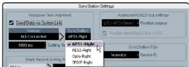
Choosing a digital input for System Link.

The SyncStation always uses the right channel of the selected digital input for System Link.
Unit 07 - Install Template
Unit 07-Install Template >No Change >Factory >Test
This is used to recall the factory settings and for testing purposes. Do not change this setting unless you want to recall the factory settings.
Unit 08 - Line 2 Display
Unit OB-Line 2 Display
Normal >SL >TC >DDR >TCG >USB >Frm >A1 >A2
This setting should be set to Normal as the other options are only used for debugging and testing.
Clock menu
This menu deals with the audio clock and how it is handled in the SyncStation.
Clock 01 - Clock Reference
Clock 01-Clock Reference
Fn >W/C >AES1 >AES2 >Opto >SPDIF
The clock reference is used to generate all the audio clocks coming out of the SyncStation. This is critical to the audio performance of any studio system. The optimal situation is to have a central clock generator that outputs video sync and audio word clock together from a single crystal clock generator. Then you can use the word clock input as the clock reference for the SyncStation, ensuring the best possible audio performance.
There are, however, many situations where the ideal is not possible. Even if only LTC or MTC is available, the Sync-Station can use it as both a frame and clock reference, allowing you to provide the best possible sync in any condition.
>Frm (Use Frame Reference)
This setting uses whatever signal is chosen as the frame reference to derive the audio clock. If a high-quality video sync is used as a frame reference, the derived audio clock can be quite good and provide excellent sync. If only one signal is available to the SyncStation, use this option to utilize that signal for all references.
>W/C (Word Clock)
This is the ideal clock reference. The word clock needs to be derived from the same source as the frame reference for proper operation.
>AES1
Uses the AES XLR as the clock reference.
>AES2
Uses the AES BNC as the clock reference.
>Opto
Uses the Toslink Optical input as the clock reference.
>SPDIF
Uses the SPDIF input as the clock reference.
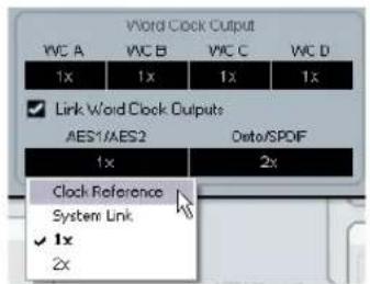
Setting the clock reference in Nuendo
In the Project Synchronization Setup dialog, you can choose one of the six Clock Reference options from the Steinberg SyncStation section.
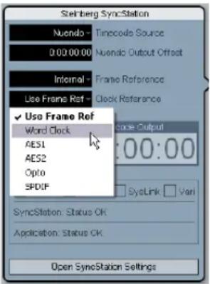
Choosing a clock reference for the SyncStation.
Clock 02 - System Clock Rate
Clock 02-System Clock Rate >48kHz >44.1kHz >32kHz
The SyncStation runs internally at one of three clock rates or sample rates. Other sample rates are derived from these base rates through the use of multipliers.
>48kHz
This is the standard video and film sampling rate. Most audio post studios will use this as the standard operating clock rate.
>44.1kHz
This is the audio CD standard sampling rate and is used mostly for music recording. There are exceptions and certain video productions might use this rate for certain applications.
>32kHz
You never know when you might need this sample rate. Even though it is not a professional standard in common use today, it is included to provide comprehensive support for legacy devices.
The SyncStation uses a multiplier system to achieve high-resolution clock rates, see "Word clock" on page 10 for details.
Clock rate in Nuendo
When the SyncStation is connected to Nuendo and the clock is not derived by any other signal (Frame Reference set to Internal and Clock Reference to Use Frame Ref), the clock rate will be determined by the Project Setup settings. If the sample rate is above 48kHz , the SyncStation will choose the rate that is an even multiple of the project's rate. For example, if the project is running at 96kHz , the SyncStation will be set to 48kHz .
If you are using higher sample rates, you will have to properly set the word clock and AES/SPDIF output multipliers to ensure your devices are getting correct clock rates.
Clock 03 - Audio Pull/Varispeed 0.1%
Clock 03-Pseudo Pull/Varispeed 0.1% >Off >-0.1% >+0.1%
When dealing with audio transfers from a film shoot, it can be necessary to pull the audio clock down by 0.1% in order to match the speed change resulting from a film transfer to NTSC video. Or you might be correcting for a poorly performed transfer and have to pull-up the clock rate.
There are two audio pull settings in SyncStation, one for 0.1% and another for 4% . The combination of the two pull settings yields all the possible pull-up and pull-down settings.
>Off
The audio clock runs at the chosen rate.
>0.1%
The audio clock is slowed by 0.1% . For example, using 48kHz as the clock rate with a -0.1% pull-down results in a sample rate of 47.952kHz.
>0.1%
The audio clock is sped up by 0.1% . 48kHz pulled-up yields 48.048kHz.
Clock 04 - Audio Pull/Varispeed 4 %
Clock 04-Hudio Full/Varispeed 4% >Off >-4.0% >+4.1667%
4% pulls are most often associated with PAL video transfers. For example, when transferring PAL video to film, a -4% pull down is applied to achieve 24fps.
>Off
The audio clock runs at the chosen rate.
-4.0%
Used for PAL video to film.
> +4.1667%
Used for film to PAL video.
There might be situations where you need to use a combination of both 4% and 0.1% pulls to correct for a problem. The SyncStation allows you the flexibility to do just that.
Audio pull in Nuendo
Nuendo's Project Setup settings include a "Pull Up/ Pull Down" menu to make the pull settings. The various combinations are made in Nuendo with single choices instead of separate settings for 4% and 0.1% pulls.
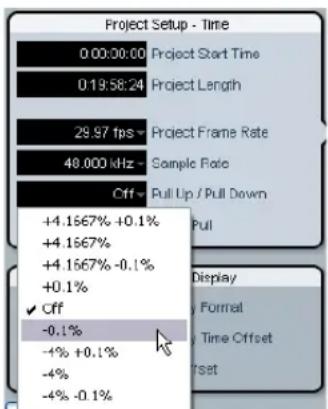
Audio pull in the Project Setup section

The Nuendo pull up/down settings will only be transmitted to the SyncStation if the "Hardware Pull Settings" option is set to "Follow Nuendo" (SyncStation Settings pop-up window, Audio Pull section).
Varispeed in Nuendo
It is possible to run the SyncStation in full varispeed mode. This gives you the option to vary the clock speed ± 12.5% in increments of 0.1% . In this state, the SyncStation cannot lock to timecode and the clock generator will run independently of the clock reference.
Varispeed is accessed from the SyncStation Settings pop-up window in the Audio Pull section. Choose Varispeed from the "Hardware Pull Settings" pop-up menu and enter a varispeed amount in the field below.
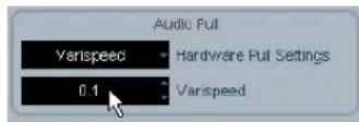
Varispeed setting in the SyncStation Settings pop-up window
Clock 05 - Wordclock A
Clock 05-wordclock A
Off >w/C In >1x >2x >4x >256x
The Clock 05 to Clock 08 settings deal with the way the clock is generated at the word clock outputs. Each output can be individually configured to provide much flexibility for various studio setups.
>Off
When set to "Off", that word clock output will not have any signal at all.
W/C In
When the word clock output is set to "W/C In", it will echo whatever word clock signal is coming in via the word clock input. This is important when you are using the word clock input as the clock reference. For the best audio fidelity, use this option in order to have the cleanest word clock signal pass through the SyncStation to your audio device.

When using the word clock input as the clock reference, it is necessary that the incoming word clock signal is generated by the same clock source as the chosen frame reference or at the very least is tied to the frame reference by another device. The best example of this is using one generator to create both the video sync and word clock signals.
>1x
When set to 1x , the word clock output signal is generated by the SyncStation and referenced to the chosen clock reference. It will run at the rate set in "Clock 02 - Clock Rate".
>2x
The 2x setting multiplies the master clock rate in the SyncStation to output a rate twice as fast. If the clock rate is set to 48kHz , the word clock output would run at 96kHz for example.
>4x
The 4x setting allows word clock output rates up to 192kHz
>256x
The 256x multiplier is a special use for synchronizing Digidesign hardware units that use this proprietary word clock signal.
Clock 06 - Wordclock B
Settings for the second word clock output.
Clock 07 - Wordclock C
Settings for the third word clock output.
Clock 08 - Wordclock D
Settings for the fourth word clock output.
Changing the word clock output in Nuendo
In Nuendo's Project Synchronization Setup dialog, click the "Open SyncStation Settings" button to access the word clock output settings.
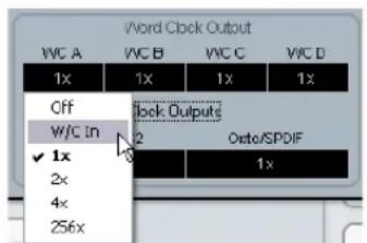
SyncStation Settings pop-up window with "Word Clock Output" setting menu
All four word clock outputs can be linked together so that changing the setting of one output affects all others in the same way.
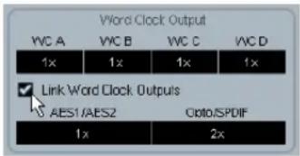
Word clock output link
Clock 09 - AES 1/AES 2 Output
Clock 89-RES1/RES2 Output
Clk Ref I/P >Slink I/P >1x Clk >2x Clk
The two AES outputs can be set to follow the clock reference input, the System Link input or the internal generator running at 1x or 2x rates.
>Clk Ref I/P (Clock Reference)
The AES clock will be generated from the clock reference input as set in menu Clock 01.
> Slink I/P (System Link Input)
The AES clock will be generated from the System Link input set in menu Unit 05. The extended System Link does not have to be active in the SyncStation. However, other System Link signals will be passed from the AES inputs to the outputs so that normal System Link operation is possible through the SyncStation.
>1x Clk (Clock)
The AES output will be generated by the SyncStation at the master clock rate.
>2x Clk (Clock)
The AES output will run at twice the master clock rate.
Setting the AES clock outputs in Nuendo
The AES clock output setting can be found below the "Word Clock Output" settings in the SyncStation Settings pop-up window.
The AES output settings
Clock 10 - Opto/SPDIF Output
Clock 10-Opto/SPDF
Clk Ref I/P >Slink I/P >1x Clk >2x Clk
The SPDIF and Toslink outputs can have a separate setting from the two AES outputs with the same choices for clock generation (see above). Both outputs will use the same setting.
Ck Ref I/P
- System Link I/P
1x
2x
Please note that the SyncStation back panel optical connector can only be used for SPDIF signals (and not for ADAT signals).
Setting the Opto/SPDIF outputs in Nuendo
The Opto/SPDIF output setting can be found right next to the AES settings in the SyncStation Settings pop-up window (see above).
Clock 11 - Wordclock Input Rate
Clock 11-bordclock Input Rate >1x >2x >4x >256x
When using the word clock input as the clock reference, it may be necessary to determine its input divider if using word clock rates above 48kHz .
>1x
44.1 or 48kHz standard rates do not need a divider.
>2x
88.2 or 96kHz rates divided by two equal 44.1 and 48kHz , respectively.
>4X
172.4 or 192kHz rates when divided by four yield 44.1 or 48kHz respectively.
>256x
The 256 divider is for Digidesign Superclock only.
Changing the clock input divider in Nuendo
In Nuendo's Project Synchronization Setup dialog, this option only becomes available when word clock is chosen as the clock reference.
Setting the word clock input divider.
P2 Out menu
The P2 Out menu determines how the RS422 output handles various aspects of the 9-Pin device.
P2out 01 - Record Tracks
P2out 01-Record Tracks
Off >8 >16 >24 >32 >48 >48 >56 >64
The user can set the amount of record tracks available from the 9-Pin device if the SyncStation has not automatically determined the number from polling the device.
The amount of record tracks determines how many recordable buttons are available on the SyncStation 9-Pin device panel in Nuendo. Due to the menu structure of the SyncStation, you are limited to nine choices:
>Off
No track arming buttons will be available on the SyncStation's 9-Pin device panel when this is set to off.

The SyncStation will normally determine the amount of record tracks automatically for you by polling the device and using its internal reference of machine descriptions.
8...>64
Use these settings to set the corresponding number of tracks.
P2 audio track count in Nuendo
64 tracks is the maximum for track arming through the SyncStation. Even though you are limited to eight choices in the SyncStation, in Nuendo you can set any amount of record tracks by clicking in the audio track count field of the "Machine Control Output Settings" section in the Project Synchronization Setup dialog.
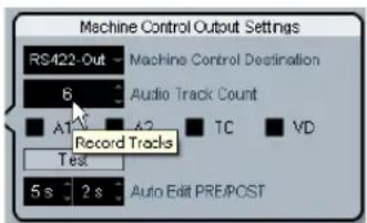
Entering the amount of tracks for the RS422 output device.
P2out 02 - Position Request
P2out 02-Position Request
LTC > UTC > L+U > Tim-1 > L+T+U
The RS422 protocol uses a question-and-answer polling system to determine the location of the connected device. When asking the question "Where are you?" to the 9-Pin device, it can use several internal sources to get an answer. That answer is then returned via the RS422 connection to the SyncStation.
In certain cases, it might be necessary to instruct the device to only answer using specific internal sources. This menu setting determines what those internal sources are.
> LTC
Most VTRs have an LTC source as part of the tape format. It can be read internally and then communicated back via RS422 to the SyncStation.
>VITC
This is the most accurate form of timecode since it is physically tied to the video frame signal.
> L+V
This uses a combination of LTC and VITC.
>Tim-1(Timer1)
Timer 1 is yet another source of location information inside VTRs. Only in certain circumstances would you want the position request to come only from the Timer 1 source.
> L+V+T
This is the default setting and uses a combination of all three sources for a position request.
Position request setting in Nuendo
In Nuendo, you can access this setting by selecting an option from the "Position source" pop-up menu in the SyncStation Settings pop-up window.
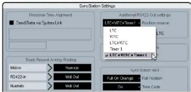
Selecting the RS422 position request sources.
P2out 03 - Position From
P2out 03-Position From
Serial >Serial+LTC Reader
This is an extension of the position request setting, allowing you to also use the LTC reader in the SyncStation as a source of position information when the timecode source is set to RS422 Out. While the serial 9-Pin connection can communicate position using LTC internally, the addition of the SyncStation's LTC reader can be useful in certain situations where there is an issue.
>Serial
This uses the serial 9-Pin RS422 connection exclusively for position requests.
>Serial+LTC Reader
This allows the LTC reader to be used as another source of position information for the SyncStation when RS422 is set as the timecode source.
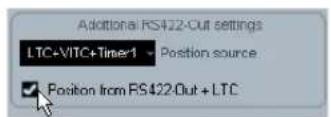
Position from setting in Nuendo
In Nuendo, this setting can be changed from the SyncStation Settings pop-up window with the "Position from RS422-Out+LTC" check box. When deactivated, the SyncStation will use the serial port only.
P2 In menu
The RS422 input is used to remotely control the SyncStation as a virtual machine from an external master controller. When enabled, the SyncStation will appear as another 9-Pin device to the external controller.
P2in 01 - Device ID
P2in 61-Device ID
RS422-Out >Nuendos >Nuendot >3324 >P500
The external controller will identify the SyncStation by the ID set in this menu.
>RS422-Out
When set to RS422-Out, the SyncStation will identify itself to the controller as the same type of device that is connected to the SyncStation's 9-Pin out connector.
>Nuendos
Identifies the SyncStation as "Nuendo SyncStation".
>Nuendot
Identifies the SyncStation as "Nuendo Timebase".
>3324
Identifies the SyncStation as a Sony 3324 DASH Digital Multitrack machine.
>A500
Identifies the SyncStation as a Sony A500 VTR, a very common 9-Pin profile.
Setting the P2 In device ID in Nuendo
The P2 In device ID can be set in Nuendo from the Sync-Station Settings pop-up window by selecting an entry from the Device ID pop-up menu.
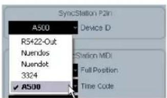
Setting the P2 In device ID to A500.
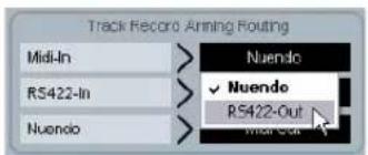
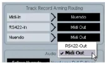
P2in 02 - RS422-In Track Arming
P2in 02-RS422-In Track Arming >Nuendo >RS422-Out >MIDI Out
Since the Virtual Master of the SyncStation does not have any tracks that can be record-enabled, those commands received from the external controller are diverted to another destination. Additionally, when a "record" command is received, it will also be routed to the destination set in this menu.
>Nuendo
Record and track arming commands will be sent to Nuendo via USB.
>RS422-Out
Record and track arming commands will be sent to the device connected to the RS422 Out.
>MDI Out
Record and track arming commands will be routed to the MIDI output.
P2 In track arming in Nuendo
The track arming can be set within Nuendo from the "Track Record Arming Routing" section in the SyncStation Settings pop-up window.
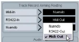
Setting the RS422-In track arming routing to MIDI Out.
MIDI menu
This menu contains settings regarding the MIDI input and output configuration.
MIDI 01 - MTC -> MIDI Out
MIDI 01-MTC > MIDI Out
On >Off
This determines if MTC is being sent via the MIDI output.
MIDI 02 - Full Position -> MIDI Out
MIDI 02-Full Position MIDI Out
Off >MFC Full >Full on change >Locate
This setting deals with how MTC is relayed to the MIDI output. MTC has two basic messages, quarter-frame and full-frame. Full-frame messages are SysEx data that contain the complete timecode number. Full-frame messages are used to locate devices to specific points.
Quarter-frame messages are only used during playback and only contain a partial timecode number. It takes 8 quarter-frame messages for the complete timecode number to be transmitted. Quarter-frame messages are used during playback to maintain sync.
This setting determines what message is sent when the timecode source changes position in Stop mode.
>Off
No full-frame messages will be sent at all.
>MMC Full
Full-frame messages will be sent constantly.
>Full on change
This is the default setting and should work for most cases. Full-frame messages are sent when the position of the master changes, such as when locating to a new position. During playback, only quarter-frame messages will be used.
>Locate
The MMC locate command is slightly different from "Full on change". Some devices will react to this mode better than others.
MIDI full position setting in Nuendo
MTC, Full Position and MIDI Device ID can all be set within Nuendo from the SyncStation MIDI section in the SyncStation Settings pop-up window.
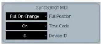
The MIDl settings in the SyncStation Settings pop-up window
MIDI 03 - MIDI In Track Arming
MIDI 03-MIDI In Track Arring >Nuendo >RS422-Out
This setting is independent of the RS422 In record and track arming, but performs the same function for MMC commands from the MIDI input.
>Nuendo
Routes all record and track arming commands to Nuendo via USB.
>RS422-Out
Routes all record and track arming commands to the RS422 output.
MMC record and track arming in Nuendo
The MIDI track arming can be set from the "Track Record Arming Routing" section within the SyncStation Settings pop-up window.
Changing the routing for MIDI track record arming
MIDI 04 - MIDI ID
MIDI 04-MIDI ID
0 >1 >2 >3 >4 >5 >6 >7 >8 >All(7f)
This determines the MIDI device ID used by the commands sent out via the MIDI Out.
Changing the MIDI device ID in Nuendo
You can change the MIDI device ID by selecting a value from the Device ID pop-up menu in the SyncStation Settings pop-up window.
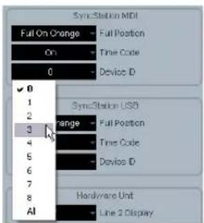
Changing the MIDI device ID.
USB menu
This menu deals with the USB connection to the Nuendo host computer and the MIDI communication between the SyncStation and Nuendo.
USB 01 - MTC -> Nuendo
USB 01-MTC -> Cuendo
>On >Off
This determines if MTC is transmitted to Nuendo via USB. If this is set to Off, Nuendo cannot start playback because the SyncStation will not transmit incoming timecode.
USB 02 - Full Position -> Nuendo
USB 02-Full Position -> Nucleo
>Off >MMC Full >Full on change >Locate
This determines the usage of full-frame MTC messages going to Nuendo. Just as with the MIDI Out setting, the "Full on change" setting will work for most conditions, but the others are available for certain circumstances.
>Off
No full-frame messages will be sent.
>MMC Full
Constant full-frame messages will be sent.
>Full on change
Default sends full-frames only when position changes and not during play. Using this option is recommended since it allows you to avoid generating too much MIDI traffic.
>Locate
MMC locate commands will be sent.
USB 03 - Nuendo Track Arming
USB 03-Nuendo Track Arming >RS422-Out >MIDI Out
This setting is independent of the MIDI and RS422 track arming settings. Track arming buttons on the SyncStation 9-Pin device panel will be routed according to this setting. Also, record commands sent by Nuendo's transport when sync is enabled will be routed to the same destination. This can be used to perform remote layback on any connected device.
>RS422-Out
All record and track arming commands will be sent to the connected 9-Pin device.
>MIDI Out
All record and track arming commands will be sent to the MIDI output.
Changing the USB track arming in Nuendo
You can change Nuendo's track arming by selecting a value from the Nuendo pop-up menu in the "Track Record Arming Routing" section in the SyncStation Settings pop-up window.
Setting the Nuendo track arming to MIDI Out.
USB 04 - Nuendo MIDI ID
USB 04+Huendo MIDI ID
>0 >1 >2 >3 >4 >5 >6 >7 >8 >All(7f)
Sets the MMC ID number for Nuendo for receiving MMC commands from the MIDI input.
Setting the USB MIDI device ID in Nuendo
The MIDI ID, MTC and Full Position settings can be made in the SyncStation Settings pop-up window from the SyncStation USB section.
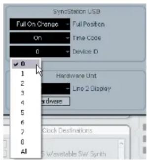
Choosing a MIDI ID for Nuendo.
USB 05 - USB Driver
USB 05-USB Driver
MI DI Class >Steinberg
This determines which driver the SyncStation will use to connect to the host USB bus. The default setting is "Steinberg" but it may be necessary on some systems to use the MIDI Class driver.
Changing the USB driver requires a restart of the SyncStation.
Windows XP will not allow Nuendo to recognize the SyncStation when set to the MIDI Class driver. Always use the Steinberg setting with Windows XP systems.
You cannot change the USB driver from within Nuendo.
Example Studio Setups
Using three example studios, we will go step-by-step through the process of connecting the SyncStation in each system.
Composer's home studio
In this first example, a personal project studio that functions as a composer's suite for film and television music will be used. System Link is used to connect two audio workstations; a main Nuendo system for editing and mixing and a Cubase system for running VSTi instruments and external MIDI devices. A Digital Betacam VTR is used to layback finished cues to videotape. Additionally, an Alees HD 24 hard disk recorder is used to print stems to mix at a dubbing theater.
- Nuendo system
Cubase VSTi system
Alesis HD 24 hard disk recorder
Digital Betacam VTR
In this example, the SyncStation will be used as the master clock source for all the audio equipment in the studio. Each of the word clock outputs is connected to the two audio cards for the Nuendo and Cubase systems plus another word clock connection to the HD 24. Since there is no other video equipment involved besides the Betacam deck, video sync will come from the VTR.
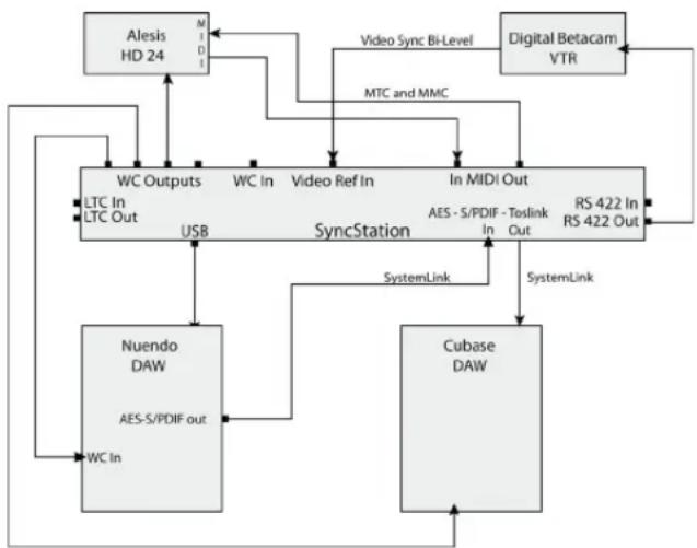
Example connections for a composer's home studio
Machine control is used to control and sync with the Betacam VTR via RS422. Also, MMC is used to remotely arm tracks on the HD 24. Since a Digital Betacam deck is standard definition, only bi-level video sync is used as the frame reference. Timecode from the Betacam is communicated over the RS422 protocol and will be used as the timecode source in the SyncStation.
Extended System Link connections
Notice that there are two System Link connections, the extended connection used by the SyncStation for sample-accurate positioning and the normal connection between Steinberg DAWs via the SyncStation.
Note that the extended System Link connection only goes one way, from the audio card in the Nuendo system to one of the three digital inputs of the SyncStation.
In order to use one of the digital outputs of the SyncStation to pass System Link on to other Steinberg DAWs, Menu Clock 09 or 10 would be set to SLink I/P in order for System Link signals to pass through the SyncStation.

When using the extended System Link connection to the SyncStation, all System Link settings must be made via the SyncStation's front panel or the SyncStation Settings pop-up window in Nuendo. The Nuendo System Link setup in the Devices menu cannot be used while the extended System Link is engaged.
SyncStation settings for home studio example
- Master & Timecode Source = RS422 Out
- Frame Reference = Video
- Clock Reference = Use Frame Ref
·Wordclocks = 1x - Precision Alignment System Link = On
- Track Arming Routing = Nuendo > RS422 or MIDI
- Nuendo Machine Control Output = SyncStation (RS422)
Mid-level post-production suite
This example involves a dedicated audio for video postproduction studio that is involved in audio editing, foley and voice recording, multi-channel mixing, and DVD authoring. This studio includes a high-quality computer video card that is used to capture video and audio from a Digital Betacam VTR. A master video clock generator is used to ensure frame edge accurate operation from the Digital Betacam, video card, and Nuendo.
- Nuendo system
Virtual VTR computer with BlackMagic card
House tri-level video sync generator - Various VTRs via machine room router
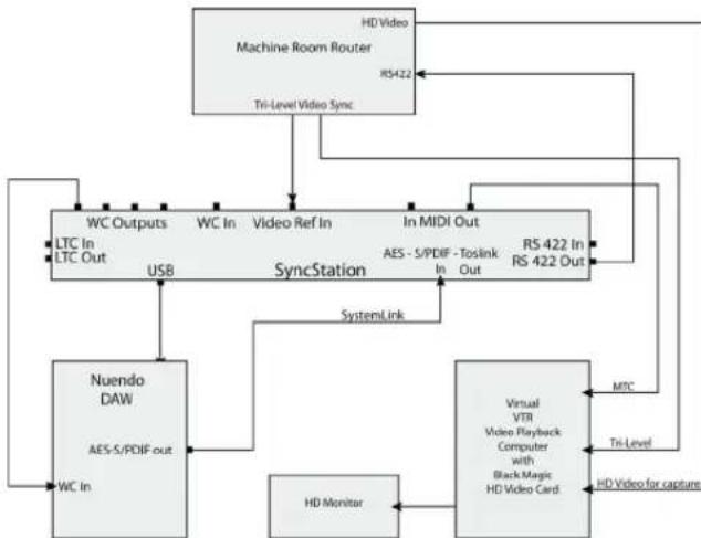
A mid-level post-production studio with a central machine room
In this example, tri-level video sync is used to synchronize Nuendo's playback to the house sync generator in the machine room of the facility. The SyncStation's RS422 output is fed into the router where it can be connected to any VTR in the machine room.
SyncStation settings for post suite example
- Master & Timecode Source = RS422 Out for video capture and layback or Nuendo for editing
- Frame Reference = Video
- Clock Reference = Use Frame Ref
- Word clocks = 1 x
- Machine Control Output = SyncStation (RS422)
- Precision Alignment System Link = On
- Track Arming Routing = Nuendo > RS422
Film dubbing theater
The most complex example is a fully-fledged dubbing stage where feature films and high-profile television shows are mixed. This example involves dedicated video playback for a large projection system, multiple Nuendo and other DAW systems to handle audio playback and surround mixing, plus a large, multi-seat control surface for mixing including machine control and track arming for dubbers.
- Nuendo system
Pro Tools system - Console's 9-Pin controller
- Nanosync tri-level video sync and word clock generator
Bonsai HD video player
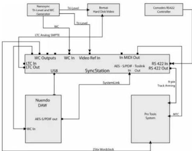
A sample dub stage setup using a RS422 master controller
In this example, Nuendo is synchronized with a Bonsai HD video player and a Pro Tools system. All of this is controlled by the main console's RS422 controller, allowing the transport controls of the console to run the entire system.
In this setup, the SyncStation is the Virtual Master, generating timecode for all devices. Both the console and Nuendo can start and stop playback or locate the system. The Nanosync generator is used for both the frame reference input and the word clock input. A 256x word clock is being fed to the Pro Tools system along with MTC. Pro Tools is also connected via RS422 Out for record-arming tracks and punching in. The Bonsai locks to LTC and is video gen-locked to the tri-level sync.
SyncStation settings for dub stage example
Timecode Source = Virtual Master
- Frame Reference = Video
- Clock Reference = Word clock
- Wordclocks = 1x and 256x
- Machine Control Output = SyncStation (RS422)
- Machine Control Input = SyncStation
- SyncStation P2 In = A500
- Precision Alignment System Link = On
- Track Arming Routing = Nuendo > RS422
Technical Data
Specifications GPIO pin assignment
Connections 5V DC input
USB 1.1
Timecode In/Out (XLR)
MIDI In/Out
Video Sync In/Thru (BNC) SD/HD,
bi-level/tri-level signals
Word Clock In (BNC)
Word Clock Out A-D (BNC) up to 192kHz
AES In/Out (XLR) up to 96kHz
AES In/Out (BNC) up to 96kHz
SPDIF In/Out (Coax) up to 96kHz
SPDIF In/Out (Optical) up to 96kHz
RS422 In/Out (9' D' connector)
General Purpose In/Out interface
(25' D' single connector)
External Input AC 100-240V 50/60Hz 0.4A 30VA; power-supply Output DC 5V 2A
Dimensions Front-panel 19" rack-mountable
48.3 x 4.4 x 17.5cm
Weight 1.4kg
Display 14.7 × 1.2 cm (2x40 characters)
GPI-In Function (Active low)
3 Stop Momentary
4 Play Momentary
5 Record Off Momentary
6 Record On Momentary
7 Record Continuous
8 On-Line
9
10
GPI-Out Function (Active Low)
16
17 SyncStation Lock
18 Record Off Momentary
19 Record On Momentary
20 Record Continuous
21 On-Line
22 Nuendo Lock
Wiring diagrams can be found on the Steinberg web site at http://service.steinberg.de/goto.nsf/show/supportupdates_SYNCstation_en.
FCC information (U.S.A.)
Note: This equipment has been tested and found to comply with the limits for a Class A digital device, pursuant to part 15 of the FCC Rules. These limits are designed to provide reasonable protection against harmful interference when the equipment is operated in a commercial environment. This equipment generates, uses, and can radiate radio frequency energy and, if not installed and used in accordance with the instruction manual, may cause harmful interference to radio communications. Operation of this equipment in a residential area is likely to cause harmful interference in which case the user will be required to correct the interference at his own expense.
Changes or modifications not expressly approved by the party responsible for compliance may void the user's authority to operate the equipment.
Compliance Information Statement (Declaration of Conformity Procedure)
This device complies with part 15 of the FCC Rules. Operation is subject to the following two conditions:
- This device may not cause harmful interference, and
- this device must accept any interference received, including interference that may cause undesired operation.
CE Declaration of Conformity
We, Steinberg Media Technologies GmbH, Neuer Hoeltigbaum 22-32, 22143 Hamburg, Germany, declare under our sole responsibility that the product
Nuendo SyncStation
to which this declaration relates is in conformity with the following standard(s) or other normative document(s):
Disturbance Emission
EN 55022:1998 + A1:2000 + A2:2003
EN 55022:1998 + A1:2000 + A2:2003
EN 61000-3-2:2000 Limits
EN 61000-3-3:1995 + A1:2001 Limits
EN 55103-1:1996 magnetic field emission test
The limits and requirements according to EN 55103-1:1996
Immunity Interference
EN 61000-4-11:1994
EN 61000-4-5:1995 + A1:2001
EN 61000-4-4:1995 + A1:2001 + A2:2001
- EN 61000-4-2:1995 + A1:1998
EN 61000-4-6:1996 +A1:2001
EN 61000-4-3:2002 + A1:2002
EN 55103-2:1996
The limits and requirements according to EN 55103-2:1996
Handling warranty issues
Go to www.steinberg.net/warranty to find the Steinberg Statement of Warranty, and information on the handling of warranty issues. This web page also contains the End User License Agreements for Steinberg software products. All documents are available as printable PDF files.
Updating the SyncStation driver
To operate the SyncStation via the USB port of your computer, a driver software corresponding to the operating system of your computer must be installed.
You can find this driver on the Nuendo installation disk included in your SyncStation package, in the "Drivers" folder. The drivers are also available in the following location: http://service.steinberg.de/goto.nsf/show/supportupdates_SYNCstation_en
Be sure to check for updates at regular intervals.
A "SyncStation Driver Installation-en.txt" file explaining the installation procedure for Windows and Mac OS computers can also be found inside the "Drivers" folder on the Nuendo DVD, and in the following location: http://service.steinberg.de/goto.nsf/show/supportupdates_SYNCstation_en
Updating the SyncStation firmware
Steinberg supplies the firmware running in the SyncStation as a separate downloadable package in the following location:
http://service.steinberg.de/goto.nsf/show/
supportupdates_SYNCstation_en
A "Readme" file explaining the installation procedure for this package can also be found in this location. Be sure to check for updates at regular intervals.
Index
A
AES 10, 14, 15, 19, 26
AES clock outputs
Setting in Nuendo 30
Setting in SyncStation 29
Audio pull
Setting in Nuendo 28
Setting in SyncStation 27
Auto-Edit 20
B
Bi-level sync (video black burst) 10
C
Clock distribution 7
Clock outputs
Setting in Nuendo 29
Setting in SyncStation 28
Slave devices 15
Status on SyncStation display 19
Clock rate
On SyncStation display 19
Setting in Nuendo 27
Setting in SyncStation 27
Clock reference
Inputs 15
LED 17
LTC 10
MTC 10
On SyncStation display 19
Setting in Nuendo 27
Setting in SyncStation 26
Video 10
Clock sources 10
Current position display 18
Cursor buttons 17
Cursor LED 17
D
Display modes
About 18
Operation mode 18
Settings Menu mode 19
E
Extended System Link
About 7
Setting in Nuendo 25
Setting in SyncStation 25
USB14
F
Factory settings (recall) 26
Film 8,9,18,25
Frame count 9
See also "Timecode standard"
Frame rate
About 9
On SyncStation display 18
Frame reference
About 11
Inputs 15
LED17
On SyncStation display 18
Setting in Nuendo 24
Setting in SyncStation 24
Front panel
Cursor buttons 17
Cursor indicator 17
Overview 17
Reset button 17
Status LEDs 17
Full/Quarter-frame messages via
MIDI
Setting in Nuendo 34
Setting in SyncStation 33
Full-frame messages via USB
Setting in SyncStation 35
G
GPIO 14
About 8
Connection 15
Pin assignment table 42
H
HD video 10, 11
1
Inputs on rear panel 14
L
LCD screen
Display modes 18
Line 2 display 19
Resetting 17
LTC8,10,11,12,14,15,18,24,31
LTC reader 19, 32
M
Machine control
9-Pin RS422 12
9-Pin window in Nuendo 20
About 7
Connections 15
MMC12
Track arming commands 11
Transport commands 11
Virtual Machine Master 11
MIDI device ID
Changing in Nuendo 34
Changing in SyncStation 34
MIDI In 15
MIDI In/Out 14
MIDI Machine Control 12
MIDI Out 33, 35
MIDI-In Track Arming
Setting up in Nuendo 34
Setting up in SyncStation 34
MTC8,10,11,18,19,23,24,33,35
N
NTSC 9,18,25
Nuendo
Connecting to the SyncStation 14
Resetting the SyncStation 20
Status on SyncStation display 19
SyncStation 9-Pin window 20
SyncStation Status window 20
Transport commands 12
Nuendo Timebase 32
Nuendo track arm
Setting in Nuendo 35
Setting in SyncStation 35
0
Operation (display mode) 18
Opto/SPDIF outputs
Setting in Nuendo 30
Setting in SyncStation 30
Outputs on rear panel 14
P
P2 In device ID
Setting in Nuendo 32
Setting in SyncStation 32
PAL 9,18,25,28
Phase (frame reference) 11
Position from setting
In Nuendo 32
In SyncStation 32
Position request setting
In Nuendo 32
In SyncStation 31
Position source setting 32
Precision Time Alignment 25
Pull up/down 9, 19
See also "Audio pull"
R
Rear panel inputs/output 14
Recall factory settings 26
Record track count
Setting in Nuendo 31
Setting in SyncStation 31
Reference frame rate
Setting in SyncStation 25
Reset button 17
Reset Hardware button in Nuendo 20
Root menu (Settings Menu display mode) 19, 23
RS4228,12,14,15,19,23,32,33 34,35
RS422-In Track Arming
Setting up in Nuendo 33
Setting up in SyncStation 33
s
Sample rate, see "Clock rate"
Settings Menu
Basic settings (Unit menu) 23
Changing settings 20
Clock settings 26
MIDI In and Out settings 33
Overview of menu system 22
Root level 19
Settings for 9-Pin devices 31, 32
USB-related settings 35
Slave clocks 15
SMPTE 9,18
Sony A500 32
Sony P2 8, 15
SPDIF 10, 14, 15, 19, 26, 27
Speed (frame rate) 9
Standard frame rates 9
Status LEDs 17
Status window in Nuendo 20
Synchronization 8
SyncStation driver 44
SyncStation firmware 44
System Link input
Selecting in Nuendo 26
Selecting in SyncStation 25
System Link LED 17
T
Technical data 41
Timecode
About 8
Frame count 9
Frame rate 9
Timecode source
Selecting in Nuendo 24
Selecting in SyncStation 23
SyncStation display 18
Timecode standard
Setting in SyncStation 25
SyncStation display 18
Timecode synchronizer 7
Toslink 15
Toslink Optical (Opto) 10, 14, 19, 26
Track arming 11
Transport status icons 18
Tril-level sync (video) 10
U
USB connection 14
USB driver
Changing in SyncStation 36
Resetting 17
USB MIDI device ID
Setting in Nuendo 35
Setting in SyncStation 35
USB status display 18
V
Varispeed 19, 27, 28
Setting in Nuendo 28
Varispeed indicator 20
Video 11, 18, 24
Video black burst 10
Video frame rate 10
Video sync 10, 11, 14, 15, 24, 26
Virtual Master 11, 19, 23, 25
VITC8,31
W
Warranty information 44
Word clock 10, 14, 15, 19, 26, 28
Word clock input divider
Setting in Nuendo 30
Setting in SyncStation 30
Benutzerhandbuch
GPIO (General Purpose In/Out)
- 30fps Non-Drop SMPTE (N)
Video Sync In
- Word clock In
A E S 1 I n
AES21n
- SPDIF In
Optical Toslink In
MIDI In
LTCIn
- Sony P2 (9-Pin, RS422) In
Unit >Clock >P2out >P2in >MIDI >USB
Unit 01 - Master & Timecode Source
Unit 01-Master & Timecode Source
Nuendo >RS422-Out >NTC >UMast >LTC
Internal >Video >LTC >MTC
>Pal (Pim SyncStation-Display)
25 Frames pro Sekunde Timecode.
Unit 05 - System Link
Unit 05-System Link >Off >On
Unit 08 - Line 2 Display
Unit 08-Line 2 Display
>Frm (Use Frame Reference)
Clock-Rate in Nuendo
Clock 03 - Audio Pull/Varispeed 0.1%
Clock 03-Audio Pull/Varispeed 0.1% >Off >0.1% >+0.1%
Clock 04-Audio Pull/Varispeed 4% >Off >-4.8% >+4.1667%
Audio-Pull in Nuendo
Clock 05-wordclock A
Off >w/C In >1x >2x >4x >256x
Clock 09 - AES 1/AES 2 Output
Clock 99-PES1/PES2 Output
Clk Ref I/P >Slink I/P >1x Clk >2x Clk
Clock 11-wordclock Input Rate >1x >2x >4x >256x
P2out 03 - Position From
P2out 03-Position From
Serial >Serial+LTC Reader
P2in 02 - RS422-In Track Arming
P2in 02-RS422-In Track Arming >Nuendo >RS422-Out >NIDI Out
Off >MMC Full >Full on change >Locate
USB 62-Full Position -> Huendo
Off >MFC Full >Full on change >Locate
USB 03 - Nuendo Track Arming
USB 03-Nuendo Track Arming >RS422-Out >MI DI Out
LTC 54, 57, 59, 61, 62, 65, 72, 80
LTC-Reader 66,81
M
Machine Control
9-Pin RS422 58
9-Pin-Fenster in Nuendo 67
Pull-Up/-Down 55, 66
GPIO (General Purpose In/Out)
- SMPTE non-drop 30ips (N)
·P = P A L 2 5 i p s
- N = NTSC SMPTE 30ips
- D = SMPTE Drop-frame 30ips
F = Film 24ips
État du transport
Unit >Clock >P2out >P2in >MIDI >USB
Unit 01 - Master & Timecode Source
Unit 01-Master & Timecode Source
Nuendo >RS422-Out >NTC >Umat >LTC
You've already chosen the cinq sources for Timecode:
>Nuendo
Internal >Video >LTC >MTC
Unit 05 - System Link
Unit 05-System Link >Off >On
Unit 08 - Line 2 Display
Unit 68-Line 2 Display
Clock 03 - Audio Pull/Varispeed 0.1%
Clock 03-Audio Pull/Varispeed 0.1% >Off >0.1% >+0.1%
Clock 04-Audio Pull/Varispeed 4% >Off >-4.8% >+4.1667%
Clock 05-wordclock A
Off >W/C In >1x >2x >4x >256x
Clock 09 - AES 1/AES 2 Output
Clock 09-AES1/AES2 Output
Clk Ref I/P >Slink I/P >1x Clk >2x Clk
Clock 11-wordclock Input Rate >1x >2x >4x >256x
P2out 03 - Position From
P2out 03-Position From
Serial >Serial+LTC Reader
P2in 02 - RS422-In Track Arming
P2in 02-RS422-In Track Arming >Nuendo >RS422-Out >MIDI Out
Off >MMC Full >Full on change >Locate
Off >MFC Full >Full on change >Locate
USB 03 - Nuendo Track Arming
USB 03-Nuendo Track Arming
RS422-Out >MI DI Out
MIDI In Track Arming
Position from (Réglage)
RS422-In Track Arming
Configurer dans la
SyncStation 130
- Introduction
- Connecting the SyncStation
- SyncStation Controls
- Menu Reference
- Example Studio Setups
- Technical Data
- Index
- About this manual
- What can the SyncStation do?
- Clock distributor
- Machine control
- Timecode synchronizer
- SyncStation extended System Link
- GPIO (General Purpose In/Out)
- Synchronizing with the SyncStation
- Synchronization basics
- Timecode (positional references)
- Frame count (frames per second)
- 24fps Film (F)
- - 25fps PAL (P)
- - 30fps non-drop SMPTE (N)
- - 30fps drop-frame SMPTE (D)
- Frame rate (speed)
- 23.9fps
- 24fps
- 24.9fps
- 25fps
- 29.97fps
- 30fps
- - 59.98fps
- Clock sources (speed references)
- Internal generator
- Video black burst and tri-level sync
- Word clock
- AES Audio Clock
- SPDIF and Opto
- Video, LTC and MTC (using frame reference)
- Frame reference (phase)
- Internal
- Video
- LTC
- ·MTC
- Transport commands
- Track arming commands
- Virtual Machine Master (VMast)
- 9-Pin RS422
- MIDI Machine Control (MMC)
- Nuendo transport
- The inputs and outputs on the SyncStation rear panel
- USB connection
- Frame and clock reference inputs
- Slave clocks (outputs)
- GPIO (General Purpose Input Output)
- Front panel controls
- Cursor buttons and indicator
- Status LEDs
- Frame reference
- Clock reference
- System Link
- Reset button
- The SyncStation display
- Operation display mode
- Timecode source
- Timecode standard
- Transport status
- Current position
- USB status
- = USB is connected
- Frame reference or Frame rate
- Clock reference
- System clock rate
- Line 2 display
- Settings Menu display mode
- Root menu
- Changing Settings
- Resetting the SyncStation from Nuendo
- The SyncStation 9-Pin window in Nuendo
- Auto-Edit
- The SyncStation Status window in Nuendo
- Unit menu
- Unit 01 - Master & Timecode Source
- >Nuendo
- >RS422-Out
- >MTC
- >VMast (Virtual Master)
- > LTC
- Setting the timecode source in Nuendo
- Unit 02 - Frame Reference
- >Internal
- >Video
- Changing the frame reference in Nuendo
- Unit 03 - Timecode Standard
- >Pal (P in SyncStation display)
- >NonDrop (N in SyncStation display)
- >Film (F in SyncStation display)
- >Drop (D in SyncStation display)
- Unit 04 - Reference Frame Rate
- Unit 05 - System Link
- >Off
- >On
- Setting up System Link from Nuendo
- Unit 06 - System Link Input
- >AES1
- >AES2
- >Opto
- >SPDIF
- Choosing the SyncStation System Link input in Nuendo
- Unit 07 - Install Template
- Unit 08 - Line 2 Display
- Clock menu
- Clock 01 - Clock Reference
- >Frm (Use Frame Reference)
- >W/C (Word Clock)
- Setting the clock reference in Nuendo
- Clock 02 - System Clock Rate
- >48kHz
- >44.1kHz
- >32kHz
- Clock rate in Nuendo
- Clock 03 - Audio Pull/Varispeed 0.1%
- >0.1%
- Clock 04 - Audio Pull/Varispeed 4 \%
- > +4.1667%
- Audio pull in Nuendo
- Varispeed in Nuendo
- Clock 05 - Wordclock A
- W/C In
- >1x
- >2x
- >4x
- >256x
- Clock 06 - Wordclock B
- Clock 07 - Wordclock C
- Clock 08 - Wordclock D
- Changing the word clock output in Nuendo
- Clock 09 - AES 1/AES 2 Output
- >Clk Ref I/P (Clock Reference)
- > Slink I/P (System Link Input)
- >1x Clk (Clock)
- >2x Clk (Clock)
- Setting the AES clock outputs in Nuendo
- Clock 10 - Opto/SPDIF Output
- Setting the Opto/SPDIF outputs in Nuendo
- Clock 11 - Wordclock Input Rate
- Changing the clock input divider in Nuendo
- P2 Out menu
- P2out 01 - Record Tracks
- P2 audio track count in Nuendo
- P2out 02 - Position Request
- >VITC
- > L+V
- >Tim-1(Timer1)
- > L+V+T
- Position request setting in Nuendo
- P2out 03 - Position From
- >Serial
- >Serial+LTC Reader
- Position from setting in Nuendo
- P2 In menu
- P2in 01 - Device ID
- >Nuendos
- >Nuendot
- >3324
- >A500
- Setting the P2 In device ID in Nuendo
- P2in 02 - RS422-In Track Arming
- >MDI Out
- P2 In track arming in Nuendo
- MIDI menu
- MIDI 01 - MTC -> MIDI Out
- MIDI 02 - Full Position -> MIDI Out
- >MMC Full
- >Full on change
- >Locate
- MIDI full position setting in Nuendo
- MIDI 03 - MIDI In Track Arming
- MMC record and track arming in Nuendo
- MIDI 04 - MIDI ID
- Changing the MIDI device ID in Nuendo
- USB menu
- USB 01 - MTC -> Nuendo
- USB 02 - Full Position -> Nuendo
- USB 03 - Nuendo Track Arming
- >MIDI Out
- Changing the USB track arming in Nuendo
- USB 04 - Nuendo MIDI ID
- Setting the USB MIDI device ID in Nuendo
- USB 05 - USB Driver
- Composer's home studio
- Extended System Link connections
- SyncStation settings for home studio example
- Mid-level post-production suite
- SyncStation settings for post suite example
- Film dubbing theater
- SyncStation settings for dub stage example
- Specifications GPIO pin assignment
- GPI-Out Function (Active Low)
- FCC information (U.S.A.)
- Compliance Information Statement (Declaration of Conformity Procedure)
- CE Declaration of Conformity
- Nuendo SyncStation
- Disturbance Emission
- Immunity Interference
- Handling warranty issues
- Updating the SyncStation driver
- Updating the SyncStation firmware
- A
- B
- C
- D
- E
- F
- G
- H
- 1
- L
- M
- N
- 0
- P
- R
- s
- T
- U
- V
- W
- >Pal (Pim SyncStation-Display)
- Clock-Rate in Nuendo
- Clock 03 - Audio Pull/Varispeed 0.1\%
- Audio-Pull in Nuendo
- État du transport
Brand : STEINBERG
Model : Nuendo SyncStation
Category : Audio recorder