
HWA 4000 S - Pump METABO - Free user manual and instructions
Find the device manual for free HWA 4000 S METABO in PDF.
| Product type | Domestic surface pump |
| Brand | Metabo |
| Model | HWA 4000 S |
| Mains voltage | 230 V ~ 50 Hz |
| Rated power | 1300 W |
| Rated current | 4.5 A |
| Max. flow rate | 4000 l/h |
| Max. delivery head | 48 m |
| Max. delivery pressure | 4.8 bar |
| Max. suction lift | 8 m |
| Max. liquid temperature | 35 °C |
| Ambient temperature | 5 to 40 °C |
| Protection rating | IPX4 |
| Protection class | I |
| Dimensions (L x W x H) | 470 x 250 x 415 mm |
| Weight (empty) | 10.5 kg |
| Weight (filled with water) | 12.0 kg |
| Main functions | Pumping clean water for watering, irrigation, pool draining; self-priming; integrated pressure switch with dry-run protection |
| Maintenance | Drain water before frost; clean the suction filter if used |
| Safety | 30 mA residual current device recommended; do not pump flammable liquids; do not use in wet environment |
| Spare parts / Repairability | Repairs only by a professional electrician; mechanical seal, impeller, filter cartridge available |
Frequently Asked Questions - HWA 4000 S METABO
User questions about HWA 4000 S METABO
0 question about this device. Answer the ones you know or ask your own.
Ask a new question about this device
Download the instructions for your Pump in PDF format for free! Find your manual HWA 4000 S - METABO and take your electronic device back in hand. On this page are published all the documents necessary for the use of your device. HWA 4000 S by METABO.
USER MANUAL HWA 4000 S METABO
natural_image
Line drawing of a portable electric vacuum cleaner with attached cable (no text or symbols)P 3300 S
P 4000 S
natural_image
Line drawing of an electric motor with attached wires and sensors (no text or symbols)HWA 3300 S
HWA 4000 S

(D) Originalbetriebsanleitung. 5
ENG Original operating instructions ..... 11
F Instructions d'utilisation originales ..... 17
NL Origineel gebruik aanwijzing....24
⑭ Original brugsvejledning 30
ES Manual de instrucciones original ..... 36
① Πρωτότυπο οδηγιών λειτουργίας. . . . . . 43
SLO Izvirna navodila za uporabo.... 50
FIN Alkuperäiskäyttöohje 56
DE EN
EG-KONFORMITÄTSERKLÄRUNGVEC-DECLARATION OF CONFORMITY
We herewith declare in our sole responsibility that this product complies with the following standards* in accordance with the regulations of the undermentioned Directives** issuing test office *** measured/guaranteed noise sound power level****
NL
*** LWA = 83 dB/1pW - LWAd =90 dB/1pW
Director Innovation, Research and Development
Dokumentationsbevollmächtigter/ responsible person for documentation/ Chargé de la documentation
Metabowerke GmbH
Metabo-Allee 1
D - 72622 Nürtingen
DE EN
EG-KONFORMITÄTSERKLÄRUNGVEC-DECLARATION OF CONFORMITY
We herewith declare in our sole responsibility that this product complies with the following standards* in accordance with the regulations of the undermentioned Directives** issuing test office *** measured/ guaranteed noise sound power level****
NL
*** LWA = 86 dB/1pW - LWAd = 89 dB/1pW
Director Innovation, Research and Development
Dokumentationsbevollmächtigter/ responsible person for documentation/ Chargé de la documentation
Metabowerke GmbH
Metabo-Allee 1
D - 72622 Nürtingen
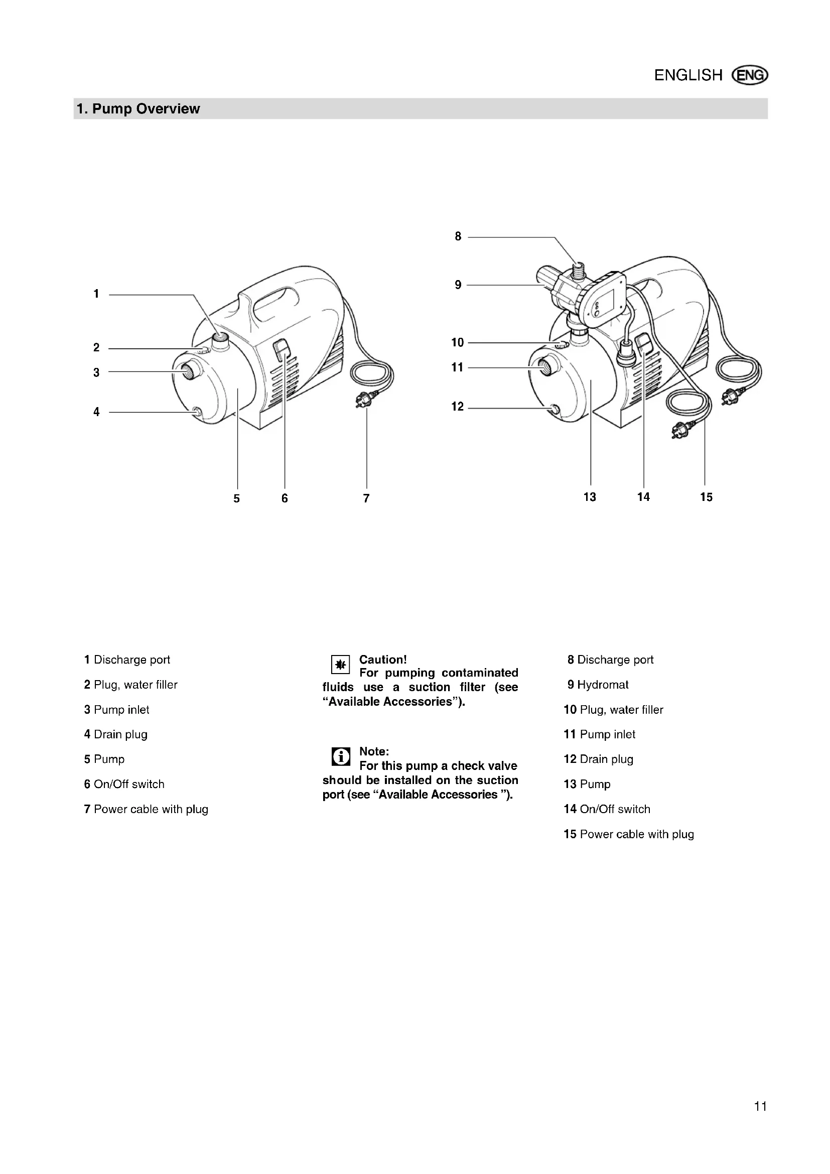
1 Discharge port
2 Plug, water filler
3 Pump inlet
4 Drain plug
5 Pump
6 On/Off switch
7 Power cable with plug
Caution! For pumping contaminated fluids use a suction filter (see "Available Accessories").
Note: For this pump a check valve should be installed on the suction port (see "Available Accessories").
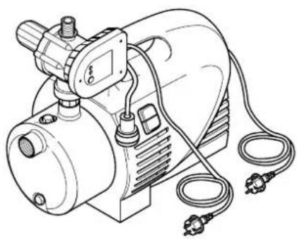
8 Discharge port
9 Hydromat
10 Plug, water filler
11 Pump inlet
12 Drain plug
13 Pump
14 On/Off switch
15 Power cable with plug
Table of Contents
-
Pump Overview ......11
-
Please Read First!......12
-
Range of Application and Pumping Media....12
-
Safety ......12
4.1 Specified Conditions of Use .....12
4.2 General Safety Instructions.....12
- Prior to Operation ......13
5.1 Installing the Hydromat (HWA only)....13
5.2 Installation....13
5.3 Connecting the Suction Line .....13
5.4 Discharge Port 13
5.5 Connection to AC Power......14
5.6 Filling the pump and priming .....14
- Operation ....14
6.1 Commissioning....14
6.2 Starting a pump with Hydromat (HWA)....14
- Care and Maintenance.....15
7.1 Danger of Ffreezing 15
7.2 Pump Dismounting and Storing....15
- Trouble Shooting .....15
8.1 Locating the Fault....15
-
Repairs......15
-
Environmental Protection .....15
-
Available Accessories .....15/62
-
Technical Specifications .....16
2. Please Read First!
These operating instructions have been written to make it easier for you, the operator, to learn how to operate this pump and to do so safely. These instructions should be used as follows:
- Read these instructions before use. When reading these instructions, pay special attention to all safety instructions.
- These operating instructions are intended for people with basic technical knowledge regarding the operation of a pump like this or similar pumps. Inexperienced persons are advised to seek competent advise from an experienced person before operating this pump.
- Keep all documents supplied with the pump for future reference. Retain proof of purchase for possible warranty claims.
- This pump must not be sold or lent to someone else without being accompanied by these operating instructions and all other machine documents supplied with the pump.
– The manufacturer assumes no liability for any damage resulting from the
non-observance of any operating or safety instructions given in this manual.
The information in these instructions is denoted as under:

Danger!
Risk of personal injury or damage to the environment.
Risk of electric shock!
Risk of personal injury by electric shock.

Caution!
Risk of material damage

Note:
Additional information.
– Numbers in illustrations (1, 2, 3, ...)
– indicate component parts;
- are consecutively numbered;
– refer to the corresponding numbers in brackets (1), (2), (3) ... in the neighbouring text.
- Instructions to be carried out in sequence are numbered.
- Instructions which can be carried out in any sequence are preceded by a bullet (•).
– Listing are preceded by a dash (−).
3. Range of Application and Pumping Media
This pump is intended for pumping clear water in domestic applications, such as
- irrigation,
- well, rain and service water pumping,
- draining of pools, garden ponds and water tanks.
The max. permissible temperature of the pumped medium is 35^ C.
4. Safety
4.1 Specified Conditions of Use
This pump must not be used to supply drinking water or for pumping foodstuff.
Explosive, flammable, aggressive fluids or substances detrimental to health as well as salt water must not be pumped.
This pump is not suitable for commercial or industrial use.
Modification of the pump or use of parts not approved by the manufacturer is not permitted.
Any other used is not as specified. The manufacturer assumes no liability for damage caused by unspecified use.
4.2 General Safety Instructions
Children, juveniles and persons not familiar with the instructions are not permitted to operate the pump.
When used at swimming pools and garden ponds and their range of protection the regulations according to DIN VDE 0100 -702, -738 are to be observed.
When used as domestic water supply all applicable local regulations pertaining to water supply and waste water disposal, plus DIN 1988 (where applicable) have to be observed.
The following residual risks do principally exist when operating pumps and pressure vessels and can not be fully eliminated – even by employing safety devices.

Hazard generated by ambient conditions!
- Do not expose to rain. Do not operate in damp or wet environment.
- Do not use the pump in hazardous locations or near inflammable liquids and gases!

Danger: Hot water!
If the shut-off pressure of the pressure switch cannot be reached due to poor pressure conditions or a defective pressure switch the water can heat up within the pump as a result of internal circulation.
Through this the pump and the connection lines can become damaged or leaky, allowing hot water to escape. Danger of scalding!
- Do not operate the pump against a closed pressure line for longer than 5 minutes.
- Unplug the pump and allow to cool. A specialist must check the system to make sure it is in perfect working order before it can be used again.

Danger! Risk of electric shock!
- Do not direct water jet directly against the pump or other electrical parts! Risk of fatal electric shock!
- Do not touch the plug with wet hands! To unplug always pull on the plug, not the power cable.
- The earthed outlet or the plug connection to an extension cable must be located in an area safe against flooding.
- Use only extension cables of sufficient lead cross section (see
"Technical Specifications"). Completely unroll cable reels.
- Do not buckle, squeeze, drag or drive over power cable and extension cables; protect from sharp edges.
- Place extension cable so that it can not get into the fluid to be pumped.
- Unplug:
– prior to all servicing;
- when persons are in the swimming pool or garden pond.

Danger by pump failures!
- If you notice transport damage while unpacking, notify your supplier immediately. Do not operate the pump!
- Before each use check the pump, especially the power cable and plug for possible damage. Risk of fatal electric shock!
- A damaged pump must be work-manlike repaired before it can be used again.
- Do not attempt to repair the pump yourself! Only trained specialists are permitted to service or repair pumps or pressure vessels.

Caution!
To avoid water damage, e.g.
flooded rooms, caused by pump malfunctions or defects:
• provide for suitable safety measures such as the following:
- alarm or
– collection tank with monitoring.
The manufacturer is not liable for any damage caused by:
– improper use of the pump;
– overloading of the pump through continuous operation;
– failure to operate and store the pump in a frost-free environment;
- unauthorised modification of the pump (repairs to electrical equipment may only be carried out by qualified electricians!);
- use of spare parts which have not been tested and approved by the manufacturer; or
– use of unsuitable installation materials (fittings, connection lines etc.).
Suitable installation materials:
– pressure-resistant(min. 10 bar)
- heat-resistant (min. 100°C).
5. Prior to Operation
The pump is easily assembled and connected.
If in doubt, contact your specialist supplier or a qualified electrician.
5.1 Installing the Hydromat (HWA only)

Note:
Before initial operation the Hydromat must be installed (illustration according to version).
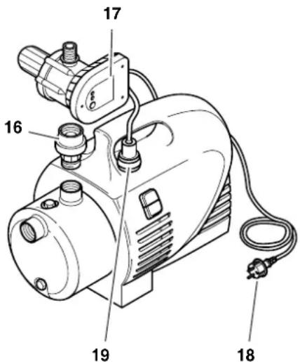
- Check to see that the pump is turned off and the power cord plug (18) is unplugged.
- Turn adaptor (16) onto the discharge port of the pump.
- Place Hydromat (17) on the adaptor and secure with the union nut.
- Adjust Hydromat position so that the control panel is easily accessible.
- Plug power cord plug of pump (18) in the Hydromat's cable socket (19).
5.2 Installation
- The pump must be placed on a plane and level surface, suitable of bearing the weight of the pump fully filled with water.
- To avoid vibrations the pump should be placed on an elastic base.
- The installation location should be well vented and protected from atmospheric exposure.
- When operated at garden ponds and pools the pump must be set up safe against flooding and safeguarded against falling into the water. Any additional legal requirements are to be observed.
5.3 Connecting the Suction Line

Note:
Possibly further accessories may be required for connection (see "Available Accessories").

Caution!
The suction line needs to be installed in such manner that it does not exert mechanical force or distortion to the pump.

Caution!
When pumping contaminated fluids install a suction strainer to protect the pump from sand and dirt.

Note:
A check valve is recommended to prevent water backflow when the pump is turned off.
- All screw fittings must be sealed with thread sealing tape; leaks cause the priming of air, which reduces or completely prevents the priming of water.
- The suction line should have an inner diameter of 1" (25 mm) minimum and must be kink, pressure, and vacuum resistant.
- Keep suction line as short as practical, as with increasing length the pump capacity is reduced.
- The suction line should ascend towards the pump to prevent air locks.
- A sufficient water supply must be ensured, the foot valve at the end of the suction line must be submerged in water at all times.
5.4 Discharge Port

Note:
Possibly further accessories may be required for connection (see "Available Accessories").

Caution!
The discharge (or pressure) line needs to be installed in such manner that it does not exert mechanical force or distortion to the pump.
- All screw fittings should be sealed with thread sealing tape to prevent leakage.
- All parts of the pressure line must be resistant to internal pressure.
- All parts of the pressure line must be installed in a workmanlike manner.

Danger!
Improper installation and use of parts not resistant to internal pressure can cause the pressure line to break during operation. Risk of personal injury by liquid spurting from the line under high pressure!
5.5 Connection to AC Power
Danger! Risk of electric shock! Do not operate the pump in wet environment and only under the following conditions:
- Connect only to an earthed outlet that is properly installed, earthed and tested.
- Mains voltage and fuse protection must correspond with the requirement stated in the "Technical Specifications".
- When operated at pools, garden ponds and similar locations, the pump must be protected by a residual current operated device (RCD, 30 mA) (DIN VDE 0100 -702, -738 or equivalent applicable local regulations).
We recommend the use of RCD's as a general precaution for personal protection.
- When operating the pump outdoors the electrical connections must be splash-proof; the connections must not be placed into water.
- Use only extension cables of sufficient lead cross section (see "Technical Specifications"). Completely unroll cable reels.
5.6 Filling the pump and priming

Caution!
After installation, loss of water or priming of air the pump needs to be filled with water. Starting the pump without water causes damage!

Note:
The suction line does not need to be filled, the pump is self-priming. However, depending on length and diameter of the suction line it may take some time until pressure has built up.
- Remove the water filler plug, complete with gasket.
- Slowly pour in clear water, until the pump is filled.
- To reduce the time needed for priming you can also fill the suction line.
- Replace the water filler plug, complete with gasket.
- Open pressure line (open tap or spray nozzle) for any air to escape during priming.
- Start pump (see "Operation").
- Turn pump OFF when water runs out steadily.
6. Operation
Pump and suction line must be connected and filled (see "Prior to Operation").

Caution!
The pump must not run dry.
Ensure there is always sufficient pumping medium (water) available.
- If the motor does not start, no pressure is built up or similar effects are evident, switch the pump OFF – and try to resolve the fault (see "Trouble Shooting").
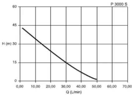
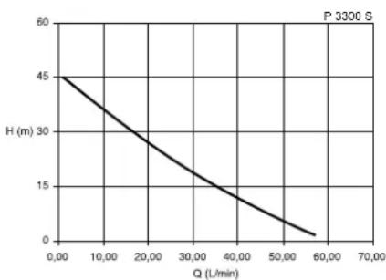
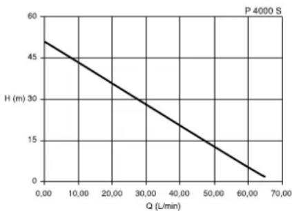
Pump characteristic curve
The pump characteristic curve shows which pump capacity is possible in dependence on the delivery head.
line
P 3000 S | Q (L/min) | H (m) | | :--- | :--- | | 0.00 | 45 | | 10.00 | 35 | | 20.00 | 25 | | 30.00 | 15 | | 40.00 | 10 | | 50.00 | 5 | The chart displays a single descending line from left to right, indicating that as flow rate increases, height decreases proportionally. The label 'P 3000 S' appears in the top-right corner.(Pump characteristic curve for 0.5 m suction head and 1" suction hose.)
line
| Q (L/min) | H (m) | | --------- | ----- | | 0.00 | 45.0 | | 10.00 | 35.0 | | 20.00 | 25.0 | | 30.00 | 15.0 | | 40.00 | 10.0 | | 50.00 | 5.0 | | 60.00 | 0.0 |(Pump characteristic curve for 0.5 m suction head and 1" suction hose.)
line
P 4000 S | Q (L/min) | H (m) | | :--- | :--- | | 0.00 | 57 | | 10.00 | 45 | | 20.00 | 33 | | 30.00 | 21 | | 40.00 | 10 | | 50.00 | 6 | | 60.00 | 2 | | 70.00 | 0 |(Pump characteristic curve for 0.5 m suction head and 1" suction hose.)
6.1 Commissioning

Note:
The pump runs as long as the ON/OFF switch is switched ON.
- Plug power cable in.
- Switch pump on with the ON/OFF switch.
- Open pressure line (open tap or spray nozzle).
- Check to see that the water comes out!

Caution!
With a closed pressure line do not let pump run for more then 10 minutes, otherwise there could be damage by the water overheating in the pump.
6.2 Starting a pump with Hydromat (HWA)

Note:
A pump with installed Hydromat is operational as long as the ON/OFF switch is turned ON.
The Hydromat
- starts the pump when water is required (when opening the discharge line the water pressure falls off to below the cut-in pressure);
- turns the pump off approx. 10 seconds after closing the discharge line (water pressure increases in the closed discharge line);
- turns the pump off to prevent dry running when no water is pumped (air in suction line).
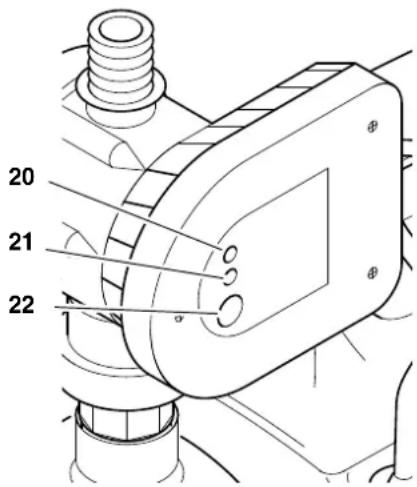
20 Power indicator (green)
21 Pump indicator (white)
22 Reset button
- Plug power cable in.
- Check to see that the power indicator (20) is illuminated.
- Open discharge line.
- Press the reset button (22). The pump will start running.
- If there is no water pumped after approx. 10 seconds the Hydromat will turn off. Then press and hold the reset button (22) until water emerges.
- If no water emerges after approx. 3 minutes, check the suction line.
7. Care and Maintenance

Danger! Prior to all servicing:
- Turn OFF.
- Unplug.
- Ensure that pressure is relieved from the pump and connected accessories.
Service and repair work other than described here must be left to qualified specialists.
7.1 Danger of Ffreezing
Caution! Frost damages the pump and accessories, as both always contain water!
- When there is danger of freezing, dismount the pump and accessories and store at a frost-free location (see below).
7.2 Pump Dismounting and Storing
- Turn pump OFF and unplug.
- Open pressure line (open tap or spray nozzle) and drain water completely.
- Drain pump completely; to do so remove the drain plug from the pump
- Disconnect suction and pressure lines from the pump.
- Store pump in a frost-free location (at least 5 °C).
8. Trouble Shooting

Danger! Prior to all servicing:
- Turn OFF.
- Unplug.
- Ensure that pressure is relieved from the pump and connected accessories.
8.1 Locating the Fault
Pump does not run:
- Pump not turned ON.
- Start pump at the ON/OFF switch.
- Hydromat has cut out.
- Press the reset button.
If no water is pumped after approx. 10 seconds, press and hold reset button until Water emerges.
- No mains voltage.
- Check cables, plug, outlet and mains fuse.
- Mains voltage too low.
- Use only extension cables with sufficient lead cross section (see "Technical Specifications").
- Motor overheated, motor protection relay tripped.
• After cooling off the pump will start again.
- Ensure sufficient ventilation, keep vent slots clear.
- Observe max. temperature of the pumped medium.
- Motor hums but does not start. - With the motor turned OFF, put screwdriver or similar through the fan cover's ventilation slots and turn the fan.
– Pump blocked or out of order.
• Disassemble pump and clean.
- Clean diffusor, replace if necessary.
- Clean impeller, replace if necessary.
Pump does not prime correctly or runs very noisily:
- Lack of water.
- Ensure there is a sufficient water supply.
– Suction line leaky. - Seal suction line, tighten screw fittings.
– Suction head too high. - Observe max. suction head.
• Install check valve, fill suction line with water.
- Suction strainer (optional accessory) blocked.
- Clean, replace if necessary.
- Check valve (optional accessory) blocked.
- Clean, replace if necessary.
- Water leaks between motor and pump, Ducone seal worn.
- Replace Ducone seal.
– Pump blocked or out of order.
- see above.
Pressure too low:
- Suction line leaky or too much suction head.
- see above.
– Pump blocked or out of order.
- see above.
9. Repairs
Danger! Repairs to electric tools must only be carried out by a qualified electrician!
Electric tools in need of repair can be sent to an authorized service center in your country. See spare parts list for address.
Please attach a description of the fault to the electric tool.
10. Environmental Protection
The packaging material of the pump is 100 % recyclable.
Worn out power tools and accessories contain considerable amounts of valuable raw and plastic materials, which can be recycled.
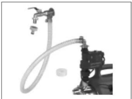
11. Available Accessories
For this pump the following accessories are available from your dealer.
Note: Illustrations and stock numbers are shown at the end of this manual.
A Pump Installation Package, (MSS 310 – HWA/P), complete with double nipple, check valve, filter short, washable filter cartridge, spiral hose assembly 1 m, thread sealing tape.
B Pump Installation Package, (MSS 380 - HWW), complete with double nipple, check valve, filter short, washable filter cartridge, spiral hose assembly 1m , thread sealing tape.
C Pump Installation Package, (MSS 200 - HWW/P), complete with double nipple, check valve, filter short, washable filter cartridge, spiral hose assembly 1 m, thread sealing tape.
D Pump Installation Package,
(MSS 1000 – HWA), complete with double nipple, check valve, filter short, washable filter cartridge, spiral hose assembly 1 m, thread sealing tape.
E F ilter (for garden pumps), 1" connection, short, c/w washable synthetic material filter cartridge.
F Filter (for domestic water systems), 1" connection, short, c/w washable synthetic material filter cartridge.
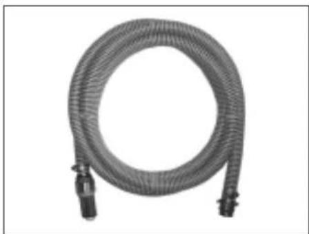
G Spiral Suction Hose 1" (standard) 1) 4 m, c/w quick release screw fitting and strainer with foot valve;
2) 7 m, c/w quick release screw fitting and strainer with foot valve;
H Spiral Suction Hose 1" (professional)
1) 1.5 m, both ends with quick release screw fitting;
2) 4 m, c/w quick release screw fitting and strainer with foot valve;
3) 7 m, c/w quick release screw fitting and strainer with foot valve;
I Rei nforced Hose 500 mm
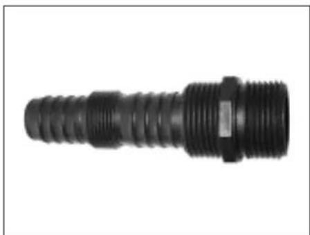
J Multi-ad apter 1" ideal for connecting to pumps with 1" AG connector (AG=male thread, IG=female thread)
K Hydrostop, for automatic stopping when there is a lack of water, prevents the pump from running dry.
L Dry-running Stop Switch, with 10 m cable, keeps the pump
from running dry when pumping from tank, pool, etc.
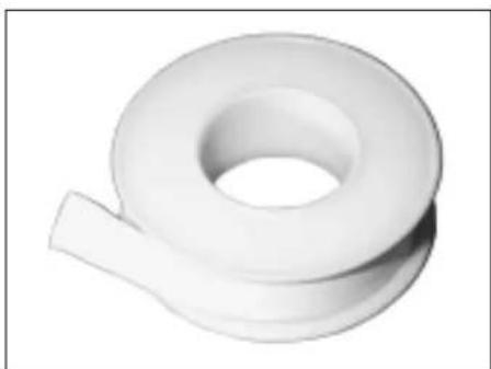
M Th read Sealing Tape, 12 m roll.
N Wa shable Filter Cartridge, short, for mechanical pre-filtering of sand, reusable.
O Wa shable Filter Cartridge, long, for mechanical pre-filtering of sand, reusable.
- Technical Specifications
| P 3300 SHWA 3300 S | P 4000 SHWA 4000 S | ||
| Mains voltage V 230~1 | 50 | ||
| Frequency Hz | |||
| Rated output W 1100 1300 | |||
| Rated current | A | 4.5 | 4.5 |
| Fuse protection min. (time-lag or B-type circuit breaker) | A | 10 | 10 |
| Running capacitor | μF | 16 | 20 |
| Rated speed | min^-1 | 2800 2800 | |
| Pump capacity max. | l/h | 3300 | 4000 |
| Delivery head max. | m | 45 | 48 |
| Delivery pressure max. | bar | 4,5 | 4.8 |
| Max. suction head | m | 8 | 8 |
| Temperature of the primed medium max. | °C | 35 | 35 |
| Ambient temperature | °C | 5 ... 40 | 5 ... 40 |
| Degree of protection | IP | X4 | X4 |
| Protection class | I | I | |
| Insulation class | B | B | |
| Materials | |||
| Pump casing | Stainless steel | Stainless steel | |
| Pump shaft | Stainless steel | Stainless steel | |
| Impeller | Noryl | Noryl | |
| Connections | |||
| Intake port (female thread) | 1" | 1" | |
| Discharge port (male thread) | 1" | 1" | |
| Hydromat | |||
| Cut-in pressure approx. | bar | 1.5 | 1.5 |
| Dimensions (without connections) | |||
| Length | mm | 470 / 470 | 470 / 470 |
| Width | mm | 250 / 250 | 250 / 250 |
| Height | mm | 300 / 415 | 300 / 415 |
| Weights | |||
| Dry weight | kg | 10.2 / 11.5 | 10.5 / 11.8 |
| Weight filled with water | kg | 11.7 / 13 | 12.0 / 13.3 |
| Noise emission values (at max. pressure) | |||
| Sound power level L_WAm | dB (A) | 83 | 86 |
| Sound pressure level L_WAd | dB (A) | 90 | 89 |
| Max. length of extension cable | |||
| at 3 x 1.0 mm^2 lead cross-section | m | 30 | |
| at 3 x 1.5 mm^2 lead cross-section | m | 50 | |
line
| Q (L/min) | H (m) | | --------- | ----- | | 0.00 | 50 | | 70.00 | 0 |E Fi Iter (havepumper),
Adapter 1", kort,
komplet med en afvaskelig plast-filterindsats.
F Fi Iter (vandpumper til hus),
Adapter 1", lang,
komplet med vaskelig plast-filte-rindsats.
G Spira Islange 1" (standard)
1) 4 m, komplet med snaplåse og sugekurv med bundventil;
2) 7 m, komplet med snaplåse og sugekurv med bundventil;
H Spira Islange 1" (profi)
J Universaladapter 1"
ideel til tilslutning til pumpe med 1"
IG-adapter
natural_image
Close-up of a mechanical device with a cylindrical housing and attached nozzle, accompanied by a small circular component (no visible text or symbols)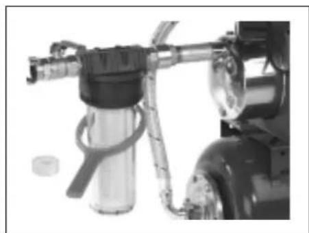
natural_image
Close-up of a spray gun assembly with hoses and a cylindrical container (no visible text or symbols)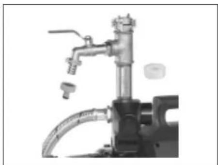
natural_image
Industrial piping system with valve and tubing (no visible text or symbols)A 090 306 1260 B 090 306 1278 C 090 306 1251
natural_image
Industrial equipment setup with a coiled hose and valve (no visible text or symbols)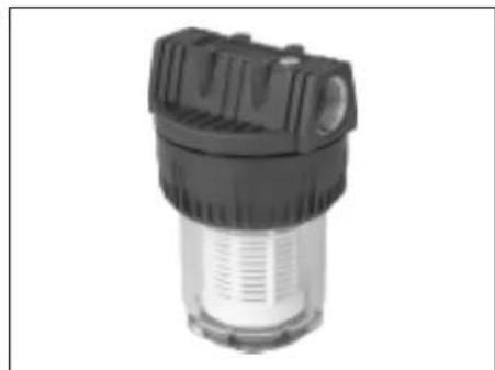
natural_image
Close-up of a black and white industrial filter component (no visible text or symbols)
natural_image
Exterior view of a cylindrical water filter or separator component (no text or symbols visible)D 090 306 1243 E 090 305 0314 F 090 305 0306
natural_image
Coiled industrial hose with flanged ends and connectors (no text or symbols visible)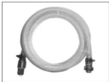
natural_image
Coiled transparent hose with connectors, no visible text or symbols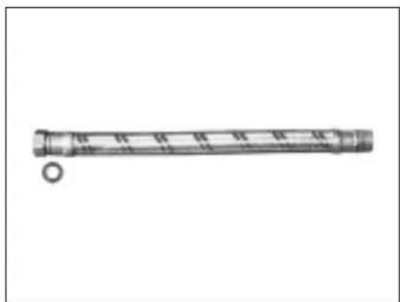
natural_image
Simple line drawing of a cylindrical object with a small circular end, no text or symbols present.1090 306 1340
G 1) 090 306 1227
2) 090 306 1235
H 1) 090 306 1197
2) 090 306 1100
3) 090 306 1219
natural_image
Black threaded connector with flanged ends (no text or symbols visible)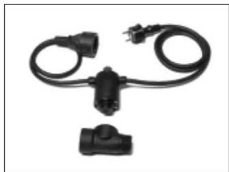
natural_image
Black electrical plug connectors with wires, no visible text or symbols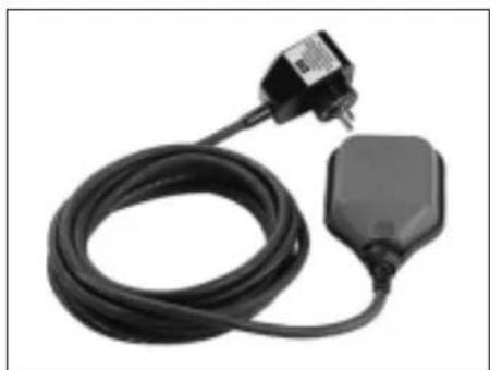
natural_image
Coiled black electrical plug with a small terminal block attached (no visible text or symbols)J 090 301 8410 K 090 305 2597 L 090 302 8521
natural_image
White plastic roller or tape component with a flat blade (no text or symbols visible)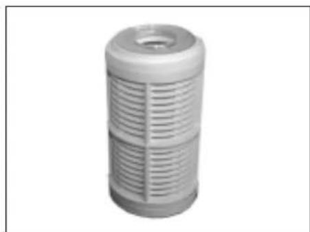
natural_image
3D rendering of a cylindrical mechanical component with ribbed internal structure (no text or symbols visible)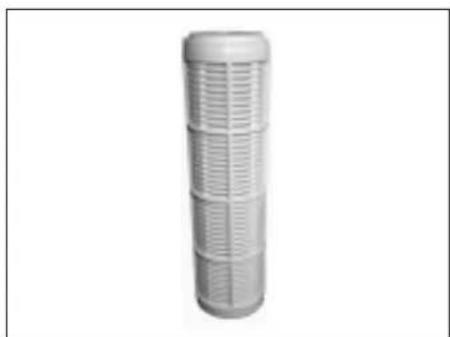
natural_image
3D rendered image of a cylindrical mechanical component with grid pattern (no text or symbols)M 090 102 6319 N 090 302 8440 O 090 302 8360


- DE EN
- NL
- Table of Contents
- Please Read First!
- Range of Application and Pumping Media
- Safety
- Specified Conditions of Use
- General Safety Instructions
- Hazard generated by ambient conditions!
- Danger: Hot water!
- Danger! Risk of electric shock!
- Danger by pump failures!
- Caution!
- flooded rooms, caused by pump malfunctions or defects:
- Prior to Operation
- Installing the Hydromat (HWA only)
- Note:
- Installation
- Connecting the Suction Line
- Discharge Port
- Danger!
- Connection to AC Power
- Filling the pump and priming
- Operation
- Pump characteristic curve
- Commissioning
- Starting a pump with Hydromat (HWA)
- The Hydromat
- Care and Maintenance
- Danger of Ffreezing
- Pump Dismounting and Storing
- Trouble Shooting
- Locating the Fault
- Pump does not prime correctly or runs very noisily:
- Pressure too low:
- Repairs
- Environmental Protection
- Available Accessories
Brand : METABO
Model : HWA 4000 S
Category : Pump