DFT024FMZ - Screwdriver MAKITA - Free user manual and instructions
Find the device manual for free DFT024FMZ MAKITA in PDF.

User questions about DFT024FMZ MAKITA
0 question about this device. Answer the ones you know or ask your own.
Ask a new question about this device
Download the instructions for your Screwdriver in PDF format for free! Find your manual DFT024FMZ - MAKITA and take your electronic device back in hand. On this page are published all the documents necessary for the use of your device. DFT024FMZ by MAKITA.
USER MANUAL DFT024FMZ MAKITA
Due to our continuing program of research and development, the specifications herein are subject to change without notice.
- Specifications may differ from country to country.
The weight may differ depending on the attachment(s), including the battery cartridge. The lightest and heaviest combination, according to EPTA-Procedure 01/2014, are shown in the table.
Applicable battery cartridge and charger
| Battery cartridge | BL1815N / BL1820B / BL1830B / BL1840B / BL1850B / BL1860B |
| Charger | DC18RC / DC18RD / DC18RE / DC18SD / DC18SE / DC18SF / DC18SH |
- Some of the battery cartridges and chargers listed above may not be available depending on your region of residence.

WARNING: Only use the battery cartridges and chargers listed above. Use of any other battery cartridges and chargers may cause injury and/or fire.
Intended use
The tool is intended for screw driving in wood, metal and plastic.
Noise
The typical A-weighted noise level determined according to EN62841-2-2:
Model DFT024F
Sound pressure level (L_pA):71 dB (A) Uncertainty (K):3 dB(A)
Model DFT025F
Sound pressure level (L_pA):71 dB (A) Uncertainty (K):3 dB(A)
Model DFT060F
Sound pressure level (L_pA):72dB(A) Uncertainty (K) : 3 dB(A)
The noise level under working may exceed 80 dB (A).
NOTE: The declared noise emission value(s) has been measured in accordance with a standard test method and may be used for comparing one tool with another.
NOTE: The declared noise emission value(s) may also be used in a preliminary assessment of exposure.

WARNING: Wear ear protection.

WARNING: The noise emission during actual use of the power tool can differ from the declared values) depending on the ways in which the tool is used, especially what kind of workpiece is processed.

WARNING: Be sure to identify safety measures to protect the operator that are based on an estimation of exposure in the actual conditions of use (take an account of all parts of the operating cycle such as the times when the tool is switched off and when it is running idle in addition to the trigger time).
Vibration
The vibration total value (tri-axial vector sum) determined according to EN62841-2-2:
Model DFT024F
Work mode: screwdriving without impact Vibration emission (a_n):2.5m / s^2 or less Uncertainty (K) 1.5m / s^2
Model DFT025F
Work mode: screwdriving without impact Vibration emission (a_n):2.5m / s^2 or less Uncertainty (K) 1.5m / s^2
Model DFT060F
Work mode: screwdriving without impact Vibration emission (a_n):2.5m / s^2 or less Uncertainty (K) 1.5m / s^2
NOTE: The declared vibration total value(s) has been measured in accordance with a standard test method and may be used for comparing one tool with another.
NOTE: The declared vibration total value(s) may also be used in a preliminary assessment of exposure.
WARNING: The vibration emission during actual use of the power tool can differ from the declared value(s) depending on the ways in which the tool is used especially what kind of workpiece is processed.
WARNING: Be sure to identify safety measures to protect the operator that are based on an estimation of exposure in the actual conditions of use (taking account of all parts of the operating cycle such as the times when the tool is switched off and when it is running idle in addition to the trigger time).
Declarations of Conformity
For European countries only
The Declarations of conformity are included in Annex A to this instruction manual.
SAFETYWARNINGS
General power tool safety warnings
WARNING: Read all safety warnings, instructions, illustrations and specifications provided with this power tool. Failure to follow all instructions listed below may result in electric shock, fire and/or serious injury.
Save all warnings and instructions for future reference.
The term "power tool" in the warnings refers to your mains-operated (corded) power tool or battery-operated (cordless) power tool.
Cordless screwdriver safety warnings
- Hold the power tool by insulated gripping surfaces, when performing an operation where the fastener may contact hidden wiring. Fasteners contacting a "live" wire may make exposed metal parts of the power tool "live" and could give the operator an electric shock.
- Always be sure you have a firm footing. Be sure no one is below when using the tool in high locations.
- Hold the tool firmly.
- Keep hands away from rotating parts.
- Do not touch the bit or the workpiece immediately after operation; they may be extremely hot and could burn your skin.
-
Always secure workpiece in a vise or similar hold-down device.
-
Make sure there are no electrical cables, water pipes, gas pipes etc. that could cause a hazard if damaged by use of the tool.
SAVE THESE INSTRUCTIONS.
WARNING: DO NOT let comfort or familiarity with product (gained from repeated use) replace strict adherence to safety rules for the subject product.
MISUSE or failure to follow the safety rules stated in this instruction manual may cause serious personal injury.
Important safety instructions for battery cartridge
- Before using battery cartridge, read all instructions and cautionary markings on (1) battery charger, (2) battery, and (3) product using battery.
- Do not disassemble or tamper with the battery cartridge. It may result in a fire, excessive heat, or explosion.
- If operating time has become excessively shorter, stop operating immediately. It may result in a risk of overheating, possible burns and even an explosion.
-
If electrolyte gets into your eyes, rinse them out with clear water and seek medical attention right away. It may result in loss of your eyesight.
-
Do not short the battery cartridge:
(1) Do not touch the terminals with any conductive material.
(2) Avoid storing battery cartridge in a container with other metal objects such as nails, coins, etc.
(3) Do not expose battery cartridge to water or rain. A battery short can cause a large current flow, overheating, possible burns and even a breakdown.
- Do not store and use the tool and battery cartridge in locations where the temperature may reach or exceed 50^ (122^) .
- Do not incinerate the battery cartridge even if it is severely damaged or is completely worn out. The battery cartridge can explode in a fire.
- Do not nail, cut, crush, throw, drop the battery cartridge, or hit against a hard object to the battery cartridge. Such conduct may result in a fire, excessive heat, or explosion.
- Do not use a damaged battery.
-
The contained lithium-ion batteries are subject to the Dangerous Goods Legislation requirements. For commercial transports e.g. by third parties, forwarding agents, special requirement on packaging and labeling must be observed. For preparation of the item being shipped, consulting an expert for hazardous material is required. Please also observe possibly more detailed national regulations. Tape or mask off open contacts and pack up the battery in such a manner that it cannot move around in the packaging.
-
When disposing the battery cartridge, remove it from the tool and dispose of it in a safe place. Follow your local regulations relating to disposal of battery.
- Use the batteries only with the products specified by Makita. Installing the batteries to non-compliant products may result in a fire, excessive heat, explosion, or leak of electrolyte.
- If the tool is not used for a long period of time, the battery must be removed from the tool.
- During and after use, the battery cartridge may take on heat which can cause burns or low temperature burns. Pay attention to the handling of hot battery cartridges.
- Do not touch the terminal of the tool immediately after use as it may get hot enough to cause burns.
- Do not allow chips, dust, or soil stuck into the terminals, holes, and grooves of the battery cartridge. It may result in poor performance or breakdown of the tool or battery cartridge.
- Unless the tool supports the use near high-voltage electrical power lines, do not use the battery cartridge near high-voltage electrical power lines. It may result in a malfunction or breakdown of the tool or battery cartridge.
- Keep the battery away from children. SAVE THESE INSTRUCTIONS.
CAUTION: Only use genuine Makita batteries. Use of non-genuine Makita batteries, or batteries that have been altered, may result in the battery bursting causing fires, personal injury and damage. It will also void the Makita warranty for the Makita tool and charger.
Tips for maintaining maximum battery life
- Charge the battery cartridge before completely discharged. Always stop tool operation and charge the battery cartridge when you notice less tool power.
- Never recharge a fully charged battery cartridge. Overcharging shortens the battery service life.
- Charge the battery cartridge with room temperature at 10^ - 40^ (50°F - 104°F). Let a hot battery cartridge cool down before charging it.
- When not using the battery cartridge, remove it from the tool or the charger.
- Charge the battery cartridge if you do not use it for a long period (more than six months).
FUNCTIONAL DESCRIPTION
CAUTION: Always be sure that the tool is switched off and the battery cartridge is removed before adjusting or checking function on the tool.
Installing or removing battery cartridge
CAUTION: Always switch off the tool before installing or removing of the battery cartridge.
CAUTION: Hold the tool and the battery cartridge firmly when installing or removing battery cartridge. Failure to hold the tool and the battery cartridge firmly may cause them to slip off your hands and result in damage to the tool and battery cartridge and a personal injury.
Fig.1: 1. Red indicator 2. Button 3. Battery cartridge
To remove the battery cartridge, slide it from the tool while sliding the button on the front of the cartridge.
To install the battery cartridge, align the tongue on the battery cartridge with the groove in the housing and slip it into place. Insert it all the way until it locks in place with a little click. If you can see the red indicator as shown in the figure, it is not locked completely.
CAUTION: Always install the battery cartridge fully until the red indicator cannot be seen. If not, it may accidentally fall out of the tool, causing injury to you or someone around you.
CAUTION: Do not install the battery cartridge forcibly. If the cartridge does not slide in easily, it is not being inserted correctly.
Indicating the remaining battery capacity
Only for battery cartridges with the indicator
Fig.2: 1. Indicator lamps 2. Check button
Press the check button on the battery cartridge to indicate the remaining battery capacity. The indicator lamps light up for a few seconds.
| Indicator lamps Remaining | capacity | ||
| Lighted Off | Blinking | ||
| 75% to 100% | |||
| 50% to 75% | |||
| 25% to 50% | |||
| 0% to 25% | |||
| Charge the battery. | |||
| The battery may have malfunctioned. | |||
NOTE: Depending on the conditions of use and the ambient temperature, the indication may differ slightly from the actual capacity.
NOTE: The first (far left) indicator lamp will blink when the battery protection system works.
Tool / battery protection system
The tool is equipped with a tool/battery protection system. This system automatically cuts off power to the motor to extend tool and battery life. The tool will automatically stop during operation if the tool or battery is placed under one of the following conditions:
Overload protection
When the tool/battery is operated in a manner that causes it to draw an abnormally high current, the tool stops automatically. In this situation, turn the tool off and stop the application that caused the tool to become overloaded. Then turn the tool on to restart.
Overheat protection
When the tool/battery is overheated, the tool stops automatically. In this situation, let the tool/battery cool before turning the tool on again.
Overdischarge protection
When the battery capacity is not enough, the tool stops automatically. In this case, remove the battery from the tool and charge the battery.
Switch action
WARNING: Before installing the battery cartridge into the tool, always check to see that the switch trigger actuates properly and returns to the "OFF" position when released.
To start the tool, simply pull the switch trigger. Release the switch trigger to stop.
Fig.3: 1. Switch trigger
NOTE: For approximately one second after fastening, the tool does not work even with the switch pulled.
Lighting up the front lamp
Fig.4: 1. Lamp
CAUTION: Do not look in the light or see the source of light directly.
Pull the switch trigger to light up the lamp. The lamp keeps on lighting while the switch trigger is being pulled. The lamp goes out approximately 10 seconds after releasing the switch trigger.
NOTE: Use a dry cloth to wipe the dirt off the lens of the lamp. Be careful not to scratch the lens of lamp, or it may lower the illumination.
Reversing switch action
Fig.5: 1. Reversing switch lever
CAUTION: Always check the direction of rotation before operation.
CAUTION: Use the reversing switch only after the tool comes to a complete stop. Changing the direction of rotation before the tool stops may damage the tool.
CAUTION: When not operating the tool, always set the reversing switch lever to the neutral position.
This tool has a reversing switch to change the direction of rotation. Depress the reversing switch lever from the A side for clockwise rotation or from the B side for counterclockwise rotation.
When the reversing switch lever is in the neutral position, the switch trigger cannot be pulled.
Fig.6: 1. LED indicator
LED indicator / Beeper on the tool shows the following functions.
| Function Status | of the tool Status of the LED | indicator/beeper Action to be taken | ||
| LED indicator Beeper | ||||
| Check of the LED indicator, light and beeper operation | When the battery car- tridge is installed, the tool checks for its LED indi- cator, light and beeper. | Lights up first in green, next red.(And then the light comes on.) | A series of very short beeps | - |
| Detection of switch trigger operation when installing battery | When the battery car- tridge is installed with the switch trigger pulled, the tool stops to avoid unintentional start. | Blinks in red and green alternatively. | A series of short beeps Re- lase the switch trigger. | |
| Auto-stop with fastening completion | The tool setting has been achieved and the tool has stopped. | Lights up in green for approximately one second. | - | - |
| Alarm against insufficient fastening | The tool has not completed the tool setting because the switch trigger has released before reaching the set values. Otherwise, the settings of "Failure Criteria for Phase" has been achieved. | Lights up in red. A long beep Retighten the screw. | ||
| Intermission between the phases | The tool is in the inter- mitting period configured by the setting of "Shift to the next Phase". | Lights up or blinks in green (depending on settings) | - | - |
| Double-hitting detection | When the operator starts to re-fasten an already-fas- tened screw, the tool detect it and stops. | Lights up in red. A long beep - | ||
| Alarm for low battery capacity | The battery power became low and it is time to replace the battery cartridge. | Blinks in red slowly. A ser- es of long beeps Replace the battery with fully charged one. | ||
| Auto-stop with low remaining battery capacity | The battery power is almost used up and the tool stopped. | Lights up in red. A long beep Replace the battery with fully charged one. | ||
| Anti-reset of controller The battery voltage dropped abnormally for some reason, and the tool stopped. | Blinks in red and green alternatively. | A series of short beeps Replace the battery with fully charged one. | ||
| Overheat protection The motor or the control- ler heated up abnormally and the tool stopped. | Blinks in red quickly. A ser- es of short beeps Remove the battery car- tridge immediately and cool the tool down. | |||
| Failure to detect heat of motor | The detection unit of the motor fails to detect the heat because the cord has broken or other reasons. | Blinks in red quickly. A ser- es of short beeps | Remove the battery cartridge and cool the tool down. If the indicator does not stop, ask your local Makita Service Center for repair. | |
| Motor failure detection | Motor failure has been detected. At this time, tool does not work. | Blinks in red and green alternatively. | A series of short beeps Ask your local Makita Service Center for repair. | |
| Maintenance alarm | A maintenance time has come according to your preset number of screws driven. | Blinks in yellow. | - | Reset the alarm with the application software. |
| Alarm for unavailable data communication (with the tool in connec- tion with PC) | Data cannot be exchanged between the tool and PC in spite of the connection. | Blinks in yellow. | - | Restart the application software and re-connect the USB cable. |
| Indication that data com- munication is available (with the tool in connec- tion with PC) | The tool is connected to PC and data communi- cation is available. | Blinks in green. | -- | |
Adjusting the fastening torque
When you wish to drive machine screws, hex bolts, etc. with the predetermined torque, adjust the fastening torque as follows.
- Open the change plate by hand so that you can see a hole.
Fig.7: 1. Change plate
- Pull the switch trigger and release it so that the adjust ring rotates and the hole becomes visible. And then remove the battery cartridge.
- Use an optional adjust grip to adjust the fastening torque. Insert the pin of the adjust grip into the hole in the front of the tool. And then, turn the adjust grip clockwise to set a greater fastening torque, and counterclockwise to set a smaller fastening torque.
Fig.8: 1. Adjust grip 2. Hole for adjust grip
- Insert the battery cartridge and be sure that a fastening torque has been set up by using a fastening torque tester.
- Close the change plate by hand securely.
Adjusting no-load speed and revolution angle etc.
You can adjust the no-load speed, number of turn, etc. of the tool with your computer. Install the application software in your computer and connect it to the tool with an USB cable.
Fig.9: 1. USB port 2. USB cover 3. USB cable
NOTICE: Make sure that the USB cover closed when fastening.
NOTE: Use the makita genuine USB cable to connect your computer to the tool. Refer to the section "SPECIFICATIONS".
NOTE: For the application software, please contact Makita sales representative.
ASSEMBLY
CAUTION: Always be sure that the tool is switched off and the battery cartridge is removed before carrying out any work on the tool.
Installing or removing driver bit/ socket bit
Fig.10
Use only driver bit/socket bit that has inserting portion shown in the figure. Do not use any other driver bit/ socket bit.
For tool with shallow driver bit hole
A=12mm
B=9mm
Use only these type of driver bit. Follow the procedure
- (Note) Bit-piece is not necessary.
For tool with deep driver bit hole
| A=17mm B=14mm | To install these types of driver bits, follow the procedure 1. |
| A=12mm B=9mm | To install these types of driver bits, follow the procedure 2. (Note) Bit-piece is necessary for installing the bit. |
Procedure 1
For tool without one-touch type sleeve
Fig.11: 1.Driver bit 2.Sleeve
To install the driver bit, pull the sleeve in the direction of the arrow and insert the driver bit into the sleeve as far as it will go.
Then release the sleeve to secure the driver bit.
For tool with one-touch type sleeve
To install the driver bit, insert the driver bit into the sleeve as far as it will go.
Procedure 2
In addition to Procedure 1, insert the bit-piece into the sleeve with its pointed end facing in.
Fig.12: 1. Driver bit 2. Bit-piece 3. Sleeve
To remove the driver bit, pull the sleeve in the direction of the arrow and pull the driver bit out.
NOTE: If the driver bit is not inserted deep enough into the sleeve, the sleeve will not return to its original position and the driver bit will not be secured. In this case, try re-inserting the bit according to the instructions above.
NOTE: When it is difficult to insert the driver bit, pull the sleeve and insert it into the sleeve as far as it will go.
NOTE: After inserting the driver bit, make sure that it is firmly secured. If it comes out, do not use it.
Installing hook
Optional accessory
The hook is useful to hang the tool. Install the hook to the holes on the tool body.
Fig.13: 1. Hook 2. Hole
OPERATION
Screwdriving operation
CAUTION: Make sure that the bit is inserted straight in the screw head, or the screw and/or bit may be damaged.
Place the point of the driver bit in the screw head and apply pressure to the tool. Then switch the tool on. When the clutch cuts in, the motor will stop automatically. Then release the switch trigger.
Fig.14
Limits of fastening capacity
Use the tool within the limits of fastening capacity. If you use the tool beyond the limits, the clutch does not work. And the tool cannot deliver enough fastening torque.
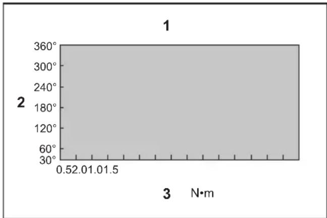
For model DFT024F / DFT025F
- Range of fastening capacity 2. Rotation angle
- Torque
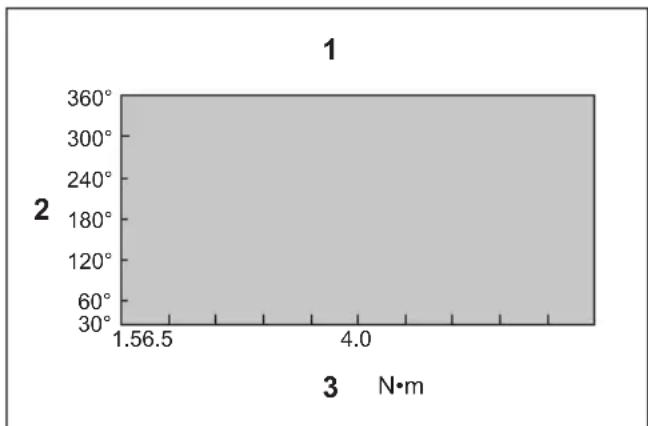
For model DFT060F
- Range of fastening capacity 2. Rotation angle
- Torque
NOTE: The rotation angle is the angle from the point that the bolt is tightened in 50% of desired torque to the point that the bolt is tightened in 100% torque.
NOTE: Use of a cold battery cartridge may give warning for battery capacity by LED indicator and beeper and stop the tool immediately, even if it is fully charged. In this case, the fastening capacity may be inferior to the specification on this manual.
MAINTENANCE
CAUTION: Always be sure that the tool is switched off and the battery cartridge is removed before attempting to perform inspection or maintenance.
NOTICE: Never use gasoline, benzine, thinner, alcohol or the like. Discoloration, deformation or cracks may result.
To maintain product SAFETY and RELIABILITY, repairs, any other maintenance or adjustment should be performed by Makita Authorized or Factory Service Centers, always using Makita replacement parts.
OPTIONAL ACCESSORIES
CAUTION: These accessories or attachments are recommended for use with your Makita tool specified in this manual. The use of any other accessories or attachments might present a risk of injury to persons. Only use accessory or attachment for its stated purpose.
If you need any assistance for more details regarding these accessories, ask your local Makita Service Center.
- Adjust grip
- Protector (Natural, Red, Blue, Yellow, Green)
USB cable - Hook
- Lock nut (Red, Blue, Yellow)
- Makita genuine battery and charger
NOTE: Some items in the list may be included in the tool package as standard accessories. They may differ from country to country.
SPECIFICATIONS
ACCESSIONS EN OPTION
WAARSCHUWING: Draag gehoorbescheming.
VEILIGHEIDSWAARSCHUWINGEN
OPTIONELE ACCESSOIRES
Móvo yia xwpe ts Eupwnns
Oi Anwoeicuupoppwocnpeiaaavovtai oTo Iapaptnma A oTo npov exyeipidio odnyiwv.
IPOEIAOIOIHSEI AΣΦAΛEIAΣ
Evikeoioeia yia to nEKTpiko epyaeeio
ANPOEIOHOH: AiaBaoTe 6AeTc TITPOEI-0toiOeIaOaAeiac, OByieC, EIKOVoyapnoeIC KAI TPOdiaypaoe tsou TApexovtai e auto to nEktpiko epyaio. H m npon oawv twv oywiiv TIO avaypavotai katwepw mtopei va kataanne i e NktpottAnjia, Tupkayia n/kai ooapop tpaumatio.
UαTe oεc TIG POeioToin-σεi KAI TIG OByεγia eλo-vtikn TapaTouπn.
Ttpoeiooieic, o opoc «nEeKpiKO epyaleio» avaepetai eNekptiko epyaiaou tropoooteiata nTv Kupia npoxn Nekptikou pEuutc (u EneKPTko Kaawio) n eNekptiko epyaiaou tropoooteiata ato mtaupia (xwpi nEeKptiko kaawio).
PpOeIodOIOInoEic aOpaAeiaC yia To aOpMaTo KaTaQaβiδi
Eik.11: 1.Mutn BiDomega2.Took
Tia va toTtooTeNToMuTn BiDwatoC, TpaBnTe To
TOOK TTPOc Tnv KATEUeuvon Tou Belaouc KAI EIAayayete Tn
muT NbiDwatoC OTo TOok MEXPI Tepua.
KATOIV, aPnoTE To Took YIA VA aOVaaiote Tn MuTn
BiDwatoC.
Ia epyaieioeXitwio tuou evoc ayyiyuatoC
Tia va totoeintoe Tn uTn BiowuatoC, BALTE Tn puTn
BldwatoC meo stiWvio expi Tepa.
Δiaδikασία 2
EKTOSI 1, EIOAYAYETO TEUAXIO uTNS WOT OAIUMPO TNC AKPO VA EIVAI OTPAPUEVO TPOs ta eo.
Eik.12: 1.Mutn biOwmuToC 2.Teuxo uTnc 3.Took
Tia va byaAETn mUTn BldwatoC, TpaBnETo TOOK TTPOc Tnv KATEuOuvon Tou BeAUc KAI TpaBnEe Tn MUTN BldwatoC TPOC Ta E\xw.
NAPATHPHSH: Av n μutn βidωpatoc δev exei εioa-χθεi apketa αθia έσα oTO TOOK, TOAK δEV θa ETIOPTpey iσntv apxikn tou έeON kai n μutn βidωpatoδev θa αφλiOTε. Σην πeipittwn autn, TPOOIIaθnote va εioayayete gava tny μutn σuφwva εTIC TAPATTAVW odnyieç.
NAPATHPHSH: Otav eivai duokoan n totoeTnAn TnsmuTnc BiowatoC,tpaBngTe to xitwio kai EiaayyETe tnmuTn meo aTo xitwio expi tepa.
NAPATHPHs: Apoou totooetnoeTe Tn uTn Bldwau- tos, BébaiwOeIe oT iEiva Ka a oopaiouevn. Av oomega , mV n Tn xpnoioutoioeTe.
ToTOnEeTnon yavTzou
Pnoaipetiko aesouap
O yavzoc xnpoiueui ia to kpeuaogau tou epyaieou. TOnoetnote to yavzo otic oTec oTo oWau Tou epyaieou.
Eik.13:1.Favrcs 2.Om
AEITOYPTIA
Aειουργία βιδώματος
A PPOOXH: Bebaowte oToTtoehtnate tn uTn aTeuEiaoc otny Kepaan Tng Biac. Diaopopeiká,muTpei va pokAnthe Znua ot n BiadnKai ot n utn.
TOnoTeTnTo akpo TnC mUTnc BiDomegaTc OTN KepaI n Tng Bida cai aoknoTE TIEON OTO Epyaleio. Meta evepyotoiOte To epyaleio. Otav ooupiAekTNC EmuAkei, o kivtnpac 0 taatapntoei autOpata. Tn ouvexia apn-ote Tn OKavdaan DIAKOTTN.
Eik.14
Opia IKavotntac OTEpewons
Xpnoiopoioane To epyaeeio Evtoc twv oipiw tns IKaVOTNTAC OTEPEOWG. Av xpooiopoioane To epyaeeio Tepa aTo opia, o upiakTNC dEv th aeioupye. Etianc, to epyaeeio dEv th aTTOpei va aTodwoei apketn potn oTEPEOWG.
Tα to μοντέλo DFT024F / DFT025F

1. Eupoc ikavotnTac otepewanC 2. Tovia πepiotpOphC 3. Pott
Tia to movTeAo DFT060F
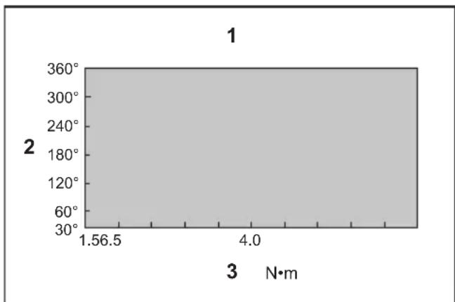
1. Eúpoc Ikavótnac οπερεωng 2. Γωvia περιορφng 3. Pònn
NAPATHPHSH: H ywvia TEPiOtpoqns eivai n ywvia aTTO sncs Tnou TO pTouAoVIXeI OxIXeKata 50% TNC EINUunntc potnc MEXPI TO sncs IOIO TO pTouAoVIOXIXTEI MEPOTN100%.
NAPATHPHSH: H xphon miaac kpuac kaoetac mtaTapiw mtopei va napayei TPOEIDOTOING yia tn XwpntikotnTa mttatapiac tnv evdEign LED kai to BouBntn kai va otapatnoe i aoeos n aeitoupyia tou epyaieiou, akoun ki av eivai TAnpwof opptioevn. Tnv TepiTTwn autn, n ikavotna oTepeowns mtopei va eivai katwepn ano tvnpoiaypaipn oTo TApov Exyeipio.
SYNTHPHSEH
A IPOEOXH: Npiv Tnv EKTaleoN epyaowv EITIOe- WpOngn n ouvtnpoNG, TAVTote va 8eBaiwveOTe OTI n OuaKEUN aTVEpyoToinkE KAI n KaTeTa MntatapiWv exei aqaipeThei.
EiOIOIHsH:MvXpnoImuOnoiTe Tne Iv, Tepaikoc aIepa, diautko, aKoAn n TaPouoe ouic. Mtopeiv a POKnthei aTOxpwatauoc, npapopwwn npwysc.
Tia Tn diatnpnon Tng AΦAIAIa Kai AIONIISTIA Tou TpoiovtoC,oi EIOKEuec KAI OTIOABHNTote aALN epyaia ouvtnpns npuOUIGn TpeTIeVA EKTEAOvTai ano EGOIOBOTneva nepyooTaiaKa Kevtpa EGUINpETnOnc TnS Makita, xnoiOpIoUwTAC TAVTOE AVtAAAKTIA Tng Makita.
IPOAIPETIKA EAPTHMATA
A NPOEXH: Auta ta aaptnata n Tpoopatnata ouviotwvai ia xpnon e to epyaaleio Makita Tou Tepiypaptnke otis oyniec autc. H xpnon OToiowohtote aaawv eapntnatwv n TpoopantmuTswu TPOKAeEIKDuvTOpauaTIOOU e atoua.Nx npnoipootoeite ta eapntnata n Tpoopatnata mOvo ia tynxpnon Tou Tpoopiciovtai
Eav xpeiaeote OTIOaIbHTOTE BOntheia yia TepiooTepec PAnpoopoeis OE oxeon me auta ta Eapntmuata, aTOTAV-0e ITONIKOa Kevtpo Eutnpetnns Makita.
- Pooaaoatak a n
- PpOaTateutiko (quikó, kokivo, mλε, Ktpivo, Tpaoivo)
Kaawo USB
Favrtzos - Naigiabi aospalionc (Kokkivo, pTtivo)
- Γνησια μπαταρία και φορτισής της Makita
NAPATHPHSH: MepiKa oToixia oTn Iota a Tnpei va ouTepiAubovTai oTn ouKeuaia epaaleiou wc stavtp EapntmuTa. Mnpei va diapepuv avaloya e Tn xupa.
TEKNIK ÖZELLİKLER
| Model: DFT024F DFT025F DFT060F | ||||
| Sikma torku Sert tespit yeti 0 | 5 - 2 N·m 1,5 - 6,5 N·m | |||
| Yumusak tespit yeti 0,5 - 2 N·m | 1,5 - 6,5 N·m | |||
| Yüksüz yüz (dev/dak) 260 - 1.600 min | -1 | 100 - 1.300 min1 | ||
| Boyutlar (U x G x Y) BL1815N ba | baryayla 161 mm x 75 mm x 242 mm | |||
| BL1860B baryayla 161 mm x 75 mm x 258 mm | ||||
| Nominal voltaj D.C. 18 V | ||||
| Net ağırlik 1,2 - 1,5 kg | ||||
| Kullanilabilir USB kablosu 661432-2 | ||||
Surekli yapilan arastirma ve gelistirmelerden dolayi, burada belirtilen ozellikler onceden bildilmeksizin degistirilebilir.
Özellikler ükeden ülkeye degişebilir.
- Ağırlik, ekli aksesuara/aksesuarla ve batarya kartusuna®,开荒开荒开荒开荒开荒开荒开荒开荒开荒开荒开荒开荒开荒开荒开荒开荒开荒开荒开荒开荒开荒开荒开荒开荒开荒开荒开荒开荒开荒开荒开荒开荒开荒开荒开荒开荒开荒开荒开荒开荒开荒开荒开荒开荒开荒开荒开荒开荒开荒开荒开荒开荒开荒开荒开荒开荒开荒开荒开荒开荒开荒开荒开荒开荒开荒开荒开荒开荒开荒开荒开荒开荒开荒开荒开荒开荒开荒开荒开荒开荒开荒开荒开荒开荒开荒开荒开荒开荒开荒开荒开荒开荒开荒开荒开荒开荒开荒开荒开荒开荒巴巴巴巴巴巴巴巴巴巴巴巴巴巴巴巴巴巴巴巴巴巴巴巴巴巴巴巴巴巴巴巴巴巴巴巴巴巴巴巴巴巴巴巴巴巴巴巴巴巴巴巴巴巴巴巴巴巴巴巴巴巴巴巴巴巴巴巴巴巴巴巴巴巴巴巴巴巴巴巴巴巴巴巴巴巴巴巴巴巴巴巴巴巴巴巴巴巴巴巴巴巴巴巴巴巴巴巴巴巴巴巴巴巴巴巴巴巴巴巴巴巴巴巴巴巴巴巴巴巴巴巴巴巴巴巴巴巴巴巴巴巴巴巴巴巴巴巴巴巴巴巴巴巴巴巴巴巴巴巴巴巴巴巴巴巴巴巴巴巴巴巴巴巴巴巴巴巴巴巴巴巴巴巴巴巴巴巴巴巴巴巴巴巴巴巴巴巴巴巴宝宝宝宝宝宝宝宝宝宝宝宝宝宝宝宝宝宝宝宝宝宝宝宝宝宝宝宝宝宝宝宝宝宝宝宝宝宝宝宝宝宝宝宝宝宝宝宝宝宝宝宝宝宝宝宝宝宝宝宝宝宝宝宝宝宝宝宝宝宝宝宝宝宝宝宝宝宝宝宝宝宝宝宝宝宝宝宝宝宝宝宝宝宝宝宝宝宝宝宝宝宝宝宝宝宝宝宝宝宝宝宝宝宝宝宝宝宝宝宝宝宝宝宝宝宝宝宝宝宝宝宝宝宝宝宝宝宝宝宝宝宝宝宝宝宝宝宝宝宝宝宝宝宝宝宝宝宝宝宝宝宝宝宝宝宝宝宝宝宝宝宝宝宝宝宝宝宝宝宝宝宝宝宝宝宝宝宝宝宝宝宝宝宝宝宝宝宝宝宝宝马宝马宝马宝马宝马宝马宝马宝马宝马宝马宝马宝马宝马宝马宝马宝马宝马宝马宝马宝马宝马宝马宝马宝马宝马宝马宝马宝马宝马宝马宝马宝马宝马宝马宝马宝马宝马宝马宝马宝马宝马宝马宝马宝马宝马宝马宝马宝马宝马宝马宝马宝马宝马宝马宝马宝马宝马宝马宝马宝马宝马宝马宝马宝马宝马宝马宝马宝马宝马宝马宝马宝马宝马宝马宝马宝马宝马宝马宝马宝马宝马宝马宝马宝马宝马宝马宝马宝马宝马宝马宝马宝马宝马宝马宝马宝马宝马宝马宝马宝马宝鸡宝鸡宝鸡宝鸡宝鸡宝鸡宝鸡宝鸡宝鸡宝鸡宝鸡宝鸡宝鸡宝鸡宝鸡宝鸡宝鸡宝鸡宝鸡宝鸡宝鸡宝鸡宝鸡宝鸡宝鸡宝鸡宝鸡宝鸡宝鸡宝鸡宝鸡宝鸡宝鸡宝鸡宝鸡宝鸡宝鸡宝鸡宝鸡宝鸡宝鸡宝鸡宝鸡宝鸡宝鸡宝鸡宝鸡宝鸡宝鸡宝鸡宝鸡宝鸡宝鸡宝鸡宝鸡宝鸡宝鸡宝鸡宝鸡宝鸡宝鸡宝鸡宝鸡宝鸡宝鸡宝鸡宝鸡宝鸡宝鸡宝鸡宝鸡宝鸡宝鸡宝鸡宝鸡宝鸡宝鸡宝鸡宝鸡宝鸡宝鸡宝鸡宝鸡宝鸡宝鸡宝鸡宝鸡宝鸡宝鸡宝鸡宝鸡宝鸡宝鸡宝鸡宝鸡宝鸡宝鸡宝鸡宝鸡宝鸡