
GLL 315 X Professional - Laser pointer BOSCH - Free user manual and instructions
Find the device manual for free GLL 315 X Professional BOSCH in PDF.
| Product Type | Line Laser Pointer |
| Brand | Bosch |
| Model | GLL 315 X Professional |
| Laser line range | 15 m (reduced range in direct sunlight) |
| Plumb point range | 5 m |
| Leveling accuracy | ±0.2 mm/m |
| Self-leveling range | ±3° | Leveling time | < 4 s |
| Operating temperature | -10 °C to +45 °C |
| Storage temperature | -20 °C to +70 °C |
| Laser class | 2 (power < 1 mW, 630-650 nm) |
| Power supply | 4 x 1.5 V LR6 (AA) batteries |
| Battery life | 24 h (1 line), 14 h (2 lines), 10 h (3 lines) |
| Weight (according to EPTA) | 0.54 kg |
| Dimensions (without platform) | 122 × 83 × 129 mm |
| Dimensions (with platform) | Ø 151 × 203 mm |
| Protection class | IP54 (dust and splash water protection) |
| Leveling | Automatic with tilt compensation up to ±3° |
| Operating modes | Horizontal, vertical (with plumb point), auto-off can be deactivated |
| Included accessories | Laser target, protective case (depending on version) |
| Maintenance | Clean with a soft, damp cloth; do not immerse; store in the case |
| Safety | Do not stare into the beam; do not point at people or animals; only use suitable laser viewing glasses |
| Repairability | Spare parts available through Bosch after-sales service; repair by qualified professional |
Frequently Asked Questions - GLL 315 X Professional BOSCH
User questions about GLL 315 X Professional BOSCH
0 question about this device. Answer the ones you know or ask your own.
Ask a new question about this device
Download the instructions for your Laser pointer in PDF format for free! Find your manual GLL 315 X Professional - BOSCH and take your electronic device back in hand. On this page are published all the documents necessary for the use of your device. GLL 315 X Professional by BOSCH.
USER MANUAL GLL 315 X Professional BOSCH
GLL 3-15 X Professional
Robert Bosch Power Tools GmbH
70538 Sollgart
GERMANY
www.bosch-pt.com
MaKeDoHcN. CtpaHua 58
Srpski Strana 65
71
wJ 78

(5)
IEC60825-1:2014 <1mW,630-650nm
Laser Radiationdo not stare into beamClass 2 laser product
4

English
Safety Instructions

All instructions must be read and observed in order for the measuring tool to function safely. The safeguards integrated into the measuring tool may be compromised if the
measuring tool is not used in accordance with these instructions. Never make warning signs on the measuring tool unrecognisable. SAVE THESE INSTRUCTIONS FOR FUTURE REFERENCE AND INCLUDE THEM WITH THE MEASURING TOOL WHEN TRANSFERRING IT TO A THIRD PARTY.
Warning! If operating or adjustment devices other than those specified here are used or other procedures are carried out, this can lead to dangerous exposure to radiation.
The measuring tool is delivered with a laser warning sign (marked in the illustration of the measuring tool on the graphics page).
If the text of the laser warning label is not in your national language, stick the provided warning label in your national language over it before operating for the first time.

Do not direct the laser beam at persons or animals and do not stare into the direct or reflected laser beam yourself. You could blind somebody, cause accidents or damage your eyes.
If laser radiation hits your eye, you must close your eyes and immediately turn your head away from the beam.
Do not make any modifications to the laser equipment.
Do not use the laser goggles (accessory) as protective goggles. The laser goggles make the laser beam easier to see; they do not protect you against laser radiation.
Do not use the laser goggles (accessory) as sunglasses or while driving. The laser goggles do not provide full UV protection and impair your ability to see colours.
Have the measuring tool serviced only by a qualified specialist using only original replacement parts. This will ensure that the safety of the measuring tool is maintained.
Do not let children use the laser measuring tool unsupervised. They could unintentionally blind themselves or other persons.
Do not use the measuring tool in explosive atmospheres which contain flammable liquids, gases or dust. Sparks may be produced inside the measuring tool, which can ignite dust or fumes.
Keep the measuring tool and the magnetic accessories away from implants and other medical devices, e.g. pacemakers or insulin pumps. The magnets inside the measuring tool and accessories generate a field that can impair the function of implants and medical devices.
- Keep the measuring tool and the magnetic accessories away from magnetic data storage media and magnetically sensitive devices. The effect of the magnets inside the measuring tool and accessories can lead to irreversible data loss.
Product Description and Specifications
Please observe the illustrations at the beginning of this operating manual.
Intended Use
The measuring tool is intended for determining and checking horizontal and vertical lines and plumb points. The measuring tool is suitable for indoor use.
Product Features
The numbering of the product features shown refers to the illustration of the measuring tool on the graphic page.
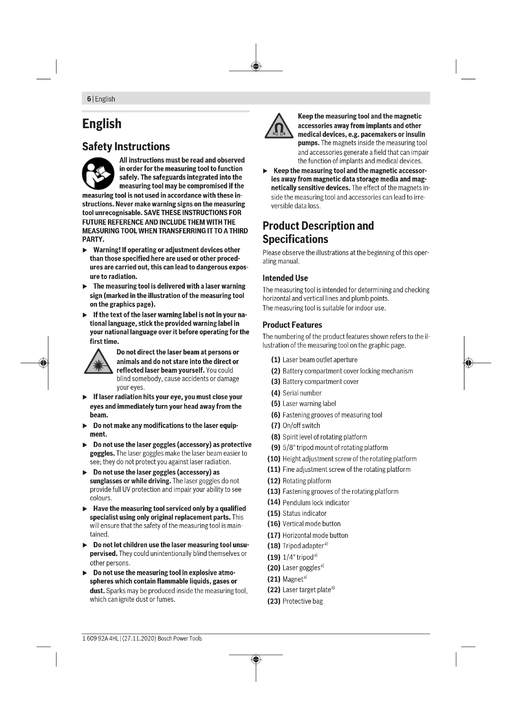
(1) Laser beam outlet aperture
(2) Battery compartment cover locking mechanism
(3) Battery compartment cover
(4) Serial number
(5) Laser warning label
(6) Fastening grooves of measuring tool
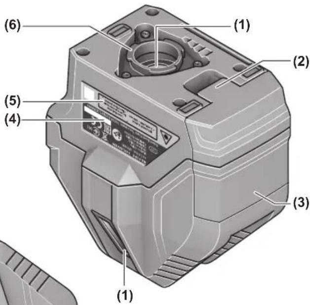
(7) On/off switch
(8) Spirit level of rotating platform
(9) 5 / 8n tripod mount of rotating platform
(10) Height adjustment screw of the rotating platform
(11) Fine adjustment screw of the rotating platform
(12) Rotating platform
(13) Fastening grooves of the rotating platform
(14) Pendulum lock indicator
(15) Status indicator
(16) Vertical mode button
(17) Horizontal mode button
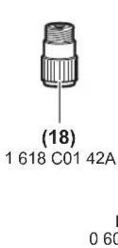
(18) Tripod adaptera)
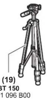
(19) 1 / 4n tripod a
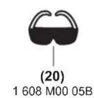
(20) Laser goggles a)
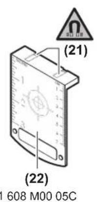
(21) Magneta)
(22) Laser target plate
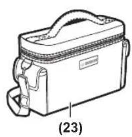
(23) Protective bag
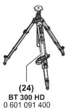
(24) 5 / 8n tripod
a) Accessories shown or described are not included with the product as standard. You can find the complete selection of accessories in our accessories range.
Technical Data
| Line laser GLL 3-15 X | |
| Article number | 3601 K63 E.. |
| Working rangea) | |
| -Laser lines 15 m | |
| -Plumb point 5 m | |
| Laser line levelling accuracyb)(c) | ±0.2 mm/m |
| Typical self-levelling range ±3° | |
| Typical levelling time < 4 s | |
| Operating temperature -10 °C to +45 °C | |
| Storage temperature -20 °C to +70 °C | |
| Max. altitude 2000 m | |
| Relative air humidity max. 90 % | |
| Pollution degree according toIEC 61010-1 | 2E) |
| Laser class 2 | |
| Laser type < 1 mW, 630-650 nm | |
| C6 | 1 |
| Divergence | |
| -Laser line 1.5 mrad | |
| -Plumb point 1.5 mrad | |
| Tripod mountF) | 5/8" |
| Batteries 4 × 1.5 V LR6 (AA) | |
| Operating time approx.G) | |
| -With 1 laser line 24 h | |
| -With 2 laser lines 14 h | |
| -With 3 laser lines 10 h | |
| Weight according toEPTA-Procedure 01:2014 | 0.54 kg |
| Dimensions (length × width × height) | |
| -Without rotating platform 122 × 83 × 129 mm | |
| -With rotating platform | Dia. 151 × 203 mm |
Line laser GLL 3-15 X
Protection rating (excluding bat- IP 54 (dust and splash- tery compartment) proof)
A) The working range may be reduced by unfavourable environ-mental conditions (e.g. direct sunlight).
B) ex-works
C)At 20-25°C
D) The values stated presuppose normal to favourable environmental conditions (e.g. no vibration, no fog, no smoke, no direct sunlight). Extreme fluctuations in temperature can cause deviations in accuracy.
E) Only non-conductive deposits occur, whereby occasional temporary conductivity caused by condensation is expected.
F) Only available in combination with the rotating platform The serial number (4) on the type plate is used to clearly identify your measuring tool.
Assembly
Inserting/changing the batteries
It is recommended that you use alkaline manganese batteries to operate the measuring tool.
To open the battery compartment cover (3), press on the locking mechanism (2) and remove the battery compartment cover. Insert the batteries.
When inserting the batteries, ensure that the polarity is correct according to the illustration on the inside of the battery compartment.
If the status display (15) flashes, the batteries have to be replaced.
Always replace all the batteries at the same time. Only use batteries from the same manufacturer and which have the same capacity.
Take the batteries out of the measuring tool when you are not using it for a prolonged period of time. The batteries can corrode and self-discharge during prolonged storage in the measuring tool.
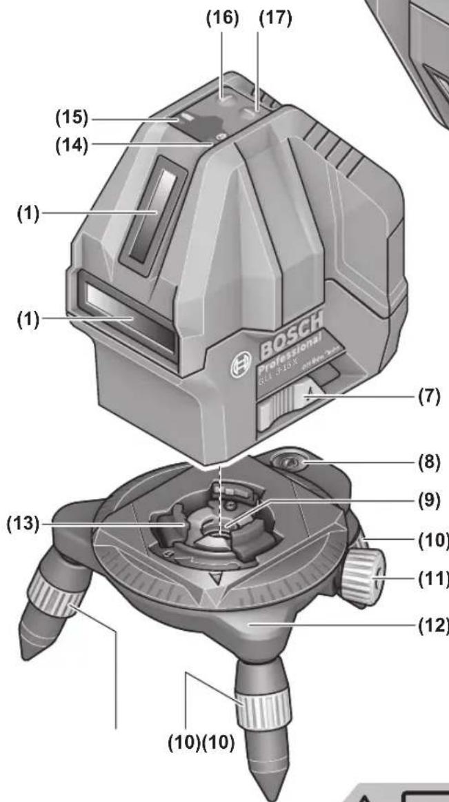
Working with the Rotating Platform (see figure A)
You can use the rotating platform (12) to rotate the measuring tool 360irc around a central, always visible plumb point. This enables you to set up the laser lines precisely, without having to change the position of the measuring tool.
Place the measuring tool on the rotating platform (12) so that the fastening grooves (13) of the rotating platform fit between the corresponding fastening grooves (6) on the bottom of the measuring tool. Turn the measuring tool clockwise to lock it on the rotating platform.
Unscrew the legs of the rotating platform (12) with the height adjustment screws (10).
Roughly align the rotating platform using the spirit level (8). If the measuring tool is mounted on the rotating platform (12), you can use the fine adjustment screw (11) to align vertical laser lines precisely with reference points.
Operation
Starting Operation
Protect the measuring tool from moisture and direct sunlight.
Do not expose the measuring tool to any extreme temperatures or fluctuations in temperature. For example, do not leave it in a car for extended periods of time. If it has been subjected to significant fluctuations in temperature, first allow the measuring tool to adjust to the ambient temperature and then always carry out an accuracy check before continuing work (see "Accuracy Check of the Measuring Tool", page 9). The precision of the measuring tool may be compromised if exposed to extreme temperatures or fluctuations in temperature.
Avoid substantial knocks to the measuring tool and avoid dropping it. Always carry out an accuracy check before continuing work if the measuring tool has been subjected to severe external influences (see "Accuracy Check of the Measuring Tool", page 9).
- Switch the measuring tool off when transporting it. The pendulum unit is locked when the tool is switched off, as it can otherwise be damaged by big movements.
Switching On/Off
To switch on the measuring tool, slide the on/off switch (7) to the "on" position (for working with the pendulum lock) or to the "on" position (for working with automatic leveling). The status display (15) lights up. Immediately after switching on, the measuring tool sends a horizontal laser line out of the front outlet aperture (1).
Do not direct the laser beam at persons or animals and do not stare into the laser beam yourself (even from a distance).
To switch off the measuring tool, slide the on/off switch (7) to the "Off" position. The status indicator (15) goes out. The pendulum unit is locked when the tool is switched off.
- Never leave the measuring tool unattended when switched on, and ensure the measuring tool is switched off after use. Others may be blinded by the laser beam.
If the maximum permitted operating temperature of 45ircC is exceeded, the tool shuts down to protect the laser diode. Once it has cooled down, the measuring tool is operational again and can be switched back on.
Deactivating the automatic shut-off function
The measuring tool automatically switches itself off after 30 min of operation.
To deactivate the automatic shut-off, hold down either the vertical mode button (16) or the horizontal mode button (17) for 3 seconds when switching on the measuring tool. The laser beams will flash briefly after 3 seconds if the automatic shut-off function is deactivated.
To activate the automatic shut-off function, switch the measuring tool off and on again (without holding down a button).
Operating Modes
The measuring tool has several operating modes, which you can switch between at any time. The horizontal and vertical modes can be switched on and off independently of each other. After switching on, the measuring tool is in horizontal mode.
All operating modes can be selected with both automatic levelling or the pendulum lock.
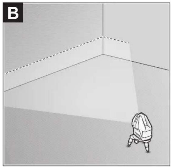
Horizontal mode (see figure B)
In horizontal mode, the measuring tool sends out a horizontal laser line pointing forwards.
To switch the horizontal laser line off or on, press the horizontal mode button (17).
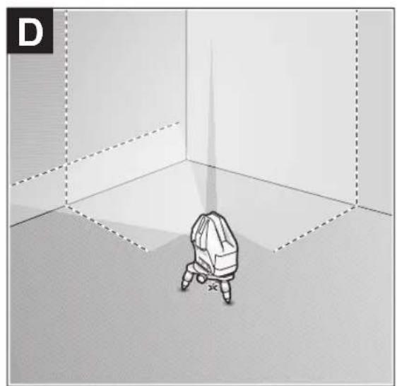
Vertical mode and plumb point (see figures C-D)
The measuring tool has two vertical operation modes:
Vertical laser line forwards
Vertical laser line forwards and to the right-hand side A plumb point is additionally projected downwards in vertical mode.
To switch the vertical mode on/off or to change the vertical mode, press the vertical mode button (16) repeatedly until the required operating mode is reached.
Automatic Levelling
Working with automatic levelling
Position the measuring tool on a level, firm surface or attach it to the rotating platform (12).
For work with automatic levelling, slide the on/off switch (7) to the "on" position.
The automatic levelling function automatically compensates irregularities within the self-levelling range of ± 3irc . The leveling is finished as soon as the laser lines stop moving.
If automatic levelling is not possible, e.g. because the surface on which the measuring tool stands deviates by more than 3irc from the horizontal plane, the laser beams will flash quickly.
If this is the case, set up the measuring tool in a level position and wait for the self-levelling to take place. As soon as the measuring tool is within the self-levelling range of ± 3irc , the laser beams will light up continuously.
In case of ground vibrations or position changes during operation, the measuring tool is automatically levelled again.
Upon levelling, check the position of the laser beams with regard to the reference points to avoid errors arising from a change in the measuring tool's position.
Working with the pendulum lock
For work with the pendulum lock, slide the on/off switch (7) to the "On" position. The pendulum lock indicator (14) lights up red and the laser lines continuously flash slowly.
For work with the pendulum lock, automatic levelling is switched off. You can hold the measuring tool freely in your hand or place it on a sloping surface. This means that the laser beams are no longer levelled and no longer necessarily run perpendicular to one another.
Accuracy Check of the Measuring Tool
Influences on Accuracy
The largest influence is exerted by the ambient temperature. In particular, temperature differences that occur from the ground upwards can refract the laser beam.
Since the temperature stratification is greatest at ground level, you should mount the measuring tool on a tripod and position it in the centre of the work surface, wherever this is possible.
In addition to external influences, device-specific influences (e.g. falls or heavy impacts) can also lead to deviations. For this reason, check the levelling accuracy each time before beginning work.
First check the height accuracy and levelling accuracy of the horizontal laser line, then the levelling accuracy of the vertical laser line.
Should the measuring tool exceed the maximum deviation during one of the tests, please have it repaired by a Bosch after-sales service.
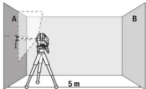
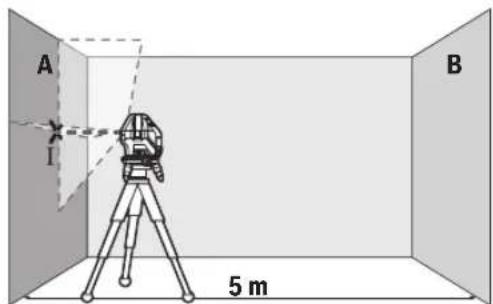
Checking the Height Accuracy of the Horizontal Line
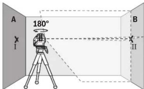
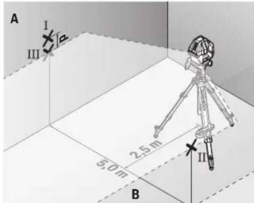
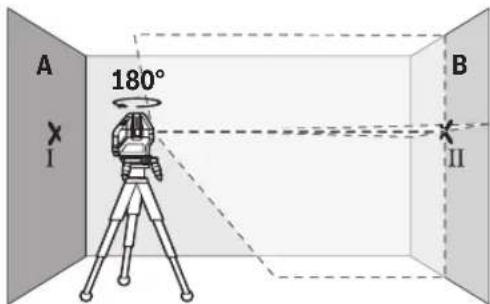
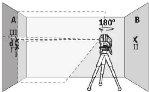
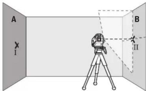
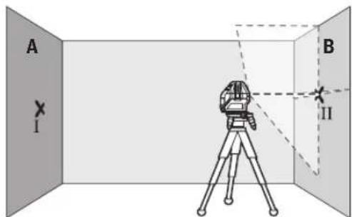
For this check, you will need a free measuring distance of 5 m on firm ground between two walls (designated A and B).
- Mount the measuring tool close to wall A on the rotating platform (12) or a tripod (24), or place it on a firm, flat surface. Switch on the measuring tool in the mode with automatic levelling. Switch on horizontal mode and vertical mode with a laser line forwards.
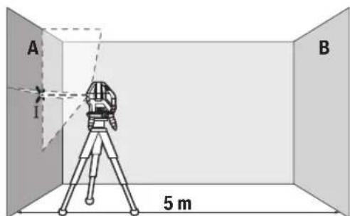
- Aim the laser at the closer wall A and allow the measuring tool to level in. Mark the middle of the point at which the laser lines cross on the wall (point I).
-
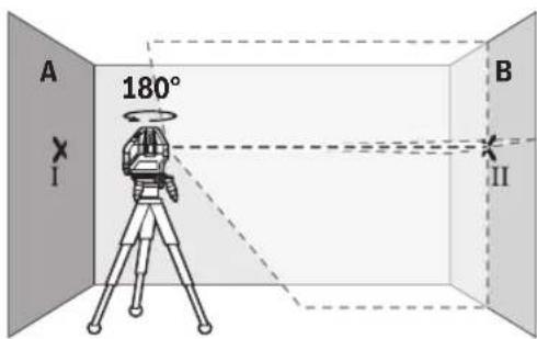
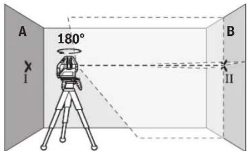
Turn the measuring tool 180irc , allow it to level in and mark the point where the laser lines cross on the opposite wall B (point II).
-
Position the measuring tool - without rotating it - close to wall B, switch it on and allow it to level in.
Align the height of the measuring tool (using the tripod or by placing objects underneath as required) so that the point where the laser lines cross exactly hits the previously marked point II on wall B.
- Turn the measuring tool 180irc without adjusting the height. Aim it at wall A such that the vertical laser line runs through the already marked point I. Allow the measuring tool to level in and mark the point where the laser lines cross on wall A (point III).
- The discrepancy d between the two marked points I and III on wall A reveals the actual height deviation of the measuring tool.
The maximum permitted deviation on the measuring distance of 2 × 5m = 10m is as follows:
10 m × ±0.2 mm/m = ±2 mm. The discrepancy d between points I and III must therefore amount to no more than 2 mm.
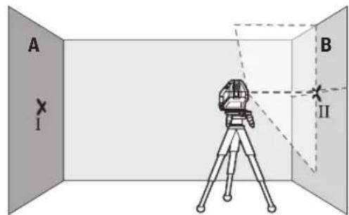
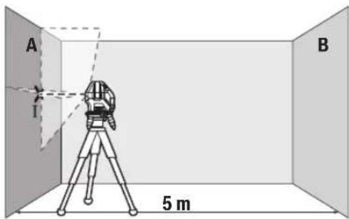
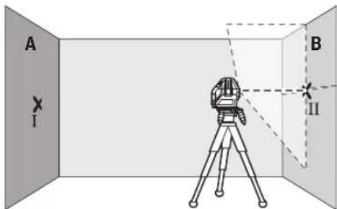
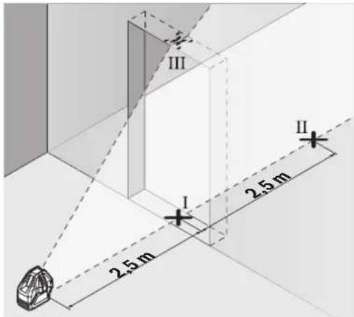
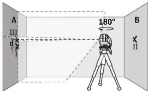
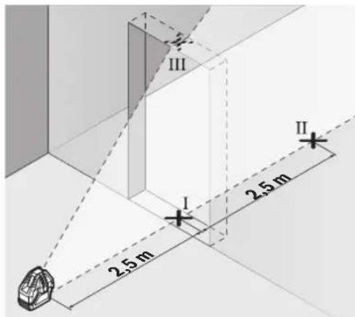
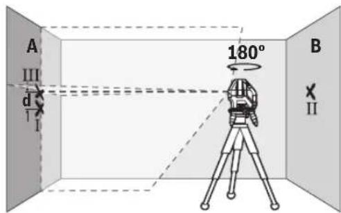
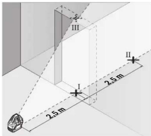
Checking the Level Accuracy of the Horizontal Line
For this check, you will need a free area of 5 × 5m .
- Mount the measuring tool in the middle between walls A and B on the rotating platform (12) or a tripod (24), or place it on a firm, flat surface. Switch on the measuring tool in the mode with automatic levelling. Switch on horizontal mode and allow the measuring tool to level in.
10|English
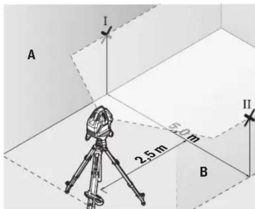
- At a distance of 2.5m from the measuring tool, mark the centre of the laser line on both walls (point I on wall A and point II on wall B).
- Set up the measuring tool at a 5 m distance and rotated by 180irc and allow it to level in.
Align the height of the measuring tool (using the tripod or by placing objects underneath as required) so that the centre of the laser line exactly hits the previously marked point II on wall B. - Mark the centre of the laser line on wall A as point III (vertically above or below point I).
- The discrepancy d between the two marked points I and III on wall A reveals the actual horizontal deviation of the measuring tool.
The maximum permitted deviation on the measuring distance of 2 × 5m = 10m is as follows:
10 m × ±0.2 mm/m = ±2 mm. The discrepancy d between points I and III must therefore amount to no more than 2 mm.
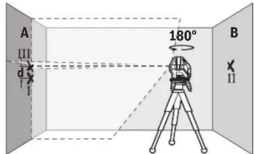
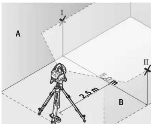
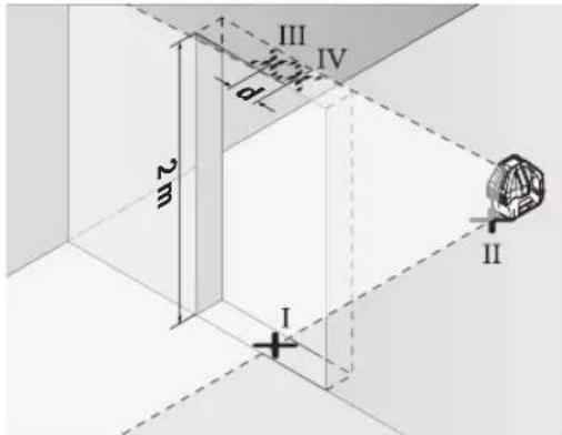
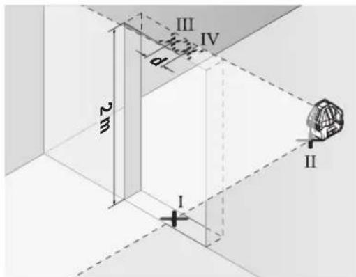
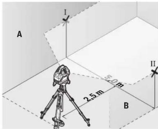
Checking the Level Accuracy of the Vertical Line
For this check, you will need a door opening (on solid ground) which has at least 2.5m of space either side of the door.
- Place the measuring tool 2.5m away from the door opening on a firm, flat surface (not on the rotating platform (12) or a tripod). Switch on the measuring tool in the mode with automatic levelling. Switch on vertical
mode with a vertical laser line forwards and aim the vertical laser line at the door opening. Allow the measuring tool to level in.

- Mark the centre of the vertical laser line on the floor of the door opening (point I), 5 m away on the other side of the door opening (point II) and on the upper edge of the door opening (point III).

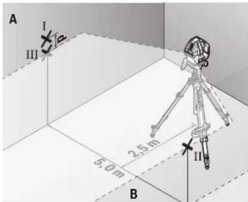
- Rotate the measuring tool 180irc and position it on the other side of the door opening, directly behind point II. Allow the measuring tool to level in and align the vertical laser line in such a way that its centre passes through points I and II exactly.
- Mark the centre of the laser line on the upper edge of the door opening as point IV.
- The discrepancy d between the two marked points III and IV reveals the actual vertical deviation of the measuring tool.
Measure the height of the door opening.
You can calculate the maximum permitted deviation as follows:
Doubled height of the door opening × 0.2mm / m
Example: At a door opening height of 2 m, the maximum deviation amounts to
2× 2m× ± 0.2mm / m = ± 0.8mm .The points III and IV
must therefore be no further than 0.8mm from each other.
Working Advice
Only the centre of the laser point or laser line must be used for marking. The size of the laser point/the width of the laser line changes depending on the distance.
Working with the Laser Target Plate
The laser target plate (22) improves visibility of the laser beam in unfavourable conditions and at greater distances. The reflective surface of the laser target plate (22) improves visibility of the laser line. The transparent surface enables the laser line to be seen from behind the laser target plate.
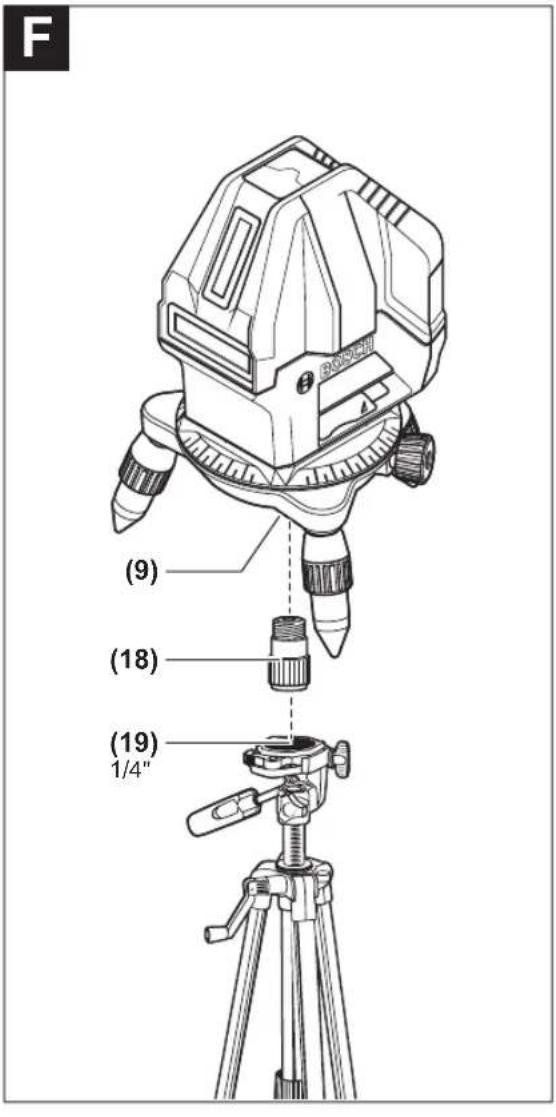
Working with the Tripod (Accessory) (see figure F)
A tripod offers a stable, height-adjustable support surface for measuring. Place the measuring tool on the rotating platform (12) to assemble the measuring tool on a tripod. Assembly on a 5 / 8" tripod: Place the rotating platform with the 5 / 8" tripod mount (9) on the thread of a commercially available 5 / 8" tripod (24) or a commercially available building tripod. Tighten the rotating platform using the locking screw of the tripod.
Assembly on a 1 / 4'' tripod (see figure F): Screw the tripod adapter (18) (accessory) into the 5 / 8'' tripod mount (9) of the rotating platform. Place the tripod adapter with the 1 / 4'' tripod mount on the thread of a 1 / 4'' tripod (19) or a commercially available camera tripod. Tighten the tripod adapter using the locking screw of the tripod.
Roughly align the tripod before switching on the measuring tool.
Laser Goggles (Accessory)
The laser goggles filter out ambient light. This makes the light of the laser appear brighter to the eye.
Do not use the laser goggles (accessory) as protective goggles. The laser goggles make the laser beam easier to see; they do not protect you against laser radiation.
Do not use the laser goggles (accessory) as sunglasses or while driving. The laser goggles do not provide full UV protection and impair your ability to see colours.
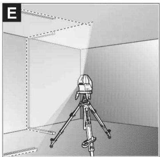
Example applications (see figures B-E)
Examples of possible applications for the measuring tool can be found on the graphics pages.
Maintenance and Service
Maintenance and Cleaning
Keep the measuring tool clean at all times.
Never immerse the measuring tool in water or other liquids. Wipe off any dirt using a damp, soft cloth. Do not use any detergents or solvents.
The areas around the outlet aperture of the laser in particular should be cleaned on a regular basis. Make sure to check for lint when doing this.
Only store and transport the measuring tool in the protective pouch (23).
If the measuring tool needs to be repaired, send it off in the protective pouch (23).
After-Sales Service and Application Service
Our after-sales service responds to your questions concerning maintenance and repair of your product as well as spare parts. You can find explosion drawings and information on spare parts at: www.bosch-pt.com
The Bosch product use advice team will be happy to help you with any questions about our products and their accessories.
In all correspondence and spare parts orders, please always include the 10-digit article number given on the nameplate of the product.
Great Britain
Robert Bosch Ltd. (B.S.C.)
P.O.Box 98
Broadwater Park
North Orbital Road
Denham Uxbridge
UB95HJ
At www.bosch-pt.co.uk you can order spare parts or arrange the collection of a product in need of servicing or repair.
Tel. Service: (0344) 7360109
E-Mail: boschservicecentre@bosch.com
You can find further service addresses at:
www.bosch-pt.com/serviceaddresses
Disposal
Measuring tools, accessories and packaging should be recycled in an environmentally friendly manner.

Do not dispose of measuring tools or batteries with household waste.
Only for EU countries:
According to the Directive 2012/19/EU, measuring tools that are no longer usable, and according to the Directive 2006/66/EC, defective or used battery packs/batteries, must be collected separately and disposed of in an environmentally correct manner.
Français
Robert Bosch (France) S.A.S.
www.bosch-pt.com/serviceaddresses
www.bosch-pt.com/serviceaddresses
Eliminación
www.bosch-pt.com/serviceaddresses
Eliminação
www.bosch-pt.com/serviceaddresses
Tasfiye
IaTn3rOToBnEHHyKa3aHa Ha NocneHHe CTpaHnCe 06- IIOxKn PykoBoDCTBa HnHa KOpnyce Hdenn.
KoHTaKTHa HOpMaun OTHocHtBHO MMnOtpa CopepKHTcHa yNaKOBKe.
Cpok cnyx6bH3dennn
Cpok cnjkbbln3denncoctabnet7net.He pekomehnyer cK3Knpyataunnohtcehenn5netxpaehnnc DaTbI n3rTOBHeHn6e3 npedBaPntelho npOBepkn (daty n3rTOBHeHn CM. Ha 3TNKeTke).
Ipeueenb KpntHuecknx OTka3OB H OwH6OuHbIe DeiCTBn IepcoHaHa HIN NOnb3oBaTeN
-HeHCnOJIb3OBaTbPnIIOBBAHENINDbIMAHENOCpeCTBeHHO H3 Kopnyca H3dEINIA
38 | Pycckn
-HeHCIOB3OBaTb HAOTKpbITOMIPOCTpaHCTBE BO BpEMn DOxN(BpaCnblnEmoB OBe)
-He BKNIOUaTb npn nonaHNN BOBbl B Kopnyc
Kpntepnn npedeBhbix coctoHHn
- noBpeKdEn KOpnyc n3dennr
Tnn n nepnoohnoctb texnueckoro o6cnyhbHnpeKomeHnyetc ouHCTNtB HnctpyMeHT OT nbInn noCne KaXdOro hncnbl3OBaHN.
Xpahene
-Heo6xOJIMO xpaHb B cyXOM MeCTe
HeoXOJMO XpaHHTBdAINOT HCTOHNKOB NOBbIeH HBIX TEMNEPAtyp IN BO3dEICTBnCOnHehBix Nyue
- npxpaHEnn Heo6xOIMO n36eratb pe3KOro nepenada TemnepaTyp
-eCNHHTpyMeHNTNOCTaBnAETCBA MFRKOyCMKEHINIIACTKOBOMKeCEpeKOMeHDyETCAxpaHHTb HHTpyMeHTB30J3aUNTHOYNaKOBKe
- noPpObHbIe Tpe6oBaHN K yCNoBnM XpaHeHH CMOtpnte B FOCT 15150-69 (YcNoBne 1)
TpaHcnpToPbovBa
KaTeROpHueCKeH He DonyckaetcnaJeHne HIOb6Be MExaHnueCKe BO3dEiCTBnHa yNaKOBky npH TpaHcNopTHPOBKe
- npn pa3py3ke/norpy3ke He donyckaetc HcnoIb30BaHne IIO6oTo Bua texnKn, pa6oTaOe ne npHHunny 3aKmMa ynaKOBKn
noDpObHbIe Tpe6oBaHHaK yCNoBnAM TpaHCnOpTnPoBKn CMOTPHTB FOCT 15150-69 (YcNoBne 5)
Yka3aHnnoTexHnke6e30nacchoCTn

IJa o6ecneueHH 6e30aHCHn HAdexKHO pa6oTbC n3MepHTenbHm HnCTpyMeHToM DoJXhbl 6b1b IpOuHTaHb H co6nIOaTbcB CBe nHCTpyKcHn. NcNoJIb3ObaHHe n3MepH
TeNbHOro HnCTpyMeHTa He B COOTBcTbHn C HactOnuMH yKa3aHHMa YpeBaTo NOBpeXdeHem HnterPnpOBaHNbIX 3aunThbIX MexAHN3MOB. HNKOrJa He H3MeHnTe Do Hey3HaBaemocTH NpeynpEnTeNbHbIe TabnKn Ha n3-MepNTeNbHom HnCTpyMeHTe. XOPOIo COXPAHNTE 3TN IHCTPyKUHN INPEPDABAITE NX BMECTC INPEPeDAYEN H3MEPTEJBHO Tn HnCTpyMeHTA.
OCTOPOXHO -npHMeHeHHe HcTpyMeHTOBdIg 6cnyKHNBAHn HNIOCTnPOBKN HN IpOeDyP Texo6cnYKBAHn, KpOME yKa3aHHbIX 3deCb, MoKeT npHBecTN KONACHOMY BO3dEhCTBNO 3NPyHeHn.
N3MepHTenbHbI HhCTpyMeHNTocTabnEeTc C npedynpedntenbHO Tabnuko Na3epHoro N3nyehna (noKa3aHa Ha CTpaHnue c H3o6paXeHHem N3MepHTenbHoTo HHCTpyMeHTe).
EcnTKeCT PnepDynpEnTeBHO Ta6nHKn Na3epHOro 3nyueHHe Ha BaWem poNOM RaBiKe, npep nepBbIM 3anyckOM B KcnnyatauHIO 3akneIe ee hakneiKoHa BaWem poNOM RaBiKe, KOtOpA HxOaNT B 06bem NoCTABKN.
He HanpaBnIte Nyu na3epa Ha IIOeHnn XHBOTbIX n Camn He CMOTpTe Ha npmoH nn OTPxaembl nyu na3epa. 3TOT nyu moKet CInENTb IIOe, CTaTb pNPHHO HeCuaCTHO CNYa HIN NOBpeNTb Fna3a.
B cnyae nonadaHnnaepHoro lyuBa rna3 rna3a hyxho HamepeHNO 3akpbItb HemeDneHNO OTBepHytbcraO Tnya.
He MeHnIe HnHcero B nAa3epHom yctpoiCTBe.
He hcnb3yte oukn npa6oTb c naephblm HnCTpyMeHToM (pnhadneXHoctb) B KaueCTBe 3aunTbIX OOKOB. OKn dnn pa6oTb C naepHbIM HnCTpyMeHToM oecneuBaIOT lyuwee pacno3HaBaHne naepHoro Lyua, Ho He 3aunuAoiT OT naepHoro N3nyeHna.
He hcnno3yHTe ouKn dnn pa6oTbI c na3epHbIM HnCTpyMeHTOM (npHHaNDexNHOctb) B KaueCTBe coNHue3aHTbIX OOKOB HIN 3a pyEm. OOKn dnn pa6oTbIC naepeom He oecneuHaBOT 3aunTy OT YΦ-H3nyeHn MeuahOT npabHbHOMy CBETOBCPnAHTIO.
Pemont H3MepHTeHbHO HNCTpyMeHaTa pa3peuaeTcBbIOHNrTa TOnbKO KBaHnHpOBAHHOMy NepcoHanyTOIbKO CHCIOB3OBAHmOpHnHaHbHbIX 3aHcTei.3TNMOEcecneHbAETc6e3oNaCHOCTb H3MepHTeHBO HNCTpyMeHaTa.
He No3B0JrTe DeTAM NOnb3OBAbCra Na3ePbHIM H3-MepHTeJIbHbIM HnCTpyMeHrOM 6e3 PnHcMoTpA.ETMOTy TNO HeoctopoxKHOCTN OCLeNTb Ce6a HIN NOCTOPOHHX IIOJe.
He pa6oTaTe Cn3MepHTeNbHbIM HnCTpyMeHToM Bo B3pbIBOOnaCHOpe, No6Hn3OcTH OT RopOHx HnKocTei, Ra3OB NblIN. Bn3MepHTeNbHOM HnCTpyMeHTo MOryT 06pa3ObaTbcraNcPbI,OT KOTOpBix MoKeT BOCnnaMeHHTbCra NblN nI npbl.
He yctahabHbAte H3MepeHtBbHbI
HhCTpyMeHT MArHHThbIe PnHaadJeXHoCTN
B6n3H NmPiHaTbTO BnPoUHX MeHn-
CnHCKx AnnapaTOB, HAp.., KApDHOCTMMyTA
TopoB HNCyHNOBbIX HAcOCOB. MaHTbI H3-
MePHTeBHO HcTpyMeHTa N pHaHaJIeXHOCTN CO3dIoT None, KOToPOe MOKeT OTPuCaTeBHO BnHrTa Ha paBoTy HmPiHaTbTOB Me-
DiuHcknx annapatoB.
ДерхитЕнзМерпгельнIHСТРМЕNTИ Магншtleп ринадлесхочTN BDAHOT MaHRTHbIX HOCHTeNEДaHHbIX N OT pIN6OpoB, YyBCTBHTeNBbIX KMARHTHOMy nIOI.Bo3dEChTBHeMaHRTOB Имрпгельно HHCTPymeHTa I npHaJaLNeXHOCTeM OMOKET pINBeCTN K Heo6paTmmoNotpe DaHHbIX.
OnncanHe npoDyKta n ycnyr
IpoKanyIcTa,co6JIIOJaIte HIIIOCTpaIIN B HAaIe pyKOBOdCTBaNo 3KcNpyatauIN.
PpHMeHeHnNoHa3NaeHHo
H3mePHTeBbHINHCTpyMeNTnpedHa3NaueHnIOnpeDeneHHN PPOBepKN Ropn3OHTaBbIX N BepTKaJIbHbIX INHHN NTBCOB.
H3mePHTeBHy HnHcTpymeHT npedHa3haueH dIy HCNoJIb30BaHHa BHYTPN NOMeHNI.
H306paXeHHbIe COCTaBHeIy aACTn
Hymepaun npedctabnEHbIX COCTABbIX qacte BbINOnHeHa no H3o6paKeHHIO H3MePHTeBHO IHCTpyMeHTa HA cTpaHnCe C nllnoctpauqnnm.
(1)OTBepCTneIyBbIXOaIa3epHoroLyuA
(2)ΦHKcATOP KpbIbIKN batapeHOrO OTeKa
(3) Kpbilka 6batapeHoro oTceka
(4) CepiHbH HOpem
(5)PpeynpeHnTeBna Ta6nueKa na3epHoro n3nyeHHN
(6)Kpenexhbltea3bHm3peHtBHOHHTpyMeHa
(7)BbIKnOaTeNb
(8) Batepnap noBopToHn nIaTOpMbI
(9)THe3do noiTuATnB 5/8"noBOpOTHOIaTFOpmbl
(10) BnHTbpepynpOBKn NO BbICote NOBOPOTHOI pT-
(11) BnHT TOH peryI npOBKn NOBOPoTHOINnATOpMbI
(12) Nobopotha nlafoPMa
(13) Kpenexhble na3bl NobopoTHoIaTOpMbI
(14) INHdkaTOpΦKcMmMaTHnKa
(15)Инданкатор с Coastern
(16) KhoIka BepTKaJIbHOro peXnMa pa6Otbl
(17) KhoIka ropu3oHTaIbHOro peKIMpa6oTbI
(18) Aaantep noi taTnB
(19)UtAtnB 1/4
(20) Oukn da pa60bI c na3epHbIM HHTpyMeHToMa
(21) MarHHn?
(22) Bn3nnpa Mapka dna IaepHoro lyuca
(23) 3aunTHbIy cheXon
(24) 5/8
a)N3o6paXeHHbIeMHONCAHbIe npHaadneXhOCTHe BXOJATBCTAHdpTbHIO6bEMnocTbKII.IONHbI accOPTMENT npHaadneXhOCTe BbHaJeTeBaHwe npPorpMaMe npHAdneXhOCTe.
Texnueckne daHbIe
BkJIIOUeHHe MHCTpymEHa
3aunuatae H3MeepntbHbHnHctpymENT O Bnarn npMbx COHeyBx Nyue.
He noDBepraTe H3MepnteBbHbI HnCTpyMeT B03-DeNCTBIO 3KCTpeMaIbHBx TEMnepaTp H TEmnpaTpybIX NepenaO. HanpImep, He ocTabIyTe ero Ha IINITeBHOE BpEM RA BAtOMoHne. Ppi 3NaHTeBbIX KOleBaHHx TEMpePaTybl Chauana daIte TEMpePaType H3MepNTbHOrO INHCTpyMeTA Cta6Hn3n3nipoBaTbcN, H
npexJe yem npoJoxKaTb paOtaB c HNCTpyMeHOM, BcERda npOBepaIte ero ToHocTb (cm. KOHTpOJIb ToHOC Tn N3MepNTeNbHO IHCTpyMeHa", CtpaHua 41). 3KCTpeMaJIbHbIe TempepaTyIb I TeMpepaTyIbIe nepeIaIbMoYr OTPuCaTeNbHO BInrTa HToHoCTb N3MepNTeNbHO IHCTpyMeHa.
H36eraTe CNbHbIX ToUcKOB NnadeHHN H3MepHTeBHO HOHCTpyMeNTA. Nocne CNbHbIX BHeuHXN BO3deiCTBn HA H3MEpHTeBHy INHCTpyMeHT peKOMeHdyETcnpoBePHTb ERO TOHOCb, npEeJe Yem IpOToJXaTb pa6oTaTb C H3CTpyMeHTOM (CM., KOHTPOBtTOHOCTH H3MepHTeBHO IH3CTpyMeNTA", CtpaHnca 41).
Pn TpaHcnpTbPOBKe BbIKIOaHTe N3MePteNBbHINHCTpymENT.Pn BBKIOUeHN 6IOKIPyETcMaTHN-KOBbM MEXaHH3M, KOTOpB INaHe Pn CNbHBx DnHexHHX MoKET 6bITb NOBpeJDeH.
BkHoueHne/BbIKHoueHne
YtO6bI BKNIOUHTb N3MePHTeHBHbINHCTpymENT, nepeBnHbTe BbIKIOuATElb (7) B NOJIOKeHne «On» (nna paobTbCΦHKCATOPOMMaTHNkA)nHnB NOJIOKeHne «
On»(ДЯ pa6Otblc ABTOMaTHueCKHIM HINBENHOBaHNEM) INHdkaTOp COCTOHHNIA(15)3aropaETc. Cpa3y nocne BKNIOUeHHN I3MePHTeJIbHbI INHCTpyMeNT npoeuPYet rOpH3OTaJIbHyIO Na3epHyIO NINHIO H3 nepeHrero OTBepCTHn DnA BbIXOda Na3epHOro Lyua(1)
He HanpaBnIte Na3epHbI Nyu Ha IIOe Hm XHBOTHbIX HcMOTpHTe camn B Na3epHbI Nyu, B TOM YNCne H c6oJbIoro pacCTOHHa.
YTo6bI BbIKIOHTb N3MePntBbHbN HnCTpyMeT, nepeBdINbTe BbIKIOaTeNb (7) B NOIOXeHne «Off». INdNKATOp COCTOHHA (15) rachET. Pn BbIKIOUeHHM MaTHHKOBBI mexAHm3M 6nOKpyetcra.
He octabnIte H3MpTeNbHbI HNCTpyMeT 6e3 npHcMoTp a N bIKIOaHT e3MpTeNbHbI HNCTpyMeT nOcne HCIOB3OBAHJ. DpyrHe Iua MoYr 6bTb ocIeJIeHbI na3epHbIM NyCm.
PnnpBbIeHNPipeIbHO DoNcyTmOH pa6oey TempeIpyb I 45 irc C npOncxOHT BbKIIIOueHneIy3aUHTbIa-3epHOrO dnoHa. Pocne oxLnXJeHn H3MePntEhbln HnCTpymEt ONrTb rOToB KpaOte HMOKeT bItb CHOBa BKIOUeH.
DeakTHBaunrABOMaTHueCKOroBbIKIOUeHHN
Iocne 30 MHH. pa6oTbH n3MePHTeBHy HnHCTpyMeHT aBTO-MaTHueCKH BbIKIOuAeTCR.
YTo6bI DeakTNBnPOBaTb ABTomuueckoe OTKIOUeHne, npB BKIOUeHHN N3MepHTeNbHO INHCTpyMeHTa YdEpxHBaTe KHOKNy BepTKaJIbHOro pexHMa pa60tBu (16) HIN KHONKY rOpN3OHTaJIbHOr peXHMa pa60tBu (17) HaxaToB TteHne 3c. Pocne DeakTNBaun ABtomuueckoro OTKIOUeHHN na-3epHbI lyuN KOPOTKO MmraH Tepe3 3c.
YTO6bI aKTHBnPOBaT bAToMaTHueCKoe BbIKIOUeHHe, BblKIOUHTe N3MePHTeNbHbI INHCTpyMeHNT CHOBA BKIOUHTeero(He HaXHMa HA KHOKNy).
Pexmmbl pa60tbl
N3mepntenbHbHnHCTpyMeHTnMeet HeckoIbKOpeKHMOB pa60tbl, KOTOpble MOXHO nepeKIOUaTb B IIO6O MoMeHT. TOpH3OHTaBbHbN BePTHKaIbHbHpeKIMbI pa60tbl MOXHO BKIOUaTb N BkIOUaTb He3aBnCMO dpyr OT dpyra. Iocne BkIOUeHnI3MepNTenbHbHnHCTpyMeHT HaxODITcB TropHOHTaJIbHOM peKIMpe60tbl.
BcepeKmbpa60tbMOxHO BKNIOaTb cABTOMaTHueckm HNBENPOBaHHeM C 6IOKNPOBKO MaTHNa.
Topn3oHTaIbHbI pexHM pa6Otbl (cm.pnc.B)
B ropuHTaIbHOM pexKIMe I3MePntIbHbI IHCTpyMeNT npoeuPyET OHy ropuHTaIbHyIO na3epHyIO INHHIO BnepeD.
YTO6bl BKNIOHTb HIN BBIKIOHTb TOPN3OHTaIbHyIa3epHyIO IHHIO, HAKMTe KHOITky TOpN3OHTaIbHOro peKIMpa60tbl (17).
BepTKaJIbHbI pEXHM pa6OtBI H TOUKN OTBeCa (CM.pHC.C-D)
HamepeTEnbHbI HnCTpyMeHT NmeeT Dba BepTKaJIbHbIX peKHMpa6oTbI:
-0nHaBepTnKaIbHnaIa3epHaJIHHNpOeUpyETcBnepe,
-BePTKkaIbHbIe Ia3epHbIe IINHHn IpoeucpyoTc BnpeD nBnpaBO.
Kpome TOrO, B BepTHKaJIbHOM peXnme pa6oTbI TOUka OTBeca BCerTa npoeunpyetc BHN3.
YTO6bI BKIOUHTb HIN BbIKIOUHTb BEPTKcJIbHbI peKIM, a TAKKe nepeKIOUHTcbHa BEPTKcJIbHbI peKIM, HAKMaiTe KHOKNy BEPTKcJIbHoro peKIMpa6oTb(16), noka He 6ydt YCTaHOBHe HEO6XODHMbI peKIM.
ABTomathueckoe HmBemnpoBaHne
Pa6ota c aBTOMaTHueCKHM HNBeJIHPOBaHHem
YctaHOBHTe N3MepNTeNbHbI INHCTpyMeHT Ha cta6nHbOe ro-pn30HTaNbHOE OCHOBaHne IIN 3akpePnte erO Ha IOBopoTHOH IIaTΦOpME (12).
ДлpaobToICaTOMaTHueCKHm HbENIpOBaHNem NepeBdHBTe BbIKIOuATeIb (7)B NOJIOKeHHe « n».
Функця abTOMaTnueCKOrO HnBENIpOBaHnKOMnEHCnpyeHepOBHOCTN BpaMKaxДиana3oHa aTOMaTHueCKOrO HnBeINpOBaHn ± 3irc .HnBENIpOBaHn3aBepSeHo,Kak TOnbKO na-3epHbIeHNHnNepeCTaII NepeMeMaTaBCJ.
Ecnn ABTomaTnueckoe HnBEnHPOBaHne HeBO3MOxHO, Hanpnmep,T.K.NOBepXHOCTb,HaKOTOpYcTaHOBHeN3MePHTeBbHbINHCtpyMeHT,OTNHaAeTCaTOrpH3OHTaH6OJIe Yem Ha 3irc ,Na3epHbIe IyuMnMraIOT B 6bICTpOM Temne.
B TakOM clyuae yctaHObITE n3MePteIbHbN INHCTpyMeHTROP3OHTaJIbHO I DOXJNTeCb OKOHuaHnA BTOMaTHueCKOROCAMOHBeINPOBaHn. PocTe TOrO, KAK N3MePteIbHbINHCTpyMeHT BOJET B DnApa3OH ABOtMAThueCKORO HNBENPOBaHH ± 3irc , Na3epHbIe LyuH NaHHaOT HenpepbIBHO CBEHTbCRA.
PnCOTpRceHnAX HnN3MeHeHnX NOLOKeHnBO BpEma pa60bI h3MepTeBnHbN INCTpyMeHT ABtOMaTneCKn CaMOHNBeInPyetyeTc. Nocne HnBeInpObaHH npOBepbTe noNOxke
Hne Ia3epbIx Nyuee NIO OTHoWeHHIO KpepehBIM TOKam, 4TO6bI H36ekaTb OIN60K B pe3yNbTaTe CMeUeHn HA3MepHTenbHorO HNCTpyMeHTA.
Pa60Ta c 6nOKHPOBkoMaTHNka
Дя pa60tbc 6IOKpOBKoMaTHNka nepeBnHbTe BbIKNoHTaTeNb (7)В NOJNOKeHne «On».ИнДиKaTOp 6IOKuPOBKn MaTHNka (14)ROPNT KpaCHbIM I Na3epHbIe HHHH HeNpepbIBHO MraIoT B MeDJIeHHOM TeMne.
Pn pa6oTe C 6IOKINPOBKO MAHTHKnA aBTOMaTHueCKoe HBeNIPOBaHHe BbIKHOeHo. N3MePHTbHbH INHCTpyMeHT MOXHO depKaTb Ha Becy B pyke HnIOCTaBHTb Ha HA KNOHHe OCHOBaHne. Pn 3OM Na3epHbIe Iyu 6OJbIe He HNBENpyOTcH He 683aTeBHO 06pa3yIOT nppeHnkyJIrp.
KoHTpOJIb TOUHOCTn H3MePHTeJIbHOrO HHCTpyMEnTa
ΦaKTOpbl, BnHryoUne Ha ToUHOcTb
HanboBuee BnHHe Ha ToUHOCTb Oka3bIaEBaET OKpyKaIOuaTeMnepaTpa.BoObeHNocTH TempePaTyPhbIe nepenAbI, HMeoune MeTo NO Mepe ydaENHrOT NoBbI, MOrY TcTaB npHuHOr OTKIOHeHH Na3epHOrO LyuA.
IocKoIbky cambIe 60nbIwe TempeaTyphIbe nepenadJIb H6JIIOJauTcra pIOMC nOBepxHOCtBIO NOyBbl, N3MePHTeJIb HbI INCTpyMeHT Heo6XODIMO nO BO3MOXHOCTN yCTaHaBNBaTb Ha 7TaTHB nO CEHTpy npOBepreMo npoBoeey noOBepxHOCTN.
Hapny C BHeuHMn BO3eJCTBnMn, CneueHneCckne I nI HnCTpyMeHTa BO3eJcTBn (HaNP., NaJeHnN Nn CNbHbIe yIapbl) TaKKe MOrY T npINBOOHTb K OTKnOHeHNm. PO3Tomy BCEra nepei HaayIOM paOToBt npOBepRte ToUHOCTb HnBeJIropoBaHH.
IpoBepHte Chayana ToHocb IIO Bbcote HToOHOCTb HBeI npOBaHnroPn30HTaJIbHOJ Na3ePHoN NINHN, a3aTeM TOHOCTb HBeInpOBaHnBePTNKaJIbHOJ Na3ePHoN NINHN.
EcnB BO Bpemr OJHOH 3 npOBepOK H3MpeHTeHbH INHCTpyMeHT PnEBbICHT MaKcHmAbHo DOnyCTmOe OTKIOHeHne,OTaIte ero B pEmOH B cepBCHyIO MaCTepckyIO Bosch.
PpOBepKaToOHocTHTopn3oHTaNbHOJINHHN NO BbICote
ДякHTPONHHeOxOIMCBO6OHyOBTe3OK5MHaIpoHOMpyHTMeKJyCTeHAMAnB.
-3akpeHnTE H3mepHTeBHyHnHCTpyMeT B6n3nCTehA Ha NOBOPOTHOIaTFOpeM (12) HA HTATMBE (24) IINyCtAHOBITE ERO HA IpOuHoe, NIOCKOE OCHOBAHne. BKIOHHTe H3mepHTeBHyHnHCTpyMeT DnPa6oTBcAB TOMaTHueckHM HbENPObAHem.BKIOUHTe RopH 30HTaNBHy pEXMM pa60TbBMecTe C BePTKaJIbHBIM peKMMOM C npoeknEe BepTKaNbHOH na3epHOI INHH Bnpep.
42 | Pycckn
- HanpaBbTe na3ep Ha 6nKHHIO CTeHy A n daIte m3mepTeHbHOMy HNCTpyMeHTy HNBENHPoBaTbCra. OTMeTBcCepeHNY TOkN, B KOTOpO Na3epHbE NHHN nepeceKaHcHa CTHe (TOkaI).
-ПовернITE Измерпельнй Истсремпг Ha 180°, поддпг, пoka ON He npoIN3BeET CamOHnBEInPOBaHne, nOTMeTbTe TOnKу NepeKepeuBaHnЯ Na3epHBx IHHnHa npToTHBOIOnOJXHо CTHe B (TOUka II).
- YCTAHOBHTe H3MepHtEnbHbH INHCTpyMeHT - He NOBOPaHBAI erO - B6n3N CTehb B, BKIOUHTe ero n daTe emyBPem HHBENHOBAbCra.
- HacptpoTe h3MePHTeBbHb HnCTpyMeT NO BbICote (c noMOUbHO WtATNBA HIN NODKlaDOK) TAK, YTO6bI TOKa nepeKPeuBaHn Ia3epHBx IHHN ToUHO CoBnA c paHee OTMeueHHoToukO II Ha CTHe B.
-NoBepHnTe H3MepnteHbHnHCTpymEnHa 180°,He nMeHra BBcOTb.HanpaBte HnCTpymEn Ha CTey A TaK, YTO6bI BepTnKaJIbHnAa3epHnA nnHnI npoxOHa uepeyKe OTmeuEHHy TOky I. PNOxJnTe, NOKa HnCTpymEn He 3aOKOHIT CaMOHNBeINHOBaHne, INOTMeTbTe TOky NepeKpeUBAHnAa3epHbIX nnHn Ha CTeH A (TOka III).
-PacctoHHe d MeKdy DByMa O6O3HaueHbIM ToKAMn I H III Ha cTeHe A OTPaKaet paKTHuecKe OE KIOHeHHe N3MePHTeBHO IHCTpyMeHTA NO BICOTE.
Ha yactke 2 × 5 M = 10 M MaKcHMaJIbHO DoIpyCTHMoe OT-KIOHEHHe COCTaBnEeT:
10Mx±0,2MM/M=±2MM.TaKHM o6pa3OM,pacCToHHe mExdy ToKaAMn I n III He DoJNHO npBbIaTb MaKc.2 MM.
PpOBepKa TouHocTH HnBeHnPoBaHHaTropn3oHTaBHOH
IpynpOBepK Tpe6yETc CBObOHaN NOBepxHocTb npn6n. 5× 5M
-MoHTnpyTe N3MePnteBbHINHCTpyMeTIOcepeDInHe Mekdy CTehAMN A B HA NOBOPOTHOIaTOpMe (12) HnHa IITaTHBE (24) HnYcTaHOBtE rO Ha IPOuHoe, POBHoe OCHOBAHne. BKIOUHTe N3MePnteBbHb INHCTpy MeNT dIpa60bI cABTomATueckm HNBENpOBAHnEM. AKTNbPyTe Trop3OHTaBbHpeKIM n daTe N3MePnteBbHOMy INHCTpyMeHTy CaMOHNBENpOBAtBCr.
-06o3HaBte Ha paccToHHn 2,5 Mo H3MePHTeHbHorO INCTpymEnTa cepenHy Ia3epHOrO lyuHa Ho6nx CTeHax (Touka I Ha CTHe A N TouKa II Ha CTHe B).

- YCTAHOBNTe NOBEPHyTbI Ha 180° n3MEpHTeNbHbI HNCTpyMeHT Ha paCCToRHH 5 M n daTe eMy cAmOHBeJIHPOBaTcR.
- BbipOBHnTe N3MepeTbeHbI INHCTpyMeHT NO BbICote TaKHM o6pa3OM (C NMOOsbIO UaTaNBA HIN NIOIOXNB YTOHNbNo Hero),YTo6bl CEHTp Na3epHOJINHHN TOUHO nonan Ha npEbnBHo 0o3haueHHy Ho aCTHe BTOky II.
-06o3HaBte Ha CteHe A cepenHy naepHoi IHHn B KaueCTBe TOUKN III (BepTKaJIbHO HAD NIN NOI TOUKO1).
-PacctoHHe dMeKdyDyBMy O6O3HaueHHbIMTOUkAMn I IN III Ha CTeHe A OTPaKaet qAkrTuYeCKoe OTKnIOHeHHe N3MePHTeBHOr HOHCTpyMeHTaOTROP3OHTaII.
Ha yactke 2 x 5 M = 10 M MaKcHMaJIbHO DOIpyCTHMoe OT-KIOHEHHe COCTaBnAET:
10M×±0,2MM/M=±2MM.TaKHMo6pa3OM,pacCToHHe d MEXdyTOUkAMnI I IHEdoJNHO npBbIaTbMaKc.2MM
PpOBepKa TOpHocTn HNBENHpOBAHHaBepTKKaIbHOJHHH
Дллпроверкь Bam Tpe6byetc npoem DBepn,В obe CTopoнbl OT KOTOPORO (Ha npouHOM Nony) ectb Cbo6oHoe npoCTpaHCTBO DIIHHOH He Mehee 2,5M.
- YctahOBHTe H3MePHTeBbHbI INHCTpyMeHT Ha paCCTOHH 2,5MOT DBepHO rpoemaHa IpouHoe,pOBHO eOCHOBaHHe (He HA NOBOPOTyIO nATpOpMy (12) HINI HTB). BKNIOUHTe H3MePHTeBbHbI INHCTpyMeHT dIra pABoTBc aTOMaTHueCKHM HIBeHNPOBaHMe. BKIOUHTe BEpTKaJIbHbI PEXIM PAoBTb C pOEKUNe BEPTKaNbHO Na3epHO HINHH BnpePeN HAnpaBBTe Na3epHbI Nuy Ha DBepHO HPOEM. DaITe H3MePHTeBbHOMY INHCTpyMeHTy CaMOHBENIPOBaTbCRA.
OTMeTbTe cepEnHy BepTKKaJIbHOH IINHH Ha NOy B npoeMe DBepr (TokaI),Ha pacCToRHN H 5 M CdpYrO CTOpOHbl npoeMa DBepr (TokaII),a TaKKe No BepxHemky KpaIO npoeMa DBepr (TokaIII).
-NoBepHnTe H3MePHTeNbHbI NHCtpymEnHa 180° n noCTaBbTe erO no DpyrIyO CTOpOHy DBePHO rpoEma npRMO nO3aDn ToKn II. DaIte H3MePHTeNbHOMy npIbOpy cAmOHHeBnPoBaTcHn HAnPaBBTe erO BePTkAJIbHbI ne3epHbIe lyuHn Tak, YTObblx CepeINHbI npoxoJIn ToHObYepe3 ToKn I n II.
-ПOMeTbTe cepeHnHy Ia3epHOrO lyuHa HbepxHem Kpae DBepHOro IIpoema KaK TOnkY IV.
-PacctoHHeMeXMyDByM O6O3HaueHHbIMn TOkAMN III IV OTo6paKaetaTΦaKTHueCKOE OTKIOHeHne H3MePHTenb-HORO INCHPTyMeHTAOTBepTKaJIH.
-Измерь Te BbICOTу npoemaDbepn. MakcHMaJIbHo DoIpyCTHMoe OTKIOHeHne paCCHTbIBaETcR cIeDyUOuMm 6pa30m:
BBOHnBa BbICoTa DBePHOro Npoema × 0,2MM /M PiPmep: npn BbICote DBePHoro Npoema B 2 M MaKcHMaJIbHOE OTKIOHEHHe MOKeT COCTaBnTb
2×2M×±0,2MM/M=±0,8MM.ToUKIⅢIIVdoJIHHBaHxOaHTbCpI npo6oHXn3MepeHHxHa paCCToAHmAKChyMm0,8MMdpyrOTdpyra.
Yka3aHnno npimHeHHIO
NcnoIb3yIte Bcerda TOnbko CepeHny Ia3epHOH ToUKn HnIa3epHOH Hnnn DnOtMeTKn. Pa3Mep na3epHOH ToUKN/WHpHHa Ia3epHOH HnHH MeHaeTcB 3aBNCMOCTH OT paCCToHnI.
Pa60Tb C BN3HpHoM MapKoI
Bn3npHna Mapka (22) ynyuwaet BnHMocb na3epHoro lyya npn He6laonpnaTHbIX ycNOBHX Ha 6oIbux paCCTOHNIX.
OtpaKaIOUaI NOBepxHocTb Bn3HpHOm MapKn (22) ynyuHa-ET BnDnMOCTb Ia3epHOJ INHH, Ha npO3paHoi NOBepxHOcTn Ia3epHyIO INHHIO TaKKe BnHDo C TbINbHOJ CTOpOHb BV3HpHOm MapKn.
Pa6oTa co wTaTHBOM (npHnAdnEeXHOCTb) (cm.pnc.F)
UtaHB o6cneuBaet c6nBHyO,peynpemyo NO BbCote ONopy dIa H3MepeHNI. UTo6bl yctaHOBTb H3MepNTbHbHINCTpyMeHT Ha IITaHB, NOMECTNE ERO HA NOBOPOTHyIO PAtOpMy (12).
Mohtak Ha 5/8": yctahOBHTe NOBOPHYO nlatfopmy C rHe3dOM NOD tTaTb 5/8" (9) Ha pe3b6y tTaTbBA 5/8" (24) mNn ObuHoro CTpOnTeNbHoro tTaTbBA. 3aFHKCHpyTe NobOPHYO nlatfopmy C NOMouhko KpeNXHO BnHTA tTaTbBA.
MOHTaK Ha 1/4" (CM. pnc.F): npnKpyTne aanTep noTtB (18) (npHnAeJnxOcTB) Ha pe36by tATnBa 5/8" (9) NOBOPoTHo NnATopMbl. NocTabte aanTep noTtB C rHe3Dm NO TtATNB 1/4" Ha pe36by tATnBa 1/4" (19) INN ObbUHOro foTOuTaTnBa. 3aFHKCpYyTe aanTep noTtB C nOMoUbK KpeJeKHO BnHTa tATnBA.
PpeBapntbHO BbipOBHnTe UtaTHB, PpeJxde Yem BKIOuatb N3MePntbHbI HNCTpymENT.
OuKnIpa60TbIcna3epHbIM HhCTpyMeHTOM (npHaadNexKHOCTb)
Ia3epHbIe OUKn OTfNbTpoBbBaHT OKpykaHoun CBET. Io3tomyCBet na3epa KaKcTeC 6Ooe JPKM dIy 3pntelbHo- ro BocnpraTH.
He hcnnoh3yute oukn da pa6ohtc n a3ephblm HnctpyMeHToT (npHaJnxKHOCTb) B KaueCTBe 3aunHbIX oukOB. OouKn dny pa6ohtc n a3ephblm HnctpyMeHToM o6ecneuBaHT nyuwee pacNo3HaBaHne na3epHoro Lyuha, Ho He 3aunuataOT n a3epHoro n3nyeHna.
He hcnolb3yIe ouKn Ipa6oTbI c na3epHbIM HnctpyMeHTOM (pPnHaIeXHoCTb) B KauEcTe CoIHcEaunTHbIX OukOB Hnn 3a pyem. Oukn pa6oTbIC nasepom He oecneuBaHOT 3aunTy ot YΦ-n3nyeHnN MeMaJOT PpaBnHOMy CBeTOBocPnAHTIO.
PnHmepbI BO3MOXhBIX BnOBo pa6oTbI (cm.pnc.B-E)
PpIMepbBo3MOxHbIX PpIMeHeHn3MepTeBbHOrO INCTpyMeHTa PpBeDeHbHa CTpaHnax C pncyHkAmn.
Texo6cnyKbHaHne n cepBnC
Texo6cnyxHBaHne n ouhctka
CoepKHTe H3MepHtIbHbI HHCTpyMeHT NOCTOARHHO B uHCTOTE.
HnKoIa He nOpykaIte H3MepntbHbI HNCTpyMeHT B BOy nnDpyrne KNDKOCTH.
BbItpaIte 3aRpa3HeHn cyxO n MmKoT TpAknO. He nCnonb3yTe KaKe-1n60 uNCTaUne CpeDCTBa HnI paCTBOpNTeH.
Ouetaepepynepnooc6eHNOOBepxHOCTyBbIXoHOrOTBepCTna3epaNCeDHTe pN 3OM 3a OTCyTCTBHeM BOP-CNHOK.
0683aTeNbHO xpaHnTE H TpaHcnpTpyNe H3MePHTeNbHbI HNCTpymENT B 3aUHTHO CymKe (23).
Ha pemOH TOTnpaBnIe N3MepNTbHbI INHCTpyMeHT B 3a-THOM YexJIe (23).
CepBnKoHcyNbTHpObaHne NO BOpocam npMeHeHn
CepBnchbOtDenOTBeNTHaBceBaunBONpocbIpopeMOHTyHO6cnyKHBaHIO BaWero npOdykTa,aTakKeNo3anactM.N3o6paXeHnC pOncTaPcHbTeHHbIM pa3deneHemDeNaTeN HnDopMauHIO No 3AnuaCTM MoXHO NOCMOTpeTb TaKke no aDpccy: www.bosch-pt.com
KoNneKTHB cOTpydHnKOB Bosch, npeOcTaBnIouznn KOHCyNbTauHN Ha npEeMTe HcNOb3OBAHn pOdykUIN, C yD0BOLbcTBHeM OTBeTtHa Bce BaHn BONpocbl OTHOCHTeB-HORo HauWe npOdykUHN H ee pInHaadJIeXHoCTe.
IpoKanyiCTa,Bo BCex 3anpocax n 3aka3ax 3anyacte O6ra3aTeIbHO yka3bIaJIte 10-3HaHbI ToBapHbI HOpE IIO 3aBODCKO TaBnUKe N3dEInJ.
Ди рснona: Pocchna, Beapycb, KaazxcTан, Ykpannha
RapanthnHoe 6cnyKbAHne n pemOnT 3neKTponHCTpyMeHTa, C cO6IIOeHNm Tpe6oBaHN HOpM 3rTOBNTeIN npOnH3BOJATCn Ha TeppHTopHN Bcex CTpaH TObKO B fIpMeHHbIX INn ABTopN3OBaHHbIX cepBnCHbIX ueHTpax «Po6epT BoU”.
PPEyPPEXJEHNE!NcNoIb3ObaHne KOHTpaKaTHo npOdyKunOnaCHO B3KnIyatauIN,MOKeT pInBecTN KUeep6y IraBaWero 3dOpOBb. N3rToBnEHe n pacnpocTaPahEnHe KOHTpaKaTHo npOduKUnn PpeCleJeYetcno 3aKohy BaMHNCTpAUBHOM yrOIOBHOM nopAKe.
Poccn
YIOnHOMOeHHaN H3rTOBbTeIeM OprAHN3aIa: 000 «Po6epT Bω» BaUyTHNcKoe Wocce, Bl.24
141400,r.XHMKN,MockOBCKa8o6n.
Ten.: +7 800 100 8007
E-Mail: info.powertools@ru.bosch.com
www.bosch-pt.ru
DOnonHnTeNbHbIe apeca cepBnchbIX ceHTPOB Bbl HauDeTe no CcbInke:
www.bosch-pt.com/serviceaddresses
Ytlnn3aun
OTcnyKBWNE CBOI cPOK N3MepnteHbIe HNCTpyMeHTbl, pInHaJNeXKHOCTN UyNaKOBKY CneNyET CdaBaTb Ha 3KoIOnHueCKH NCTyIO peKypeaHIO OTOxOIOB.

He Bb6paBcBAIte H3MePInTeBbHbe INHCTpyMeH- Tbl 6batapeKn B 6bIbTOBm MyCOP!
BnMaTe 6aTaepK3 BnMipHOBaHbHOI hCTpyMeHTA, KIO TpHBaHn Yac He 6yDeTe KopHcTByBaTHc Hm. Y pasi TpHBaNO 36epiraHHy BnMIPOBaHOMY IhCTpyMeHTi 6aTaepKIMoKyTb KOpOdyBaTI i camOp03PraXaTHc.
Po6oTa 3 NOBOPOTHOI NnATΦOPMOIO (INB.MaI.A)
3a donomoro noBopothnTnAtpoPMN (12)
BHMIPIOBAIbHn IHCTpMeHT MOXHa NOBepTaH Ha 360° HABKOLO ueTpAlbHO, 3aBXdN BIDMIO TOCKn BnCKa. Lc JO3BOJAE TOHOr HanaWtYBaTH Na3epHi LiHII, He 3MIHIOUH NONOJEHHB HMIPIOBAIbHOrO IHCTpMeHTa.
Po3mictb BmipobabnihinctpymeHa noBopothnnaTphiom (12) Tak, 06 Kpinnbni na3n (13) nobopothnnaTphiomn NOMtHINCHMIX BiNDiHNHMn KpiNHLHMn na3amn (6) Ha HxKHI CTOPOH Bmipobabhoro IHCTpymeHa. NobepHTb BmipobabnihinctpymeT3a roDHHNKOBHO CTPIKOIO, 06 3aΦikCyBaTH NoBopothn ntaTphiom.
BiKpyTb HIXKN NOBOPHTOINaTΦOPMN (12)3a DONOMORIO TBNHTIB HanaWTYBAHH BHCOTN (10).
Bupinthe NOBOPHY nlatfOpMy 3a donomorok Batepna (8).
AkiuBmipoiBaIbHnIHCTpyMeHT BcTaHOBneHnHa IOBOPoTHII NaTfOpM1 (12),BNMOKeTe TOHOb HpIBHATN BePTKakblHaIa3epHI IINH 3aOnOpHMnTOKaMn 3a DOnOMOrOIO TBHHTaTOHOI HAcTpOKn (11).
Po6ota
Noataokpo60tn
3axnauTe BmipIOBbHn npnaB iD Bonr i coHnHx npomehiB.
He donyckaTe BnNBy Ha BmipobalbHn IHctpymEt EKCTpeMaIbHx TEMnepatyp a6o TEMnepatypnHex nepenad. Hanpknad, He 3aHnauTe Horo HAOBRO B ATOM06i. Nicna 3NaHoro nepenady TEMnepatyp DaTe TEMnpatypi BmipobalbHomy IHctpymeTc Stabini3yBaTncb, i nepe nOaNbwoIO pOboTOO 3aBXn NepeBipRte ToHicTB poBto HBMIPOBaHBO IHcTpymeTA (INB. "PepeBipKa TOnHOCTI BMIPOBaHBO IHcTpymeTA", CToPiHKA 48). EkTpeMaJIbHi TEMnpatyp Ta TMnpatypHi nepenadi MoKyTB IORIpWbATn ToCHICTb BmipobalbHoro IHcTpymeTa.
YHnKaTe CnBnHX NoTobXIB i naHnHn BmIPBOaBHOI IHcTpMeHT. Iicna CnBnHX 30BHIuHIX BnHbIB Ha BmIPBOaBHy IHcTpMeHT nepei nOdaBIO pOboTOIO o6oR'3KoBO 3aBXnIpeBiprTe ToHICTb PObTH BmIPBOaBHOI IHcTpMeHT (INB. "PepeBipKa TOHocTI BmIPBOaBHOI IHcTpMeHT", CtopiHa 48).
Piic TpaHcnpTyBaHHB BMHKaTe BmipIOBbHm IHCTpyMeHT. PnBMMKeHHi npnaady MaTHIKOBuBy3oN 60KcyTcb, 063ano6irn NOKKoJKeHHO BHacnIOK CNbHnx NoTOXBiB.
BmKaHHBmKHaHH
Uo6 yBIMKHyTN BIMIPBOaHbHIN IHCTpyMeHT, NOCyHBTe BIMHKa7 (7) y NIOJXeHHN (Dn pO60TH 3 6NOyBAHnM MaTHnKa) a60 y NIOJXeHHN (Dn pO60TH 3 ABtOMaTHnHM HIBENHOAHm). INdIKaTOP CTAny (15) yBIMKHeTBc. Op4a3y NiC8 yBIMKHeHH BIMIPBOaHbHIN IHCTpyMeHT BNpOMIHOC 3 NepeDHbORO BHXIDHO OTBOPy Dn Na3ePHOro IpOMEH (1) TOpH3OHTaBHy Na3ePHy NiHIO.
He cnpmaOByTe na3epHn npomihb Ha IIOdei TBapnH i He dNBIbCry na3epHn npomihb, BKNHOaOH i 3 BeINKOI BiDCTAHi.
UoB BmKHTn BmipOBAhBn IHCTpyMeH, NOcyHbTe BmHKaue7) ynoJoxeHHA Off. IHdkaTOp cTaHy (15) 3rache. Ipn BmKHeHHI IHCTpyMeHTa MaTHIKOBu By30n 6NoKyETcra.
He 3aIIHwaiTe yBIMKHyTHn BUMIPIOBaIbHH IHCTpymEt 6e3 dOrnAry, nicra 3akiuueHH po60Tu BHMKaIte BHMIPIOBaIbHH IHCTpymEt. IHIwi oO6n MOxyTB 6yTN 3acJIInneHi na3epHm nIpomehem.
PnnepeBnueHmakcmmabNo do3BOJeHOi po6ooi TemepaTy 45C naepHH npomHbIra 3axHcty naepHOrO iOJa aBTOMaTHU HO BHMKaCTbc. Iicna toro, Ra BMIPOBaBHN pInlao OxOnHe, BIN 3HOBY rOToBNIO ekCnIyataui Ta HrO MOKHa 3HOBy BMHKaTH.
DeakTHBaui cyHKuABTOMaTHUHO BHMKHeHHA
Pn6n. uee3 0XBnE KcNpyatauBmipBoBbHn IHCTpMENT ABOTMaTHHO BmNKaETbCra.
Uo6 DeakTHByaTH aBTOMaTHue BHMKHeHH, iJ qac yBIMKHeHH BIMIPHOBaIbHOrO IHCTpyMeHTa TpMaTe KONky BEpTKaIbHoro peKmMy (16) afo KHOnKy rOp3oHTaIbHoro peKmMy (17) HATCHHYTOIO pOTAROM 3 c. RaQo ABTomaTHue BIMKHeHH DeakTBOBaHe, Ia3epHIJIiHII KOPOkO 6nMHyTbYepe3 3c.
Uo6 akTbByaTHyHKUIO aBtOMaTHHOrO BHMKHeHH, BMMKHITb BMIPIOBaIbHN IHCTpMeHT i3HOBy yBMKHITb HOrO (He HaTnCKAQUH KONKy).
Pexmm po60Tu
BmipobalbHn IHCTpymeHT MaekilbKa peKHMIB po60TH, Rk MoKHb B 6yIb-RAH qac nepEMKaTH. TOp3OHTaBHN Ta BePHTKAHLbHn peKIM p60TH MOKHs BMKAHTa BMMKATn He3aJIeXHO OINH BID OJHO. IICNA YBMKHeHH BmipobalbHn IHCTpymeHT 3HaXoIHtbcB TOp3OHTaBHomy peKMI.
Yci pejkmnpo60tn MOKHa BMKAtN 3 ABTomaTHHM HIBENHOAHNM a6o 3 bOKyBaHHMaTHHka.
Topn30HTaBHHpeXmpo6OTn(duB.man.B)
Y ronp3oHTaNbHOMy peKmimi po60n BmIpHOBaHm IInCTpyMeHT HanpaBnRE ronp3oHTaNbHy na3epHy liHIO Bnepe.
Lio6BMMKHytn a60 yBIMKHytn ropn3oHTaJIbHy na3epHy nIHIO, HATNCHITb KHONKY ropn3oHTaJIbHOro peKmMy (17).
BepTKaJIbHHn peKHM Ta TOUka BnCKa (JHb. MaI. C-D)
BmipobbHnIHctpymeHTMaE Dba BepTKaBnHex pexmm po60tn:
-BeptkaIbHa na3epHa nHnBnepe,
-BeTpHKaIbHa Ia3epHa IiHIB NpePeI npaBOpuy.
Kpim toro, y BepTnKaIbHOMy peXHMI TOUka BnCKa 3aBxNINPOEKTyETBCaBHn3.
U6yBIMKHTn a6o BIMKHTn 3mHHTn BeptHKaIbHn peXHM,HaTnCKaIte KHOKNy BePTHKaIbHOrpeXHMY(16), DOKn He 6yJe DocaRHTn 6axAHn peXHM.
AbTomatnuhe HIBENIOBAHNA
P6oTa y pexKMI aBtOMaTHuHOrO HIBeIIOBaHH
BCTaHOBIT BHMIPIOBaIbHIN IHCTpyMeHT HA TBepyD roPn30HTaIbHy NOBepxHIO a6o 3akpiITb HOrO Ha nobOPOTHI INaTΦopMl (12).
ДяpoBOTN3ABTOMaTHHIMHIBeJIOBaHHMnepeCyHbTe BmHKa7)B NOJOKeHHA(
ABTomatHHe HIBENIOBAA HBOMATNUHO BIPIBHIOE hepBHOCTI y MExax dian3OHy cMOHIEIOBAHH ± 3irc HIBENIOBAHH 3aBepHe, kTINbKn Ia3epHi NiHII npnnnHIObCBi pyx.
KkOABTOMATUHHE HBeINIOBAHHHEMOXNBE,HaNP.,KkIO NOBepxHA,Ha KIK BCTAHOBNEHN BBMIPBOAbhNH IHCTpymENT,BiDpi3HRebCByBIDROPn3oHTani BInbHeHX Ha 3°,na3epHI npomEH iouHnAOTb 6nMaTHu WBNKOMY TEMNI.
Ytakomypa3i BCTaHObitBnMIPBObHN IHCTpMeHBTROP3oHTaBHe NIOXeHHI 3aueKaHTe, NOKn HE 6ynde3diCHehe ABTomATuHcE CaMOHBeNIOBaHH. K TINbBNMIPOBALbHN IHCTpMeHNTOBepHEbCRB DiaJana3OHABTOMaTHORO HIBENIOBAHH ± 3irc , Na3epHI IpOMEHI NOUYTB6e3nepePBHO CBITINTCR.
PnCtpycax Ta 3mHax NIOJOeHHN PPOTAROM EKCNyataaII BmipOBAhBnIHCTpymENT 3HOBY ABTOMaTHNOH HIBENOCbC. IICnI HIBENOBAHN NEpeBIPTe NIOJOeHHN Na3epHNx IpOMEHIB CTOCOBHO peNEPHNX TOOK, Uo6 3aONiTT NOMIKAM B pe3yNbTaTI 3CyBaHHB MmipOBAhBO Hor pnilady.
Po6ota 3 6nOKyBaHHMaTTHnKa
Ipaobotn 36NOKyBaHHMaATHnKa nepecyHBTe BmHKaU(7)BNOLOXeHHA(On).IHnKaTOp 6NOKyBaHH MaTHnKa(14)CBITbCpEBoHm InaepHi NiiHII NOCTiHO 6nMaIObTy nobINbHomy TEMNI.
IiJ vac pOit 36KyBaHHMaTHnKa aBTOMaTHUHe HIBENOBAHH BmKHe. BmipIOBaNbHn IHCTpyMeHT MOXHa TpIMaTH B pyu iAo NOCTABHTn Ha NOxNHy NOBepxHO. Na3epHI npomeHi 6IbWe He HIEBIIOITcB i Heo6OB'3KOBO npoxOaTb nepenHnIKyIaHPO OIN Ho OOnHO.
Ipebipka TouHocti BmipobalbHoro IHctpymenta
AkpTOpH, 0o BnNbaHoiB Ha ToHicThb
HaibnBnBnBcnpAIBnTemnepaTy30BHIbHorcepeOBHua.Oo6nBO TemnpaTpyHn nepenad,coocTepiraoTbcBmPy BiDaneHH BIDpyHTy,MOxytbCpNHNrBnBiXnHeHHna3epHOrO npomeH.
OckibkTN TemnepaTyPi KOINBaHHc Hn6InBnHm no6n3y rpyHTy, nO MOXINBOCTI MOHTyTE BIMIPIOBAhHn IHCTpymeHT Ha IITaNBI i BCTAHOBiB horo nOcepeHnPi pOboooi dlnHKn.
Iopad i3 3OBHIMM yMOBAMn TAKOJK i CNEUΦiHi dIINCTpymEnHT yMOBN (Hanp., cTpyCNbHI ynap)MOxyTB pN3BOJNTn Do BIXHNHe. 3 ciE i npuHH KOKHOpa3y nepeD NOaTOM po6OTn nepeBipRte ToHICTb HIBeIOBAHH.
Ipebipnre Cnoatky Touhictb BNCOTI TOHICTb HIBENIOBAAHr TOpN3OHTaBHOI Na3epHOI NIIi, a NOTIM TOHICTb HIBENIOBAHHA BEPTKAKbHOI Na3epHOI NIIi.
Akyo niz cac oHic3 nepebipok BmipioBaIbHn IHCTpyMeNT nepeBnITb MaKcHMaJIbHO DOyCTHMe BiXnHeHH, Horo Tpe6a BiHecTH Ha pEmOH Do MaIcTePHi Bosch.
Ipebipka touhocti ropn3oHTanboHIO nHn no Bcotti
InepeBipKa Bam Ha TBepDomy rpyHTi notpi6Ha Binha BnMIPKBaJIbHa DiINHKA DOBXHHOHO 5 M MIX DBOMA CTIHAMN A iB.
BCTAHOBITbBMIPIOBAHbHIN IHCTPymeHT KOHO HA NOBOPOTHIIaTFOPMI (12) aOHa WtATnBi (24) uNOCABTE HOro HA TBepyPiBY NOBepxHIO. YBIMKHTb BMIPIOAHLHNIHCTPymeHT DnA POBOTN 3 ABTOMATHHM HIEJIHOAHNM.YBIMKHTbROP30HTaJIbHN peKM POBOTN aBO BEPTKaJIbHNIpeKM POBOTN 3 ODiHIO BEPTKAJIbHOJNa3ePHOJO NIIHICIO BnpeiD.
- Cnpmyte naep ha 6nKcY CTHy A Ta daHr Homy HIBenIOBaTnC. Po3Haute cepeHHy TOckN, B Aki naeephi NiHII nepexpeuIOTbcra Ha CTHI (TOka I).
-Повернь Вишильский npinaj ha 180°, дату Ному HIBELIOBATNCSI NO3HauTe TOUky, B RAJI Naepehi NIIHIN nepexpeuTbca Ha npotnneKHH CTHI B (TOUka II).
-Po3aWyIe BmIpOBAhBn npHnad, He NOBepTaOuH Noro, KOLO CTiHN B, yBIMKHTb HOro Ta daTe Homy HIBENOBATNCR.
BnPiBnIe BnMIPIOBAhHIN IHCTPmEHT NO BnCOTI TAKHM HOM (3a DOnOMoROO 7tAtnBa a60 NIMMOCTHBuN OHe6yNb NiD HbO), 106 TOKa, B Aki Nepexpeuyotbcra Na3epHi NiHII, ToHO No3HaueHy paHlwe Toky II Ha CTiH B.
-Поверпь ВИМИРОВALEн npINaI Ha 180°, He 3MIHIOUH NHO BnCOTH. CnpMByte NHO Ha CTIny A TAKHM YNHOM, UO6 BEpTKaJIbHa Na3ePHa NIIH INPOXODILA uepe3 paHIe NO3aHaeHy TOcKy I.ДaHTE BIMIPOBALbHOMY npINaIy HIBeIIOBAtncI nO3HaTe TOcKy HA CTInI A, BЯкIN nepExpeuJyTObCra Na3ePHi NIIIT (TOcKa III).
- P3Hnua d mIX dBOMa no3HaueHMM Ha CTiHi A ToKamI I I1 - ue paKTnHe bIXnHeHHB HmipHOBaHbHOro IHCTpyMeHTa NO BHCOTi.
HaДиIЯнci 2×5M=10MMAKCHMaJIbHo DOnyCTHMeBIXINHeHHCTaHOBNb:
10M×±0,2MM/M=±2MM.TaKM HOM,p3Hnua d mIX TOOKAMNI I III MOKe CKnaDTM MaKCHyM 2 MM.
Ipebpka ToHocti HibenbAHnroPn3oHTaBHOi nii Inepebpkn NoTpi6Ha Binha DInrKa np6n.5x5M
BctaHOBITb BmIPOBaIbHN IHCTpyMeHIOcepeHHiMIX CTiHAM A I B HA NOBOPOTHI NtATOpMI (12) Hn Ha WtATBI (24) a6o NoCTABTe HOrO Ha TBepyPiBHy NOBepxHIO. YBIMKHITb BmIPOBaIbHN IHCTpyMeHNT Dnro PO60TH 3 ABTOMATNHM HIBENIOBAHHM. YBIMKHITb ROPN3OHTaIbHN peKHM I3AHWTE BmIPOBaIbHN IHCTpyMeH TcMOHIBENIOBATNC.
-03haTe Ha 06oX CTiHX Ha BiCTaHI 2,5 M BiD BmipIOBaIbHOro IHcTpMyeHTa CEpeHHy Na3epHOI NiII (TOka I Ha CTiHI A I TOKa II HA CTiHI B).
BCTaHOBITbOepeHEnHa 180° BmIPIOBaIbHN IHCTpyMeHT Ha BiDCTaHI 5 M i DaIte HOMy CAMOHIBENHOBAHCJ.
BnpiBnIe BnMIPOBaHbHn npHaNo BnCOTi TAKHM (3aDOnOMrOo 1tATnBa a6o NiIMocTHBwN 0He6yNbPiHbOrO), 06 cepenHa naepHo iNii TouHO notpannaHa no3haueHy paniwe toky II ha CTHI B.
-103haute Ha CTiHa CEpeHnHy naepHOI niiHk TOky III (BepTKaJIbHo HAD ToKoIO I a6o NiI HeO).
- P3Hnua d mix DbOMa no3haueHHMa Ha CTiHi A ToUKAMI I III - ue faKTuHe BiXnHeHHB BMIpOBAIbHOrIO IHCTpyMeHTA BiD rOpN3oHTani.
50|YkpaHcbKa
HaДиЯнci 2×5M=10MMaKcHMaJIbHo DOnyCTHMeBIDxINHeHHCTAHOBTb:
10M×±0,2MM/M=±2MM.TaKHM qHHOM,p3HnI dMix TOUkAMN I lllMOKe cKaIaNATMaKCHMyM 2 MM.
Tepebipka ToHocI HIEBIOBAHHA BEPTKANbHOI NII
Длп поеверкн Bamnotriбни деврни npopi3, вякову 3обox60kIBBIDdewepenMIn.2,5M(haTbepondomy rpyHTI).
BCTaHOBITBbMIPBOBaHbHIN IHcTpymeHT Ha BIDCTaHI 2,5MBIDBepHO npop3yHa pIBHy Tbepy NOBepxHO (He HnOBOPOTHy nlatpOmy (12) a6o wTaTHB). YIMKHTB BMIPBOAHLHNI IHcTpymeT Dnpo60TN 3 ABTOMaTHNHMI HIEIOBAHHM. YIMKHTB BEPTKAHLHNI peKHM 3 BEPTKALHBOHO Na3epHO NIIIEIO BnepeT Ta HAnpaTe Na3epHy NIIIO HA DBEPN Ipopi3. DaIte BmIPBOAbHOMY IHcTpymeHT CaMOHBeHENBOATHCRA.
-ПОЗHAчЕ сеpeДИнHу ВЕТнКаьНоI NaЗрHоI NIIHЯ NIIHOI y I DBEPHOMy npopisi (Touka I), Ha BiDCTaHI 5 M 3 IHWOrO 60Kу DBePHorO npopisiY (Touka II), a TAKOJ 3 BepXbOrO KpaIO DBePHorO npopisiY (Touka III).
-NoBepHtB BMIpOBaIbHn npnIad Ha 180° i nocTaBe IHO r3 IHoRO bOky DBepHO npop3y npmo n03a ToKoHO II. DaTe BmIPOBaIbHOMy npnAHy HBeJIbOaTcra CnpMyTe BepTKaIbHy Na3ePHy NiHIO TaKHM YHHOM, IO6 II cepEHa npxoOHaToHo Upe3 ToKy I lII.
-0n3haTe cepeHny na3epHOi niiHa BepXbOMy KpaI DBePHoro npop3y B kOcTi TouKn IV.
-Pi3Hnua d mix DbOMa no3haueHmTuOkaM III IV-ue 04KTHUHe BIDXHNeHHBIMIPBOBaHOro IHCTpyMeHTa BiD BEPTHKJI.
-Поміріпгіе ВИСОТY ДЕВЕРΗО npoPI3y.
ПДрахуітЕ МАКсIMалььНОДуСТИМЕ BIDxHIneHHA
HAcTуNHIM YINHOM:
NODBIнHa BVcOTa DBePHorO npoPI3y x0,2MM/M
ПиPkNkIaI: ПиВсOTi DBePHorO npoPI3y 2 M MaKcIMaIbHeB
BIXHIneHHa NOBINHO CKnIaTn
2x2Mx±0,2MM/M=±0,8MM.ToKHi I1 IV NOBHHI,
TAkHM YINHom,ЗHAxOДTHCb Ha MaKcIMaIbHII BiDCTaHI0,8 MM ODNHa BiD OJHOI.
Bka3iBKn 0oDo pO60Tu
Дл Naознayehня 3aBxHn BnKOpHcToByte cepeDHy na3epHOI TOkN a6o na3epHOi nii. Po3Mp na3epHOI TOkN/na3epHOI nii 3mHooTe b C B 3aJexHoCTi BiD BiCTaHI.
Po60TH 3 Bi3npho1o Mapko1o
Bi3nPHN 22) NOKpaUyE BINIMICTb Na3epHOro npOMEHO np HecnpaTNNBx yMOBX Ta Ha BeNKX BiCTaHx.
Поверхн Biэрно (22),ио BiДзркалю, nokpaуe BvHIMcIb naephoi liHii,upe3 npO3opy nobexHIO naepHy liHIO TAKOX BnHDo 3 TInbHoro bOKy Bi3npHOro ⅢTа.
Po6ota 3i wTaTHBOM (Pnnaad) (mB. Man. F)
山taNB 3a6e3neuecctabeHy niCTabky IINBMMIPBOHHA, BnCOy kOIMoKHa peRyIOBaTH. Lio6 BCTaHOBHT BMMIPBOaBHH iHCTpymeHT Ha WtAIB, NOCTABTe BMMIPBOaBHH iHCTpymeHT Ha NOBOPHY nlaTFOPMy (12).
Mohtax Ha 5/8": noknajtib nobopoTHy nlatfOpmy 3 rhiDom nij 5/8" (9) ha pizb6y wtaNbA 5/8" (24) a6o cTandapTHoro 6yIDBeHOrho wtaNbA. 3aqiKcYte NOBOPHTy nlatfOpmy KpINHbHM TBHNTOM wTaNbA.
MOHTAK Ha WtATNBI 1/4" (INB. Man. F): BkpyTb aanTep WtATNBA (18) (npnna) y rH3do n iD wTaTHB 5/8" (9) Ha NOBOPOTHI nnTOpMI. NocTaBe aanTep WtATNBA 3 rH3dom n iD WtATNB 1/4" Hpaip36by wTaTHBa 1/4" (19) a6o CTaHdApTHorO fOToWtATNBA. 3aFikcyTe aanTep WtATNBA KpinnbHM FBHTOM WtATNBA.
Ipy6o BnpiBnHnTe WtAtnB, nepu HIX BMnKaTHBmipIOBaBnHn npnna.
Okynprn dny po60TH 3 na3epom (npnaad)
Okynpi npo6oTH 3naepeom BiDipinbTpoByIO bCITNO 3OBHIHbOro cepedobuHa.3aBnKu cBOMy CBITNO naepa 3daCTcBnOy eN CBITNIWM
He BnKOpNCbOByte OKyIaRn dIra po60TH 3 na3epom (pnaad) aK 3axnci okyIaRn. OkyIaRn dIra po60TH 3 na3epom 3a6e3neuyIOb Kpaae pO3ni3HaBaHHa Na3epHOro npOMeHIO, OJHaK He 3axuiaOTb BiD Na3epHOro BNpOMiHOBaHH.
He BnKOpNCbOyIe OkyIepn dIpo60TH 3 na3epom (npnaD) kCohue3axHcHIOkyIepn Ta He BdaRaTe ix, KOHN BN 3hAxOHTecra 3a KepMOM. OkyIepn dIpo60TH 3 na3epom He 3a6e3neuyoTB NOBHH 3axHCT BiD yΦ npomeniBaT noiripwUoTB po3ni3HaBaHnKoNbopiB.
Ppknna npo6to (nB. Man. B-E)
PnKnAn Tn TaKnx MoKnIBOcTe 3acToCyBaHHBmipBoHbHO npnaNy Bn 3HaJeTe Ha cToPiKax 3MaJIHOKaMn.
Texhuihe 06cnyrobyBaHHaicepBic
Texhihe 06cnyroByaHHia ouhueHHA
3aBxI TpMaIte BmipIOBaIbHn npnaB uHCTOTi. He 3aHypioTe BmipIOBaIbHn npnaD y Body a6o iHui piHNH.
BHTnpaTe 3a6pydHEnHH BONIOKOM'AKOHO raHuipko. He BHKOPNCTOByTe XoDHNX MmOuNX 3ac06IB a6o po3HHNKIB.
3okpema, perynapno npouuauite noBepxhi KOLO BHXiDHOOTBOpy na3epa i cnidkyte npu cboMy 3a Tm, uo6 He3aHuaoc BOPcHOK.
36epiraTeItpaHcnpTyTe BmipHOBaJbHN iHCTpyMeHTnueBdoaHiJaxNCHI cyMci (23).
HaicnnaTe BmipuBaBbHn npnaHa peMOHT B 3axnchCymui (23).
Cepbic i koncynbtaqii 3 nHTaHb 3actocybaHHA
B cepbichm Mahtephi Bn OTPmae Te BiDnoibh Ha BaWi 3aHTAHH CTOCOBHO pemOHTy I TEXHUYoro oBCnyROByBaHH BaWOro npOkykTy. MaHONKH B DeTaNIX i HfOpMaio 0do 3aNactH MoKHa 3HaHTN 3a aDpeco:WoW.bosch-pt.com KomHa cPiBpObitHKIB Bosch 3 HadaHn KOHCyNbTaui 10o BnKOpNCtAHH npOdykii i3 3aOBOHeHN M BiNDIOBICTb Ha BaWi 3aNTaHH CTOCOBHO hawoi npOdykii Ta npiNaId nO Hei.
PnBcixdoaTkoBnx3aNTaHHxTa3amOBneHHi3aNactNH, 6ydbnaCka,3a3NaueIe10-3NaHnHnHomepIra 3amOBneHn,IO cToITbHa nacnpTHi Ta6nucj npOdykty.
TapaHHe 0cbnyOByBaHHa I pemOH TneKToHCTpyMeHTy 3diHCHIObCBAIDIOBIdHO BO HmOr IHOPM BnROTOBNIOBaHa TaepntOpBcXkaiH NIIe y fipMOBX a6o ABTopn3OBaHX cepBicHNx cIeHTpax fipMN «PoBept BoW».
IIOPEJKEHH! BnKOpNCTaHH KOHTpaKaTHOi npOykuII He6e3neue H E KcNpyatau i MoKe Math HeratNBH i HaciiKn Ira 3doPob'BA. BnroTOBHeHH i p03NoBcIOJKeHH KOHTpaKaTHOi npOykuII nepeCNIyEbC3 a 3aKOHO M aDMInICpTaHBOMY kPmHaJIbHOMy nopAky.
YkpaHa
Boi CepbiChn IeHTp eIeKtpoiHcTpyMeHITB
Byn.KpauHn1
02660 Knib 60
Ten.: +380 44 490 2407
ΦaKc: +380 44 512 0591
E-Mail: pt-service@ua.bosch.com
www.bosch-professional.com/ua/uk
Apeca Periohnhn rapaHTiHnX cepbiHnx MaICTepeHb 3a-3haeHa B HaioHbHomy rapaHTiHomy TaHOHi.
Adepeinihux cepbichx uehtpiB habeheho Hxue: www.bosch-pt.com/serviceaddresses
Ytunizaia
Bmipobanbi npnana, npnaia i ynakokky tpe6a 3daBAtHa ekonoriuHNo ncty noBtophny nepepo6ky.

He BnKdAaTe BmipIOBaIbHi IHcTpMeHTNI 6atapeKnB NOyTOBe CMITI
Jnne dna KpaHcC:
BIDNOBIDHO OBCPoneCbKOI INPEKTHBN 2012/19/EU BHMIPBOAblHI INCTPymeHTN,IO BNHNI I3 BKNBaHN, Ta BIDNOBIDHO OBCPoneCbKOI INPEKTHBN 2006/66/EC NOIKOJKeHl a6o BIINPAuBoHAI AKyMnATOpHi 6aTapei/ 6aTapeKn NOBHHI 3DaBatNC OKpemO iYTNi3yBatNC eKoIOrHNOCTNM CnOCobom.
Ka3ak
Eypa3nna 3KoHOMnKaIbIK OdaftbHa (KeDen OdaftbHa) Mywe MemLeKeTtep aymarfbHda KOnDaHbIaIbI
EHdpuyinH OHIM yihkapactbipfah naaanaHy KxKaTApbHbKypamhda naaandahy xehiHerOcbI HcKayblk,cohBmH 6ipre kocbMwanap da bony MyKMnH.
CaikektipacayxajnblaknapatKocbImaada6ap.
Himdi eHdpireh MemkeT typbI aknapaTeHHIMHiKopnycbIHda KHe H KOcBIMwada KepcetirreH.
EHipireH Mep3i HcyaybIK Myka6acbIHbH COFBb6eIHHe XaHE OHIM KOPnycbIHda KepcetinreH.
HmnpTepeKaTbIcTb6aNaHbCaknapaTeHIM KaTAmacBHaKePcTeINReH.
Ohimdi nai danany MEP3imi
OhMHHHKbI3MeTetyMep3iM7KbI. OhdipinreHmep3imHe6bactan(hnpipy KyHi 3aybIT taKaTHwacbIHda Ka3bIFaH)ICTeNe5KbIcakTaFahHaHcoH,OhIMDi TEkcepyci3(cepBnCTIK TeKcepy) naDalaHy YcbHbIMaIdbl.
Kb3METKeHemeCe NaDanaHyBbHbN KATENIkTepi MeiTeH bIyFc6entepinT3imi
-ohimkopnycbHAnTikeNeIyTtHnBikCa,naDanaHa6aHb3
JaybH-wwBHHKe3IHc bipTa (daIa) naDanaH6aHb3
-Kopnyc iuihe cy Kipce KypbInfBhlKocybl60MaHb3
Wekri kyy 6gnrinepi
-ehIM KOpNcBbH3aKbMdanybl
52|Ka3ak
Kb3met Kepcety Tpy MeH Xniniri
Dp naHdAnhyd anCohEhimDiTa3anay ycbHbnaDbI.
CaKray
KypFakKepde caTay KepeK
KoFapbI TeMnepaTypa Ke3iHe HxHe KYN CaynepePiH 3cepiH anbcakTayKepeK
- caTay Ke3iHne TemnepaTypaBih KeHET aybITKybHaKopFay KepeK
-erep Kpyan JxMcaK cMke HeMece NnactK KeIcTe XeTKi3iNce Ohbl OcbI e3IH KOpFaBbIa Ka6bHda caKTay YCbHbIaNabI
caKayIapTApblTypaIbIKocBIMwaaknapaTanyuH MEMCT15150-69(UapT1)KkaTbIHkapaHb3
TacbImanday
TacbImaIay Ke3iHne OHIMJI KynIaTyraKe3 Ke3 KeIReH MExaHnKaNbIK bIKNaIeTyeKaTaH TbInbIM CaIbHaNbI
-6ocaty/JyKtey Ke3iHne NaKeTI KbIcTaH MaunHaapBn naDanaHyf pyKcat 6epinMeiDi.
- TaBImaJay WaPITapbI TaIanTAPbIH MEMCT 15150-69 (5 wApT) KxKaTbIH OkblHbI3.
Kayinci3ik HycKaynapbI

Onwe Kypanbimen Kayinci XHe cemdi
Kymbicictey yinbapnbik
HyckaynbikaptabiokbnOpbHdayKepek.
Onwe KypanbihocbyHcyKaynapra cai
naananaanbay enwey kypalnbndarbkiipictipiren Kayinci3ik wapanapbha xafbimcb3 acep etei. Enwey kypalnbndarbcecptynepei Kepin6eHTIN KbIMMaHb3. OCblHYCKAYNAPdbCAKTAN, ONWEY KYPALNBH BACKANIAPFA BEPHEDE ONAPDbKOCA YcbHbHb3.
A6ai 60nbHb3 -erep ocby xepde 6epiren naaanany Hemece ty3ety Kypanapabihan 6acka Kypanah nainanha ca Hemece 6acka Jxmybcic aictepi opbHanca 6yn Kaynti ceynere wanbHyra anbin Kenyi mykIn.
Onwey Kypanbl naep ecpeTy TaKtacbIme 6ipre Xekti3inei (rpaФнka 6etihderi onwey KypanblbHc CypTeHne 6enrineHren).
Erepnaepeckpy TaKtacbHbIMoTIHI enIH3INiTINiHE 60MNACA, anfaw pet KOndaHbICKa eHri36ec 6ypbOHbIHOPbHa ENIH3INiHderi XANcbIPMaHbI Xa6blCTbIPbHbI3.

Ja3ep caynein aadamapra Hemece
Xahyapnapra 6aftTamaHb3 Xehe e3iH3
de TikeneHemece Wafbnckah na3ep
ceynecine KapaMaHbI3. Byn aadamapdbH Ke3IH WafblNDbpybMyMkH, cTc3i OKnFaIanpaF aKenyi Hemece Ke3re 3aKbIM KentipyIMykH.
ErepnaepcayneciKe3reTycceKe3epdiXymbin 6actbcaynedeHapbiKapatyKepek.
Na3ep KypbInfbicbHda eukKaHdAn e3repty opbIHdMaHbI3.
ΘHIM XKHe KyaT CnNaTTaMaCbI
Painanany HcyaynbihbH anfbi 6nirinH cpeTepine eckepi3.
Taraihany60bHwaKoJdany
Onwey Kpyanbl KeIeHeHxHe TIK cb3bikTapbl XHe nepenndkynp Heri3epin ecenten TeKcepyre apHaHaF. Onwey Kpyanbl iwi KaiaaMaKtapda naaDanaHyfa apHaMaFaH.
KopceTinren Kypamdaac 6nweKeTep
Kepcetiren Kypamdaactap Hemipi cypeTep 6ap 6teri eIwey KypalbHbH CnTaTAmacbHa KaTbIcTbl.
(1) Na3ep caynecihiH wibfbcacbinahyb
(2) Barape 6enimi KaKaNfBbHb6eKiTkiWi
(3)БатерббпimihнkaKapnafbI
(4) Cepnaybik Hemip
(5) Na3ep eckepTy TaKTacbl
(6) Θληωeγ κυρανβινήθικ δεκίτικιώούκικταρβι
(7)AxbipaTkbiw
(8)AinHnma nntafopMaHbH BatePnacbl
(9)AHaHMa PnataPOpMaHbH 5/8IOHmIK UtaTIN Bekitki
(10) AHaMa natafopMaHbH 6nIKtIKti peTteriU 6ypaHacbl
(11) AHaHaMa nIaTΦOpMaBbH dAnJen petTey 6paHaNacbi
(12) AInHaMa nIaTΦoPma
(13) AaHaMa nIaTΦopMaHbIg6eKITKiOuBkTapbi
(14)MaTHHnKTI6yFaTTay HnDnKaTOpbl
(15) Kyu HnDnKaTOpbl
(16) Tikhymbcpekimi Tymecci
(17) KeIeHeH Kymbic peKmI TYMeci
(18) ⅢraTb aadantepia
(19) 1 / 4 IIOHIMdIK WtATNB
(20) Πaερ κεργ κεδιπίρια
(21) MarHHn
(22) Na3ep HbIcHaHdbIaKaTakTaCbIa
(23) Koprahbi KaTAt
(24) 5/8ДийМдIK WtATNb a)
a)BeHeneHEn HEmecn CnntanfAn Fx6abTbKap TcAndaptTbXeKt3y KOnemimEn KaMtbImaDi. TonBk X6abTbKapTbD63inJXA6dbTbKap 6afdpnapamAmBa3dn Ta6ac3b.
TexHnKaIbIK mOImeTep
| Лазерлих уровень GLL 3-15 X | |
| Ониnomіпí | 3 601 K63 E.. |
| ЖуMbіс діаразоньA) | |
| - Лазер сblзьктары 15 M | |
| - Порпеникуняр tabаны 5 M | |
| Лазер сblзьктарын Нивелерney далдігі("C(D)) | ±0,2 MM/M |
| Дэдetteri озdirінен Hивелерney Диаразонь | ±3° |
| Дэдetteri Hивелерney уakыты < 4 c | |
| ЖуMbіс Temnéратурасы -10°C ... +45°C | |
| Сатуay Temnéратурасы -20°C ... +70°C | |
| Herізri sixkіktін устіnderi мак. падалану sixkіktіri | 2000 M |
| Сатубічірмалы ра ынfaлділььfы, макс. | 90% |
| Ластоану dәрекеі IEC 61010-1 стадръь 6оьынша | 2E) |
| Лазер клась 2 | |
| Лазер Туprі < 1 MBt, 630-650 hm | |
| C6 | 1 |
| Айырmaшьліk | |
| - Лazер сblзьfы 1,5 мраş | |
| - Порпеникуняр tabаны 1,5 мраş | |
6acbin, KaKaTbI anBIn TactaHbI3. BatapeeapnabI eHri3iH3.
BaTape 6oimH iHderi cypTe KepCetireHde nnIOCTapdbH npbIC opHaNacByH KaMTaMaCb3 etH3.
KyHnDnKaTOpbl(15)KbInbNbTkTac,6ynBatapeaNapbl anMaTbIpyKepekEeHdiRinBinipei.
Bapbik 6atapeennapdbipde anMaTbipbHb3.Tek bip EhDipywninKxHe KyaTb6ipDe 6atapeennapdb naDaanahbHb3.
Onwey KypabHbI Y3aK yakbIT naDanaH6acaHbI3, 6ataperaHbI onwey KypabHbIH bIFapbin aBbHbI3. Y3aK yaKbIT cKaTafAH KaFdaJa, OIwey KypabHdArbl 6ataperaHapbl TO T6acybI JKe He onapbl H 3apAbl e3diHHeh Taycbiny MyMKH.
AinHMa nIaTΦopMaMeH Kymbic icTey (ACypetIH kapaHb13)
AHaIImaIIaTOpMaHbIH (12) KEMeIIme HnIeuy KypaIbIH 360°-ka optaIbIK, aPdaiBIM KePiTeHIN nepneHnKynap Heri3ie 6ypayra 6oIaNbl. OcbiaNw ana3ep cb3bIKtapbl d
54|Ka3aK
6afttanaaba, eHwe KypalbHbH opHaanacybE3repMei.
OIIwey KypaIbH aHaHaMa INaTfOpMaF (12), aHaHaMa
IIaTfOpMaHbH 6ekITKiW OByIKTapbl (13) eIiwey
KypaIbHbH acTbHbX KaFBHdaFb Tnicti 6ekITkiW
OByIKTapbl (6) apacbiHa Tpya opHaIacatbHdai,
opHaTbHb3. OIIwey KypaIbH aHaHaMa INaTfOpMaDa
KByIbTIay YwH CafT TiniH 6afblbMeH 6paHb3.
AHaHaMa INaTfOpMaHbH (12) aKaTbpH 6nkTiKi peTteriW
6paHdapMeH (10) 6ypan 6blfapbl3.
AHaHMaPiAtOpMaHbBaTePnAcTbH(8)KEMeIMeH 1aMaMeH TypaHaB3.
Erep enwey kypanbl 6ypama nlatfopmafa (12) opHaTbINFaH, TIK na3ep cb3bIKTapBH dAnen peTey 6ypaHaMaCaBbHbH (11) Kemerimc iinTeMenik HkyTepeMeH typaNaayfa 6onadbl.
PaindanaHy
PaiDanaHyFa eHdpy
Oneyky KypalbH cb3dAn XHe Tikeen Kyh caynenepineh caKaTaHbI3.
Θnwey KypanbHa aibkwa TemnepaTypa Hemece TemnepaTypa 03repictepin h acepin TNI3yre 60maIbI. OHbl, MbcIbI, abTOMoBnIb IiHIne y3ak yaKbITka KaIbIpMaHbI. TemnepaTypa 03repictepi WYbIbI 60fAH JxafJaIa, aIbIMeH OJwey KypanbHbIH TypaKbTI TemnepaTypacBn CaTaHbI 3XHe XyMbICTbl XaIFactbIPmac 6pyBn ePaIbIM dAnDik TeKcepiciH oTKi3iH3 (KapaHbI ,OJwey KypanbHbIH dAnDirH TeKcepY",BET55). AipbKaHa TemnepaTypa Hemece TemnepaTypa 03repictepi opbH aIfah KafJaIa, eIwey KypanbHbIH dAnDiRI TeMeHDeyi MYkH.
Θnwey KypabHn KaTbI coFbInyDah Hemece Tcydene CaKaTahB3.Cbiptkbl KyuTI acepnepeh KeiH eJwey KypabHbH JxMyMbICbH JxanFaCTbpydAn 6pybH apaHbIM dAnik TeKcepyiOpbHday KepeK (KapaHb3, "nwey KypabHbH dAnirin TeKcepy", Ber 55).
Oneyky KypanbH TacbImaDnydAn anbH OHb KocbHb3. Ewyde ter6eny 6eniri 6yfaTanaDb, eTnece on KaTbI apeKeTepDe 3aKbIMdaNybl MyMKIH.
Kocy/ewipy
On" KnyiHe (MaHTNkTi Byfattay TetirimeH kymbc ictey yuiH) Hemece" "KnyiHe (HnBeIinpNeY ABTOMaTHkAcBImeH kymbc ictey yuiH) XblNkbITbHb3. Kyi HnDnKATOpb1 (15) KaHaDb. Oniwey Kypanb KocbinFaHHa KeiH bipDeH anDbHfb WbIfbc CaHbIaydAn (1) KeIaNHeH nA3ep cbI3bIFbH WbIFapabbl.
- Na3ep caynein aadamapra Hemece kanyapnapra 6afttamahbi3 Xhe tini anbictah 6oncbih kapbik cayneinee 03iH3 kapaMaHBi3.
Ouwey kpaanbH eipiy wih aXkblpATkbTb1 (7) "Off" KIiHe XblNkblTbH3. Ky HnDnKaTOpbl (15) ceHedi. Owipy Ke3Hne Tep6eny 6norbl 6yFaTTanaBl.
Kocny3apaykypabih6akblaycbi3 KaNbipMaHb3XHeeNwey KypabHn naDanaHyd coHewipih3. NaepcayneimHaamdaPbIH Ke3IH WaFbIbCTbipy MymkiH.
45°C WAMacbHdaBfpyKcataEtInreMaKc. Kymblc TempeatypacbHaH acbIPaH KaFdaJaIa3ep IIObl KoPraHbc yWIn eWedi. CyBaFaHH coH eWey KpaJIb KaTAt Kocblybl MyMKIH.
Θwipy aBTOMaTHKacbih aXbipaty
OJIeuy KpaJIb30 MmHyT Kymblc icTeReHHEn KeiH ABToMaTTbI Tpyde eWedi.
Uwipy aBtOMaTKacbH aKbIpaTy yHIn eNlwey KypaBih KOKcAH Ke3e TIK Kymblc peKmTIyMecIH (16) HeMece KENDeHeH Kymblc peKmTIyMecIH (17) 3 ckyHd bacbl TybH3. Owipy aBtOMaTKacbI aKbIpaTbINFaH 60nca, naep CaynepeI 3 ckyTaN KeiH KbICKa yaBItTa KblbIbIKTaNbl.
ABTomattbyTppe eipipy dyHKnucbH icke kocy yin Hneuy Kypalib H eipin KaTaN KocbHb3 (Tymehi Bacna).
PaiDanaHy typlepi
OJy KpaBnHa 6ipHeWe JyMbIc peKmI 6ap, OApBb
ApKe3 ayBCTbpyFa 60aJa. KeJeH eK aHe TIK JyMbIC
peKmIepiH 6ip-6ipiH e6eK KocBn Ewipye 60aJa.
OJy KpaBbl KocBnFaHHaH KeIH KeJeH JyMbIC
peKmInDe 60aJa.
KymbcpeXMMepiH6apbIbH HNBENPney abTomatHKacbImeHde, MaTHNKTI 6yTaTay TeTirImeH de TaHdayFa 6oNabl.
KoIeHeH JxMbIc pexkmi (B cypetin kapaHb3)
KoIeHeH Kymblc peKmIHne OJWey Kypalbl KeIeHeH na3ep cb3bfbH anFa KaPai WbIFapabbl.
KeIeHeH Na3ep cb3bIFbH Hwipy HeMece Kocy yuH IN KeIeHeH Kymblc peKmTI TImecin (17) 6acbl3.
Tik xymbic pexmioxene nepneHnkynp Ta6aHbI (C-D cypertepin kapaht3)
OJnwey KypaIbHa eki TIK JxMbIC peXmI 6ap:
aIFa KapaTbIIFaH TIKla3ep Cbl3blfbl,
aJFaKaHe OH KaKa KaPapaTbIJaFah TIKla3ep cbIbIbI.
OfAH KocakTikKymbICpeXmMInHeepaHbIMnepneHdkyIap TabahbTeMeH Kapai PpoekunnaHaBbl.
TikKymbic pexkmiH Kocy HeMece oipy yuiH kHe TIK Kymbic pexkmiH aybictbipy uH TIK Kymbic pexkmi TYmecih (16) KaayIbI Kymbic pexkmiH kon keTki3reHwe 6acblh3.
HbEnnpey abTomakacbi
Hbennpney abTomakacbIme Hxmbic icTey
OJiuy KypaibH KJIeHeH 6epiK 6eTKe KoIbHb3 HeMece aHaMa nlaTphiPmaFa (12) 6ekITIH3.
HnBeInpney ABToMaTnKacBImeH Kymbic icTey yuH IN Kockbl/ eWipriTuTI (7) "n" KyiHe Kblkblh3.
HnBEnnpney abTomakacbI ± 3irc waMaCbHdaFbEzdiirHe HnBEnnpney aHaMaFBHdaTeric EMc JepNepdi ABToMaTbI Typde tericTeiDi. Na3ep cb3bIKapbOaH apb Ko3FaImaca, HnBEnnpney aKaTaNAbI.
ABTomattIpyne HnBeInnpney MyMKIN 60Imaca, Mbcalbl, enwey Kypanbl tyPfah 6et KeJeHeH cb3bIKTaH 3" waMacbiHa apTbK ayBtKbFAH 6oNca, naep caynepei XbldAm XblnbkTAaBl.
BykafdaaOnwey KpaBbH KeJeHeHHeKoBIn, 3dirHeH HBeNipney aKaTaNFaHaTaKyTih. OIwey KpaBb ± 3irc 3diHn HBeNipye aMaFbHda Tpyca, na3ep cayenepi yadikci KaHaDa.
PnndananyKeiHneKaflnbictap6oNaHemeCe Ky e3repce 0Iwey KpaanbA BtOMaTbI peTte 03H HBeNpnei.
HBeNpneydeh coH 0eWey KpaBnHbIH XkbJxbyApKbInb
naDa 6OBy MyMkIH KaTepePiAnblH any ywIH naepnik cb3bIKtapdbH Kyin Herizri HkyTelepre CanbCTbplbn TeKcepni3.
MaTHMKTi 6yFaTTay TetirimEn Jxymbcictey
MaTHNKTI 6yFATTayTeTIRIMeHxMblcICTey yuHIN
aXbipAtkBtBt7)On" KyIHe XbIbNtBtHbI3.MaTHNKTI
6yFATTnHnKATOpbl14)Kb3blTycneHxHaHbIn TypaBl
KHe Na3ep Cb3blkTapbl6Ouy KbInblbTKaDbI.
MaTHNKTI 6yFATTayTeTIRIMeHxMblcICTereHKe3de, HNBennpny ABTomatHKacbl eWipineDi. OJney Kpyanbln epKin kOJa YCTayFa Hemece Eic BETke KOHafoBaonDa.
Pa3ep Caynepi 6yDah6bln HNBenpEnBeNi JxHe 6ip- 6ipine TiriH eTneDi.
Onwey KypanbHbH dAnirir TeKcepy
Дэдik acepnepi
Kopway TemnepatypacbE hkyti acep eteI. EeHdHen Kofapbfa 6oIfAH TemnpaTpa e3repictepi naep caynein aybTKybl MymkIH.
Temnepatypa aibpmaubnbifbe eedehe kakih amKaMaTa yken60nfaHbIyuH,onwey KpaanbH MymKInDirHw 武TaNBe OPhaTbIN,KMybcAunMaFbHbIHOpTaCbHa ophanactbykaxet.
CbIPTbI acepnpenTbI acnantbIK acepnpEe (MbicabI KaftlbIC Hemece KaTbI cokkbInap) ayltkynapfa anbin Kenyi MymkiH. CoYiwH ap KymbiCTaH andbH HNBENPney dndirih TEKcepH3.
AnbimHeKoJdeHeHna3epNIc bI3bIKTBH6nIKTKne HNBennpNeY dAnirH KHe TIK na3epNIc cbl3bIKTBH HNBennpNeY daniir TEkcepIN sbfBhl3.
Erep enuey KpaJIbI TeKcepy Ke3iHne MaKcHMaJIbI aybIKydaH acbIpcA, OHb Bosch cepBnCTIK optaIbIFbIHJa XeHNTeIH3.
KoIeHeH cb3bIKtbH 6nIKtik dAndiirin Tekcepy
TeKcepy yIiH 5 M 6oc eIwey KaIbIKTbIFk KaITbKepeA MeH BekI KabipraHbI apacihda KepeK 6oJa.
-0nuey KpaBih A Ka6biprAcBhH XaHbHda aHaIma natafopMaHbH (12) Hemece WtATNBTH (24) yCTHe
MOHTaJaHbI HeMece OHbI 6epiK, Teric 6etke KObIHbI3. Θnuey KpaBbIH HNBEnpNeY aBtOMaTHKaCbImeH XyMbIC peXmIMHe icKe KocbHbI3. KeJeHeH XyMbIC peXmIM MeTik XyMbIC peXmIM, Ti Ka3ep Cb3bIFbIH aIfa KaPaTbIN, KocbHbI3.
-Ja3epdi JkaKbH A Ka6bpFacbHa 6aftTan, eJnwey KpaBbH HNBenIpneH3. Na3ep cb3bkTapbl Ka6bpFaDa aKbIu-WkBbH HkyTecHHOpTacbH 6enrineH3 (IhyKteci).
-0nwey kypanbH 1806ypan, OHb HNBennpen naep cb3bIKapbHbH apfb B Ka6bpFacbiHaFbl aKbIu-MyKblHyKTecih 6eRineH3 (II HyKtci).
-0nuey KypalbH 6paMaB KabpbFaCbHbH KacbHda KObln, KocbHb3 Da HbEnHpneH3.
-0nuey KpyanbHbH 6nKtirin (uTatnbTepe Hemece 6ap 6onca tipeyiik Kemerim) na3ep cb3biktapbHbH aKbIy KyblH NykTeci B Ka6bipracbHa anDbimE 6enrineHRe HkyTere II caikec 6oNaTBdA 6afBITaHb3.
56|Ka3aK
-0nuey Kypalb1B 1806ypan 6nikTirin 3eeptnHei. OhA Ka6bpFacbHa TIK na3ep cb3b4fbl 6enrineHreH I HkytecieH etetih 6afblTaH3. 0nuey KypalbH HBeHnPien, na3ep cb3b4KTapbHbH aKbU-MykBil Hkytecih A Ka6bpFacbHda (III Hkytci) 6enrineH3.
A ka6bipfacbiHdafti MeH III eki BenrineHRe H KyTeHH d aiBipMaBbIbFbEonWey KypanbHbH daN biKtIKTeH ayBitkyh KepeTedi.
2×5M=10M ΜιληωeγKaUbIKTbIFbIHαfblpyKcATetɪnreH MaKCMaNDbaybITKY:
10M×±0,2MM/M=±2MM.ImEHIII HYKTeNepi apacbHdaFbl d aibpMaBbIbFbE h Ke6i 2 MM Kypaybi Tnic.
KoIeHeH cb3bIKtbH HnBEnHpNey dAnirin Tekcepy
TeKcepy yuHwam. 5× 5 M6ocKeHcTik Kepek.
-0nuey KpaBnH A MeH B Ka6bipFpApaBHyH apacBnDaBfOpTada aHaMa ntaFopMaHbH (12) HeMece UTAHTBtIH (24) yCTHe MOHTaKaDaHbI HeMece OHb6epiK, Teric 6EtKe KoBbHbI3. OJney KpaBnH HNBenPney ABToMaTHkAcBIme HxMbIC pexMIMHe icke KocbHbI3. KeJeHeH xMbIC pexMIM KocBn, enwey KpaBnH HBeNppeH3.
-01uwe KypaBbHn 2,5 M KaBbKbTbKa t eki Ka6bipFa da na3epnik cb3bK opTacbH 6enrineH3 (A Ka6bipFacbHa I HkyTe, B Ka6bipFacbHda II HkyTe).
-0nuey KpaBbH 180°-Ka 6ypan 5 M apaKaabKtbKta opHaTbHb3 XHe HBeInpneH3.
-0nuey KpabHbHb 6nKtirH (UtaHB HeMece KaKet 6oNa, tipeiyu Kemerimeh) naepnik cb3bK optacB I Ka6bipFacbHa anDbH ana 6enirehre H nyKTere caikec 6oNaTbHdAynpaHaB3.
-AkabipracbIHda na3epnik cb3bIK opTacbIH III HkyTe petiHde bEnriHeJ3 (I HkyTeHi yCTiHde Hemece acTbIHda TiriHe).
A ka6bipFacbiHdaBfEki 6eBnirineHReI MeH III HkyTeHHd aBipMaBblBfE eJWey KpaJIbHbIH KeJeHeH CbI3bIKTaH dAn ayBIKByIH KOpceTei.
2× 5M = 10 m eniwey kaIbIKtbIFbIHdafblpyKcatetireH MaKcIMaNdbaybITky:
10M×±0,2MM/M=±2MM.ImEHIIIHYKTeIepapacbHdaFb d aibpMaBbIbIFbE hKe6i 2 MM Kypaybi Tnic.
Tik cb3biktbH HbEnhpney dndirin Tekepeiia
TeKcepy yuH (kaTbTa6aHa) eciKTH ap KaFbHaH KeMiHde 2,5 M kai 60nA tBHe cik Teciri Kepek.
-Onuey KpyanbH ecik caHbIaybIHah 2,5 M apakaBkTBkTA6epiK teric 6etke opHaIacbIbH3 (aHaIma nIaTOpMa7a12) HEmec uTATNBte emec). Onuey KpyanbH HbENpNey ABTOMATKacbIMeH XyMbIC peKmIHde icke KOcblH3. TIK xMybIC peKmIH, TIK na3ep cb3bIFbIH anFa kapaTbH, KOcblH3 XHe Ia3ep cb3bIFbIH ecik caHbIaybHa 6afblTaHb3. Onuey KpyanbH HBeNpIeH3.
-Tik na3ep cb3bfbHbH optaBbFbH ecik TeciriHHeeHHe (I HkyTeci), 5 M KaabkbTbKaTc ecik TeciriHb6aca KaFBHda (II HkyTeci) KAne ecik TeciriHkoFapfbl Wetihde (III HkyTeci) 6enrineH3.

-0nwey KypalbH 1806ypan,ecik TeciriHb6acka XaFbIHda Tikeen II HkyTeciHApTBHaOpHaTbHbI3. Onwey KypalbH HBeJInpIen,TK na3ep Cb3bIFbH optanbIfbHaKtbI MeH II HkyTepeiHeH eTeH erin 6aFbTTaHbI3.
-Ⅱa3epcbl3bIfbHbHoptanbIfbHecicTeciriHHKofapFbI 费iHde IVHykTeCi peiHne6enrineH3.
A kabipfacbihdafbl III me IV eki 6enrineHren HkyTeHH aibipMaBbIbFbI eNwey KypalbHbH dAn 6nIKTKTeH aybitkyh Kepcetei.
-Ecik tecirih 6nkiTirih onneH3.
MaKcHMaJIbI pyKcAT eIeTIH ayBITKY TeMeHderiJe
ecentenei:
ecik TeciriH Koc 6nkiTiri × 0,2 MM/M
Mbcan: ecik TeciriH 2 M 6nkiTIRHderi MaKcHMaJIbI ayb 2× 2× ± 0,2 MM/M = ± 0,8 MM.COHbIKaTH III meH IV
HYKTepiH apaibFbE h Ke6i 0,8 MM BOnybeKepek.
PaindanaHyckaynapbI
Benriney yuhih npdaibm TK naepnik HkytehiHemece naepnik cb3bIKtbiH opTacbiH
naDanaHbIb3. Naepnik HkyTeHH OniMeHemece naepnik cb3bIKbH eHI KaBbIKbKeH 03repedi.
Naep HbicaHdbik TaKTabiH naIaIaIaHy
Na3ep HbicaHdbik TaKTacbl (22) KOJaNcbI3 KafJaDa JKeHe 3aK KaWbIKbIKTapda Na3ep Cb3bIFbIHh KepiHicH KaKcapTaBl.
Na3ep HbIcaHdbI KtaTacbHbIH KaITapaTbIH Xa3blkbTbfI (22) Na3ep Cb3blbHbIH KepiHyIH XaKCapTbIH, M0JIp Xa3blkbTbfI apKbIbI Na3ep Cb3blbI Na3ep HbICaHbIK TaTacbHbIH, apTbHaHa Da KepiHei.
UtaTHBneHxMbic icTey (KepeK-KapaK) (FCypetIN KapaHbla3)
UtaTbB 6nKtiH petteyre 6onatbH, TypaKt bIe JIwe TiperH YcbHaNb. OJWe KypaBbH WtATNBKe MOHTaXday YuH OHb aHaHaMa NnTaΦopMaFa (12) KObHb3.
5/8ДIOHmIK WtATnBKe MOHTaXkay: aHAnMa NnATpOpMaHbI 5/8ДIOHmIK WtATnB 6eKITKiimEn (9) 5/8ДIOHmIK WtATnBtIH (24) HEmecE Aetteri KypblnbCTbIK WtATnBtIH INeK OIMacbHa opHaTbHb3. AINHMA NnATpOpMaHbI WtATnBtIH 6eKITkiw BypaHdAcbImen Bypan 6eKITiH3.
1/4ДIOHMIDIK WtATNBKE MOHTaXkay (F CypeTIN KapaHbI3): WtATNB aAnTepiN (18) (KepeK-Kapak) aHaMa nIaTΦOpMaHbIh 5/8ДIOHMIDIK WtATNB 6eKitKiIiHe (9) 6ypan Kipri3iH3. WtATNB aAnTepiN 1/4ДIOHMIDIK WtATNB 6eKitKiIMeH 1/4ДIOHMIDIK WtATNBTH (19) Hemece aTeTteri FOToWtATNBTHI INPEK OIMacbHa OPHaTBHbI3. WtATNB aAnTepiH WtATNBtH peTteriW 6ypaHdAcbImeH 6ypan 6ekitih3.
Onwey KpaBbH KocyaH aDbH WtAHTBt 6aftTahb3.
Ia3ep Kepy Ke3inipiri (kepek-kaapak)
Ia3ep Kepy Kezimipiri Kopway KapbikTbIfbH cy3rinei. Ocbnai na3ep KapbifbKe3 yuin KapkBHpak60ana.
www.bosch-pt.com/serviceaddresses
Kadere kapaTy
OIIeuy KypaIbIH, OHbIH Xa6DbIKTapbi MeH KaNTaMaCbIH KopwaHaOpTaHbI KopFaTbIH Kdere XapaTy opHbHa TaNcbpyKaKeT.

Knyey KypanapbH He 6atapeyapdbI y KOKbcbHa TactaMaHbI
Tek KaHa EO endepi ywH:
Eypona 2012/19/EU epexekci 6oBbHwa xkapamcb3 enwey KypaIapblx kHe Eypona 2006/66/EC epexekci 6oBbHwa 3aKbIMdaIraH HeMece ecki akkyMnyIop/6atapeInap 6eNk HnHaII nKaTeE kapaTbIybl KaKeT.
MaKeDoHcKn
Be36eHocnHaNoMeHH

CnTe ynatCTBa Tpe6a Da ce npouHTaT n da ce BHHMaBA Ha HNB, 3a Da MoKe 6e36eHNO H 6e3 onaCHO Ta paBoTne co MePHNOType.Дokonky MePHNOType He ce
KopnCTn cornaCHO npHNOxEHNHeNcTpyKunm,MOKe da ce HApuyu FyHKunjata Ha BrpaJeHnTe 3aUHTTHMexAHn3MH BO MepHnO TyeI. He rOn oWteTyBaJte HaneHHnUte 3a npedynpeyBahe. IOBPO UYBAJTENOBNE YIATCTBA IN PPEADETE TIN 3AEHO CO MEPHNOT YEiD.
BHHMaHHe -DOKKky KOpHCTNe Dpyr Hyei 3a NOdecyBaBe HpaKyBaBe OCBeH OBDe HaBeDEHNTe HNNONHaKBn NocTaN,OBa MOKe Da DOBeDe Do ONaChA H3NoKeHocHT Ha 3pauehe.
MepHnOTypeCeHCnpaUyBaCo03HaKa3a npEynpeyBaBe 3a nacepot (O3NaeHo Ha npHKa3OT Ha MEPHnOTypeHa rpaΦnKcTa cTpHa).
Dokonky TeKcTHa 03HaKaTa 3a npEynpeyBaHe 3a nacepot He e Ha BaHnot ja3NK, Bp3 Hero 3anenete ja HanenHHcaTa Ha BaHnot ja3NK nped npBaTa ynotpe6a.
He ro hacouybajte nacepcknot 3pak KOH
nua Hnn XHBOTn HEmoJTe H Bne camnte
da rnaTe BO dnpekTHnoHn
pePnekTpaKnot nacepckn 3pak. Taka
MOKe Da rN 3acnEnIte Nnata, da
npedn3BnKate Hecepkn nn Da rN OWTNTe
OHTe.
Dokonky nacepckhot 3paK docnee do ouHTe, Behdaw Tpe6a da rH 3aTBOPHTe H da ja TprHete rnaBata od nacepckhot 3paK.
He npabete npomehn Ha nacepcknotype.
He Hn KopHCTe Nacepcknte 3aHTTHN OUHa (DononHHTeHa onpema) Kako 3aHTTHN OUHa. Nacepcknte 3aHTTHN OUHa cnyKAT 3a noD6po paCIO3HaBaHe Ha NacepckNoT 3paK; cenak, THe He WHTAT OD NacepckToO 3paYeBe.
He rKn Kopnctete Nacepcknte 3aHTTN OH Ounna (DononHnTeHa onpeMa) KaKo OUnna 3a CoHne Hn nak Bo coO6paKaJot. Nacepcknte OUnna He daBaat
cnoa UV-3aHTnra n ro HamaNybaat npeno3haBeTo ha 60n.
MepHnot ypeD cmEe da ce nonpaBa cAmo od cTpaHa Ha KBaHnФнkyBaH CTpyeH nepcoHa n cAmo co OPHrHaHnH pe3epBn H JeOBn. CaMo Ha ToJ haunn Ke 6nTe CnrypHb BO 6e36dnocta Ha MEPHnot ypeI.
He n octabaje da Ta koHCTat Nacepcknot Mepeh ype6e3 ha3Op. Be3 Ha3Op, Tne MoKe da ce 3acnenat ce6ecn nn npynnna.
He pa6oTe co MepHnot ypeB OOKOnnHa Kaede NocToN ONaChOcT OekCnNo3nJa, KaDe HMa 3aNaJIbH NteHOCTH, rac HnnpaWnHa. MepHnot ypeD co3DaBa NCKPN, KON MOKe Ja ja 3anaNat npaBt Na napeTa.

He npnncybajTe MEPnnot ypeH mArHeTHaTo ONpema BO 6n3nHa Ha HmPnAHTn Hn DpyrH MeuunHckn ypeH,Ha np. neJcMejkep Hn HhCynHcKa nymna. Ipeky MaHETnE Ha MEPnOT ypeD nOpemata ce pOn3BeDyBa None, KoewTO MoKe da ja HapyuO fYHKUjTa Ha HmPnAHTne Hn MeuunHCKNTE ypeDn.
Држete rH Мернотypedи Магнethata onpema noDAneky OJ MArHETN Hocaun Ha noTaTOU n ypeu yBCTBHTENn HA MarHET. Iopadn BInjaHHeTo Ha MaHETIte OJ, MEPHNOTypedi NOPemATA MOKe da dojde do HEnOBpaTHn 3ary6n Ha noDaTOUte.
Onnc Ha npoH3BOJTo n nepOpMaHCnTe
BHHMaBaJTe Ha cIHKnTe BO npeHnO T dE H a yNaTcTBOTa KOpNCteHe.
YnOte6a co cooDbetHa HameHa
MepHnOt ypeI e HameHET 3a OnpdeyBaHe I npOBepKa Ha XOpH3oHTaIIH N BepTnKaIIH IIHH, KaKo I TOCKHa BepTnKaIaNtA.
MepHnoT ypeI e noroIeH 3a KOpIcTeIbe BO BHaTppeIeH npocToP.
Hnyctpaunja ha KOMnOHeHTN
HymepnpaBeTo Ha cInKHe Co KOMNoHeHTn Ce OndecyBa Ha npka30Ha MePHNt ypeH RaPauKkata CtpaHua.
(1) N3ne3eH OTBp 3a nacepccknO TpaK
(2)ФнкраHe NaKanakot od nperepaJata 3a 6aTepeHH
(3) Kanak Ha npperpaata 3a 6atepinn
(4) Cepnckn 6poj
(5) Hatnc 3a npnynpyBahe Ha nacepot
(6)Kne6obn3a npuBpctyBaHeHa mepHnoT ypeI
(7)ПпекинУВачзвКлuyВаБe/ИСКлuyВаБe
(8)ПибетаHa potиразкata паФорma
(9)Пифат Ha CTaTNBOT 5/8"Ha potypaKata natafopma
(10) 3aBPTKa 3a noDecyBaHe Ha BnCHHaT aHpoTnpaKATA nAtpopMa
(11)3aBPTKa 3aΦnHO nOdecyBaHe Ha potnpaKaTa nnatopma
(12) PoTnpaUka pIaTΦoρMa
(13) Xnleobn 3a npuBpctyBahe Ha potnpaKaT aatopma
(14)Ппкадocиналторна6лokада
(15)Пикада 3a-staTyc
(16) Konque 3a BepTnKanE npexnM
(17) Konue 3a xopn3oHTanen pexnm
(18)Aaantep3a cTaTHBa
(19) CtaTnB 1/4 a3
(20) Nacepckn 3aWHTTHn OuHa a
(21) MaHTHeT
(22) Nacepcka ueHa Ta6bna
(23) 3aunTHa yaHTa
(24) CtANB 5/8
a) NmyctpnpaHATA HnONnOnnHaOnpema He e den oD CTanapdHHOT o6e HaHCnopaka. CenOchata onpema Moke da ja hajdete BO hauata Pporpama 3a onpema.
Texnukn noaToun
| Пинскп пасер GLL 3-15 X | |
| Бров на дe! | 3 601 K63 E.. |
| Рабтоно поleA) | |
| - Ласерскп линни 15 m | |
| - Точka на ветTKала tа 5 m | |
| Точно срп nHyвелираье на ласерскп лини(B(CID)) | ±0,2 mm/m |
| Тлично пое на самониевелираьe | ±3° |
| Тлично врeme на нibvelираьe | < 4 s |
| Операимьна Temпература -10°C ... +45°C | |
| Temпература рpr scklадираьe -20°C ... +70°C | |
| Мakс. операимьна Висна пpeку референт ha Tа Висна | 2000 m |
| Мakс. релатимьна Влжноct Ha Воздунот. | 90 % |
| Стени на ИзВалканоct сpropeД IEC 61010-1 | 2E) |
| Клеса на пасер 2 | |
| Тип на пасер < 1 mW, 630-650 nm | |
| С6 | 1 |
| Остanyваьe | |
| - Ласерская линниja 1,5 mrad | |
| - Точka на ветTKала tа 1,5 mrad | |
| Прифаг за статиBOTF) | 5/8" |
60|MaKeDoHcKn
CtBaBHe/MeHyBaBe Ha 6aTePn
3a pa6oTa co MeHnOtypeI ce npenopayBa KopHe Ha ankaJHO-MaHaRcKb BatePnn.
3a da ro OTBOPHTe KanaKOT oN pnerpaata 3a 6atepnn (3) npHTCHTe Ha MexAHmOT 3a 3akIyUyBaHe (2) nH3BaTe Ro KanaKOT oN pnerpaata 3a 6atepnn. CTabete rH 6atepntte.
PnItoa BHMMaBajte Ha NIOOBTE CNOpeD npNkaOT Ha BHaTeuHaTcPapaOd npepaata 3a 6aTeHH.
Ako Tpenka npnka30 3a ctaTyc (15), toraw Mopate da rH npomeHte 6aTePHne.
Cekoraw 3amehybajre nCHTe batepnn OeDnaH. Kopnctet e camo 6atepn OeH npOn3BOJNTEN CO HCT KanaunTet.
Ako He ro KopnCTHe MEPnHOTypeI NOOIORO BpeMe, H3BaTeTe 6bATEPHTE. Ipn nooiofo CKnaIpaBe BO MEPnHOType,IbATEPNIte MoKe Da KopoOnpaAT Na ce HcnpaHaT.
Pa6oTehe co potnpaKa nlaTΦopMa (BnuH cnka A)
Co nomow ha potnpaKaTATA NaTΦopMa (12) MoKTe da ro BpTHe MEPnHOT ypeD 3a 360irc OKony ueHTpaHATA n ceKOraBnINBaTaTOUka H BeptNkAJaTa. Co Toa TOnHO ce
noCTaByBaatncepckteHHH,63da ja npomehnte no3njuataHa MePHNtypei.
Ioctabete ro MEPHnot ypeHa potnpaKaTa
IIaTphiOpMa (12), Taka 7to Xne6oBnTe 3a
PiuBpCTyBaHe (13) Ha potnpaKaTa IIaTphiOpMa Ke ce
Bklonat BO COOBeTHNe JXe6OBN 3a PnucBpCTyBaHe (6)
Ha DonHATA CTpaHa Ha MEPHnotypei. BpTeTe Ro MEPHnot
yeD Bo npabeuHa CTpeKNITE Ha YacOBHKnOT, 3a da ce
6loKnpa Ha potnpaKaTa INaTphiOpMa.
OdBpTeTe HOrapKeH Ta HoTpaKaTa NAtOpMa (12) co 3aBPTK 3a NoDecyBaBe Ha BCHHaTa (10).
Ipy6o n3pamhe ta potnpaKaTa nnatopma co nomou Ha nibena (8).
Ako MEPHNOype e MOHTnpaHa potpauKaTa
IIaTΦOpMa (12)TOraM MoKTe TOUHO da IIN H3paMHTE
BepTKaHnTE NacepCKN INHH Ha pepeeHTHnTe TOKN CO 3aBPtKa 3aФHNO NoecyBaBe (11).
Ynotpe6a
CtabaheBoynotpe6a
3aHTTeTe ro MePHNOTypeoBnaraHnpeKTHO H3NoxyBaHe hCoHueBn 3paun.
He ro n3noxyBaJTe MepHnot ypeHaekcTpeMn Htempeatypn Hn TMnepeatypn ocuaa. Ha np. He ro octabajte doIro BpeMe BO aBtOMo6nOT. Pn H rolemn Tempeatypn ocuaa, OCTabeTe ro MepHnot ypei npBO da ce akImaTHnpa Hapnbete npOBepka 3a ToUHOCTa cekoraw npedJa npOdoJIhnte co paBota (BnDn ,KoHTpOna Ha ToUHOCTa Ha MepHnot ypeD, CtpaHnca 61).
PnEeKCTpeMHN TeMnepaTyH NIN TeMnpaTyH NOCuNaun, npeun3HOCTa Ha MepHNOypeJ MOKe da CE HApyn.
N36erHyBaJte yapn H npeBpyBaHa Ha MepHnotype. No cnHn HnBOpEHH BnJaHna Ha MepHnotype, nped Da rO ynoTpe6nte 3a paOta, cekorauN3BpWeTe KOHTPOna Ha ToUHOCTa (BnDn ,KoHTPOna HaToUHOCTa Ha MepHnotypeCtpaHnua 61).
McknyeTe ro MEPHnOType3a Bpeme Ha TpaHCnOpT. Pn HCKnyuBaHeto, ce 6noKnpa OCinlnpaKaTa eINHua, Koja 6n ce oWTeTnna npn INTEH3NBn DnHexeHa.
BknyBaBe/ncknyyBaBe
3a BknyBaHe Ha MePHHOT ypeI npHTNCHETe ro npeKHyBAHOt 3a BknyBaHe/NUcknyBaHe (7) BO no3njuJa,On" (3a pa6oTeHe co ocunlataOpHa 6NokaJa) HIN BO no3njuJa,On" (3a pa6oTeHe co aBTOMATNka 3a HNBenpaHe).PpikaT3a CTatyc (15) CBETyBa. BeDaHn BO BknyBaHbTo, MePHHOT ypeI HCnpaXOHPoTHaHa NacepCKA nnHJoa O nd ppeHNOT hJIe3EH OTBOP (1).
He ro hacouybajte 3paKOT CBETNHa KOH Nnua Hnn XNBOTHN He NorneHyBaJte DnpeKTHO BO Hero,dypn HNO rONema OndaneheOCT.
3a NcknyBaBe Ha MEPnOt ypeD npNTncHete ro npeKmHyBaOt 3a BkNpyBaBe/NCknyBaBe (7) BO no3njuJa,Off. Ppika30 3a cTatyc (15) ce ry6n. Ppni NcknyBaBe, ocunnpaKaTa eHNu ca se boknpa.
He ro octabaje BknyeHnO Mepe np63 hAd3Op HcknyeTe ro no ynoTpe6a. Dpynte Iua MoKe da ce 3aclenat Ond nacepcknOT 3paK.
PnHaMmHyBaHe Ha HajBnCokata Do3BOJeHa pa6Otha TempepaTpa od 45ircC ce hcknyuBa 3apadn 3aHTHa Ha nacepckata DnoDa. OTKako Ke ce onaDi, MEPHNOt ypeI e NOBTOPO NoIOTBeH 3a pa6oN MoKe OJHOBO Da ce Bknyu.
DeakTNBnPaHe Ha aBTOMaTHKaTa 3a NCKnyyBaHBe
MepHnOT ypeI ABTomATcKN Ce NCKnyUyBa no 30 min pa6oTa. 3a da ja deakTNBnPaTe abTomAtKata 3a NCKnyUyBaHe, npn BknyUyBaHbTo Ha MEPHnOT ypeI 3aDpxTe ro KOnHTeO 3a BeptKanEn peXIM (16) mN KOuYeT O XOpH2OHaen peXIM (17) npInTHcHTo 3 s. DOKONky ABtomAtKata 3a NCKnyUyBaHa e DeAKTNBpaHa, nacepckHe 3paun KpatKO TpeNkaat no 3s.
3a da ro aKTHBnPaTe aBtOMaTcKOTo ncknyBaHbe, ncknyteTo mepHnOt ypeD n nobTO BknyteTo (6e3 npHTCHATO KOnye).
Haunna pa6ota
MepHNOt ypeI HMa NObeKe HaunHn Ha paOta, KOH MoKe Ja
r n IpomehHeTe BO 6NIO KoE BpeMe. XOpH3oHTaHINOT n
BepTKaJIHHOT peXIM MOKeJa 6bDat BkLyUyBaHN
HCKlyUyBaHN He3aBnCHO eEn Odpyr. No BkLyUyBaBeTo,
MepHNOt ypeI ce HaOfa Bo xOpH3oHTaNEH peXIM.
Cte HaunHn Ha paOta MoKeJa ce H3bepaT co ABTOMaTHKa
3a HNBenipaBe KaKo H co ocunlatoHa blokaJa.
Xopn3oHTaneH peKmBnCnka B)
Bo xopn3oHTaJIHHOT peKIM MEPHNOt ypeI NCpKa xopn3oHTaIIHa nacepcka IINHJa HAnPpeI.
3a da ja BKNLYUHTe Ond. NCKLYUHTe XOpN3OHTaHaTa Nacepcka IINHJa, PnNTNCHTe ro KOnuTe 3a XOpN3OHTaHe peKIM (17).
BepTKanenpeKmHToKaHaBePTKana (BnDcnKnC-D)
MepHnOtypepaonara coDbaBepTKaJIHnpeKHMnHa pa60a:
-Beptikalna nacepcka liHHja HaHanpei,
-BeptnKaHa nacepKa nnHnJa HaHanpeN KOH DecHaTa CTpaHa.
IOnONHnTeHNO BO BepTNKaJIHHNOT Pekm CekOraW Ce npOeKTHpa TOUka HA BepTNKaIHaDony.
3a BknyyBaBe/HcknyyBaBe Ha BepTnKaJIHNOHT HaHH Ha pa6oTa, KaKo H3a npomeHa BepTnKaJIHNOHT HaHH Ha pa6oTa npHTNcKajTe ro Konueto 3a BepTnKaJIeH peXm (16)doEka He ce noJABn NoCakYBaHNOHT HaHH Ha pa6oTa.
ABTomatka 3a HnBelenpaBe
Pa6oTeHe co aBTOMaTHKa 3a HnBEnHpaHe
IocTaBeTe ro MeHHoT ypeHa xOpHsOHTaHnHa, UBpTa nOJOra Hn npuBpcTeTe Ro Ha potHpauKaTa nnatopMa (12).
3a pa6oTeHe co aBTOMaTHka 3a HnBENHPaHe, npHTNCHeTe ro ppeKnHyBaUOT 3a BknyyBaHe/ncKnNyBaHe (7) BO no3HnJa
ABTomaTKATA 3a HbENIPAhe ABTomATCKn IIN3paMHyBa HepaMHHNHTe BO NOIeTO Ha cAmOHBeHINPAhe OJ ±3°. HbENIPAheTo e 3aBpHeo HTOM lacepcknte NHHN He ce DnKAT NOBeKe.
Iokony He BO3MOxHO ABOTomATcKO HnBENHpAHe,Ha np. 6ndejkn NpIOrata Ha MEPHNOT ypeD OTCTanyBa NOBeKe Oo 3irc od xOpH3OHTaIATA,NacepKnte 3paq TpeNkaat 6p30. Bo Bako Cnyaj, NoCTabete Ro MEPHNOT ypeD XOpH3OHTaIHO nNouekajTe ro CaMOHbENHpAbeTo. LTOm Ke ce hajde MEPHNOT ypeD BO NoJeTo Ha CaMOHbENHpAhe oD ± 3irc NacepKnte 3paq CBETAt HnpeKnHato.
PnB6paunnnnpomeHa nnookbata3a BpeMe Ha pa6oTaT, MepHnot ypeN NOBtOPOCe HNBENHp aBTOMATCKN. IIO NOBtOPHO T NBEINHpAbe, IpOBePeTe ja no3uJaTHa NaCEpCKNTE 3paUN BO OJHOC Ha pepepeHTHNTe TOUKN, 3a Da ce H36erHat rpeWKNTe npn NOMecTyBaBe.
Pa6oTa co ocunlaTopna 6noka
3a pa6oTeHe co ocunnataOpHa 6NoKaJa, npHTncHete ro npeKHyBaOT 3a BkNpyBaHe/ucKnYyBaBe (7) BO no3njuJa,On". PnPKa3OT ocunnataOpHa 6NoKaJa (14) CBETn UpBeHO H nacepcknte IHHH HepeKHaTO TpenKaat BO 6aBeH TaKT.
Pn pa60ta co ocunatopha 6nokaa aBtOMaTKaTa 3a HBeHnpaHe e NcknyeHa. MepHnO ypeM MoKe da ro dpKte cno6oHb BO paka nn da ro nocTbte Ha HabaneHa noIora. Nacepckte 3pau nOBeKe He ce HBeHnPaaTn He Mopa Da Ce BEpTKaHNo EaH KOHpyra.
KoHTpona Ha ToUHocTa Ha MepHnO Type
BnnaHnaHaToHocTa
Hajrolemo BnjaHne BpHn OKOHATA TempeaTpa. OcboHo TEMepaTpHnTE paNk KOn Ce DnKAT O nOto Harope moKe da ro npHeacouat Nacepcknot 3pak.
BndejKn TOnnnHckTo paCnojyBaHe e HajrOJeMo BO 6n3Ha HA NODOT, DOKONky E Bo3MOXHO MOHTnpajTe Ro MEPHNOt ypeHa CTaTHN NOCTabete Ro BO CpeHNHa Ha pa6oTHata NOBPUNHa.
OcbEN HADBOpEunHt E BnJahJa, Do OCTanyBaBe MoKe Da DOBeaT N BnJahJata CneuΦuHn 3a ypeoT (Kako Ha np. NaobN nn jakn yapn). 3aToa, nped cekoj noeTOk Ha pa6ota npOBepete ja touHocta Ha HNBenpaHeto.
Hajnpbo npoBepete ja TouHOCTa Ha BnCHNHTe KaKO nHBenipaheTo HA XOpH3OHTaHATA Nacepcka NInHa, a noToa TOUHOCTa Ha HbENIPAheTo HA BepTKaHHaTa nacepcka NInHa.
62 | MaKeDoHcKn
Iokny npn Hekoja od npOBepKnte MepHnot ypei ro HAMMHe MaKcIMaHHTO OTCTaNyBaHe, TOraU Tpe6a Da ce IoppaBn OD CTpHa Ha cepBnchTa Cnyk6a Ha Bosch.
PpOBepKa Ha ToUHOCTa Ha BNCnHaTa Ha XOpH3OHTaIIHaTa nnHnja
3a npOBepkata Notpe6hBAe cNoobDHa MePHa HHHja Od 5 m Ha UBCPTa NpOra nomery Dba snda A n B.
-MoHTnpajTe ro MePHNOT ypeD BO 6n3nHa Ha SIOJ A Ha potnpaKa PnATOpMa (12) ODH. Ha CTaTINB (24), HnnoCTabete Ro HA uBpcta, pAMHa NODIora. BKnuyete ro MepHNOt ypeD Bo peKm CO ABTOMaTHKa 3a HnBeJIHpAbe. BKnuyete Ro xopn3OHTaIIHNOt peKm KaKO HBePTNKaIHHOT peKm CO BePTNKaIIHa Nacepcka IHHJa HAnappei.
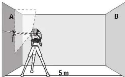
-Hacouete ro nacepot BO 6n3nHa ha sIOT A n octabete ro MepHnotypeDJa ce HnBeInpa.ObenexKeTe ja cpeINHata Ha ToKATA, Kaede nacepcknte nnHnCe BkpcTyBaat Ha sIOT (Touka I).

-CBpTeTe ro MeHnOtype1380°,ocTabeTe ro da ce HnBENnpa nO3HaueTe ja ToyKaTa Ha BkPctyBaBe Ha Nacepcknte nnHnHa cnpToHBnT sD B (Toyka II).
-IOCTaBETe ro MEPHnOT ypeI -6e3 da ro BpTHe -BO 6N3Ha Ha SNDOT B, BKnyTe ro n OCTaBete ro da ce HbEnpa.
-Noctabete ro MepHnot ypei no BnCnHa (co nmoow Ha CTaTHBOT Hn EBeHTyaHNO CO NIOIOrata), Taka ITO TOKkata Ha BkPCtYBaHe Ha Naacepckte IHHN ToHoo Ke ja IOROIN PpTeXoHNO O3HaueHATA ToKa II Ha SInOT B.
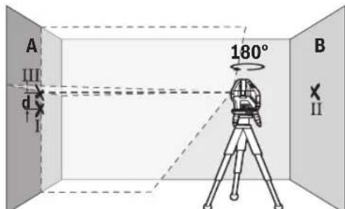
-Cbptete ro MePHNOT ype3 180°,6e3 da ja npomehite BnCnHATA.Hacouete ro Ha SIOT A,Taka wTO BePTNKaJIHATA nacepCKa IINHJa npOArA HN3BeKe O3NaHeHaToKaI.OCTaBeTe ro MePHNOT ypeD a ce HNBEnIPA H O3NaueTe je ToKaTa Ha BKpCTyBaHc Ha nacepCKte IINHN Ha SIOT A (ToKa III).
Pa3nKaTa dHaDbete O3HaueHToUckI I III Ha SIOA ro DaBa 0aKTHuKOTO OTCTanyBaHe OJ BNCnHaTa Ha MEPHNOTypeI.
HaMepHaJIHHJaOJ2×5m=10mMaKcHMaJIHOTo 03BOHeHOOTaTayBaHe H3HeCyBa:
10m×±0,2mm/m=±2mm.Pa3nKataMefTyouknteI INIcMee daH3NecyBa HajMHory 2 mm.
PpOBepKa Ha ToUHOCTa Ha HHBENHPaHe Ha XOpH3OHTaJIHATA JHHJia
3a npoBepka, noTpe6ha Bn e cno6oHa nOBpuHnHa oD OKony 5× 5m
-MoHTnpajTe ro MEPHnot ypeD BO cpeDnHa MEy SINOBHTe A n B ha potnpauka nnatopma (12) Ond. Ha CTaTMB (24), HnnoocTaBeTe ro Ha Ubpcta, paMaHa NpIOra. Bknyete ro MEPHnot ypeD BO pexKm Co aBTOMaTnka 3a HnBEnIpaHe. Bknyete ro XOpN3OHTaHHOT peKm n OCTabete MEPHnot ypeD da Ce HnBeJIIPA.
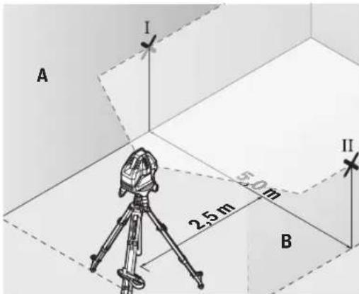
-Ha 2,5 m pactojarne od MepHnotypei. HaDbata sHa o3haue ter ja cpeinHata ha nacepckata nnHnja (toka I ha sNDOT A N TOKA II HA sNDOT B).

-NotaBeTe ro MEPHnOT ypei, CBPTeH 3a 180irc Ha 5 m pactoJaHHe n OCTaBeTe ro da Ce HbEnHa.
- Noctabete ro MEPHNOT ypeN NO BHCnHa (co nomou ha CTaHbOT nn EBEHTaIHO CO noDnOrata), Taka wTO CpeINHATA Ha NacepCKITE NHHN TOUHO Ke ja NorOIN npTeXoNDHO O3HaueHATA TOKA II Ha SInDT B.
Ha snoT A o6eNKeTe ja cpeHnata Ha nacepckata nnHja kako TocKa III (BepTKaIHO HAD INNO TOKATA I). - Pa3nKaTa d Ha DBeTe O3HaueHn TouKn I I I HA sHDoT A ro DaBa KaTnKoTo OTCaYBaHb e Ha MepHnO tpeD oI XOpN3OHTanata.
HaMephaIHHjaOg2×5m=10mroDabaMaKcHMaHHTO 03B0NEHOOTCTanyBaHe:
10m×±0,2mm/m=±2mm.Pa3nKata d Mefy ToKnte I I Icme da n3HecyBa HajmHory 2 mm.
PpOBepKa Ha ToUHOCTa Ha HnBENHPaHbeto Ha BePTKAnHaTAAHHJa
3a KOHTpONa notpe6eB H e OTBOP OJ BpataT, KaTe (Ha CBpCTa NoIOra) Ha ceKoJa CtpaHa OJ BpTaTa HMa MecTo OJ HajMaNKy 2,5 m.
-NotabeTe ro MEPHnotypeHa 2,5 m pactoJaHne oOTBOPoT Ha BpaTaTa Ha CBpCTa, paMaNoDnOra (He Ha potnpaKa nnatopma (12)nnnctaNB).BknyeTe ro
MepHnot ypeD BO pexHM CO aBtOMaTHKa 3a HnBeNHPaHe. Bknyte ro BEptKakHNoT pexHM CO BeptKakHa nacepcka IHHJa I N3paMHeTe ja KOH OTbOpOT Ha BpaTaTa. OctabeTe ro MepHnot ypeD da ce HnBeNIPA.
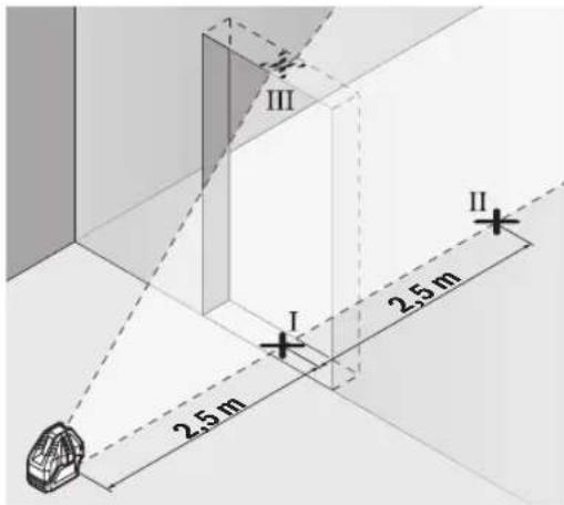
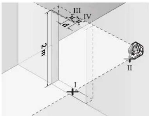
O3haute ja cpeinnata Ha Beptnkannata nacepcka IHHja Ha nooT od OTBOPOT Ha BpaTata (TOka I),Ha 5 m pactoJAHne OD npyraT a CtpaHa HA OTBOPOT OD BpaTata (TOka II), KaKo Hn HapHnOt paHa BA pTaT a OI OTBOPOT (TOka III).
-CBpTeTo MepHnOT ype3a 180° nNoctabete To Ha Dpyrata CtpaHa HA OTBOPoT Ha BpaTata dIpeKTHO 3ad Toukata II. OCTABeTe To MEPHnOT ypeD aC e HNBENIPA n HacoueTe ja BeptTKaHnA tNaIacePcKa IHHJta Taka WTO Hej3HNATA CpeHnA Ke NOMHyBa TOHOr HN3 TOOKITE I NII
-ObenexKeTe ja cpeHnHa Ta HaIacepckTa IHHJa Ha roHNOT pa6 Ha OTBOPoT Ha BpaTata KAKO ToKa IV.
PaJIHKaTa d Ha DBeTe O3HaueHn ToKn III IV ro daBa KaTHKoTo OCTaNyBaHe Ha MePHNOTypeOd BEPTHKaJIHHTe JINHH.
I3mepeTe ja BnCnHaTa HA OTBPOt OD BpTaTAt.
MaKcHMaHHTO O3B0NEHO OCTaNYBaHe ro npeMeTyBaTe Ha CnEHNOT HauH: IBOJHa BNCiHa Ho OTBOPoT Ha Bpata × 0,2mm / m
PnMep: PnBnCnHa Ha OTBpOHa BpaTaO 2 m MaKcMaHTo OCTaNyBaHe CMee Da N3HecyBa
64|MaKeDoHcKn
2× 2m× ± 0,2mm / m = ± 0,8mm .Tocknite III IV cmeat da nekaHajMHory 0,8 mm eHa oD npyra.
Cobetn npa6oTeheTo
3a o6eJyBaBe KOpHCTe ja cekoraw cpeiHaTah a nacepckata ToUKa OHN. Nacepckata HHHja.
TOnemHnHaTa Ha nacepckata ToKa Ond. HnpuHnTa Ha nacepckata nnHna je ce MeHyBa corNaCHO pactoJaHneTo.
Pa6oTebe co cenHa Ta6na 3a Iacepot
LcnHata Tabla 3a nacepot (22) ja nooobpyBa BnInBocTa Ha IacepcknoT 3paK npH HeNoBOJHn ycNoBn rOJeMn pactoJahna.
PeΦIeKTHpaUkTaNoBpUHaHaζEHaTaTa6Na Ha IacepoT (22) ja nOobpyBa BVnINBOCTa Ha IacepcKaTa IHHJa, Hn3 TpaHCnapeHTHaTo NOBpUHa Iacepckata IHHJa e BVnIBaH oD 3aHaTa CtpaHa HaζEHaTa Ta6Na Ha IacepoT.
Pa6oTebe co cTaTHB (onpema) (BnHcNkkaF)
CtANBOT OBO3MOKyBa Cta6HnHa MEPHa NODIora WTO MOKe Da Ce NOdecyBa No BnCnHa. 3a MoNTaxKa Ha MEPHNOT ypeD Ha CTAnB NOCTaBeTe Ro MEPHNOT ypeD Ha potNpaKkata INaTΦopMa (12).
MoTAtKa Ha 5/8"-CTaTHB: NocTaBeTe ja potnpaKata nlaTΦopMa co 5/8"-PnHcTaHa cTAbHToB (9) Ha HABoJOT Ha 5/8"-CTaTHB (24) nHn Ha o6uHcHpadeKeH cTAHB.
3aucpcte ja potnapkaTnpatopma co 3abptka 3aФHKcnpaHe Ha CTATHBOT.
MoHTaKaHa1/4"-CTaTbB(BnDnCnkaF):HabPteTe ro aadantepo3a ctaTbOT(18)(onpema)Bo5/8"-npnpaHa ctaTbOT(9)Ha potHpauKaTaNtΦopMa. NocTaBeTe ro aadantepo3a ctaTbOTco1/4"-npnФaTHa ctaTbOT HaHOBJOT Ha1/4"-CTaTbB(19)NnHaOBuH eTO ctaTbB. 3aUbPcTeTe ro aadantepo3a ctaTbOT co3abptka3a fHKcnpaHe Ha ctaTbOT.
Ipybo ceHTnpajTe ro ctaHBOT, nped da ro BKnyHtMePHNOTypei.
Nacepcn 3aunTHn ouHa (onpema)
Nacepckte 3aHTTHO Ounna ja qnITPnpaaT OKONHata CBETINHa. Ha ToJ HauHH CBeTNO TO HA Nacepot n3rIeJa NOCBETIO 3a OKOTO.
He Hn Kopnctete Nacepcknte 3aHTTHN OUYNA (DOnONHnTeHaOpema) KAKo 3aHTTHN OUYNA. Nacepcknte 3aHTTHN OUYNA cnjxkat 3a noD6p0 paCno3HaBaHbHe Ha NacepcknO TpaK; cenaK, Tne He WHTNaT od NacepckOTo 3paueHe.
He HN KOpNCTeTe NacepCKNTe 3aHTTHN OuHna (DOnONHnTEHa ONPema) KaKo OUYHa 3a COHc EHN NaK BO COO6paKaJOT. NacepCKNTe OUYHa He DaBaAT UENoCHA UV-3aHTNa I rO HAManyBaat npen03HaBaeTo Ha 6oH.
PpHmepn 3a pa6oTa (BnD nCnKn B-E)
PpMepn 3a MoKHOCTHe Na pImeHa Ma MePNOTypeKe HajTe Ha rpaHcNKeTc TpaHnU.
OdpKyBaHe n cepBnC
OdpxByBaBe n uHCTeHe
Ioctojano OndjyBajTe ja NcTotaHa MePHNOT ypeJ. He ro notonyBajTe MePHNOT ypeJ BO BODa Hn DpyrTeuHOCTH.
I36pnueTe rHneHCTOTnTE CO BnaXHa MeKa Kpna. He KopncTeTe CpeDCTBa 3a NHTeHe HnN paTbOpn.
PeIOBHO UHCTeTe rN IOBpUHHHTe OKOyI H3Je3HHOT OTBOP Ha Iacepot N npTuA BHHMaBajTe HA BnAKeHuaTa.
MepHnOT ypeK cnAaHnpajTe ro n TpaHCnOpTnpajTe ro cAmo BO 3aATHTHaTa YaHtA (23).
Bo cnyaj da tpe6a da ce nonpabn, npaTe ro mepHnot ypei BO 3auTHTata TaHa (23).
CepBncha cnjx6a n cobet npn kOpncTebe
CepBnchata Cnyk6a Ke OndroBOpn Ha BaWnte npaHaBa BO Bpcka co nonpaBkata N odpxyBaHeto Ha BaWnO TpoN3BOD KaKo n pe3epBNHTe DeIOBn. O3NaKn 3a EKCnIoo3nJa HnHΦopMaun 3a pe3epBNHTe DeIOBn HcTo TaKa Ke HajTe Ha: www.bosch-pt.com
TMMOT 3a COBetyBaBe npn KopncTeHe Ha Bosch Ke BV NOMORHE DOKOLKY IMate npaHaHa 3a HauHte npon3BOOn nOpema.
3a CHTe npaaHbHa HapaKHa pe3epBn Denobn,Be MoIIme HabeTe ro 10-ncfpeHHOT 6poj OcneuNkauHata IIOUka Ha npou3BODOT.
Cebepha MaKeDoHnja
Д.Д.Енковский
CabaKobayek47Hb,6poj3 1000 Ckonje
E-nowta: dimce.dincev@servis-bosch.mk
HHTepHer: www.servis-bosch.mk
TeJ./daKc:02/2467610
Mo6.:070595888
D.I.T.Y "POJKA"
JaHnIyKpOBcKn 66;T.IA ABTOKOMaHaJNa IOKaN 69 1000 CkONje
E-nowa: servisrojka@yahoo.com
Ten: +389 2 3174-303
Mo6: +389 70 388-520, -530
DOnonHnTeHH aDpeCN Ha cepBnCn MoKe da HajTe NOd:
www.bosch-pt.com/serviceaddresses
OtctpaHyBaBe
Mepnte ypeiOnpemata n am6anaxne Tpe6a da ce OTCTpaHaT Ha ekOLOoKn PnpΦaTnB HauHH.

He nФрпаTe Мернite УрEDи 6aTePnHTe BO DOMaHHaT a KaHt a OtnaOuNi!
Cama 3a 3emjnte oEY:
Cnopeed ebponckata dnpkeTnBa 2012/19/EU MEPHnTe ypeH nTO ce BOH ynoTppe6a n depeKTHnTe mnn NcKOpNCteHnTe 6aTeepn CnopeD npkeTnBaTa 2006/66/EC
Mopa OndenHO da ce cobepat n da ce peuknnpaat 3a NOBTOPA ynotpe6a.
Srpski
aill osc lccgagal aulll
jag. 1
Lgubclla 9 wlll oos Lgol
jai
aaii aaij oii
gjrgsIbssI jIw g iJgai
GJXgJXJUaHJUsWJJUULeWU
jU|EwUJoo
日 L _ 山 山 ( 出 ; 山 ) 山 山
aJJI-1JJU 0jlaS g
aJgJoIaIlaJUJJuJIa
jdlalallosaasaa
jgljjuuJLc
olaiw ljc jua821 go uuugo uuaaia
aJlJIgBglc ablaall j
wJoo
wllddg
aJg jUg elwaiacww
aag jgsjpal
abj j0j0gjj
gIJIgJgJgJgJgJgJgJgJgJgJgJgJgJgJgJgJgJgJgJgJgJgJgJgJgJgJgJgJgJgJgJgJgJgJgJgJgJgJgJgJgJgJgJgJgJgJgJgJgJgJg
jg.(gJALU LALIe Jg juill eii
0jg 0j00
72
| GLL 3-15X | jbjjj |
| jbjj(jɔjɔjɔj)IP54 | a |
| (jɔjɔjɔjɔj) | (üjjj |
gjw joo jao jao g (A
2011 (B)
25-20 1a 1c
gjll jgl ogsall gajll jujl (D
gjll lgl (jw) auiu gai gl auiuabaiall
auii jg s aia jg s w jg , ojjl jui
aui jg ooi uaiu uaiu . (ouiu uaiu uaiu
aui jayu cuiai q uiuy uuiy d yjull
uiu uui y uui y uuiu uuiu uuiu uuiu (E
uuiu uuiu uuiu uuiu uuiu uuiu uuiu
0jIgJJI aaioi go lao jgio (F
a>gl Jc4)Jusll jgj,200g,laill oae
#
JUJIbIJI JUsWJU
U 10000000000000000000000000000000000000000000
(2) (3) 11111111111111111111111111111111111111111
Jpaai.ogll mai g Uylll Js yau pao .Ojdlg egill mai no Uylllpl
pse ci wll ooc no ujll Eji
JnSsaUJIaJI.ajjLgsswI
ojai jai jai a lae lal qian g jaoi .wol ooc Jauu uagb
jglJl aiaJl go JaaJI
(A ojgall jil)
0scj1s(12)0jlgAaiiaIg jc nksa ujsaoaiabai 360 aagj wuall qjjllbgaas kssaaag.
Solll abagg wlll lsswlllaab (D-C galll bil)
gdiI jaiI jw go Jasll
JJJ JJJ JJJ JJJ JJJ JJJ JJJ JJJ JJJ JJJ JJJ JJJ JJJ JJJ JJJ JJJ JJJ JJJ JJJ JJJ JJJ JJJ JJJ JJJ JJJ JJJ JJJ JJJ JJJ JJJ JJJ JJJ JJJ JJJ JJJ JJJ JJJ JJJ JJJ JJJ JJJ JJJ JJJ JJJ JJJ JJJ JJJ JJJ JJJ JJJ JJJ
山
山
aawgagbJU.
j8 4g jJlJU
jol jc ysgolll jll ba aaiu jauy qg - 111105261gc (I aboill) uall aig aalil Ic lag (II aboill) uall aiaq joo .(III aboill) uall aiaoy agloll

wJlI Ic 180 Jdaw wJall oJ
E .ll abai I calo oWu wU aq jn Ja
ba dgg li IgwiBauogai wJall
I jibai Ioo adaio Jo y Bgol Jjll
2 1g 1 jibai 1 d
a91I bJI aGWI I aJ
gdua aalaa 15x5.0 -juaaall
g(12) 0jlgll aaiil lgc B g A jlll alal
aajl lgc leao g (24) pglal llll jolal
g wlll osc lsswyy q. agwuog aui
uowyy qg. agwlll ao go llwll aab
oic lgwl bawp g o911 wlll aab
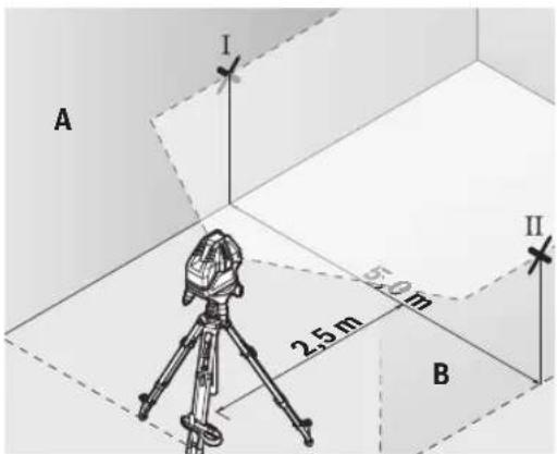
j0 2,5 jlc jull bcaiaio juaai p - (a) abai) uJdL Lc uJall oC .(B Jdll Uc II abaiIg A JdJI
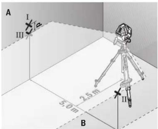
180 5
gai jg 5
aaguiy gai jgi 5
jai abwgl) waii oegai ay gwi y
sic laia lo gog u gai gai y
aay jll baaiau y (ogai
B jdl lce uauu g ui ll abail
A jdl lcle iiais jull baaiau y
.(ugac i aboiil gg)
Ic niaolall g iunbail nn d gai ksi
ggl no waii suea aia A
jUbiS (gj) jUu A g jUoi
aJlI []jU jLg
aolll aLoJjJlU aogj oJai gai 2.ajjgjoll
JdJI Jai jil los aiaowaii (gag
.1gJJI jai JLC
(E-BgJJIjai)
yLwaiol oocolssaiW alotle
abubuillgwhll
aJg aJal
cuiIg aui
wulai oac aglai lc lais kala
joo uue gai juLg wuaJoo uus
U
- dubg djuu waaa aabg abwgl gawg
a do slgo g lubu slgo o sui
Jsu jui gja daig sic ggbwll aolkai
auii auiiui gaii
Robert Bosch Morocco SARL
g joo ojll 53
LJ1J20300
+212529314327:
sav.outillage@ma.bosch.com:
:aaal jglic no jall
www.bosch-pt.com/serviceaddresses
auijseJ 10
g gglg wll scc oalil
jIJL qaiuui jyub ic ailll lcl alalaoa
aill 0y yll
Jn JnJnJnJnJnJnJnJnJnJnJnJnJnJnJnJnJnJnJnJnJnJnJnJnJnJnJnJnJnJnJnJnJnJnJnJnJnJnJnJnJnJnJnJnJnJnJnJnJnJnJn
!aJjJlJI JlJI

-aaJJI aJJI JcJJ abaiU uI Uc UUaioIV.
-(gJUd uabu
JUSS UGLaU Uuus
JgL (sH) "On" Cgo J7
jui jL (sI) "On" Cggo JU (JgSIL Coo g jilw .
jw jj w w dLj y oJ Jj Jj .gW
(1)glgjdoaiojla jIbS.
golal 1j jglg qg a laa o n g g u lga jgs alg jl ski jjjg
/ωg jSjS oJd jIj Js gwola Cg jsiw .jU "Off" caggo J(7) wga
golg. gw y jwj (15) cagog .gwh JgJdJdJ
JU JI JI JI JI JI JI JI JI JI JI JI JI JI JI JI JI JI JI JI JI JI JI JI JI JI JI JI JI JI JI JI JI JI JI JI JI JI JI JI JI JI JI JI JI JI JI JI JI JI JI J1
45golajjglj 45
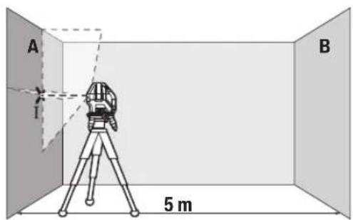
g g A Jg Sjj jj 1 s 1s dai jy .g w jj s oj w jj 1 coiie iis go jlg bgsbai 1. (aai) ss
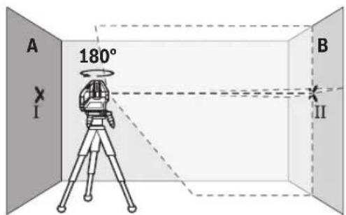
180°JdQU JgSjJlJj- 1gJjI jIbai gabai gswjIj SjBj IaBai BJia jIgSjJ - wJgJg - JgSjJlJj- 1jJJJgJgJgJgB
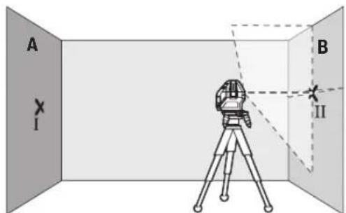
sai pabi (gjgl jbj j1 (sjjil jj - (jj jui ju y u ayw Sos a) abai (sgj lao jj logba eblai abai li .Bjgsj 0sw (sjla
Jg jgbj jj jj j j j j j j j j j j j j j j j j j j j j j j j j j j j j j j j j j j j j j j j j j j j j j j j j j j
JL 31 J
. 000000000000000000000000000000000000000000000000000000000000000000000000000000
guljUJL gol/ugjLs,glquLgQ)7(
" Cusagogo OnJao jsiaw .si Jgjlu)14(bgsgws
G Saui duiuui ciwu g Saaoo jgdo (SjJ
Jgac glogil jIj Ig sily Jg Jls pKim
dilJI JsOjSIIJjIjIgJLoLw. gW Lo
Jg Cwli Os SgJU Jyds dCsw
du Cwgi sigw oji jjJJu Isgj.
.
jIJIJIJU
Jocg s o jisj jolge
ggs.1sJls bbs 1slo juui jnuiu JJJg sUgl GxLb a 5la 1s0 dai .Sis
juiu juy jusj J Loo y daa dai j1 0000 oji si jy uayu, cwi Jdo 1w g jI g qis wai dy aw syg jLsoi
JLJSSbW
OswdBgjoUjigUjls
Ccuuog(yuwgljsuJsi
Egwhjl jglio uo d. sigw bs jg
Sis Jus Ljip Cds
g jj bjj g elal jl d jolg a. jis j s gac jj j j j j j j j j j j j j j j j j j j j j j j j j j j j j j j j j j j j j j j j j j j j j j j j j j j j j j j j j j j
JgBosch. Js Hasi
GgI bEaJj CJ JuiS
5 5j jj jj j j j j j j j j j j j j j j j j j j j j j j j j j j j j j j j j j j j j j j j j j j j j j j j j j j j j j j j j j j j j j j j j j j j j j j j j j j j j j j j j j j j j j j j j j j j j j jj
82|w
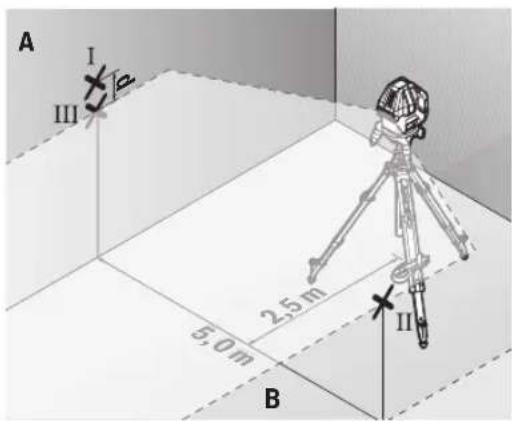
180° JJgSjol jIj 5dolg
sabij g elaj jbl sjol jIj 1
(1j jj ljl aagw Sos d) abai sgj jj bawg abai li B jgsj jj oW sJxioLc
III abai ngic ay jj la bawg A jgs j
.5i (aai jy L (aai jy sgc)
jI SsS oJ il jI JI 0g2g2gA
.oooo
jL25u2x5m=10m
LwIμ
dbai d 10m x ±0,2 mm/m = ±2 mm
. 山山山山山山山山山山山山山山山山山山山 2 Cj j JJ WU I1I g I L
gac bjjj jiiSogai
jg jgbljjglgajdjg jgsgbw gaa
jlaaawduwuldgabuljugss
Sd Slaawl jg s Jaaa
Ia 15ySjOjJiljI JgJog
23.
csjI jSjJljljLjUo
23.
jUjuaLggluoglo
Josj oJds laW giw d juio lo
.1s 1g a wu uo b g uogw
LabgDlogjoIcIbIgSsduStgauo
:duu yj slajj J L Ss
www.bosch-pt.com
Juiuua du guiuogbschdu uulss
Lg Lalao g 0gdo oJds laaw
.
la,ysu bbaawg g uw dg s
j0jaw10jIgJw
.
wJg-1jWgBcKw-1|g
Uglulu,olssugwulus,Sig ulso
jlaow, jylo jlaiaIw3. gww aub
j1994834571
:12039000+9821
aolj jjloa jLw
www.bosch-pt.com/serviceaddresses
olssjS jIa oJ jI
a yu Lg aun g caldo ojil jj
g jla oj jl cwwj bao bao ly wliog
.ugw 乌j
JlI LgSjI gSjI jil SjI JjI
!jjilui jilu jdu j

:glj dJl j gac s JgS Jb
o laaiw lla g diq sui jil il sljli
gJgJUaJIgWgJg doli jI gBjSJJ
2012/19/EUwluuJgJgJgJg
Lgjgjgjgjiuu12006/66/EC
.igw[5]ggoaowj bdo ly cwwliio


- GLL 3-15 X Professional
- English
- Safety Instructions
- Product Description and Specifications
- Intended Use
- Product Features
- Line laser GLL 3-15 X
- Assembly
- Inserting/changing the batteries
- Working with the Rotating Platform (see figure A)
- Operation
- Starting Operation
- Switching On/Off
- Deactivating the automatic shut-off function
- Operating Modes
- Horizontal mode (see figure B)
- Vertical mode and plumb point (see figures C-D)
- Automatic Levelling
- Working with automatic levelling
- Working with the pendulum lock
- Accuracy Check of the Measuring Tool
- Influences on Accuracy
- Checking the Height Accuracy of the Horizontal Line
- Checking the Level Accuracy of the Horizontal Line
- 10|English
- Checking the Level Accuracy of the Vertical Line
- Working Advice
- Working with the Laser Target Plate
- Working with the Tripod (Accessory) (see figure F)
- Laser Goggles (Accessory)
- Example applications (see figures B-E)
- Maintenance and Service
- Maintenance and Cleaning
- After-Sales Service and Application Service
- Great Britain
- You can find further service addresses at:
- Disposal
- Only for EU countries:
- Français
- Eliminación
- Eliminação
- Tasfiye
- Cpok cnyx6bH3dennn
- Ipeueenb KpntHuecknx OTka3OB H OwH6OuHbIe DeiCTBn IepcoHaHa HIN NOnb3oBaTeN
- | Pycckn
- Kpntepnn npedeBhbix coctoHHn
- Xpahene
- TpaHcnpToPbovBa
- Yka3aHnnoTexHnke6e30nacchoCTn
- OnncanHe npoDyKta n ycnyr
- PpHMeHeHnNoHa3NaeHHo
- H306paXeHHbIe COCTaBHeIy aACTn
- BkJIIOUeHHe MHCTpymEHa
- BkHoueHne/BbIKHoueHne
- DeakTHBaunrABOMaTHueCKOroBbIKIOUeHHN
- Pexmmbl pa60tbl
- Topn3oHTaIbHbI pexHM pa6Otbl (cm.pnc.B)
- BepTKaJIbHbI pEXHM pa6OtBI H TOUKN OTBeCa (CM.pHC.C-D)
- ABTomathueckoe HmBemnpoBaHne
- Pa6ota c aBTOMaTHueCKHM HNBeJIHPOBaHHem
- Pa60Ta c 6nOKHPOBkoMaTHNka
- KoHTpOJIb TOUHOCTn H3MePHTeJIbHOrO HHCTpyMEnTa
- ΦaKTOpbl, BnHryoUne Ha ToUHOcTb
- PpOBepKaToOHocTHTopn3oHTaNbHOJINHHN NO BbICote
- | Pycckn
- PpOBepKa TouHocTH HnBeHnPoBaHHaTropn3oHTaBHOH
- PpOBepKa TOpHocTn HNBENHpOBAHHaBepTKKaIbHOJHHH
- Yka3aHnno npimHeHHIO
- Pa60Tb C BN3HpHoM MapKoI
- Pa6oTa co wTaTHBOM (npHnAdnEeXHOCTb) (cm.pnc.F)
- OuKnIpa60TbIcna3epHbIM HhCTpyMeHTOM (npHaadNexKHOCTb)
- PnHmepbI BO3MOXhBIX BnOBo pa6oTbI (cm.pnc.B-E)
- Texo6cnyKbHaHne n cepBnC
- Texo6cnyxHBaHne n ouhctka
- CepBnKoHcyNbTHpObaHne NO BOpocam npMeHeHn
- Ди рснona: Pocchna, Beapycb, KaazxcTан, Ykpannha
- Poccn
- DOnonHnTeNbHbIe apeca cepBnchbIX ceHTPOB Bbl HauDeTe no CcbInke:
- Ytlnn3aun
- Po6oTa 3 NOBOPOTHOI NnATΦOPMOIO (INB.MaI.A)
- Po6ota
- Noataokpo60tn
- BmKaHHBmKHaHH
- DeakTHBaui cyHKuABTOMaTHUHO BHMKHeHHA
- Pexmm po60Tu
- Topn30HTaBHHpeXmpo6OTn(duB.man.B)
- BepTKaJIbHHn peKHM Ta TOUka BnCKa (JHb. MaI. C-D)
- AbTomatnuhe HIBENIOBAHNA
- P6oTa y pexKMI aBtOMaTHuHOrO HIBeIIOBaHH
- Po6ota 3 6nOKyBaHHMaTTHnKa
- Ipebipka TouHocti BmipobalbHoro IHctpymenta
- AkpTOpH, 0o BnNbaHoiB Ha ToHicThb
- Ipebipka touhocti ropn3oHTanboHIO nHn no Bcotti
- Ipebpka ToHocti HibenbAHnroPn3oHTaBHOi nii Inepebpkn NoTpi6Ha Binha DInrKa np6n.5x5M
- 50|YkpaHcbKa
- Tepebipka ToHocI HIEBIOBAHHA BEPTKANbHOI NII
- Bka3iBKn 0oDo pO60Tu
- Po60TH 3 Bi3npho1o Mapko1o
- Po6ota 3i wTaTHBOM (Pnnaad) (mB. Man. F)
- Okynprn dny po60TH 3 na3epom (npnaad)
- Ppknna npo6to (nB. Man. B-E)
- Texhuihe 06cnyrobyBaHHaicepBic
- Texhihe 06cnyroByaHHia ouhueHHA
- Cepbic i koncynbtaqii 3 nHTaHb 3actocybaHHA
- YkpaHa
- Ytunizaia
- Jnne dna KpaHcC:
- Ka3ak
- Eypa3nna 3KoHOMnKaIbIK OdaftbHa (KeDen OdaftbHa) Mywe MemLeKeTtep aymarfbHda KOnDaHbIaIbI
- Ohimdi nai danany MEP3imi
- Kb3METKeHemeCe NaDanaHyBbHbN KATENIkTepi MeiTeH bIyFc6entepinT3imi
- Wekri kyy 6gnrinepi
- 52|Ka3ak
- Kb3met Kepcety Tpy MeH Xniniri
- CaKray
- TacbImanday
- Kayinci3ik HycKaynapbI
- ΘHIM XKHe KyaT CnNaTTaMaCbI
- Taraihany60bHwaKoJdany
- KopceTinren Kypamdaac 6nweKeTep
- AinHMa nIaTΦopMaMeH Kymbic icTey (ACypetIH kapaHb13)
- 54|Ka3aK
- PaindanaHy
- PaiDanaHyFa eHdpy
- Kocy/ewipy
- Θwipy aBTOMaTHKacbih aXbipaty
- PaiDanaHy typlepi
- KoIeHeH JxMbIc pexkmi (B cypetin kapaHb3)
- Tik xymbic pexmioxene nepneHnkynp Ta6aHbI (C-D cypertepin kapaht3)
- HbEnnpey abTomakacbi
- Hbennpney abTomakacbIme Hxmbic icTey
- MaTHMKTi 6yFaTTay TetirimEn Jxymbcictey
- Onwey KypanbHbH dAnirir TeKcepy
- Дэдik acepnepi
- KoIeHeH cb3bIKtbH 6nIKtik dAndiirin Tekcepy
- 56|Ka3aK
- KoIeHeH cb3bIKtbH HnBEnHpNey dAnirin Tekcepy
- Tik cb3biktbH HbEnhpney dndirin Tekepeiia
- PaindanaHyckaynapbI
- Naep HbicaHdbik TaKTabiH naIaIaIaHy
- UtaTHBneHxMbic icTey (KepeK-KapaK) (FCypetIN KapaHbla3)
- Ia3ep Kepy Ke3inipiri (kepek-kaapak)
- Kadere kapaTy
- Tek KaHa EO endepi ywH:
- MaKeDoHcKn
- Be36eHocnHaNoMeHH
- Onnc Ha npoH3BOJTo n nepOpMaHCnTe
- YnOte6a co cooDbetHa HameHa
- Hnyctpaunja ha KOMnOHeHTN
- CtBaBHe/MeHyBaBe Ha 6aTePn
- Pa6oTehe co potnpaKa nlaTΦopMa (BnuH cnka A)
- Ynotpe6a
- CtabaheBoynotpe6a
- BknyBaBe/ncknyyBaBe
- DeakTNBnPaHe Ha aBTOMaTHKaTa 3a NCKnyyBaHBe
- Haunna pa6ota
- Xopn3oHTaneH peKmBnCnka B)
- BepTKanenpeKmHToKaHaBePTKana (BnDcnKnC-D)
- ABTomatka 3a HnBelenpaBe
- Pa6oTeHe co aBTOMaTHKa 3a HnBEnHpaHe
- Pa6oTa co ocunlaTopna 6noka
- KoHTpona Ha ToUHocTa Ha MepHnO Type
- BnnaHnaHaToHocTa
- | MaKeDoHcKn
- PpOBepKa Ha ToUHOCTa Ha BNCnHaTa Ha XOpH3OHTaIIHaTa nnHnja
- PpOBepKa Ha ToUHOCTa Ha HHBENHPaHe Ha XOpH3OHTaJIHATA JHHJia
- PpOBepKa Ha ToUHOCTa Ha HnBENHPaHbeto Ha BePTKAnHaTAAHHJa
- 64|MaKeDoHcKn
- Cobetn npa6oTeheTo
- Pa6oTebe co cenHa Ta6na 3a Iacepot
- Pa6oTebe co cTaTHB (onpema) (BnHcNkkaF)
- Nacepcn 3aunTHn ouHa (onpema)
- PpHmepn 3a pa6oTa (BnD nCnKn B-E)
- OdpKyBaHe n cepBnC
- OdpxByBaBe n uHCTeHe
- CepBncha cnjx6a n cobet npn kOpncTebe
- Cebepha MaKeDoHnja
- DOnonHnTeHH aDpeCN Ha cepBnCn MoKe da HajTe NOd:
- OtctpaHyBaBe
- Cama 3a 3emjnte oEY:
- Srpski
- #
- JUJIbIJI JUsWJU
- jglJl aiaJl go JaaJI
- (A ojgall jil)
- Solll abagg wlll lsswlllaab (D-C galll bil)
- gdiI jaiI jw go Jasll
- 山
- a91I bJI aGWI I aJ
- aJg aJal
- cuiIg aui
- auijseJ 10
- jIJIJIJU
- Jocg s o jisj jolge
- GgI bEaJj CJ JuiS
- jUjuaLggluoglo
- olssjS jIa oJ jI
Brand : BOSCH
Model : GLL 315 X Professional
Category : Laser pointer