
DHR400ZKU - Hammer MAKITA - Free user manual and instructions
Find the device manual for free DHR400ZKU MAKITA in PDF.

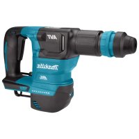
| Product type | Cordless rotary hammer |
| Brand | Makita |
| Model | DHR400ZKU |
| Drilling capacity (carbide-tipped bit) | 40 mm |
| Drilling capacity (core bit) | 105 mm |
| No-load speed | 250 – 500 rpm |
| Impact rate | 1,450 – 2,900 min⁻¹ |
| Overall length | 473 mm |
| Rated voltage | 36 V DC |
| Net weight (depending on battery) | 7.3 – 8.1 kg |
| Compatible batteries | BL1815N, BL1820B, BL1830B, BL1840B, BL1850B, BL1860B |
| Compatible chargers | DC18RC, DC18RD, DC18RE, DC18SD, DC18SE, DC18SF, DC18SH, DC18WC |
| Sound pressure level (L_pA) | 91 dB(A) |
| Sound power level (L_WA) | 102 dB(A) |
| Vibrations – hammer drilling in concrete | 4.7 m/s² (K=1.5 m/s²) |
| Vibrations – chiseling (side handle) | 4.6 m/s² (K=1.5 m/s²) |
| Vibrations – chiseling (side grip) | 4.9 m/s² (K=1.5 m/s²) |
| Operating modes | Rotation with hammering, hammering only, chiseling |
| Electronic functions | Constant speed control, Active response sensing technology, Torque limiter |
| Lighting | Front LED light |
| Wireless activation function | Yes (with optional wireless connector) |
| Supplied accessories | Side handle, side grip, depth gauge, transport case |
| Maintenance | Clean with a dry cloth; repairs by authorized center |
Frequently Asked Questions - DHR400ZKU MAKITA
User questions about DHR400ZKU MAKITA
0 question about this device. Answer the ones you know or ask your own.
Ask a new question about this device
Download the instructions for your Hammer in PDF format for free! Find your manual DHR400ZKU - MAKITA and take your electronic device back in hand. On this page are published all the documents necessary for the use of your device. DHR400ZKU by MAKITA.
USER MANUAL DHR400ZKU MAKITA
- Due to our continuing program of research and development, the specifications herein are subject to change without notice.
- Specifications may differ from country to country.
The weight may differ depending on the attachment(s), including the battery cartridge. The lightest and heaviest combination, according to EPTA-Procedure 01/2014, are shown in the table.
Applicable battery cartridge and charger
| Battery cartridge BL1815N / BL1820B / BL1830B / BL1840B / BL | 850B / BL1860B |
| Charger DC18RC / DC18RD / DC18RE / DC18SD / DC18SE / DC1 | 8SF / DC18SH / DC18WC |
- Some of the battery cartridges and chargers listed above may not be available depending on your region of residence.
WARNING: Only use the battery cartridges and chargers listed above. Use of any other battery cartridges and chargers may cause injury and/or fire.
Recommended cord connected power source
| Battery adapter BAP182 | |
| Cord connected battery pack | BL36120A |
| Portable power pack | PDC01 / PDC1200 |
The cord connected power source(s) listed above may not be available depending on your region of residence.
Before using the cord connected power source, read instruction and cautionary markings on them.
Intended use
The tool is intended for hammer drilling and drilling in brick, concrete and stone as well as for chiselling work.
Noise
The typical A-weighted noise level determined according to EN62841-2-6:
Sound pressure level (L_pA):91 dB (A)
Sound power level (L_WA):102dB (A)
Uncertainty (K): 3 dB (A)
NOTE: The declared noise emission value(s) has been measured in accordance with a standard test method and may be used for comparing one tool with another.
NOTE: The declared noise emission value(s) may also be used in a preliminary assessment of exposure.
WARNING: Wear ear protection.
WARNING: The noise emission during actual use of the power tool can differ from the declared value(s) depending on the ways in which the tool is used especially what kind of workpiece is processed.
WARNING: Be sure to identify safety measures to protect the operator that are based on an estimation of exposure in the actual conditions of use (taking account of all parts of the operating cycle such as the times when the tool is switched off and when it is running idle in addition to the trigger time).
Vibration
The vibration total value (tri-axial vector sum) determined according to EN62841-2-6:
Work mode: hammer drilling into concrete
Vibration emission (a_h,HD) .. 4.7~m / s^2
Uncertainty (K): 1.5m / s^2
Work mode: chiselling function with side grip
Vibration emission (a_h,Cheq) .. 4.6~m / s^2
Uncertainty (K): 1.5m / s^2
Work mode: chiselling function with side handle
Vibration emission (a_h,Chq) .. 4.9~m / s^2
Uncertainty (K): 1.5m / s^2
NOTE: The declared vibration total value(s) has been measured in accordance with a standard test method and may be used for comparing one tool with another.
NOTE: The declared vibration total value(s) may also be used in a preliminary assessment of exposure.
WARNING: The vibration emission during actual use of the power tool can differ from the declared value(s) depending on the ways in which the tool is used especially what kind of workpiece is processed.
WARNING: Be sure to identify safety measures to protect the operator that are based on an estimation of exposure in the actual conditions of use (taking account of all parts of the operating cycle such as the times when the tool is switched off and when it is running idle in addition to the trigger time).
EC Declaration of Conformity
For European countries only
The EC declaration of conformity is included as Annex A to this instruction manual.
SAFETYWARNINGS
General power tool safety warnings
WARNING: Read all safety warnings, instructions, illustrations and specifications provided with this power tool. Failure to follow all instructions listed below may result in electric shock, fire and/or serious injury.
Save all warnings and instructions for future reference.
The term "power tool" in the warnings refers to your mains-operated (corded) power tool or battery-operated (cordless) power tool.
CORDLESS ROTARY HAMMER SAFETYWARNINGS
Safety instructions for all operations
- Wear ear protectors. Exposure to noise can cause hearing loss.
- Use auxiliary handle(s), if supplied with the tool. Loss of control can cause personal injury.
- Hold the power tool by insulated gripping surfaces, when performing an operation where the cutting accessory may contact hidden wiring. Cutting accessory contacting a "live" wire may make exposed metal parts of the power tool "live" and could give the operator an electric shock.
Safety instructions when using long drill bits with rotary hammers
- Always start drilling at low speed and with the bit tip in contact with the workpiece. At higher speeds, the bit is likely to bend if allowed to rotate freely without contacting the workpiece, resulting in personal injury.
- Apply pressure only in direct line with the bit and do not apply excessive pressure. Bits can bend, causing breakage or loss of control, resulting in personal injury.
Additional safety warnings
- Wear a hard hat (safety helmet), safety glasses and/or face shield. Ordinary eye or sun glasses are NOT safety glasses. It is also highly recommended that you wear a dust mask and thickly padded gloves.
- Be sure the bit is secured in place before operation.
- Under normal operation, the tool is designed to produce vibration. The screws can come loose easily, causing a breakdown or accident. Check tightness of screws carefully before operation.
- In cold weather or when the tool has not been used for a long time, let the tool warm up for a while by operating it under no load. This will loosen up the lubrication. Without proper warm-up, hammering operation is difficult.
- Always be sure you have a firm footing. Be sure no one is below when using the tool in high locations.
- Hold the tool firmly with both hands.
- Keep hands away from moving parts.
- Do not leave the tool running. Operate the tool only when hand-held.
- Do not point the tool at any one in the area when operating. The bit could fly out and injure someone seriously.
- Do not touch the bit, parts close to the bit, or workpiece immediately after operation; they may be extremely hot and could burn your skin.
- Some material contains chemicals which may be toxic. Take caution to prevent dust inhalation and skin contact. Follow material supplier safety data.
- Always be sure that the tool is switched off and the battery cartridge and the bit are removed before handing the tool to other person.
- Before operation, make sure that there is no buried object such as electric pipe, water pipe or gas pipe in the working area. Otherwise, the drill bit/chisel may touch them, resulting an electric shock, electrical leakage or gas leak.
- Do not operate the tool at no-load unnecessarily.
SAVE THESE INSTRUCTIONS.
WARNING: DO NOT let comfort or familiarity with product (gained from repeated use) replace strict adherence to safety rules for the subject product. MISUSE or failure to follow the safety rules stated in this instruction manual may cause serious personal injury.
Important safety instructions for battery cartridge
- Before using battery cartridge, read all instructions and cautionary markings on (1) battery charger, (2) battery, and (3) product using battery.
- Do not disassemble or tamper with the battery cartridge. It may result in a fire, excessive heat, or explosion.
- If operating time has become excessively shorter, stop operating immediately. It may result in a risk of overheating, possible burns and even an explosion.
- If electrolyte gets into your eyes, rinse them out with clear water and seek medical attention right away. It may result in loss of your eyesight.
- Do not short the battery cartridge:
(1) Do not touch the terminals with any conductive material.
(2) Avoid storing battery cartridge in a container with other metal objects such as nails, coins, etc.
(3) Do not expose battery cartridge to water or rain. A battery short can cause a large current flow, overheating, possible burns and even a breakdown.
- Do not store and use the tool and battery cartridge in locations where the temperature may reach or exceed 50^ (122^) .
- Do not incinerate the battery cartridge even if it is severely damaged or is completely worn out. The battery cartridge can explode in a fire.
- Do not nail, cut, crush, throw, drop the battery cartridge, or hit against a hard object to the battery cartridge. Such conduct may result in a fire, excessive heat, or explosion.
- Do not use a damaged battery.
- The contained lithium-ion batteries are subject to the Dangerous Goods Legislation requirements.
For commercial transports e.g. by third parties, forwarding agents, special requirement on packaging and labeling must be observed.
For preparation of the item being shipped, consulting an expert for hazardous material is required. Please also observe possibly more detailed national regulations.
Tape or mask off open contacts and pack up the battery in such a manner that it cannot move around in the packaging.
- When disposing the battery cartridge, remove it from the tool and dispose of it in a safe place. Follow your local regulations relating to disposal of battery.
- Use the batteries only with the products specified by Makita. Installing the batteries to non-compliant products may result in a fire, excessive heat, explosion, or leak of electrolyte.
-
If the tool is not used for a long period of time, the battery must be removed from the tool.
-
During and after use, the battery cartridge may take on heat which can cause burns or low temperature burns. Pay attention to the handling of hot battery cartridges.
- Do not touch the terminal of the tool immediately after use as it may get hot enough to cause burns.
- Do not allow chips, dust, or soil stuck into the terminals, holes, and grooves of the battery cartridge. It may cause heating, catching fire, burst and malfunction of the tool or battery cartridge, resulting in burns or personal injury.
-
Unless the tool supports the use near high-voltage electrical power lines, do not use the battery cartridge near high-voltage electrical power lines. It may result in a malfunction or breakdown of the tool or battery cartridge.
-
Keep the battery away from children.
SAVE THESE INSTRUCTIONS.
CAUTION: Only use genuine Makita batteries. Use of non-genuine Makita batteries, or batteries that have been altered, may result in the battery bursting causing fires, personal injury and damage. It will also void the Makita warranty for the Makita tool and charger.
Tips for maintaining maximum battery life
- Charge the battery cartridge before completely discharged. Always stop tool operation and charge the battery cartridge when you notice less tool power.
- Never recharge a fully charged battery cartridge. Overcharging shortens the battery service life.
- Charge the battery cartridge with room temperature at 10^ - 40^ (50°F - 104°F). Let a hot battery cartridge cool down before charging it.
- When not using the battery cartridge, remove it from the tool or the charger.
- Charge the battery cartridge if you do not use it for a long period (more than six months).
Important safety instructions for wireless unit
- Do not disassemble or tamper with the wireless unit.
- Keep the wireless unit away from young children. If accidentally swallowed, seek medical attention immediately.
- Use the wireless unit only with Makita tools.
- Do not expose the wireless unit to rain or wet conditions.
- Do not use the wireless unit in places where the temperature exceeds 50^ (122°F).
-
Do not operate the wireless unit in places where medical instruments, such as heart pace makers are nearby.
-
Do not operate the wireless unit in places where automated devices are nearby. If operated, automated devices may develop malfunction or error.
- Do not operate the wireless unit in places under high temperature or places where static electricity or electrical noise could be generated.
- The wireless unit can produce electromagnetic fields (EMF) but they are not harmful to the user.
- The wireless unit is an accurate instrument. Be careful not to drop or strike the wireless unit.
- Avoid touching the terminal of the wireless unit with bare hands or metallic materials.
- Always remove the battery on the product when installing the wireless unit into it.
- When opening the lid of the slot, avoid the place where dust and water may come into the slot. Always keep the inlet of the slot clean.
- Always insert the wireless unit in the correct direction.
- Do not press the wireless activation button on the wireless unit too hard and/or press the button with an object with a sharp edge.
- Always close the lid of the slot when operating.
- Do not remove the wireless unit from the slot while the power is being supplied to the tool. Doing so may cause a malfunction of the wireless unit.
- Do not remove the sticker on the wireless unit.
- Do not put any sticker on the wireless unit.
- Do not leave the wireless unit in a place where static electricity or electrical noise could be generated.
- Do not leave the wireless unit in a place subject to high heat, such as a car sitting in the sun.
- Do not leave the wireless unit in a dusty or powdery place or in a place corrosive gas could be generated.
- Sudden change of the temperature may bedew the wireless unit. Do not use the wireless unit until the dew is completely dried.
- When cleaning the wireless unit, gently wipe with a dry soft cloth. Do not use benzine, thinner, conductive grease or the like.
- When storing the wireless unit, keep it in the supplied case or a static-free container.
- Do not insert any devices other than Makita wireless unit into the slot on the tool.
- Do not use the tool with the lid of the slot damaged. Water, dust, and dirt come into the slot may cause malfunction.
- Do not pull and/or twist the lid of the slot more than necessary. Restore the lid if it comes off from the tool.
- Replace the lid of the slot if it is lost or damaged.
SAVE THESE INSTRUCTIONS.
FUNCTIONAL DESCRIPTION
CAUTION: Always be sure that the tool is switched off and the battery cartridge is removed before adjusting or checking function on the tool.
Installing or removing battery cartridge
CAUTION: Always switch off the tool before installing or removing of the battery cartridge.
CAUTION: Hold the tool and the battery cartridge firmly when installing or removing battery cartridge. Failure to hold the tool and the battery cartridge firmly may cause them to slip off your hands and result in damage to the tool and battery cartridge and a personal injury.
Fig.1: 1. Red indicator 2. Button 3. Battery cartridge
To remove the battery cartridge, slide it from the tool while sliding the button on the front of the cartridge.
To install the battery cartridge, align the tongue on the battery cartridge with the groove in the housing and slip it into place. Insert it all the way until it locks in place with a little click. If you can see the red indicator as shown in the figure, it is not locked completely.
CAUTION: Always install the battery cartridge fully until the red indicator cannot be seen. If not, it may accidentally fall out of the tool, causing injury to you or someone around you.
CAUTION: Do not install the battery cartridge forcibly. If the cartridge does not slide in easily, it is not being inserted correctly.
Indicating the remaining battery capacity
Only for battery cartridges with the indicator
Fig.2: 1. Indicator lamps 2. Check button
Press the check button on the battery cartridge to indicate the remaining battery capacity. The indicator lamps light up for a few seconds.
| Indicator lamps Remaining | capacity | ||
| Lighted Off | Blinking | ||
| 75% to 100% | |||
| 50% to 75% | |||
| 25% to 50% | |||
| 0% to 25% | |||
| Charge the battery. | |||
| The battery may have malfunctioned. | |||
NOTE: Depending on the conditions of use and the ambient temperature, the indication may differ slightly from the actual capacity.
NOTE: The first (far left) indicator lamp will blink when the battery protection system works.
Tool / battery protection system
The tool is equipped with a tool/battery protection system. This system automatically cuts off power to the motor to extend tool and battery life. The tool will automatically stop during operation if the tool or battery is placed under one of the following conditions:
Overload protection
When the battery is operated in a manner that causes it to draw an abnormally high current, the tool automatically stops without any indication. In this situation, turn the tool off and stop the application that caused the tool to become overloaded. Then turn the tool on to restart.
Overheat protection
When the tool or battery is overheated, the tool stops automatically and the lamp blinks. In this case, let the tool and battery cool before turning the tool on again.
Overdischarge protection
When the battery capacity is not enough, the tool stops automatically. In this case, remove the battery from the tool and charge the battery.
Switch action
WARNING: Before installing the battery cartridge into the tool, always check to see that the switch trigger actuates properly and returns to the "OFF" position when released.
CAUTION: When not operating the tool, depress the trigger-lock button from side to lock the switch trigger in the OFF position.
Fig.3: 1. Switch trigger 2. Trigger-lock button
To prevent the switch trigger from accidentally pulled, the trigger-lock button is provided. To start the tool, depress the trigger-lock button from A side and pull the switch trigger. Release the switch trigger to stop. After use, press in the trigger-lock button from B side.
Speed change
The revolutions and blows per minute can be adjusted by turning the adjusting dial. The dial is marked 1 (lowest speed) to 5 (full speed).
Fig.4: 1. Adjusting dial
Refer to the table below for the relationship between the number on the adjusting dial and the revolutions and blows per minute.
| Number Revolutions per minute | Blows per minute |
| 5 500 2,900 | |
| 4 470 2,700 | |
| 3 380 2,150 | |
| 2 290 1,650 | |
| 1 250 1,450 |
CAUTION: Do not turn the adjusting dial when the tool is running. Failure to do so may result in the loss of control of the tool and cause an injury.
NOTICE: If the tool is operated continuously at low speed for a long time, the motor will get overloaded, resulting in tool malfunction.
NOTICE: The speed adjusting dial can be turned only as far as 5 and back to 1. Do not force it past 5 or 1, or the speed adjusting function may no longer work.
NOTE: Soft no-load rotation function
When the speed adjusting dial is set to "3" or higher, the tool automatically reduces the speed at no-load to reduce the vibration under no-load. Once operation starts with a bit against concrete, blows per minute increase and reach the numbers as shown in the table. When temperature is low and there is less fluidity in grease, the tool may not have this function even with the motor rotating.
Lighting up the front lamp
Fig.5: 1. Lamp
CAUTION: Do not look in the light or see the source of light directly.
Pull the switch trigger to light up the lamp. The lamp keeps on lighting while the switch trigger is being pulled. The lamp goes out approximately 10 seconds after releasing the switch trigger.
CAUTION: If the lamp goes off after blinking for a few seconds, the active feedback sensing technology or the soft no-load rotation function is not working properly. Ask your local Makita Service Center for repair.
NOTE: Use a dry cloth to wipe the dirt off the lens of the lamp. Be careful not to scratch the lens of lamp, or it may lower the illumination.
Selecting the action mode
NOTICE: Do not rotate the action mode changing knob when the tool is running. The tool will be damaged.
NOTICE: To avoid rapid wear on the mode change mechanism, be sure that the action mode changing knob is always positively located in one of the three action mode positions.
Rotation with hammering
For drilling in concrete, masonry, etc., rotate the action mode changing knob to the symbol. Use a carbide-tipped drill bit.
▶ Fig.6: 1. Action mode changing knob 2. Pointer
Hammering only
For chipping, scaling or demolition operations, rotate the action mode changing knob to the Tsymbol. Use a bull point, cold chisel, scaling chisel, etc.
▶ Fig.7: 1. Pointer 2. Action mode changing knob
Torque limiter
NOTICE: As soon as the torque limiter actuates, switch off the tool immediately. This will help prevent premature wear of the tool.
NOTICE: Drill bits such as hole saw, which tend to pinch or catch easily in the hole, are not appropriate for this tool. This is because they will cause the torque limiter to actuate too frequently.
The torque limiter will actuate when a certain torque level is reached. The motor will disengage from the output shaft. When this happens, the drill bit will stop turning.
Electronic function
The tool is equipped with the electronic functions for easy operation.
- Constant speed control
- The speed control function provides the constant rotation speed regardless of load conditions.
Active Feedback sensing Technology If the tool is swung at the predetermined acceleration during operation, the motor is forcibly stopped to reduce the burden on the wrist.
NOTE: This function does not work if the acceleration does not reach the predetermined one when the tool is swung.
NOTE: If the bit is swung at the predetermined acceleration during chipping, scaling, or demolishing, the motor is forcibly stopped. In this case, release the switch trigger, and then pull the switch trigger to restart the tool.
ASSEMBLY
CAUTION: Always be sure that the tool is switched off and the battery cartridge is removed before carrying out any work on the tool.
Side handle
Fig.8
CAUTION: Use the side handle only when chipping, scaling or demolishing. Do not use it when drilling in concrete, masonry, etc. The tool cannot be held properly with this side handle when drilling.
Fig.9: 1. Side handle 2. Clamp nut
The side handle can be swung 360^ on the vertical and secured at any desired position. It also secures at eight different positions back and forth on the horizontal. Loosen the clamp nut to swing the side handle to a desired position, and then tighten the clamp nut securely.
Side grip (auxiliary handle)
CAUTION: Always use the side grip to ensure safe operation.
CAUTION: After installing or adjusting the side grip, make sure that the side grip is firmly secured.
The side grip swings around to either side, allowing easy handling of the tool in any position. Loosen the side grip by turning it counterclockwise, swing it to the desired position and then tighten it by turning clockwise.
Fig.10: 1. Side grip
Grease
Coat the shank end of the drill bit beforehand with a small amount of grease (about 0.5 - 1g
This chuck lubrication assures smooth action and longer service life.
Installing or removing drill bit
Clean the shank end of the drill bit and apply grease before installing the drill bit.
Fig.11: 1. Shank end 2. Grease
Insert the drill bit into the tool. Turn the drill bit and push it in until it engages.
After installing the drill bit, always make sure that the drill bit is securely held in place by trying to pull it out.
Fig.12: 1.Drill bit
To remove the drill bit, pull the chuck cover down all the way and pull the drill bit out.
▶ Fig.13: 1. Drill bit 2. Chuck cover
Chisel angle (when chipping, scaling or demolishing)
The chisel can be secured at the desired angle. To change the chisel angle, rotate the action mode changing knob to the O symbol. Turn the chisel to the desired angle.
Fig.14: 1. Action mode changing knob 2. Pointer
Rotate the action mode changing knob to the symbol. Then make sure that the chisel is securely held in place by turning it slightly.
Depth gauge
The depth gauge is convenient for drilling holes of uniform depth.
Press and hold the lock button, and then insert the depth gauge into the hex hole.
Fig.15: 1. Depth gauge 2. Lock button
Make sure that the toothed side of the depth gauge faces the marking.
Fig.16: 1. Marking 2. Toothed side
Adjust the depth gauge by moving it back and forth while pressing the lock button. After the adjustment, release the lock button to lock the depth gauge.
NOTE: Make sure that the depth gauge does not touch the main body of the tool when attaching it.
Dust extractor attachment
Optional accessory
Installing the dust extractor attachment
- Loosen the side grip on the tool.
-
Install the dust cover so that the claws of the dust cover fit in the grooves between the tool and the side grip.
Fig.17: 1. Dust cover 2. Claw 3. Groove -
Tighten the side grip securely.
- Set the suitable bellows or dust cover extension for your work. When you use bellows, attach the joint to its top. When you stack two bellows, connect them with the joint.
Fig.18: 1. Dust cover extension 2. Dust cover 3. Joint 4. Bellows
Connecting the tool to the vacuum cleaner
- Attach the holder joint to the tool, and then attach the hose holder to the holder joint.
Fig.19: 1. Holder joint 2. Hose holder - Fix the hose to the hose holder.
Fig.20: 1.Hose holder
NOTE: Use joint 25 to connect the hose and the dust cover if necessary.
Using depth gauge for drilling operation
When you stack two bellows, attach the depth gauge extension to the depth gauge.
Fig.21: 1. Depth gauge extension
Dust extractor attachment (for hammering only)
Optional accessory
- Install the hose holder.
When the side handle is installed to tool, loosen the clamp nut, and then remove the hex bolt. Install the hose holder with the hex bolt and the clamp nut by tightening the clamp nut firmly.
Fig.22: 1. Bolt 2. Hose holder 3. Clamp nut
When the side grip is installed to the tool, loosen the side grip, mount the hose holder to the shaft, and then tighten the side grip firmly.
Fig.23: 1.Hose holder 2.Shaft 3.Side grip - Attach the holder joint to the tool, and then attach the hose holder to the holder joint.
Fig.24: 1. Holder joint 2. Hose holder - Attach the dust cover and the hose to the tool, and then fix the hose to the hose holders.
Fig.25: 1. Dust cover 2. Hose 3. Hose holder - Connect the hose to the hose of the vacuum cleaner with the hose joint.
NOTE: If the hose is not included, attach the dust cover to the cleaner's joint or attach it to Makita's hose 28
- Adjust the distance between the dust cover and the tip of the chisel or bull point. The recommended distance is 30mm to 100mm .
Fig.26: (1) 30mm to 100mm
OPERATION
CAUTION: Always use the side grip (auxiliary handle) and firmly hold the tool by both side grip and switch handle during operations.
CAUTION: Always make sure that the workpiece is secured before operation.
CAUTION: Do not pull the tool out forcibly even the bit gets stuck. Loss of control may cause injury.
NOTE: If the battery cartridge is in low temperature, the tool's capability may not be fully obtained. In this case, warm up the battery cartridge by using the tool with no load for a while to fully obtain the tool's capability.
Fig.27
Hammer drilling operation
CAUTION: There is tremendous and sudden twisting force exerted on the tool/drill bit at the time of hole breakthrough, when the hole becomes clogged with chips and particles, or when striking reinforcing rods embedded in the concrete. Always use the side grip (auxiliary handle) and firmly hold the tool by both side grip and switch handle during operations. Failure to do so may result in the loss of control of the tool and potentially severe injury.
Set the action mode changing knob to the symbol. Position the drill bit at the desired location for the hole, then pull the switch trigger. Do not force the tool. Light pressure gives best results. Keep the tool in position and prevent it from slipping away from the hole.
Do not apply more pressure when the hole becomes clogged with chips or particles. Instead, run the tool at an idle, then remove the drill bit partially from the hole. By repeating this several times, the hole will be cleaned out and normal drilling may be resumed.
NOTE: Eccentricity in the drill bit rotation may occur while operating the tool with no load. The tool automatically centers itself during operation. This does not affect the drilling precision.
Chipping/Scaling/Demolition
Set the action mode changing knob to the symbol. Hold the tool firmly with both hands. Turn the tool on and apply slight pressure on the tool so that the tool will not bounce around, uncontrolled. Pressing very hard on the tool will not increase the efficiency. Fig.28
Blow-out bulb
Optional accessory
After drilling the hole, use the blow-out bulb to clean the dust out of the hole. Fig.29
WIRELESS ACTIVATION FUNCTION
Optional accessory
What you can do with the wireless activation function
The wireless activation function enables clean and comfortable operation. By connecting a supported vacuum cleaner to the tool, you can run the vacuum cleaner automatically along with the switch operation of the tool. Fig.30
To use the wireless activation function, prepare following items:
- A wireless unit (optional accessory)
- A vacuum cleaner which supports the wireless activation function
The overview of the wireless activation function setting is as follows. Refer to each section for detail procedures.
- Installing the wireless unit
- Tool registration for the vacuum cleaner
- Starting the wireless activation function
Installing the wireless unit
Optional accessory
CAUTION: Place the tool on a flat and stable surface when installing the wireless unit.
NOTICE: Clean the dust and dirt on the tool before installing the wireless unit. Dust or dirt may cause malfunction if it comes into the slot of the wireless unit.
NOTICE: To prevent the malfunction caused by static, touch a static discharging material, such as a metal part of the tool, before picking up the wireless unit.
NOTICE: When installing the wireless unit, always be sure that the wireless unit is inserted in the correct direction and the lid is completely closed.
- Open the lid on the tool as shown in the figure.
▶ Fig.31: 1. Lid - Insert the wireless unit to the slot and then close the lid.
When inserting the wireless unit, align the projections with the recessed portions on the slot.
Fig.32: 1. Wireless unit 2. Projection 3. Lid 4. Recessed portion
When removing the wireless unit, open the lid slowly. The hooks on the back of the lid will lift the wireless unit as you pull up the lid.
Fig.33: 1. Wireless unit 2. Hook 3. Lid
After removing the wireless unit, keep it in the supplied case or a static-free container.
NOTICE: Always use the hooks on the back of the lid when removing the wireless unit. If the hooks do not catch the wireless unit, close the lid completely and open it slowly again.
Tool registration for the vacuum cleaner
NOTE: A Makita vacuum cleaner supporting the wireless activation function is required for the tool registration.
NOTE: Finish installing the wireless unit to the tool before starting the tool registration.
NOTE: During the tool registration, do not pull the switch trigger or turn on the power switch on the vacuum cleaner.
NOTE: Refer to the instruction manual of the vacuum cleaner, too.
If you wish to activate the vacuum cleaner along with the switch operation of the tool, finish the tool registration beforehand.
- Install the batteries to the vacuum cleaner and the tool.
- Set the stand-by switch on the vacuum cleaner to "AUTO".
Fig.34: 1. Stand-by switch
3. Press the wireless activation button on the vacuum cleaner for 3 seconds until the wireless activation lamp blinks in green. And then press the wireless activation button on the tool in the same way.
Fig.35: 1. Wireless activation button 2. Wireless activation lamp
If the vacuum cleaner and the tool are linked successfully, the wireless activation lamps will light up in green for 2 seconds and start blinking in blue.
NOTE: The wireless activation lamps finish blinking in green after 20 seconds elapsed. Press the wireless activation button on the tool while the wireless activation lamp on the cleaner is blinking. If the wireless activation lamp does not blink in green, push the wireless activation button briefly and hold it down again.
NOTE: When performing two or more tool registrations for one vacuum cleaner, finish the tool registration one by one.
Starting the wireless activation function
NOTE: Finish the tool registration for the vacuum cleaner prior to the wireless activation.
NOTE: Refer to the instruction manual of the vacuum cleaner, too.
After registering a tool to the vacuum cleaner, the vacuum cleaner will automatically runs along with the switch operation of the tool.
- Install the wireless unit to the tool.
- Connect the hose of the vacuum cleaner with the tool.
Fig.36
- Set the stand-by switch on the vacuum cleaner to "AUTO".
Fig.37: 1. Stand-by switch - Push the wireless activation button on the tool briefly. The wireless activation lamp will blink in blue.
Fig.38: 1. Wireless activation button 2. Wireless activation lamp - Turn on the tool. Check if the vacuum cleaner runs while the tool is operating.
To stop the wireless activation of the vacuum cleaner, push the wireless activation button on the tool.
NOTE: The wireless activation lamp on the tool will stop blinking in blue when there is no operation for 2 hours. In this case, set the stand-by switch on the vacuum cleaner to "AUTO" and push the wireless activation button on the tool again.
NOTE: The vacuum cleaner starts/stops with a delay. There is a time lag when the vacuum cleaner detects a switch operation of the tool.
NOTE: The transmission distance of the wireless unit may vary depending on the location and surrounding circumstances.
NOTE: When two or more tools are registered to one vacuum cleaner, the vacuum cleaner may start running even if you do not turn on your tool because another user is using the wireless activation function.
Description of the wireless activation lamp status
Fig.39: 1. Wireless activation lamp
The wireless activation lamp shows the status of the wireless activation function. Refer to the table below for the meaning of the lamp status.
| Status Wireless activation lamp Description | |||||
| Color | On | Blinking | Duration | ||
| Standby | Blue | # | 2 hours The wireless activation of the vacuum cleaner is available. The lamp will automatically turn off when no operation is performed for 2 hours. | The wireless activation of the vacuum cleaner is available. The lamp will automatically turn off when no operation is performed for 2 hours. | |
| # | When the tool is running. | The wireless activation of the vacuum cleaner is available and the tool is running. | |||
| Tool registration | Green | # | 20 seconds | Ready for the tool registration. Waiting for the registration by the vacuum cleaner. | |
| # | 2 seconds | The tool registration has been finished. The wireless activation lamp will start blinking in blue. | |||
| Cancelling tool registration | Red | # | 20 seconds | Ready for the cancellation of the tool registration. Waiting for the cancellation by the vacuum cleaner. | |
| # | 2 seconds | The cancellation of the tool registration has been finished. The wireless activation lamp will start blinking in blue. | |||
| Others Red | # | 3 seconds | The power is supplied to the wireless unit and the wireless activation function is starting up. | ||
| - | - | The wireless activation of the vacuum cleaner is stopped. | |||
Cancelling tool registration for the vacuum cleaner
Perform the following procedure when cancelling the tool registration for the vacuum cleaner.
- Install the batteries to the vacuum cleaner and the tool.
- Set the stand-by switch on the vacuum cleaner to "AUTO".
Fig.40: 1. Stand-by switch
- Press the wireless activation button on the vacuum cleaner for 6 seconds. The wireless activation lamp blinks in green and then become red. After that, press the wireless activation button on the tool in the same way.
Fig.41: 1. Wireless activation button 2. Wireless activation lamp
If the cancellation is performed successfully, the wireless activation lamps will light up in red for 2 seconds and start blinking in blue.
NOTE: The wireless activation lamps finish blinking in red after 20 seconds elapsed. Press the wireless activation button on the tool while the wireless activation lamp on the cleaner is blinking. If the wireless activation lamp does not blink in red, push the wireless activation button briefly and hold it down again.
Troubleshooting for wireless activation function
Before asking for repairs, conduct your own inspection first. If you find a problem that is not explained in the manual, do not attempt to dismantle the tool. Instead, ask Makita Authorized Service Centers, always using Makita replacement parts for repairs.
| State of abnormality Probable cause | (malfunction) Remedy | |
| The wireless activation lamp does not light/blink. | The wireless unit is not installed into the tool. The wireless unit is improperly installed into the tool. | Install the wireless unit correctly. |
| The terminal of the wireless unit and/or the slot is dirty. | Gently wipe off dust and dirt on the terminal of the wireless unit and clean the slot. | |
| The wireless activation button on the tool has not been pushed. | Push the wireless activation button on the tool briefly. | |
| The stand-by switch on the vacuum cleaner is not set to "AUTO". | Set the stand-by switch on the vacuum cleaner to "AUTO". | |
| No power supply | Supply the power to the tool and the vacuum cleaner. | |
| Cannot finish tool registration / cancellation tool registration successfully. | The wireless unit is not installed into the tool. The wireless unit is improperly installed into the tool. | Install the wireless unit correctly. |
| The terminal of the wireless unit and/or the slot is dirty. | Gently wipe off dust and dirt on the terminal of the wireless unit and clean the slot. | |
| The stand-by switch on the vacuum cleaner is not set to "AUTO". | Set the stand-by switch on the vacuum cleaner to "AUTO". | |
| No power supply | Supply the power to the tool and the vacuum cleaner. | |
| Incorrect operation | Push the wireless activation button briefly and perform the tool registration/cancellation procedures again. | |
| The tool and vacuum cleaner are away from each other (out of the transmission range). | Get the tool and vacuum cleaner closer to each other. The maximum transmission distance is approximately 10 m however it may vary according to the circumstances. | |
| Before finishing the tool registration/cancellation; - the switch of the tool is turned on or; - the power button on the vacuum cleaner is turned on. | Push the wireless activation button briefly and perform the tool registration/cancellation procedures again. | |
| The tool registration procedures for the tool or vacuum cleaner have not finished. | Perform the tool registration procedures for both the tool and the vacuum cleaner at the same timing. | |
| Radio disturbance by other appliances which generate high-intensity radio waves. | Keep the tool and vacuum cleaner away from the appliances such as Wi-Fi devices and microwave ovens. | |
| The vacuum cleaner does not run along with the switch operation of the tool. | The wireless unit is not installed into the tool. The wireless unit is improperly installed into the tool. | Install the wireless unit correctly. |
| The terminal of the wireless unit and/or the slot is dirty. | Gently wipe off dust and dirt on the terminal of the wireless unit and clean the slot. | |
| The wireless activation button on the tool has not been pushed. | Push the wireless activation button briefly and make sure that the wireless activation lamp is blinking in blue. | |
| The stand-by switch on the vacuum cleaner is not set to "AUTO". | Set the stand-by switch on the vacuum cleaner to "AUTO". | |
| More than 10 tools are registered to the vacuum cleaner. | Perform the tool registration again. If more than 10 tools are registered to the vacuum cleaner, the tool registered earliest will be cancelled automatically. | |
| The vacuum cleaner erased all tool registrations. | Perform the tool registration again. | |
| No power supply | Supply the power to the tool and the vacuum cleaner. | |
| The tool and vacuum cleaner are away from each other (out of the transmission range). | Get the tool and vacuum cleaner closer each other. The maximum transmission distance is approximately 10 m however it may vary according to the circumstances. | |
| Radio disturbance by other appliances which generate high-intensity radio waves. | Keep the tool and vacuum cleaner away from the appliances such as Wi-Fi devices and microwave ovens. | |
| The vacuum cleaner runs while the tool is not operating. | Other users are using the wireless activation of the vacuum cleaner with their tools. | Turn off the wireless activation button of the other tools or cancel the tool registration of the other tools. |
MAINTENANCE
CAUTION: Always be sure that the tool is switched off and the battery cartridge is removed before attempting to perform inspection or maintenance.
NOTICE: Never use gasoline, benzine, thinner, alcohol or the like. Discoloration, deformation or cracks may result.
To maintain product SAFETY and RELIABILITY, repairs, any other maintenance or adjustment should be performed by Makita Authorized or Factory Service Centers, always using Makita replacement parts.
OPTIONAL ACCESSORIES
CAUTION: These accessories or attachments are recommended for use with your Makita tool specified in this manual. The use of any other accessories or attachments might present a risk of injury to persons. Only use accessory or attachment for its stated purpose.
If you need any assistance for more details regarding these accessories, ask your local Makita Service Center.
- SDS-MAX Carbide-tipped drill bits
SDS-MAX bull point - SDS-MAX cold chisel
SDS-MAX scaling chisel
SDS-MAX clay spade - Hammer grease
- Bit grease
- Side handle
- Side grip
- Depth gauge
- Blow-out bulb
- Dust extractor attachment
- Safety goggles
- Wireless unit
- Makita genuine battery and charger
- Plastic carrying case
NOTE: Some items in the list may be included in the tool package as standard accessories. They may differ from country to country.
SPECIFICATIONS
ACCESSIONS EN OPTION
WAARSCHUWING: Draag, noorbescherming.
VEILIGHEIDSWAARSCHUWINGEN
OPTIONELE ACCESSOIRES
Móvo yia xwpe ts Eupwnns
H EK TepiIaIaIavTai Ws
Papaptnma A oTo TApov EYxEipioo obnyiwv.
IPOEIAOIOIHSEIEA ΣΦΑΛΕΙΑΣ
EvikeC PPOEIOIOnOeIc aOaAeiaC yia To nAekptko EpyaAeio
A PPOEIAOIOIH: AiaBaoTe oAeTIG PPOEI-
DOnoiNoeiC aopaleiac, OynieC, EIKOVoypapnoei
KAI TPObiaypape CTOU TAPEXOVTa ME auto To
nAEktpiko epyaio. H n npon oAwv twv oyniw
Tou avaypapovtai katwepw mTOpei va kataanhe i e
nAEkptoTAnxi, Tupkayia n/kai ooapop tpaumatuo.
UαTe oεc TIG POeioToin-σεiC KAI TIG OByEg YIA μελoVTIKn TApapouπn.
Ttpoeiooioeic, o opoc «nEeKtpiko epyaaleio» avaepetai oe nEeKtpko epyaaleio Tou Tpopo0oTeiata aTo tv Kupia npoxn nEeKtpko u emuato (u EneKtpko kaawio) noEneKtpko epyaaleio Tou Tpopo0oTeiata ato mTatapia (xwpi nEeKtpko kaawio).
IPOEIOIHSEI AΦAIAZ FIATOΦOPHTO ΣΦYPOTPYIANO
Odyiec aopaleia yia oaes Tg Epyaoies
- Opate wtoaoTnides. H ekean oe hopuBo mTropéi va Tpokaalei aTwaleia akonc.
- Na xpnoiotoiite TIC Bonntikc aces, eav npexovtai to epyaiaio. H atwia tou eayxou mtopei va tpokaeoiipooomegaTko tpaumatio.
- Na Kpatate To nAektpiko Epyaleio aTIO TIC MOVwvec ETIqaveic AaBnc OTAV EKTEeITE Epyaoies Kata TIC OTIOeTO EApntna KOTnC MTOpei va ePtheta OE TAnpHne Kpumuva KaW- Dia. Z TEPiTTwoN EtapnC Tou EApntmuatoc KOTnC ME nAektpoPoPo KaWio, MTOpei Ta EKT- Theuva MetaAlika EApntmuata Tou nAektpkoU Epyaleiou VA kataoouv ta iDIA nAektpoOpopa KAI VA TPOkAeouv nAektpoITAnxiO tO xEpiotn.
Odyiea ophialeios otav xpoaiomoiitei aakpiec uTEs rputniovu e opupotpuava
- Na apxizete naVtva TpuTavizete OE xaunlambda Taxutnta kai me tn mutn tpuTaviopatoc e Etnapn Me To Teuaxio epyaoiaac. Z uynlatopecs Taxutntec, n mutn eivai niavov a Luyioe av Etni-tpaie va Tepiotpae i Eueuthetaepa xwpi ca epxetai e Etnapn Me To Teuaxio epyaoiaac, exovta c wcaatotaleoqa Tpooswntko tpaumatio.
- Na aokite trio n ovo e uthetaia ypaun n t n utn kai mnu aokite utepolikniieon. OI uTEc mtopovv lauyioouv tpokaawvtac otanaipo n atwaleia eleyxou, exovtac wc atotelaeuapoiooTiko Tpaupatioo.
PpOeTc PPOEIoTOInoei a0aAeaIac
- Opaté oλnpo kaIeLo (kpavoc aαφaIaeIac), yuaia aσφaIeiac kai n TpOoiTa. Ta koivá yuaia opaoewc n nliou EN eivai yuaia aσφaIeiac. Etns, ouviotatai iiaiTepwS va φopate μaoka πpOaIaIac aTn Tn σKovn kai yavta iμ xovtpn tEvduon.
- Pniv aTn Tn aeitoupyia, i e i t e o t n u t n exi aqaaioe i.
- 2E KAVOIKc OUVnKc AIEIoupyia, To Epyaieo iivai oxediaouvo va npayei kpa- daouc. Oi Bioc ts Tnpoei va xalapawouv Eukola, Tpokawvtac bAaBn n atuxnua. EEyTe PPOeKTikto ophiio twv Biowv piv aTTOAIOUPyia.
-
Otav kavei Kpuo n av ev exete xpnoiotoin- oei to epyaieio yia ueyao xpoviok diaotma, aipote to va zetatae iia liyo eTTpTeovtac Tou va aeitoupyoei xomega poptio. Me autov Tov tpoto beltiwetai n aiTavon. Av Zeotaeei owta, n kpouotikn aeitoupyia eivai dukkoan.
-
Na βεβαιωνεOTE πάντοτε ὄτι έτέκεθε Παθερά.Ογαν χρησιμιοποίετο Τεργαλείος ευψηλέςΤΟθεόεις, να βεβαιωνεθε ΑΤι δεν βρίσκεταιΚανένας από κατω.
- KpatnoTe To epyaIeio Otaepa μe ta duo xepia.
- Αιαπηρείτε τα ὐχέρια σας μακρία από κΙνούμενα μέρη.
- Mny aqnvete to epyaaleio oe aeitoupyia.To epyaaleio TpeTVEIva Bpioketai oE aeitoupyia muvo otav to Kpatate.
- Mny Otpepete To Epyaaleio OTOUc Tapeupioko- evouc 0To Xwpo otav To xpnoiotnoite. H uTn mTopei va ektoeutei kai va Tpokaoleoi oobapo Tpaumatio.
- Mny ayyiTe Tn mutn, tmuata Kovt a ot n mutn n to Teux epyaiaac aeosw cet a n letoupyia.Mtopei va eivai eapetikcaeota kai va npokAnei eykauma oTo depma ca.
- Mepiká uliká Tepiéxouv xniiká Tou μTopei va eivai tosiKa. Pooexete wote va atoepuyete tnv EOTVON OKovns kai TIV Etnaŋ μE TO δερμα. AkoLouθeite Ta δeδoéva ασφαλeiaç ulikou Toun TapeXovtaI aTó Tov TpOμnθeutn.
- Bebaowveote navta oTI TO epyaleio eivai aTVEpyoToInpevo kai oTI exTe Byalei TIV kaetau mTataipw kai tN mUTn piv dwoete to epya- aeio e aa lo atopo.
- PIV TN λειουργία, βεβαιωθειτε ΟΤ δεν ΠΤΑρ-χει κάποι θαμενο αντικείμενο σττιως ηλεκτριός σωλήνας, σωλήνας ερούη σωλήνας αερίου ΠΤΝ ΠΕρίουχη ἡργασίας. Διαφορετικά, η μύτη Πρυταιου/kaλέμι μτορείνα τα ακουμπησει, εχοντας ως απίοτελεσμα ηλεκτροπληξία, ηλεκτριήδιρρόη διαρρόη διαρρόη αερίου.
- Mn ΕETETo Epyaleio e λειToupyia χωpi φópto, av auto δev εival aTAPaɪntno.
ΦYΛΑΕTE TΙΣ ΕΟΔΗΓΙΕΣ ΑΥΤΕΣ.
A PPOEI OIOIH: MHN EITIpeyete To aveo n eiokeiwo n 10 TPOiov (AOw ETTaveiAnmuevnxc npons) va aVTiKaTaoTneiT Nv auotnp n npon Tov kavovw vaaaleiac tou TAPovTOEpyaieou. H ANOAEMENH XPHsH n n aelia va akolounoeTE Touc kavoeac aqaleia c Tous diatutewovtaI oTo TApov EYxepidio odnyiwu TIOpei va Tpokalaeoi oOapo TPOOWTIKO Tpaumato.
AvmaTns mPPOOTIVnS λaTnac
Eik.5:1.AaT
A IPOsOxH: Mny KoitaTe kateuthetaiav meo a oTo n OTNV Tnyn
TpaBnE Tn Okavdaan DIAKOITTN Yia va EvpyoToinoETe Tn λaTtA. H λaTtA EgakoLouOeYi va eivai avmuEvN 0oo TpaBATE Tn Okavdaan DIAKOITTN. H λaTtA aBnveI TEPiTou 10 DeutepoAETTTa apou aΦnoETe Tn Okavdaan DIAKOITTN.
A PPOEXH: Av n luxvia obnoei apou ava-BooBnvei yia liya deutepoleeTTa, n texvoLoyia aiOthnnc evpync avadpaonc n n leitoupyia aTaaNs Tepiotpoqns xwpi qopTio 6vLeiToupye iomega. Ateuuvtheite OTO totIKo aC keVtpo EunnpetnoS Makita yia eTIOKEun.
NAPATHPHSH: Xpnoioutoinote eva Oteyvo Tavi yia va oakoutioeTe tn okovn aTo fo kaKo Tns λaTnac. PooexTe va n ypatQouviote To kaKo Tns λaTnac, ETEIDn mTopei va meiwEi n Evtaon tou wtiou.
3-11-8, Sumiyoshi-cho,
Anjo, Aichi 446-8502 Japan

- Applicable battery cartridge and charger
- Recommended cord connected power source
- Intended use
- Noise
- Vibration
- EC Declaration of Conformity
- For European countries only
- SAFETYWARNINGS
- General power tool safety warnings
- Save all warnings and instructions for future reference.
- CORDLESS ROTARY HAMMER SAFETYWARNINGS
- Safety instructions for all operations
- Safety instructions when using long drill bits with rotary hammers
- Additional safety warnings
- SAVE THESE INSTRUCTIONS.
- Important safety instructions for battery cartridge
- Tips for maintaining maximum battery life
- Important safety instructions for wireless unit
- FUNCTIONAL DESCRIPTION
- Installing or removing battery cartridge
- Indicating the remaining battery capacity
- Tool / battery protection system
- Overload protection
- Overheat protection
- Overdischarge protection
- Switch action
- Speed change
- NOTE: Soft no-load rotation function
- Lighting up the front lamp
- Selecting the action mode
- Rotation with hammering
- Hammering only
- Torque limiter
- Electronic function
- ASSEMBLY
- Side handle
- Side grip (auxiliary handle)
- Grease
- Installing or removing drill bit
- Chisel angle (when chipping, scaling or demolishing)
- Depth gauge
- Dust extractor attachment
- Installing the dust extractor attachment
- Connecting the tool to the vacuum cleaner
- Using depth gauge for drilling operation
- Dust extractor attachment (for hammering only)
- Optional accessory
- OPERATION
- Hammer drilling operation
- Chipping/Scaling/Demolition
- Blow-out bulb
- WIRELESS ACTIVATION FUNCTION
- What you can do with the wireless activation function
- Installing the wireless unit
- Tool registration for the vacuum cleaner
- Starting the wireless activation function
- Description of the wireless activation lamp status
- Fig.39: 1. Wireless activation lamp
- Cancelling tool registration for the vacuum cleaner
- Troubleshooting for wireless activation function
- MAINTENANCE
- OPTIONAL ACCESSORIES
- ACCESSIONS EN OPTION
- WAARSCHUWING: Draag, noorbescherming.
- VEILIGHEIDSWAARSCHUWINGEN
- OPTIONELE ACCESSOIRES
- IPOEIAOIOIHSEIEA ΣΦΑΛΕΙΑΣ
- EvikeC PPOEIOIOnOeIc aOaAeiaC yia To nAekptko EpyaAeio
- UαTe oεc TIG POeioToin-σεiC KAI TIG OByEg YIA μελoVTIKn TApapouπn.
- IPOEIOIHSEI AΦAIAZ FIATOΦOPHTO ΣΦYPOTPYIANO
- Odyiec aopaleia yia oaes Tg Epyaoies
- Odyiea ophialeios otav xpoaiomoiitei aakpiec uTEs rputniovu e opupotpuava
- PpOeTc PPOEIoTOInoei a0aAeaIac
- ΦYΛΑΕTE TΙΣ ΕΟΔΗΓΙΕΣ ΑΥΤΕΣ.
- AvmaTns mPPOOTIVnS λaTnac
Brand : MAKITA
Model : DHR400ZKU
Category : Hammer