HR2800 - Hammer MAKITA - Free user manual and instructions
Find the device manual for free HR2800 MAKITA in PDF.

| Product type | Rotary hammer (hammer drill) |
| Brand | Makita |
| Model | HR2800 (and variants HR2810, HR2810T, HR2811F, HR2811FT) |
| Drilling capacity (concrete) | 28 mm (carbide-tipped drill bit) |
| Drilling capacity (steel) | 13 mm |
| Drilling capacity (wood) | 32 mm |
| Core bit capacity | 80 mm |
| No-load speed | 0 - 1,100 min⁻¹ |
| Impact rate | 0 - 4,500 min⁻¹ |
| Overall length | 314 mm (HR2800) |
| Net weight | 3.2 kg (HR2800) |
| Power supply | Single-phase, double insulation, voltage according to nameplate |
| Operating modes | Rotation only, rotation with impact, impact only (depending on model) |
| Chuck type | SDS-plus (quick replacement possible for drill chuck) |
| Side handle | Adjustable 360° |
| Sound pressure level | 89 dB(A) (HR2800) |
| Sound power level | 100 dB(A) (HR2800) |
| Vibration emission (drilling) | 20 m/s² (HR2800) |
| Vibration emission (chiseling) | 15.5 m/s² (HR2810/2810T) |
| Insulation | Double insulation (Class II) |
| Maintenance | Entrust to an authorized Makita service center, genuine parts |
| Included accessories | Side handle, depth gauge, blower bulb, dust collector (depending on model) |
| Warranty | Compliant with European directives (2004/108/EC, 98/37/EC) |
Frequently Asked Questions - HR2800 MAKITA
User questions about HR2800 MAKITA
0 question about this device. Answer the ones you know or ask your own.
Ask a new question about this device
Download the instructions for your Hammer in PDF format for free! Find your manual HR2800 - MAKITA and take your electronic device back in hand. On this page are published all the documents necessary for the use of your device. HR2800 by MAKITA.
USER MANUAL HR2800 MAKITA
GB Rotary Hammer Instruction manual
natural_image
Line drawing of a DHL801 electric drill press with handle and screwdriver (no text or symbols)
natural_image
Technical line drawing of a mechanical device with a labeled component (no text or symbols present)1
2
3
4
5
6
7
8
9
10
11 12
[Non-Text]
13 14
[Non-Text]
15 16
[Non-Text]
17 18
natural_image
Line drawing of a hand holding a drill bit with a screwdriver, shown in 3D perspective (no text or symbols)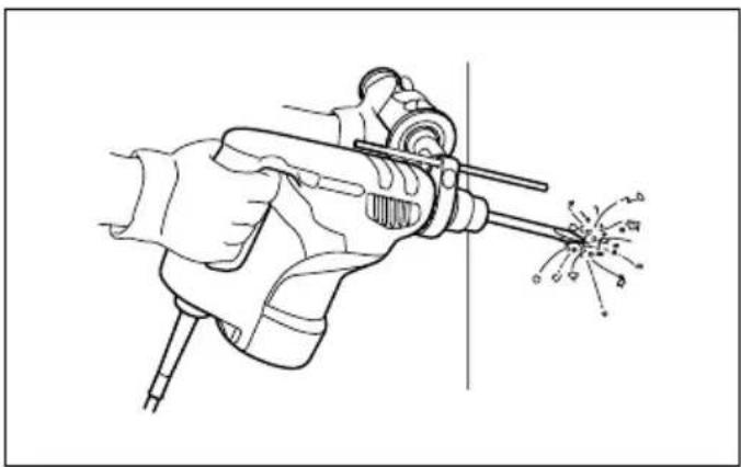
natural_image
Line drawing of a hand using a power tool to trigger sparks (no text or symbols)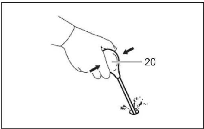
19 20
21 22
23 24
ENGLISH
Explanation of general view
| 1. Switch trigger | 9. Action mode changing knob | 17. Chuck cover |
| 2. Lamp | 10. Grip base | 18. Depth gauge |
| 3. Reversing switch lever | 11. Side grip | 19. Dust cup |
| 4. Quick change chuck for SDS-plus | 12. Teeth | 20. Blow-out bulb |
| 5. Change cover line | 13. Protrusion | 21. Chuck adapter |
| 6. Change cover | 14. Bit shank | 22. Keyless drill chuck |
| 7. Spindle | 15. Bit grease | 23. Sleeve |
| 8. Quick change drill chuck | 16. Bit | 24. Ring |
SPECIFICATIONS
| Model | HR2800/ HR2810 | HR2810T | HR2811F | HR2811FT | ||
| Capacities | Concrete | Tungsten-carbide tipped bit | 28 mm | |||
| Core bit 80 mm | ||||||
| Diamond core bit (dry type) | 80 mm | |||||
| Steel | 13 mm | |||||
| Wood | 32 mm | |||||
| No load speed ( min^-1 ) | 0 - 1,100 | |||||
| Blows per minute | 0 - 4,500 | |||||
| Overall length | 314 mm | 339 mm | 320 mm | 345 mm | ||
| Net weight | 3.2 kg | 3.3 kg | 3.2 kg | 3.4 kg | ||
| Safety class | 回/II | |||||
- Due to our continuing program of research and development, the specifications herein are subject to change without notice.
• Note: Specifications may differ from country to country.
Symbols
END201-3
The following show the symbols used for the equipment. Be sure that you understand their meaning before use.

..... Read instruction manual.

...... DOUBLE INSULATION
For Model HR2800 Intended use
ENE042-1
The tool is intended for hammer drilling and drilling in brick, concrete and stone.
It is also suitable for drilling without impact in wood, metal, ceramic and plastic.
For Model HR2810, HR2810T, HR2811F, HR2811FT Intended use ENE043-1
The tool is intended for hammer drilling and drilling in brick, concrete and stone as well as for chiselling work. It is also suitable for drilling without impact in wood, metal, ceramic and plastic.
Power supply
ENF002-1
The tool should be connected only to a power supply of the same voltage as indicated on the nameplate, and can only be operated on single-phase AC supply. They are double-insulated in accordance with European Standard and can, therefore, also be used from sockets without earth wire.
SPECIFIC SAFETY RULES GEB007-2
DO NOT let comfort or familiarity with product (gained from repeated use) replace strict adherence to rotary hammer safety rules. If you use this tool unsafely or incorrectly, you can suffer serious personal injury.
- Wear ear protectors. Exposure to noise can cause hearing loss.
- Use auxiliary handles supplied with the tool. Loss of control can cause personal injury.
- Hold power tools by insulated gripping surfaces when performing an operation where the cutting tool may contact hidden wiring or its own cord. Contact with a "live" wire will make exposed metal parts of the tool "live" and shock the operator.
- Wear a hard hat (safety helmet), safety glasses and/or face shield. Ordinary eye or sun glasses are NOT safety glasses. It is also highly recommended that you wear a dust mask and thickly padded gloves.
- Be sure the bit is secured in place before operation.
- Under normal operation, the tool is designed to produce vibration. The screws can come loose easily, causing a breakdown or accident. Check tightness of screws carefully before operation.
- In cold weather or when the tool has not been used for a long time, let the tool warm up for a while by operating it under no load. This will
loosen up the lubrication. Without proper warm-up, hammering operation is difficult.
-
Always be sure you have a firm footing. Be sure no one is below when using the tool in high locations.
-
Hold the tool firmly with both hands.
-
Keep hands away from moving parts.
-
Do not leave the tool running. Operate the tool only when hand-held.
-
Do not point the tool at any one in the area when operating. The bit could fly out and injure someone seriously.
-
Do not touch the bit or parts close to the bit immediately after operation; they may be extremely hot and could burn your skin.
-
Some material contains chemicals which may be toxic. Take caution to prevent dust inhalation and skin contact. Follow material supplier safety data.
SAVE THESE INSTRUCTIONS.
WARNING:
MISUSE or failure to follow the safety rules stated in this instruction manual may cause serious personal injury.
FUNCTIONAL DESCRIPTION
CAUTION:
- Always be sure that the tool is switched off and unplugged before adjusting or checking function on the tool.
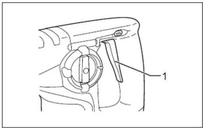
Switch action (Fig. 1)
CAUTION:
- Before plugging in the tool, always check to see that the switch trigger actuates properly and returns to the "OFF" position when released.
To start the tool, simply pull the switch trigger. Tool speed is increased by increasing pressure on the switch trigger. Release the switch trigger to stop.
Lighting up the lamps
For Models HR2811F, HR2811FT (Fig. 2)
CAUTION:
- Do not look in the light or see the source of light directly.
To turn on the lamp, pull the trigger. Release the trigger to turn it off.
NOTE:
- Use a dry cloth to wipe the dirt off the lens of lamp. Be careful not to scratch the lens of lamp, or it may lower the illumination.
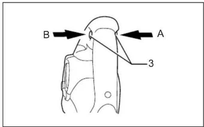
Reversing switch action (Fig. 3)
This tool has a reversing switch to change the direction of rotation. Depress the reversing switch lever from the A side for clockwise rotation or from the B side for counterclockwise rotation.
CAUTION:
• Always check the direction of rotation before operation.
- Use the reversing switch only after the tool comes to a complete stop. Changing the direction of rotation before the tool stops may damage the tool.
- When you operate the tool in counterclockwise rotation, the switch trigger is pulled only halfway and the tool runs at half speed.
Changing the quick change chuck for SDS-plus
For model HR2810T, HR2811FT
The quick change chuck for SDS-plus can be easily exchanged for the quick change drill chuck.
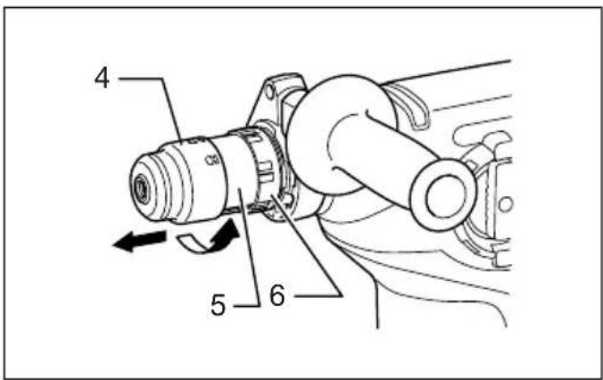
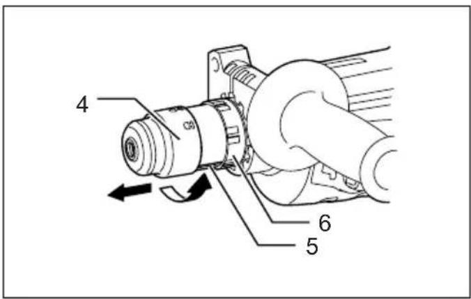
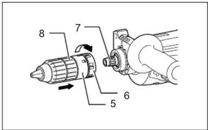
Removing the quick change chuck for SDS-plus (Fig. 4)
CAUTION:
- Before removing the quick change chuck for SDS-plus, always remove the bit.
Grasp the change cover of the quick change chuck for SDS-plus and turn in the direction of the arrow until the change cover line moves from the symbol to the symbol. Pull forcefully in the direction of the arrow.
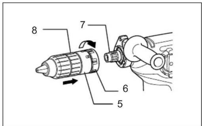
Attaching the quick change drill chuck (Fig. 5)
Check the line of the quick change drill chuck shows the symbol. Grasp the change cover of the quick change drill chuck and set the line to the symbol. Place the quick change drill chuck on the spindle of the tool. Grasp the change cover of the quick change drill chuck and turn the change cover line to the symbol until a click can clearly be heard.
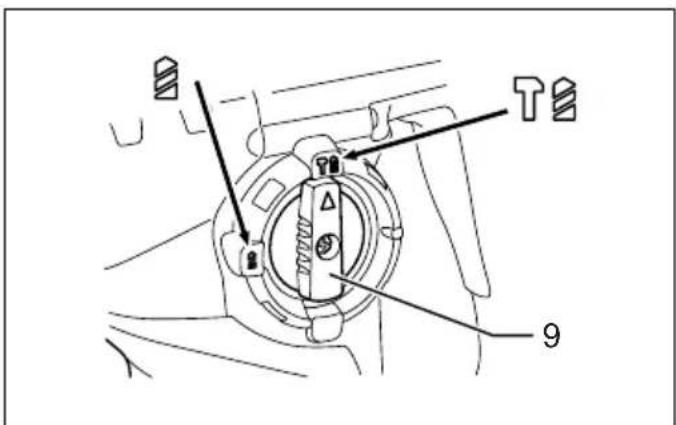
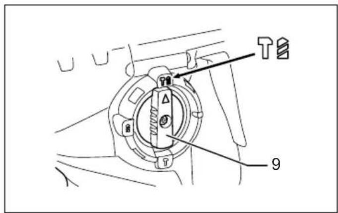
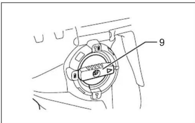
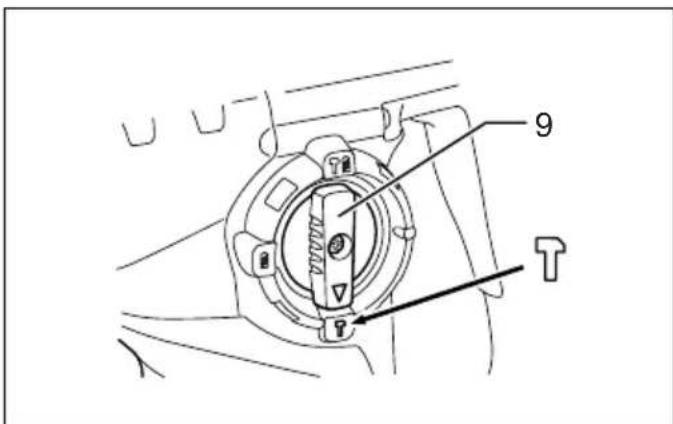
Selecting the action mode
For Model HR2800 (Fig. 6)
This tool employs an action mode changing knob. Select one of the two modes suitable for your work needs by using this knob.
For rotation only, turn the knob so that the arrow on the knob points toward the symbol on the tool body.
For rotation with hammering, turn the knob so that the arrow on the knob points toward the symbol on the tool body.
CAUTION:
- Always set the knob fully to your desired mode symbol. If you operate the tool with the knob positioned halfway between the mode symbols, the tool may be damaged.
- Use the knob after the tool comes to a complete stop.
For models HR2810, HR2810T, HR2811F, HR2811FT Rotation with hammering (Fig. 7)
For drilling in concrete, masonry, etc., rotate the action mode changing knob to the symbol. Use a tungsten-carbide tipped bit.
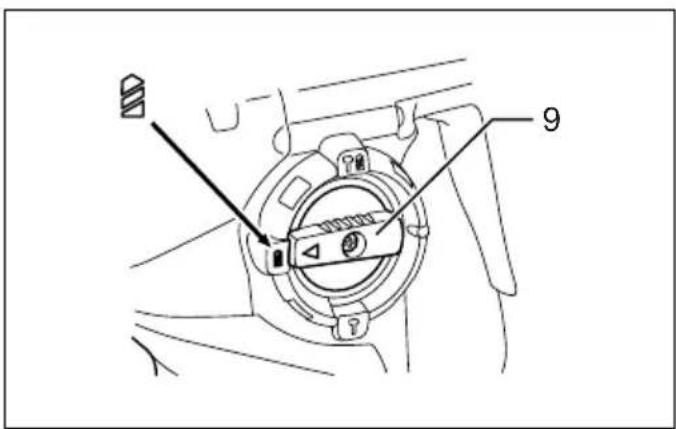
Rotation only (Fig. 8)
For drilling in wood, metal or plastic materials, lock button and rotate the action mode changing knob to the symbol. Use a twist drill bit or wood bit.
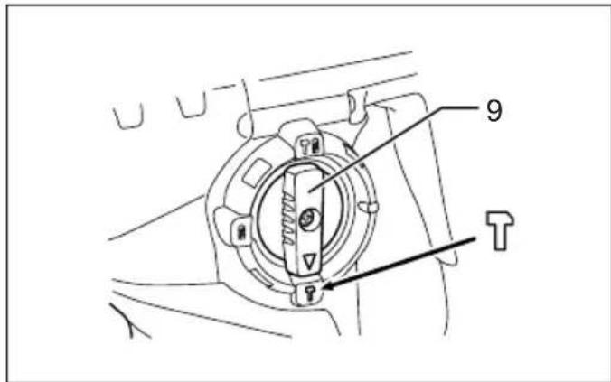
Hammering only (Fig. 9)
For chipping, scaling or demolition operations, rotate the action mode changing knob to the symbol. Use a bull point, cold chisel, scaling chisel, etc.
CAUTION:
- Do not rotate the action mode changing knob when the tool is running under load. The tool will be damaged.
- To avoid rapid wear on the mode change mechanism, be sure that the action mode changing knob is always positively located in one of the three action mode positions.
Torque limiter
The torque limiter will actuate when a certain torque level is reached. The motor will disengage from the output shaft. When this happens, the bit will stop turning.
CAUTION:
- As soon as the torque limiter actuates, switch off the tool immediately. This will help prevent premature wear of the tool.
- Bits such as hole saw, which tend to pintch or catch easily in the hole, are not appropriate for this tool. This is because they will cause the torque limiter to actuate too frequently.
ASSEMBLY
CAUTION:
• Always be sure that the tool is switched off and unplugged before carrying out any work on the tool.
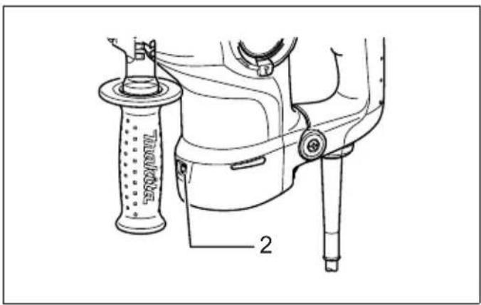
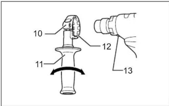
Side grip (auxiliary handle) (Fig. 10)
CAUTION:
- Always use the side grip to ensure operating safety. Install the side grip so that the teeth on the grip fit in between the protrusions on the tool barrel. Then tighten the grip by turning clockwise at the desired position. It may be swung 360^ so as to be secured at any position.
Bit grease
Coat the bit shank head beforehand with a small amount of bit grease (about 0.5 - 1 g).
This chuck lubrication assures smooth action and longer service life.
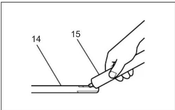
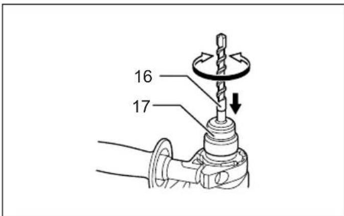
Installing or removing the bit (Fig. 11)
Clean the bit shank and apply bit grease before installing the bit. (Fig. 12)
Insert the bit into the tool. Turn the bit and push it in until it engages.
After installing, always make sure that the bit is securely held in place by trying to pull it out.
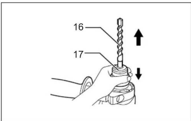
To remove the bit, pull the chuck cover down all the way and pull the bit out. (Fig. 13)
Bit angle (when chipping, scaling or demolishing)
For models HR2810, HR2810T, HR2811F, HR2811FT (Fig. 14)
The bit can be secured at the desired angle. To change the bit angle, rotate the action mode changing knob to the O symbol. Turn the bit to the desired angle.
Rotate the action mode changing knob to the symbol. Then make sure that the bit is securely held in place by turning it slightly. (Fig. 15)
Depth gauge (Fig. 16)
The depth gauge is convenient for drilling holes of uniform depth. Loosen the side grip and insert the depth gauge into the hole in the side grip. Adjust the depth gauge to the desired depth and tighten the side grip.
NOTE:
- The depth gauge cannot be used at the position where the depth gauge strikes against the gear housing.
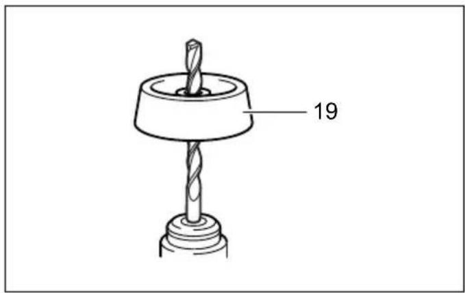
Dust cup (Fig. 17)
Use the dust cup to prevent dust from falling over the tool and on yourself when performing overhead drilling operations. Attach the dust cup to the bit as shown in the figure. The size of bits which the dust cup can be attached to is as follows.
| Bit diameter | |
| Dust cup 5 6 mm - | 14.5 mm |
| Dust cup 9 12 mm - | 16 mm |
OPERATION
CAUTION:
- Always use the side grip (auxiliary handle) and firmly hold the tool by both side grip and switch handle during operations.
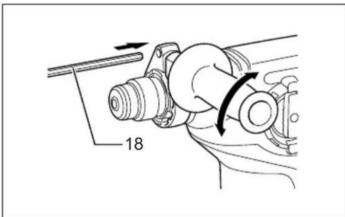
Hammer drilling operation (Fig. 18)
Set the action mode changing knob to the symbol.
Position the bit at the desired location for the hole, then pull the switch trigger.
Do not force the tool. Light pressure gives best results. Keep the tool in position and prevent it from slipping away from the hole.
Do not apply more pressure when the hole becomes clogged with chips or particles. Instead, run the tool at an idle, then remove the bit partially from the hole. By repeating this several times, the hole will be cleaned out and normal drilling may be resumed.
CAUTION:
- There is a tremendous and sudden twisting force exerted on the tool/bit at the time of hole break-through, when the hole becomes clogged with chips and particles, or when striking reinforcing rods embedded in the concrete. Always use the side grip (auxiliary handle) and firmly hold the tool by both side grip and switch handle during operations. Failure to do so may result in the loss of control of the tool and potentially severe injury.
NOTE:
Eccentricity in the bit rotation may occur while operating the tool with no load. The tool automatically centers itself during operation. This does not affect the drilling precision.
Blow-out bulb (optional accessory) (Fig. 19)
After drilling the hole, use the blow-out bulb to clean the dust out of the hole.
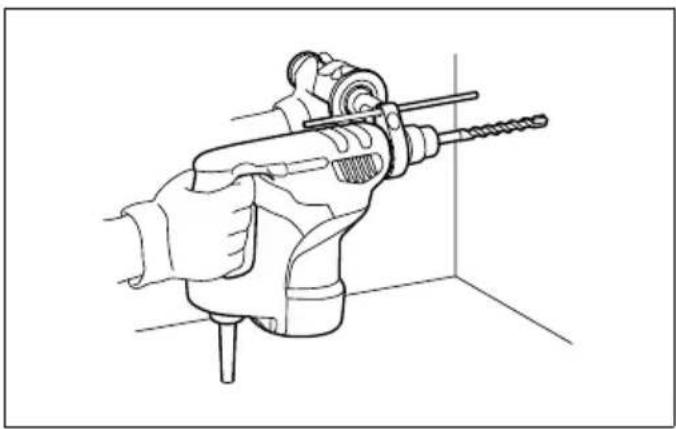
Chipping/Scaling/Demolition
For models HR2810, HR2810T, HR2811F, HR2811FT only (Fig. 20)
Set the action mode changing knob to the symbol. Hold the tool firmly with both hands. Turn the tool on and apply slight pressure on the tool so that the tool will not bounce around, uncontrolled. Pressing very hard on the tool will not increase the efficiency.
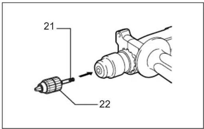
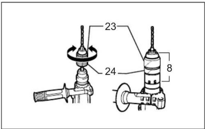
Drilling in wood or metal (Fig. 21 - 24)
For Model HR2800, HR28010, HR2810F
Use the optional drill chuck assembly. When installing it, refer to "Installing or removing the bit" described on the previous page. Set the action mode changing knob so that the pointer points to the symbol.
For model HR2810T, HR2811FT
Use the quick change drill chuck as standard equipment. When installing it, refer to "changing the quick change chuck for SDS-plus" described on the previous page. Hold the ring and turn the sleeve counterclockwise to open the chuck jaws. Place the bit in the chuck as far as it will go. Hold the ring firmly and turn the sleeve clockwise to tighten the chuck. To remove the bit, hold the ring and turn the sleeve counterclockwise. Set the action mode changing knob to the symbol. You can drill up to 13 mm diameter in metal and up to 32 mm diameter in wood.
CAUTION:
- Never use "rotation with hammering" when the quick change drill chuck is installed on the tool. The quick change drill chuck may be damaged. Also, the drill chuck will come off when reversing the tool.
- Pressing excessively on the tool will not speed up the drilling. In fact, this excessive pressure will only serve to damage the tip of your bit, decrease the tool performance and shorten the service life of the tool.
- There is a tremendous twisting force exerted on the tool/bit at the time of hole breakthrough. Hold the tool firmly and exert care when the bit begins to break through the workpiece.
- A stuck bit can be removed simply by setting the reversing switch to reverse rotation in order to back out. However, the tool may back out abruptly if you do not hold it firmly.
- Always secure small workpieces in a vise or similar hold-down device.
Diamond core drilling
When performing diamond core drilling operations, always set the change lever to the position to use "rotation only" action.
CAUTION:
- If performing diamond core drilling operations using "rotation with hammering" action, the diamond core bit may be damaged.
MAINTENANCE
CAUTION:
• Always be sure that the tool is switched off and unplugged before attempting to perform inspection or maintenance.
To maintain product SAFETY and RELIABILITY, repairs, carbon brush inspection and replacement, any other maintenance or adjustment should be performed by Makita Authorized Service Centers, always using Makita replacement parts.
ACCESSORIES
CAUTION:
• These accessories or attachments are recommended for use with your Makita tool specified in this manual. The use of any other accessories or attachments might present a risk of injury to persons. Only use accessory or attachment for its stated purpose.
If you need any assistance for more details regarding these accessories, ask your local Makita Service Center.
• SDS-Plus Carbide-tipped bits
- Bull point
- Core bit
- Cold chisel
- Diamond core bit
- Scaling chisel
- Grooving chisel
- Drill chuck assembly
- Drill chuck S13
- Chuck adapter
- Chuck key S13
- Bit grease
- Side grip
- Depth gauge
- Blow-out bulb
- Dust cup
- Dust extractor attachment
- Safety goggles
- Plastic carrying case
• Keyless drill chuck
FRANÇAIS
Descriptif
EC-DECLARATION OF CONFORMITY ENH101-7
Model; HR2800, HR2810, HR2810T, HR2811F, HR2811FT
We declare under our sole responsibility that this product is in compliance with the following standards of standardized documents;
EN60745, EN55014, EN61000 in accordance with Council Directives, 2004/108/EC, 98/37/EC.
FRANÇAIS
DÉCLARATION DE CONFORMITÉ CE ENH101-7
Modèle HR2800, HR2810, HR2810T, HR2811F, HR2811FT
Michigan Drive, Tongwell, Milton Keynes,
Bucks MK15 8JD, ENGLAND
PORTUGUÊS
Michigan Drive, Tongwell, Milton Keynes,
Bucks MK15 8JD, ENGLAND
ENGLISH
For Model HR2800
For European countries only ENG102-1
Noise
The typical A-weighted noise level determined according to 60745-2-6:
Sound pressure level ( L_pA ): 89 dB (A)
Sound power level (LWA): 100 dB (A)
Uncertainty (K): 3 dB (A)
Wear ear protection
FRANÇAIS
Michigan Drive, Tongwell, Milton Keynes,
Bucks MK15 8JD, ENGLAND
PORTUGUÊS
Para o modelo HR2800
Apenas para os países europeus ENG102-1
Ruído
Michigan Drive, Tongwell, Milton Keynes,
Bucks MK15 8JD, ENGLAND
ENGLISH
For Model HR2800
For European countries only
Vibration ENG217-1
The vibration total value (tri-axial vector sum) determined according to EN60745-2-6:
Work mode: hammer drilling into concrete, 10 mm diameter and 100 mm depth
Vibration emission (a _h,HD ): 20 m/s ^2
Uncertainty (K): 1.5 m/s ^2
FRANÇAIS
Michigan Drive, Tongwell, Milton Keynes,
Bucks MK15 8JD, ENGLAND
PORTUGUÊS
Para o modelo HR2800
Michigan Drive, Tongwell, Milton Keynes,
Bucks MK15 8JD, ENGLAND
ENGLISH
For Model HR2810, 2810T
For European countries only ENG102-1
Noise
The typical A-weighted noise level determined according to 60745-2-6:
Sound pressure level ( L_pA ): 89 dB (A)
Sound power level (LWA): 100 dB (A)
Uncertainty (K): 3 dB (A)
Wear ear protection
FRANÇAIS
Michigan Drive, Tongwell, Milton Keynes,
Bucks MK15 8JD, ENGLAND
PORTUGUÊS
Para os modelos HR2810 e 2810T
Apenas para os países europeus ENG102-1
Ruído
Michigan Drive, Tongwell, Milton Keynes,
Bucks MK15 8JD, ENGLAND
ENGLISH
For Model HR2810, 2810T
For European countries only
Vibration ENG215-1
The vibration total value (tri-axial vector sum) determined according to EN60745-2-6:
Work mode: chiseling function
Vibration emission (a _h,CHeq ): 15.5 m/s ^2
Uncertainty (K): 1.5 m/s ^2
ENG303-1
Work mode: hammer drilling into concrete, 10 mm diameter and 100 mm depth
Vibration emission (a _h,HD ): 20 m/s ^2
Uncertainty (K): 1.5 m/s ^2
FRANÇAIS
Michigan Drive, Tongwell, Milton Keynes,
Bucks MK15 8JD, ENGLAND
PORTUGUÊS
Para os modelos HR2810 e 2810T
Michigan Drive, Tongwell, Milton Keynes,
Bucks MK15 8JD, ENGLAND
ENGLISH
For Model HR2811F, HR2811FT
For European countries only ENG102-1
Noise
The typical A-weighted noise level determined according to 60745-2-6:
Sound pressure level ( L_pA ): 90 dB (A)
Sound power level (LWA): 101 dB (A)
Uncertainty (K): 3 dB (A)
Wear ear protection
FRANÇAIS
Michigan Drive, Tongwell, Milton Keynes,
Bucks MK15 8JD, ENGLAND
PORTUGUÊS
Para os modelos HR2811F e HR2811FT
Apenas para os países europeus ENG102-1
Ruído
Michigan Drive, Tongwell, Milton Keynes,
Bucks MK15 8JD, ENGLAND
ENGLISH
For Model HR2811F, HR2811FT
For European countries only
Vibration ENG215-1
The vibration total value (tri-axial vector sum) determined according to EN60745-2-6:
Work mode: chiseling function
Vibration emission (a _h,CHeq ): 11.5 m/s ^2
Uncertainty (K): 1.5 m/s ^2
ENG303-1
Work mode: hammer drilling into concrete, 10 mm diameter and 100 mm depth
Vibration emission (a _h,HD ): 15 m/s ^2
Uncertainty (K): 1.5 m/s ^2
FRANÇAIS
Michigan Drive, Tongwell, Milton Keynes,
Bucks MK15 8JD, ENGLAND
PORTUGUÊS
Para os modelos HR2811F e HR2811FT
Vibrationsemission (a _h,HP ): 15 m/s ^2
Michigan Drive, Tongwell, Milton Keynes,
Bucks MK15 8JD, ENGLAND
Makita Corporation
Anjo, Aichi, Japan
884729-991