S-MAK32FCT - Hammer MAKITA - Free user manual and instructions
Find the device manual for free S-MAK32FCT MAKITA in PDF.

User questions about S-MAK32FCT MAKITA
0 question about this device. Answer the ones you know or ask your own.
Ask a new question about this device
Download the instructions for your Hammer in PDF format for free! Find your manual S-MAK32FCT - MAKITA and take your electronic device back in hand. On this page are published all the documents necessary for the use of your device. S-MAK32FCT by MAKITA.
USER MANUAL S-MAK32FCT MAKITA
natural_image
Line drawing of a compact drill press with labeled components (no text or symbols beyond branding)008536

DOUBLE INSULATION
ENGLISH (Original instructions)
SPECIFICATIONS
| Model | HR3200C | HR3210C | |||
| Capacities | Concrete | Tungsten-carbide tipped bit 32 mm | |||
| Core bit 90 mm | |||||
| Steel | 13 | ||||
| Wood | 32 | ||||
| No load speed (min-1) | 315 | ||||
| Blows per minute 1,650 - 3,300 | |||||
| Overall length 398 mm 424 mm | |||||
| Net weight 4.8 kg 5.2 kg 5.4 kg | |||||
| Safety class /II | ☐ | ||||
- Due to our continuing programme of research and development, the specifications herein are subject to change without notice.
- Specifications may differ from country to country.
• Weight according to EPTA-Procedure 01/2003
END201-5
Symbols
The following show the symbols used for the equipment. Be sure that you understand their meaning before use.


- Read instruction manual.

- DOUBLE INSULATION

• Only for EU countries
Do not dispose of electric equipment together with household waste material! In observance of European Directive 2002/96/EC on waste electric and electronic equipment and its implementation in accordance with national law, electric equipment that have reached the end of their life must be collected separately and returned to an environmentally compatible recycling facility.
ENE044-1
Intended use
The tool is intended for hammer drilling in brick, concrete and stone as well as for chiselling work.
ENF002-1
Power supply
The tool should be connected only to a power supply of the same voltage as indicated on the nameplate, and can only be operated on single-phase AC supply. They are double-insulated in accordance with European Standard and can, therefore, also be used from sockets without earth wire.
ENG905-1
Noise
The typical A-weighted noise level determined according to EN60745:
Model HR3200C,HR3210C
Sound pressure level ( L_pA ): 89 dB(A)
Sound power level ( L_WA ): 100 dB(A)
Uncertainty (K): 3 dB(A)
Model HR3210FCT
Sound pressure level ( L_pA ): 88 dB(A)
Sound power level ( L_WA ): 99 dB(A)
Uncertainty (K) : 3 dB(A)
Wear ear protection
ENG900-1
Vibration
The vibration total value (tri-axial vector sum) determined according to EN60745:
Model HR3200C
Work mode : hammer drilling into concrete
Vibration emission ( a_h,HD ): 18.0 m/s ^2
Uncertainty (K) : 1.5 m/s²
Work mode : chiseling
Vibration emission ( a_h,CHeq ): 12.5 m/s ^2
Uncertainty (K) : 1.5 m/s ^4
Work mode: drilling into metal
Vibration emission ( a_h,D ): 2.5 m/s ^2 or less
Uncertainty (K) : 1.5 m/s²
Model HR3210C
Work mode : hammer drilling into concrete
Vibration emission ( a_h,HD ): 10.0 m/s ^2
Uncertainty (K) : 1.5 m/s²
Work mode : chiseling
Vibration emission ( a_h,CHeq ): 7.5 m/s ^2
Uncertainty (K) : 1.5 m/s ^2
Work mode: drilling into metal
Vibration emission (a _h,D ): 2.5 m/s ^2 or less
Uncertainty (K) : 1.5 m/s ^2
Model HR3210FCT
Work mode : hammer drilling into concrete
Vibration emission ( a_h,HD ): 10.0 m/s ^2
Uncertainty (K) : 1.5 m/s ^2
Work mode : chiseling
Vibration emission (a _h,CHeq ) : 8.0 m/s ^2
Uncertainty (K) : 1.5 m/s ^2
Work mode: drilling into metal
Vibration emission (a _h,D ) : 2.5 m/s ^2 or less
Uncertainty (K) : 1.5 m/s ^2
ENG901-1
- The declared vibration emission value has been measured in accordance with the standard test method and may be used for comparing one tool with another.
- The declared vibration emission value may also be used in a preliminary assessment of exposure.
WARNING:
- The vibration emission during actual use of the power tool can differ from the declared emission value depending on the ways in which the tool is used.
- Be sure to identify safety measures to protect the operator that are based on an estimation of exposure in the actual conditions of use (taking account of all parts of the operating cycle such as the times when the tool is switched off and when it is running idle in addition to the trigger time).
ENH101-14
For European countries only
EC Declaration of Conformity
We Makita Corporation as the responsible manufacturer declare that the following Makita machine(s):
Designation of Machine:
Rotary Hammer
Model No./ Type: HR3200C, HR3210C, HR3210FCT
are of series production and
Conforms to the following European Directives: 2006/42/EC
And are manufactured in accordance with the following standards or standardised documents:
EN60745
The technical documentation is kept by our authorised representative in Europe who is:
Makita International Europe Ltd.
Michigan Drive, Tongwell,
Milton Keynes, MK15 8JD, England
30.1.2009
000230
Tomoyasu Kato
Director
Makita Corporation
3-11-8, Sumiyoshi-cho,
Anjo, Aichi, JAPAN
GEA005-3
General Power Tool Safety Warnings
⚠ WARNING Read all safety warnings and all instructions. Failure to follow the warnings and instructions may result in electric shock, fire and/or serious injury.
Save all warnings and instructions for future reference.
The term "power tool" in the warnings refers to your mains-operated (corded) power tool or battery-operated (cordless) power tool.
Work area safety
- Keep work area clean and well lit. Cluttered or dark areas invite accidents.
- Do not operate power tools in explosive atmospheres, such as in the presence of flammable liquids, gases or dust. Power tools create sparks which may ignite the dust or fumes.
- Keep children and bystanders away while operating a power tool. Distractions can cause you to lose control.
Electrical safety
- Power tool plugs must match the outlet. Never modify the plug in any way. Do not use any adapter plugs with earthed (grounded) power tools. Unmodified plugs and matching outlets will reduce risk of electric shock.
- Avoid body contact with earthed or grounded surfaces such as pipes, radiators, ranges and refrigerators. There is an increased risk of electric shock if your body is earthed or grounded.
-
Do not expose power tools to rain or wet conditions. Water entering a power tool will increase the risk of electric shock.
-
Do not abuse the cord. Never use the cord for carrying, pulling or unplugging the power tool. Keep cord away from heat, oil, sharp edges or moving parts. Damaged or entangled cords increase the risk of electric shock.
- When operating a power tool outdoors, use an extension cord suitable for outdoor use. Use of a cord suitable for outdoor use reduces the risk of electric shock.
- If operating a power tool in a damp location is unavoidable, use a residual current device (RCD) protected supply. Use of an RCD reduces the risk of electric shock.
- Use of power supply via a RCD with a rated residual current of 30mA or less is always recommended.
Personal safety
- Stay alert, watch what you are doing and use common sense when operating a power tool. Do not use a power tool while you are tired or under the influence of drugs, alcohol or medication. A moment of inattention while operating power tools may result in serious personal injury.
- Use personal protective equipment. Always wear eye protection. Protective equipment such as dust mask, non-skid safety shoes, hard hat, or hearing protection used for appropriate conditions will reduce personal injuries.
- Prevent unintentional starting. Ensure the switch is in the off-position before connecting to power source and/or battery pack, picking up or carrying the tool. Carrying power tools with your finger on the switch or energising power tools that have the switch on invites accidents.
- Remove any adjusting key or wrench before turning the power tool on. A wrench or a key left attached to a rotating part of the power tool may result in personal injury.
- Do not overreach. Keep proper footing and balance at all times. This enables better control of the power tool in unexpected situations.
- Dress properly. Do not wear loose clothing or jewellery. Keep your hair, clothing, and gloves away from moving parts. Loose clothes, jewellery or long hair can be caught in moving parts.
- If devices are provided for the connection of dust extraction and collection facilities, ensure these are connected and properly used. Use of dust collection can reduce dust-related hazards.
Power tool use and care
- Do not force the power tool. Use the correct power tool for your application. The correct
power tool will do the job better and safer at the rate for which it was designed.
- Do not use the power tool if the switch does not turn it on and off. Any power tool that cannot be controlled with the switch is dangerous and must be repaired.
- Disconnect the plug from the power source and/or the battery pack from the power tool before making any adjustments, changing accessories, or storing power tools. Such preventive safety measures reduce the risk of starting the power tool accidentally.
- Store idle power tools out of the reach of children and do not allow persons unfamiliar with the power tool or these instructions to operate the power tool. Power tools are dangerous in the hands of untrained users.
- Maintain power tools. Check for misalignment or binding of moving parts, breakage of parts and any other condition that may affect the power tool's operation. If damaged, have the power tool repaired before use. Many accidents are caused by poorly maintained power tools.
- Keep cutting tools sharp and clean. Properly maintained cutting tools with sharp cutting edges are less likely to bind and are easier to control.
- Use the power tool, accessories and tool bits etc. in accordance with these instructions, taking into account the working conditions and the work to be performed. Use of the power tool for operations different from those intended could result in a hazardous situation.
Service
- Have your power tool serviced by a qualified repair person using only identical replacement parts. This will ensure that the safety of the power tool is maintained.
- Follow instruction for lubricating and changing accessories.
- Keep handles dry, clean and free from oil and grease.
GEB007-7
ROTARY HAMMER SAFETY WARNINGS
- Wear ear protectors. Exposure to noise can cause hearing loss.
- Use auxiliary handle(s), if supplied with the tool. Loss of control can cause personal injury.
- Hold power tool by insulated gripping surfaces, when performing an operation where the cutting accessory may contact hidden wiring or its own cord. Cutting accessory contacting a "live" wire may make exposed metal parts of the power tool "live" and could give the
operator an electric shock.
- Wear a hard hat (safety helmet), safety glasses and/or face shield. Ordinary eye or sun glasses are NOT safety glasses. It is also highly recommended that you wear a dust mask and thickly padded gloves.
- Be sure the bit is secured in place before operation.
- Under normal operation, the tool is designed to produce vibration. The screws can come loose easily, causing a breakdown or accident. Check tightness of screws carefully before operation.
- In cold weather or when the tool has not been used for a long time, let the tool warm up for a while by operating it under no load. This will loosen up the lubrication. Without proper warm-up, hammering operation is difficult.
- Always be sure you have a firm footing. Be sure no one is below when using the tool in high locations.
- Hold the tool firmly with both hands.
- Keep hands away from moving parts.
- Do not leave the tool running. Operate the tool only when hand-held.
- Do not point the tool at any one in the area when operating. The bit could fly out and injure someone seriously.
- Do not touch the bit or parts close to the bit immediately after operation; they may be extremely hot and could burn your skin.
- Some material contains chemicals which may be toxic. Take caution to prevent dust inhalation and skin contact. Follow material supplier safety data.
SAVE THESE INSTRUCTIONS.
⚠ WARNING:
DO NOT let comfort or familiarity with product (gained from repeated use) replace strict adherence to safety rules for the subject product. MISUSE or failure to follow the safety rules stated in this instruction manual may cause serious personal injury.
FUNCTIONAL DESCRIPTION
CAUTION:
• Always be sure that the tool is switched off and unplugged before adjusting or checking function on the tool.
Switch action
- Switch trigger
008537
CAUTION:
- Before plugging in the tool, always check to see that the switch trigger actuates properly and returns to the "OFF" position when released.
To start the tool, simply pull the switch trigger. Release the switch trigger to stop.
Lighting up the lamps
For Model HR3210FCT
- Lamp
008549
CAUTION:
- Do not look in the light or see the source of light directly.
To turn on the lamp, pull the trigger. Release the trigger to turn it off.
NOTE:
- Use a dry cloth to wipe the dirt off the lens of lamp. Be careful not to scratch the lens of lamp, or it may lower the illumination.
Speed change
- Adjusting dial
008538
The revolutions and blows per minute can be adjusted just by turning the adjusting dial. The dial is marked 1 (lowest speed) to 5 (full speed).
Refer to the table below for the relationship between the number settings on the adjusting dial and the revolutions/blows per minute.
| Number on adjusting dial | Revolutions per minute | Blows per minute |
| 5 | 630 | 3,300 |
| 4 | 590 | 3,100 |
| 3 | 480 | 2,500 |
| 2 | 370 | 1,900 |
| 1 | 315 | 1,650 |
008550
CAUTION:
- If the tool is operated continuously at low speeds for a long time, the motor will get overloaded, resulting in tool malfunction.
- The speed adjusting dial can be turned only as far as 5 and back to 1. Do not force it past 5 or 1, or the speed adjusting function may no longer work.
Changing the quick change chuck for SDS-plus
For Model HR3210FCT
The quick change chuck for SDS-plus can be easily exchanged for the quick change drill chuck.
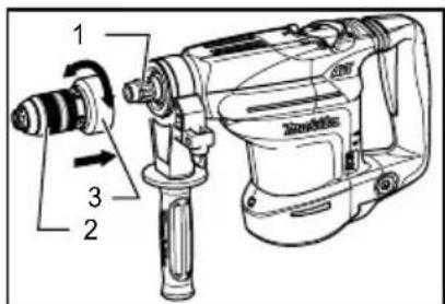
Removing the quick change chuck for SDS-plus
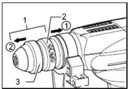
- Quick change chuck for SDS-plus
- Change cover
- Chuck cover
008608
CAUTION:
- Before removing the quick change chuck for SDS-plus always remove the bit.
Hold the change cover with the thumb and the middle finger and pull it in the direction arrow 1. With the change
cover pulled in that direction, hold the chuck cover with the index finger. While holding the chuck cover so, pull out the quick change chuck for SDS-plus in the direction of arrow 2 at a stroke.
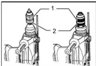
Attaching the quick change drill chuck
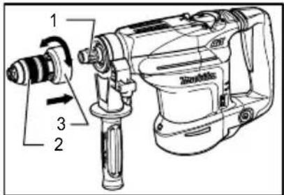
- Spindle
- Quick change drill chuck
- Change cover
008552
Grasp the change cover and place the quick change drill chuck on the spindle of the tool.
Make sure that the quick change drill chuck is secured by trying to pull it several times.
Selecting the action mode
Rotation with hammering
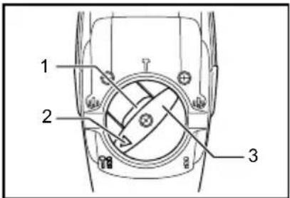
- Lock button
- Pointer
- Change lever
008540
For drilling in concrete, masonry, etc., depress the lock button and rotate the change lever so that the pointer points to the symbol. Use a tungsten-carbide tipped bit.
Rotation only
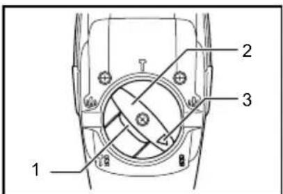
- Lock button
- Change lever
- Pointer
008600
For drilling in wood, metal or plastic materials, depress the lock button and rotate the change lever so that the pointer points to the Ⓠ symbol. Use a twist drill bit or wood bit.
Hammering only
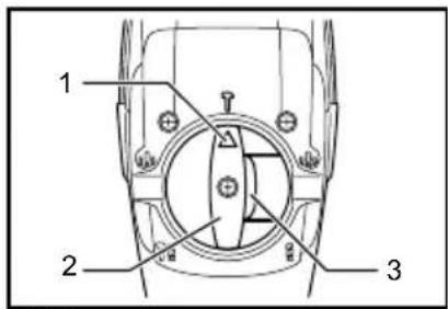
- Pointer
- Change lever
- Lock button
008539
For chipping, scaling or demolition operations, depress the lock button and rotate the change lever so that the pointer points to the ⚡ symbol. Use a bull point, cold chisel, scaling chisel, etc.
CAUTION:
- Do not rotate the change lever when the tool is running under load. The tool will be damaged.
- To avoid rapid wear on the mode change mechanism, be sure that the change lever is always positively located in one of the three action mode positions.
Torque limiter
The torque limiter will actuate when a certain torque level is reached. The motor will disengage from the output shaft. When this happens, the bit will stop turning.
CAUTION:
- As soon as the torque limiter actuates, switch off the tool immediately. This will help prevent premature wear of the tool.
Indicator lamp
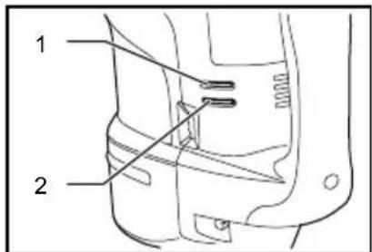
- Power-ON indicator lamp (green)
- Service indicator lamp (red)
008541
The green power-ON indicator lamp lights up when the tool is plugged. If the indicator lamp does not light up, the mains cord or the controller may be defective. The indicator lamp is lit but the tool does not start even if the tool is switched on, the carbon brushes may be worn out, or the controller, the motor or the ON/OFF switch may be defective.
The red service indicator lamp lights up when the carbon brushes are nearly worn out to indicate that the tool needs servicing. After approx. 8 hours of use, the motor will automatically be shut off.
ASSEMBLY
CAUTION:
• Always be sure that the tool is switched off and unplugged before carrying out any work on the tool.
Side grip
- Side grip
008542
CAUTION:
- Always use the side grip to ensure operating safety when drilling in concrete, masonry, etc.
The side grip swings around to either side, allowing easy handling of the tool in any position. Loosen the side grip by turning it counterclockwise, swing it to the desired position and then tighten it by turning clockwise.
Installing or removing the bit
- Bit shank
- Bit grease
003150
Clean the bit shank and apply bit grease before installing the bit.
Insert the bit into the tool. Turn the bit and push it in until it engages.
- Bit
- Chuck cover
008543
If the bit cannot be pushed in, remove the bit. Pull the chuck cover down a couple of times. Then insert the bit again. Turn the bit and push it in until it engages.
After installing, always make sure that the bit is securely held in place by trying to pull it out.
To remove the bit, pull the chuck cover down all the way and pull the bit out.
-
Bit
-
Chuck cover
008544
Bit angle (when chipping, scaling or demolishing)
-
Change lever
-
Lock button
-
Pointer
008545
The bit can be secured at 24 different angles. To change the bit angle, depress the lock button and rotate the change lever so that the pointer points to the symbol. Turn the bit to the desired angle.
Depress the lock button and rotate the change lever so that the pointer points to the ⚡ symbol. Then make sure that the bit is securely held in place by turning it slightly.
Depth gauge
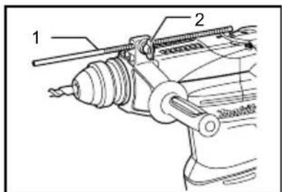
-
Depth gauge
-
Clamp screw
008546
The depth gauge is convenient for drilling holes of uniform depth. Loosen the clamp screw and adjust the depth gauge to the desired depth. After adjusting, tighten the clamp screw firmly.
NOTE:
- The depth gauge cannot be used at the position where the depth gauge strikes against the gear housing/motor housing.
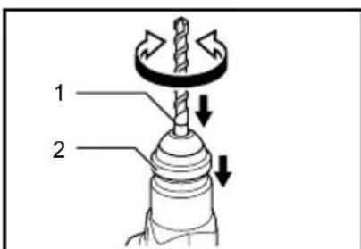
Dust cup
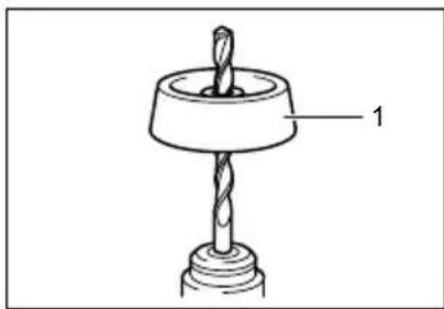
natural_image
Technical line drawing of a mechanical component with a drill bit and base (no text or symbols)- Dust cup
001300
Use the dust cup to prevent dust from falling over the tool and on yourself when performing overhead drilling operations. Attach the dust cup to the bit as shown in the figure. The size of bits which the dust cup can be attached to is as follows.
| Bit diameter | |
| Dust cup 5 6 mm - 14.5 | mm |
| Dust cup 9 | 12 mm - 16 mm |
006406
OPERATION
CAUTION:
• Always use the side grip (auxiliary handle) and firmly hold the tool by both side grip and switch handle during operations.
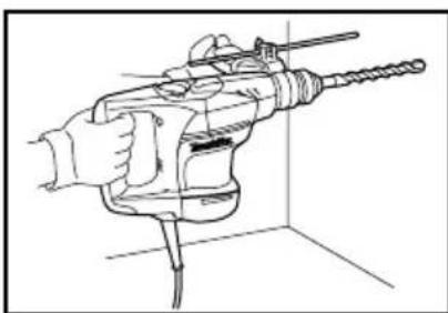
Hammer drilling operation
natural_image
Line drawing of a hand holding a drill bit in a 3D coordinate system (no text or symbols)008547
Set the change lever to the symbol.
Position the bit at the desired location for the hole, then pull the switch trigger. Do not force the tool. Light pressure gives best results. Keep the tool in position and prevent it from slipping away from the hole.
Do not apply more pressure when the hole becomes clogged with chips or particles. Instead, run the tool at an idle, then remove the bit partially from the hole. By repeating this several times, the hole will be cleaned out and normal drilling may be resumed.
CAUTION:
- When the bit begins to break through concrete or if the bit strikes reinforcing rods embedded in concrete, the tool may react dangerously. Maintain good balance and safe footing while holding the
tool firmly with both hands to prevent dangerous reaction.
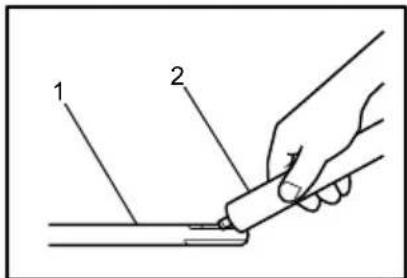
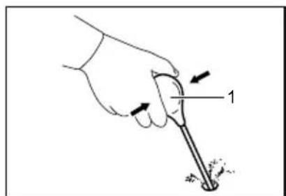
Blow-out bulb (optional accessory)
natural_image
Illustration of a hand holding a tool with arrows indicating motion or force direction (no text or symbols)- Blow-out bulb
002449
After drilling the hole, use the blow-out bulb to clean the dust out of the hole.
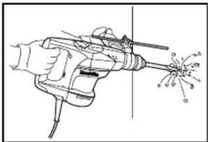
Chipping/Scaling/Demolition
natural_image
Line drawing of a hand using a power drill to trigger an electric shock (no text or symbols)008548
Set the change lever to the symbol.
Hold the tool firmly with both hands. Turn the tool on and apply slight pressure on the tool so that the tool will not bounce around, uncontrolled. Pressing very hard on the tool will not increase the efficiency.
Drilling in wood or metal
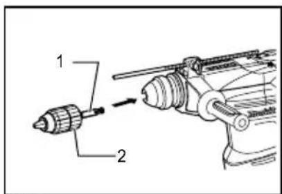
- Chuck adapter
- Keyless drill chuck
008551
- Spindle
- Quick change drill chuck
- Change cover
- Sleeve
- Ring
008553
For Model HR3200C,HR3210C
Use the optional drill chuck assembly. When installing it, refer to "Installing or removing the bit" described on the previous page.
Set the change lever so that the pointer points to the Ⓠ symbol.
For Model HR3210FCT
Use the quick change drill chuck as standard equipment. When installing it, refer to "changing the quick change chuck for SDS-plus" described on the previous page.
Hold the ring and turn the sleeve counterclockwise to open the chuck jaws. Place the bit in the chuck as far as it will go. Hold the ring firmly and turn the sleeve clockwise to tighten the chuck. To remove the bit, hold the ring and turn the sleeve counterclockwise.
Set the change lever to the symbol.
You can drill up to 13 mm diameter in metal and up to 32 mm diameter in wood.
CAUTION:
- Never use "rotation with hammering" when the quick change drill chuck is installed on the tool. The quick change drill chuck may be damaged.
- Pressing excessively on the tool will not speed up the drilling. In fact, this excessive pressure will only serve to damage the tip of your bit, decrease the tool performance and shorten the service life of the tool.
- There is a tremendous twisting force exerted on the tool/bit at the time of hole breakthrough. Hold the tool firmly and exert care when the bit begins to break through the workpiece.
• Always secure small workpieces in a vise or similar hold-down device.
Diamond core drilling
When performing diamond core drilling operations, always set the change lever to the 8 position to use "rotation only" action.
CAUTION:
- If performing diamond core drilling operations using "rotation with hammering" action, the diamond core bit may be damaged.
008552
MAINTENANCE
CAUTION:
• Always be sure that the tool is switched off and unplugged before attempting to perform inspection or maintenance.
- Never use gasoline, benzine, thinner, alcohol or the like. Discoloration, deformation or cracks may result.
Lubrication
CAUTION:
• This servicing should be performed by Makita Authorized or Factory Service Centers only.
This tool requires no hourly or daily lubrication because it has a grease-packed lubrication system. Lubricate the tool every time the carbon brushes are replaced.
Run the tool for several minutes to warm it up. Switch off and unplug the tool.
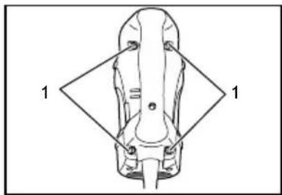
natural_image
Top-down diagram of a mechanical component with labeled parts (no text or symbols present)- Screws
008601
Loosen the four screws and remove the handle. Note that the top screws are different from other screws.
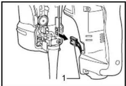
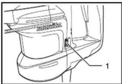
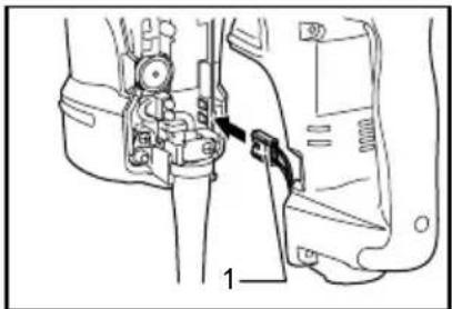
- Connector
008607
Disconnect the connector by pulling them.
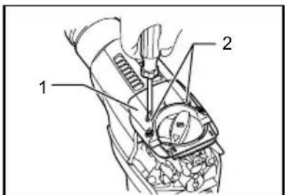
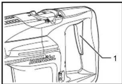
- Crank cap cover
- Screws
008602
Loosen the two screws on crank cap cover and remove the crank cap cover.
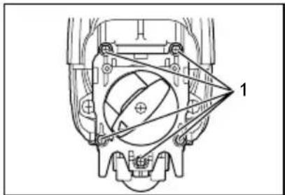
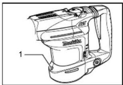
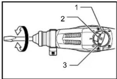
natural_image
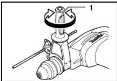
Technical diagram of a mechanical assembly with labeled component 1 (no text or symbols present)- Screws
008603
Align the change lever with the symbol loosen the five screws and then remove the crank cap.
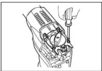
natural_image
Line drawing of a mechanical device with hands operating it (no text or symbols)008604
CAUTION:
- Always remove the crank cap only after aligning the change lever with the symbol . Never remove it forcibly without aligning the change lever with the symbol . Failure to do so does not allow reassembling.
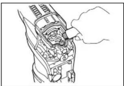
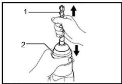
natural_image
Line drawing of a mechanical device with internal components and a hand inserting a component (no text or symbols)008605
Rest the tool on the table with the bit end pointing upwards. This will allow the old grease to collect inside the crank housing.
Wipe out the old grease inside and replace with a fresh grease (30 g). Use only Makita genuine hammer grease (optional accessory). Filling with more than the specified amount of grease (approx. 30 g) can cause faulty hammering action or tool failure. Fill only with the specified amount of grease.
CAUTION:
- Be careful not to damage the connector or lead wires especially when wiping out the old grease. To reassemble the tool, follow the disassembling procedure in reverse.
CAUTION:
- Do not tighten the crank cap excessively. It is made of resin and is subject to breakage.
natural_image
Technical line drawing of a mechanical assembly with no visible text or symbols- Connector
008606
Connect the connector firmly and then reinstall the handle.
CAUTION:
- Be careful not to damage the connector or lead wires especially when installing the handle.
To maintain product SAFETY and RELIABILITY, repairs, carbon brush inspection and replacement, any other maintenance or adjustment should be performed by Makita Authorized Service Centers, always using Makita replacement parts.
ACCESSORIES
CAUTION:
• These accessories or attachments are recommended for use with your Makita tool specified in this manual. The use of any other accessories or attachments might present a risk of injury to persons. Only use accessory or attachment for its stated purpose.
If you need any assistance for more details regarding these accessories, ask your local Makita Service Center.
- SDS-Plus Carbide-tipped bits
- Bull point
- Core bit
- Cold chisel
- Diamond core bit
- Hammer grease
- Scaling chisel
- Grooving chisel
- Drill chuck assembly
- Drill chuck S13
- Chuck adapter
- Chuck key S13
- Bit grease
- Side grip
- Depth gauge
- Blow-out bulb
- Dust cup
- Safety goggles
- Plastic carrying case
Makita Corporation
Anjo, Aichi, Japan