UFP 5 h - Boiler STIEBEL ELTRON - Free user manual and instructions
Find the device manual for free UFP 5 h STIEBEL ELTRON in PDF.
User questions about UFP 5 h STIEBEL ELTRON
0 question about this device. Answer the ones you know or ask your own.
Ask a new question about this device
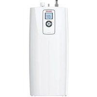
Download the instructions for your Boiler in PDF format for free! Find your manual UFP 5 h - STIEBEL ELTRON and take your electronic device back in hand. On this page are published all the documents necessary for the use of your device. UFP 5 h by STIEBEL ELTRON.
USER MANUAL UFP 5 h STIEBEL ELTRON

www.stiebel-eltron.com/registration
INSTALLATION
7. Sicherheit
- General information 13
1.1 Safety instructions 13
1.2 Other symbols in this documentation 13
1.3 Units of measurement 13 - Safety 13
2.1 Intended use 13
2.2 General safety instructions 13
2.3 Test symbols 14 - Appliance description 14
3.1 Operation 14 - Cleaning, care and maintenance 14
- Troubleshooting 14
INSTALLATION
- Safety 15
6.1 General safety instructions 15
6.2 Instructions, standards and regulations 15 - Appliance description 15
7.1 Standard delivery 15
7.2 Required accessories 15
8.Preparations 15
8.1 Installation site 15 - Installation 15
9.1 Appliance installation 15
9.2 Water connection 16
9.3 Power supply 16 - Commissioning 16
10.1 Initial start-up 16
10.2 Recommissioning 17 - Settings 17
11.1 Setting the temperature limit 17 - Shutdown 17
- Troubleshooting 17
- Maintenance 17
14.1 Draining the appliance 17
14.2 Opening the appliance 18
14.3 Descaling the appliance 18
14.4 Checking the earth conductor 18
14.5 Replacing the power cable 18
14.6 Positioning the temperature sensor in its protective pipe 18 - Specification 18
15.1 Dimensions and connections 18
15.2 Wiring diagram 18
15.3 Heat-up diagram 19
15.4 Country-specific approvals and certifications 19
15.5 Extreme operating and fault conditions 19
15.6 Details on energy consumption 19
15.7 Data table 19
GUARANTEE
ENVIRONMENT AND RECYCLING
SPECIAL INFORMATION
- The appliance may be used by children aged 8 and older and persons with reduced physical, sensory or mental capabilities or a lack of experience and know-how, provided that they are supervised or they have been instructed on how to use the appliance safely and have understood the resulting risks. Children must never play with the appliance. Children must never clean the appliance or perform user maintenance unless they are supervised.
- When permanently connected to the power supply using a dedicated junction box, the appliance must be able to be isolated from the mains power supply by an isolator that disconnects all poles with at least 3mm contact separation.
- The power cable may only be replaced (for example if damaged) by a qualified contractor authorised by the manufacturer, using an original spare part.
- Never connect the appliance via a time switch.
- Secure the appliance as described in chapter "Installation / Installation".
- During heating, expansion water drips from the tap outlet.
- The appliance must only be installed with an open (non-pressurised) tap.
- Never subject the appliance to water pressure.
- The tap outlet has a vent function. Scale build-up can block the outlet and subject the appliance to pressure.
- Never seal the tap outlet.
- Only use special aerators for non-pressurised water heaters.
- Never extend the tap outlet with a hose.
- Drain the appliance as described in chapter "Installation / Maintenance / Draining the appliance".
OPERATION
General information
OPERATION
1. General information
The chapters "Special Information" and "Operation" are intended for both the user and qualified contractors.
The chapter "Installation" is intended for qualified contractors.

Note
Read these instructions carefully before using the appliance and retain them for future reference.
Pass on the instructions to a new user if required.
1.1 Safety instructions
1.1.1 Layout of safety instructions

KEYWORD Type of risk
Here, possible consequences are listed that may result from failure to observe the safety instructions.
Steps to prevent the risk are listed.
1.1.2 Symbols, type of risk
Symbol Type of risk

Injury

Electrocution

Burns (burns, scalding)
1.1.3 Keywords
KEYWORD Meaning
DANGER Failure to observe this information will result in serious injury or death.
WARNING Failure to observe this information may result in serious injury or death.
CAUTION Failure to observe this information may result in non-serious or minor injury.
1.2 Other symbols in this documentation

Note
General information is identified by the adjacent symbol.
Read these texts carefully.
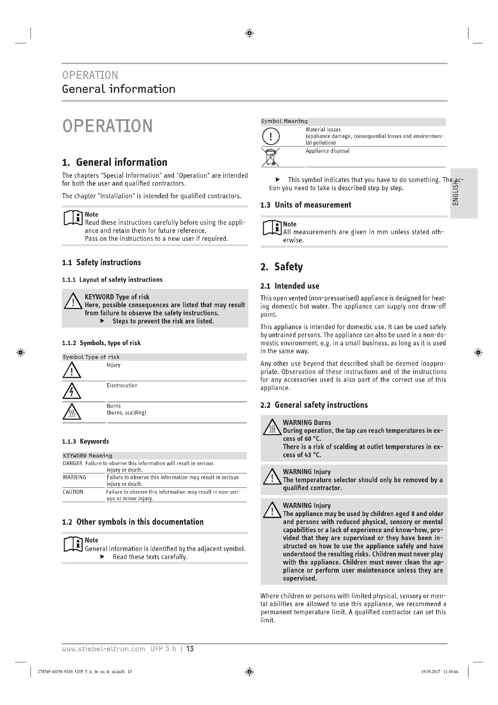
Symbol Meaning

Material losses
(appliance damage, consequential losses and environmental pollution)
Appliance disposal

This symbol indicates that you have to do something. The action you need to take is described step by step.
1.3 Units of measurement

Note
All measurements are given in mm unless stated otherwise.
2. Safety
2.1 Intended use
This open vented (non-pressurised) appliance is designed for heating domestic hot water. The appliance can supply one draw-off point.
This appliance is intended for domestic use. It can be used safely by untrained persons. The appliance can also be used in a non-domestic environment, e.g. in a small business, as long as it is used in the same way.
Any other use beyond that described shall be deemed inappropriate. Observation of these instructions and of the instructions for any accessories used is also part of the correct use of this appliance.
2.2 General safety instructions

WARNING Burns
During operation, the tap can reach temperatures in excess of 60^ .
There is a risk of scalding at outlet temperatures in excess of 43^

WARNING Injury
The temperature selector should only be removed by a qualified contractor.

WARNING Injury
The appliance may be used by children aged 8 and older and persons with reduced physical, sensory or mental capabilities or a lack of experience and know-how, provided that they are supervised or they have been instructed on how to use the appliance safely and have understood the resulting risks. Children must never play with the appliance. Children must never clean the appliance or perform user maintenance unless they are supervised.
Where children or persons with limited physical, sensory or mental abilities are allowed to use this appliance, we recommend a permanent temperature limit. A qualified contractor can set this limit.
OPERATION
Appliance description

Material losses
The user should protect the appliance and its tap against frost.

Material losses
Never subject the appliance to water pressure. The tap outlet has a vent function. Scale build-up can block the outlet and subject the appliance to pressure.
Never seal the tap outlet.
Only use special aerators for non-pressurised water heaters.
Never extend the tap outlet with a hose.

Material losses
Connecting the appliance via a time switch will cause an unintentional reset of the high limit safety cut-out.
- Never connect the appliance to the power supply via a time switch.
2.3 Test symbols
See type plate on the appliance.
3. Appliance description
The open vented (non-pressurised) appliance constantly maintains the water content at the pre-selected temperature. During heating, expansion water drips from the tap. The appliance may only be installed with taps for open vented (non-pressurised) water heaters (see chapter "Installation / Appliance description / Required accessories").
3.1 Operation
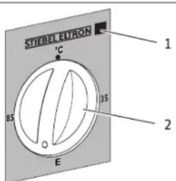
You can set any required DHW outlet temperature at the temperature selector. The heat-up indicator illuminates during the heat-up process.
D0000042210
1 Heat-up indicator
2 Temperature selector
Depending on the system, the actual temperatures may vary from the set value.
^ C = Cold. On this setting, the appliance is protected from frost. The tap and the water line are not protected.
E = Recommended energy saving setting (approx. 60^ ), minor scaling
85 = Highest selectable temperature
A qualified contractor can set a temperature limit on the appliance (see chapter "Installation / Settings / Setting the temperature limit").
4. Cleaning, care and maintenance
a Never use abrasive or corrosive cleaning agents. A damp cloth is sufficient for cleaning the appliance.
- Check the tap regularly. You can remove limescale deposits at the outlet using commercially available descaling agents.
Almost every type of water will deposit lime at high temperatures. This settles inside the appliance and affects both the performance and service life. The heating elements should therefore be descaled if necessary. A qualified contractor who is aware of the local water quality will tell you when the appliance should next be descaled.
5. Troubleshooting
| Problem Cause Remedy | ||
| The appliance does not supply hot water. | The temperature se- lector is set to "°C". | Switch the appliance ON by turning the temperature selector. |
| No power at the ap- pliance. | Check the plug and the fuses/MCBs in the fuse box/ distribution panel. | |
| Water can only be drawn at a reduced rate. | The aerator in the tap is scaled up. | Descale / replace the aer- ator. |
| Loud boiling noises in- side the appliance. | The appliance is scaled up. | Have the appliance des- caled by a qualified con- tractor. |
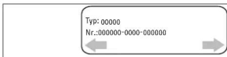
If you cannot remedy the fault, notify your qualified contractor. To facilitate and speed up your request, provide the number from the type plate (000000-0000-000000).
D0000039599
INSTALLATION
Safety
INSTALLATION
6. Safety
Only a qualified contractor should carry out installation, commissioning, maintenance and repair of the appliance.
6.1 General safety instructions
We guarantee trouble-free function and operational reliability only if original accessories and spare parts intended for the appliance are used.
6.2 Instructions, standards and regulations

Note
Observe all applicable national and regional regulations and instructions.
7. Appliance description
The open vented (non-pressurised) appliance is suitable only for oversink installation. The appliance is intended to heat cold water and supply it to a single draw-off point.
The appliance must only be installed with an open (non-presurised) tap.
7.1 Standard delivery
Delivered with the appliance are the following:
- Wall mounting bracket
7.2 Required accessories
Select an open (non-pressurised) tap that is appropriate for your requirements and equipment:
Twin-handle mixer tap
-WKM
Mono lever mixer tap
-MEK
8. Preparations
Flush the water line thoroughly.
Water installation
A safety valve is not required.
Taps/valves
Sealed unvented taps are not permitted.
Install an open vented tap.
8.1 Installation site

Material losses
Install the appliance in a room free from the risk of frost.

Material losses
Mount the appliance on the wall. The wall must have a sufficient load-bearing capacity.

Material losses
Connecting hose length (from tap to appliance) may not exceed 1 m.
For connecting hoses >1m
Install a tube aerator attachment in the overflow line.

Note
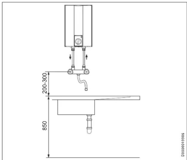
The appliance is only suitable for oversink installation. The water connections of the appliance point downwards.

Note
Ensure that the appliance is freely accessible for maintenance work.
Always install the appliance vertically and near the draw-off point.
9. Installation
9.1 Appliance installation
Mark out the holes to be drilled on the wall (see chapter "Installation / Specification / Dimensions and connections").
Drill the holes and insert suitable rawl plugs.
Secure the wall mounting bracket using suitable screws.
Hang the appliance on the wall mounting bracket.

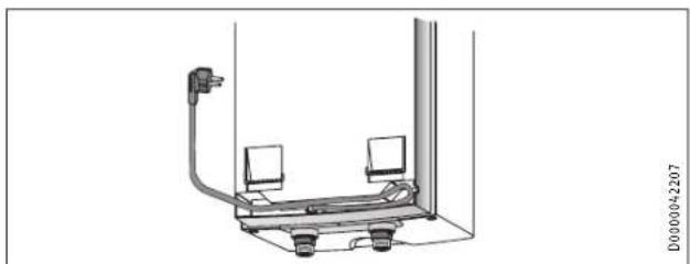
Note
Surplus cable can be stored in the cable compartment.
INSTALLATION
Commissioning
9.2 Water connection

Material losses
Carry out all water connection and installation work in accordance with regulations.

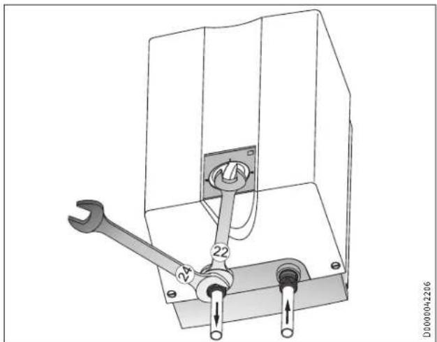
Material losses
Counterhold with a suitable spanner when tightening fittings.

Material losses
The appliance may develop a leak and cease functioning.
Never subject the appliance to water pressure.
Never interchange the water connections.
Set the flow rate (see tap instructions). Observe the maximum permissible flow rate with a fully opened tap (see chapter "Installation / Specification / Data table").

Note
The levers for the twin-lever mixer tap for oversink installation are delivered DIN 44897-compliant:
Cold water on the left (blue)
Hot water on the right (red)
- Secure the water connections from the tap to the appliance.
9.3 Power supply

WARNING Electrocution
Carry out all electrical connection and installation work in accordance with relevant regulations.

WARNING Electrocution
When permanently connected to the power supply using a dedicated junction box, the appliance must be able to be isolated from the mains power supply by an isolator that disconnects all poles with at least 3mm contact separation.

WARNING Electrocution
Ensure that the appliance is earthed.

Material losses
The voltage specified on the type plate must match the mains voltage.
Observe the type plate.
The following electrical connections are permissible:
| UFP 5 h | UFP 5 h LABS | |
| Connection to a freely accessible standard sock-et with matching plug | X | X |
| Permanent connection to an appliance junctionbox with earth conductor | X | X |
10. Commissioning

WARNING Electrocution
Commissioning may only be carried out by a qualified contractor in accordance with safety regulations.
10.1 Initial start-up
Either open the DHW valve of the tap or set the mono lever mixer tap to "hot" until the water that flows out is free of air bubbles.
Insert the plug into the standard socket or set the fuse/MCB in the fuse box.
Select a temperature.
Check the entire hydraulic installation for tightness.

Note
If you fail to follow the correct sequence (first water, then power), the high limit safety cut-out will trip.
Proceed as follows:
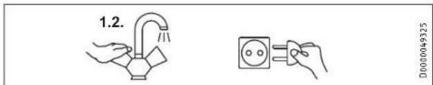
Disconnect the appliance from the power supply.
Fill the appliance with water.
Connect the appliance to the power supply.
INSTALLATION
Settings
10.1.1 Appliance handover
Explain the functions of the appliance to the user. Show the user how to operate the appliance.
Make the user aware of potential dangers, especially the risk of scalding.
- Hand over these instructions and, if applicable, the instructions for any accessories.
10.2 Recommissioning
See chapter "Installation / Commissioning / Initial start-up".
11. Settings
11.1 Setting the temperature limit
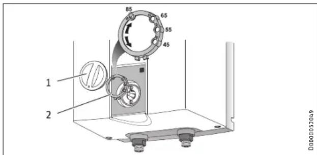
1 Temperature selector
2 Limiting ring
Placing the limiting ring behind the temperature selector allows you to limit the setting range of the temperature selector. The appliance temperature can be limited to either a maximum or minimum temperature.
The limiting ring has four holes and two end-stops around its edge. The holes are inscribed with temperature markings. Insert the limiting ring into the appliance cover so that the spike in the appliance cover pokes through one of the holes with a temperature marking. The inscription on the limiting ring must be visible after insertion.
Setting a maximum temperature of 45^ 55^ 65^
Turn the temperature selector to zero (fully anti-clockwise to "oC").
Pull off the temperature selector and the limiting ring.
- Insert the limiting ring into the appliance cover so that the spike in the appliance cover pokes through the hole with the required temperature marking.
Install the temperature selector set to zero (^)
The maximum appliance temperature is limited to the temperature indicated on the chosen hole.
Setting a minimum temperature limit >65^
- Turn the temperature selector clockwise as far as it will go (35).
Pull off the temperature selector and the limiting ring.
Insert the limiting ring into the appliance cover so that the spike in the appliance cover pokes through the hole with the 55 temperature marking.
Install the temperature selector set as far clockwise as possible (85).
The temperature can be set to between 65 and 85^
12. Shutdown
Isolate the appliance from the power supply by removing the plug or by tripping the MCB in the fuse box.
Drain the appliance (see chapter "Installation / Maintenance / Draining the appliance").
13. Troubleshooting
| Problem Cause | Remedy | |
| The appliance does not supply hot water. | The high limit safety cut-out has responded. | Remedy the cause of the fault. If necessary, replace the temperature controller. Allow the appliance to cool down. If you have isolated the appliance from the power supply, the high limit safety cut-out will be reset automatically. |
| Loud boiling noises inside the appliance. | The appliance is scaled up. | Descale the appliance. |
14. Maintenance

WARNING Electrocution
Before any work on the appliance, disconnect all poles of the appliance from the power supply.
Dismantle the appliance for maintenance work.
14.1 Draining the appliance

WARNING Burns
Hot water may escape during the draining process.
Drain the appliance via its connectors.
14.2 Opening the appliance
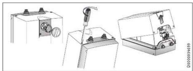
Pull off the temperature selector and the limiting ring.
- Remove the screws from underneath the temperature selector.
- Open the appliance cover by lowering the bolt screws inwards and pivot the cover upwards, then remove it.
14.3 Descaling the appliance

Material losses
Never treat the cylinder surface with descending agents.
Remove the flanged immersion heater.
Carefully tap the heating element to remove large limescale deposits.
Immerse the heating element up to the flange plate in descending agent.
14.4 Checking the earth conductor
Pull off the temperature selector and the limiting ring.
Check the earth conductor (in Germany, e.g. BGV A3) across a temperature controller fixing screw and the earth conductor contact of the power cable.
14.5 Replacing the power cable
The power cable must only be replaced by a qualified contractor with an original spare part. Alternatively, the H05VV-F3x1.0 cable may be used.
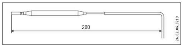
14.6 Positioning the temperature sensor in its protective pipe
- When replacing the temperature controller, guide the temperature sensor into its protective pipe.
- Secure the temperature sensor in place below the earthed plug.
15. Specification
15.1 Dimensions and connections
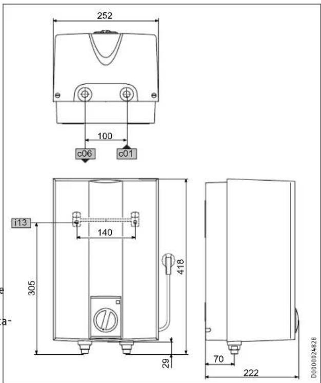
| S UFP 5 h UFP 5 h LABS | ||||
| c01 | Cold water inlet Male thread G 1/2 A G 1/2 A | |||
| c06 | DHW outlet | Male thread | G 1/2 A | G 1/2 A |
| i13 | Wall mounting bracket | |||
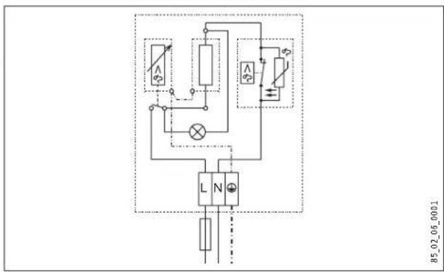
15.2 Wiring diagram
1/N/PE 220 - 240V
INSTALLATION
Specification
15.3 Heat-up diagram
The heat-up period depends on the degree of scaling and residual heat. For the heat-up time for a cold water supply at 10^ and a maximum temperature setting, see the diagram.
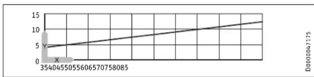
x Temperature in ^ C
y Duration in min
15.4 Country-specific approvals and certifications
The test symbols can be seen on the type plate.
15.5 Extreme operating and fault conditions
In the case of faults, a peak temperature of up to 100^ may briefly occur in the system.
15.6 Details on energy consumption
Product data complies with EU regulations relating to the Directive on the ecodesign of energy related products (ErP).
| UFP 5 h UFP 5 h LABS | ||
| 222158 | 233076 | |
| Manufacturer | STIEBEL ELTRON | STIEBEL ELTRON |
| Load profile | XXS | XXS |
| Energy efficiency class | A | A |
| Energy conversion efficiency | % | 38 |
| Annual power consumption | kWh | 491 |
| Default temperature setting | °C | 55 |
| Sound power level | dB(A) | 15 |
| Daily power consumption | kWh | 2,276 |
15.7 Data table
| UFP 5 h | UFP 5 h LABS | ||||||
| 222158 | 233076 | ||||||
| Hydraulic data | |||||||
| Nominal capacity | I | 5 | 5 | ||||
| Mixed water volume at40 °C | I | 10 | 10 | ||||
| Electrical data | |||||||
| Rated voltage | V | 220 | 230 | 240 | 220 | 230 | 240 |
| Rated output | kW | 1.8 | 2.0 | 2.2 | 1.8 | 2.0 | 2.2 |
| Rated current | A | 8.3 | 8.7 | 9.1 | 8.3 | 8.7 | 9.1 |
| MCB/fuse rating | A | 10 | 10 | 10 | 10 | 10 | 10 |
| Phases | 1/N/PE | 1/N/PE | |||||
| Frequency | Hz | 50/60 | 50/60 | ||||
| Application limits | |||||||
| Temperature setting range | °C | approx. 35-85 | approx. 35-85 | ||||
| Max. permissible pressure | MPa | 0 | 0 | ||||
| Max. flow rate | l/min | 5 | 5 | ||||
| Energy data | |||||||
| Standby energy consump-tion/24 h at 65 °C | kWh | 0.23 | 0.23 | ||||
| Energy efficiency class | A | A | |||||
| Versions | |||||||
| IP rating | IP24 D | IP24 D | |||||
| Type of installation | Oversink | Oversink | |||||
| Type | Open | Open | |||||
| Internal cylinder material | PP | PP | |||||
| Thermal insulation material | EPS | EPS | |||||
| Casing material | PS | PS | |||||
| Colour | white | white | |||||
| Connections | |||||||
| Water connection | G 1/2 A | G 1/2 A | |||||
| Dimensions | |||||||
| Depth | mm | 222 | 222 | ||||
| Height | mm | 418 | 418 | ||||
| Width | mm | 252 | 252 | ||||
| Weights | |||||||
| Weight | kg | 3.1 | 3.1 | ||||
Guarantee
The guarantee conditions of our German companies do not apply to appliances acquired outside of Germany. In countries where our subsidiaries sell our products a guarantee can only be issued by those subsidiaries. Such guarantee is only granted if the subsidiary has issued its own terms of guarantee. No other guarantee will be granted.
We shall not provide any guarantee for appliances acquired in countries where we have no subsidiary to sell our products. This will not affect warranties issued by any importers.
Environment and recycling
We would ask you to help protect the environment. After use, dispose of the various materials in accordance with national regulations.
REMARQUESPARTICULIERES
UTILISATION
Installation hydraulic
WAARSCHUWING verbranding
WAARSCHUWING verbranding
United Kingdom and Ireland
STIEBEL ELTRON UK Ltd.
Unit 12 Stadium Court
Stadium Road | CH62 3RP Bromborough
Tel. 0151 346-2300 | Fax 0151 334-2913
info@stiebel-eltron.co.uk
www.stiebel-eltron.co.uk
United States of America
STIEBEL ELTRON, Inc.
17 West Street | 01088 West Hatfield MA
Tel. 0413 247-3380 | Fax 0413 247-3369
info@stiebel-eltron-usa.com
www.stiebel-eltron-usa.com
Irrtum und technische Änderungen vorbehalten! | Subject to errors and technical changes! | Sous reserve d'erreurs et de modifications techniques! | Onder worbohoud遵守 vergisseningen en technische wizigingen! | Salvo error o modificacion tectic! | Excepto erro ou alteracao tectica | Zastrzezone zmiary technique en eventualea blde | Omlyx a techniekzme nyisou vhrazenj! | A muszki valtozatatzisk es tevedesek jgigt fennartluk! | OcyrtCTBn Ounbok he rapaHTapyctc. BoMoxKm TnckHueckne KMMEHn H Chby a techniekzme snyvhraden? Stand 9147
STIEBEL ELTRON