KSCPSW8 - Subwoofer KENWOOD - Free user manual and instructions
Find the device manual for free KSCPSW8 KENWOOD in PDF.
| Product type | Active subwoofer |
| Brand | Kenwood |
| Model | KSCPSW8 |
| Dimensions (W × H × D) | 350 × 75 × 240 mm |
| Weight | 4.5 kg |
| Power supply | DC 14.4 V (11 V - 16 V) |
| Maximum power | 250 W |
| Frequency response | 35 Hz - 150 Hz |
| Adjustable cutoff frequency | 50 Hz - 125 Hz |
| Switchable phase | 0° or 180° |
| Sensitivity | 81 dB |
| Input impedance (LINE IN) | 22 kΩ |
| Current consumption / Fuse | 10 A / 10 A |
| Speaker inputs | Yes (high level) |
| RCA inputs | Yes (low level) |
| Wired remote control | Yes (5 m) |
| Remote control functions | Volume, cutoff frequency, phase, lighting |
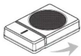
| Installation | In vehicle, on a flat and solid surface |
| Maintenance and cleaning | Soft dry cloth; do not use solvents |
| Safety | Disconnect battery before installation; use fuses of same rating |
| Included parts | Remote control, 10-pin cable (5 m), speaker cable (4.3 m), brackets, screws, hook-and-loop straps |
| Intended use | In-car audio system |
Frequently Asked Questions - KSCPSW8 KENWOOD
User questions about KSCPSW8 KENWOOD
0 question about this device. Answer the ones you know or ask your own.
Ask a new question about this device
Download the instructions for your Subwoofer in PDF format for free! Find your manual KSCPSW8 - KENWOOD and take your electronic device back in hand. On this page are published all the documents necessary for the use of your device. KSCPSW8 by KENWOOD.
USER MANUAL KSCPSW8 KENWOOD
POWERED ENCLOSED SUBWOOFER
INSTRUCTION MANUAL
CAISSON D'EXTRÉME GRAVE AMPLIFIÉ
MODED'EMPLOI
GEKAPSELTER SUBWOOFER MIT VERSTÄRKER
IHCTPYKlIa3 EKCnIyATAIi
密封式放大器附加重低音扬声器
使用说明书
English
Français
Deutsch
Nederlandds
Italiano
Espanol
Português
Pycckn
YKpaHcbKa
中文
JVCKENWOOD Corporation
Caution: Read this page carefully to ensure safe operation.
WARNING WARNING
- Before mounting or wiring etc., be sure to remove the wire from the battery minus terminal. (Not doing so can cause shorts or fire.)
- When extending the ignition, battery, or ground wires, make sure to use automotive-grade wires or other wires with a 0.75mm^2 (AWG 18) or more to prevent wire deterioration and damage to the wire coating.
- To prevent a short circuit, never put or leave any metallic objects (such as coins or metal tools) inside the speaker.
- In the event the unit generates smoke or abnormal smell, immediately switch the power OFF. After this, please contact your dealer or nearest service station as soon as possible.
POWER OFF!
- Connect the speaker to DC 12 V, negative ground.
- Do not attempt to open or modify the unit, for this could cause fire hazard or malfunction.
- After taking the unit out of the polyethylene bag, be sure to dispose of the polyethylene bag out of the reach of children. Otherwise, they may play with the bag, which could cause hazard of suffocation.
CAUTION CAUTION
- Installation and wiring of the product requires expert skill and experience. To ensure safety, be sure to have your dealer or specialist perform the installation and wiring.
- Do not install the speaker in a spot exposed to direct sunlight or excessive heat or humidity.
- Do not install the speakers in locations which may be subject to water or moisture.
- Do not install the speakers in unstable locations or locations subject to dust.
- If the fuse blows, after checking to see if the wiring cord has shorted, be sure to replace with the stipulated size (amperage) fuse as displayed on the fuse box. (Using fuses other than the stipulated size can cause fires.)
Check the display!
To replace the fuse, refer to the vehicle instruction manual.
- To prevent a short circuit when replacing a fuse, disconnect the wiring harness at first.
- Do not use gasoline, naphtha, or any type of solvent to clean the speaker. Clean by wiping with a soft, dry cloth.
- Connect the speaker wires to appropriate speaker connectors separately. Sharing the negative wire of the speaker or grounding speaker wires to the metal body of the car can cause this unit to fail.
- When making a hole under a seat, inside the trunk, or somewhere else in the vehicle, check that there is nothing hazardous on the opposite side such as a gasoline tank, brake pipe; or wiring harness, and be careful not to cause scratches or other damage.
- For ground wire mounting, do not fasten the wire to an airbag, steering or brake line system or other critical safety unit bolts or nut. (Can cause accidents.)
- When mounting, be sure to mount in a place that will not interfere with driving or be dangerous to passengers during sudden braking etc.
(Cause of injury or accidents.)
- After installing the unit, check to make sure that electrical equipment such as the brake lamps, turn signal lamps and windshield wipers operate normally.
- The driver should always stop the vehicle in a safe place before performing the following action.
Remote control operation
- Do not use the product for purposes other than on-board mounting.
- Keep the volume of sound at an optimum level. Not being able to hear sounds from outside of your car can lead to traffic accidents.

Declaration of Conformity with regard to the EMC Directive 2014/30/EU Declaration of Conformity with regard to the RoHS Directive 2011/65/EU
Manufacturer:
JVC KENWOOD Corporation
3-12 Moriya-cho, Kanagawa-ku, Yokohama-shi
Kanagawa, 221-0022, JAPAN
EU Representative:
JVCKENWOOD Europe B.V.
Information on Disposal of Old Electrical and Electronic Equipment (applicable for countries that have adopted separate waste collection systems)
Products with the symbol (crossed-out wheeled bin) cannot be disposed as household waste. Old electrical and electronic equipment should be recycled at a facility capable of handling these items and their waste by products.
Contact your local authority for details in locating a recycle facility nearest to you. Proper recycling and waste disposal will help conserve resources whilst preventing detrimental effects on our health and the environment.
For U.S.A.
FCC WARNING
This equipment may generate or use radio frequency energy. Changes or modifi cations to this equipment may cause harmful interference unless the modifi cations are expressly approved in the instruction manual. The user could lose the authority to operate this equipment if an unauthorized change or modifi cation is made.
FCC NOTE
This equipment has been tested and found to comply with the limits for a Class B digital device, pursuant to Part 15 of the FCC Rules. These limits are designed to provide reasonable protection against harmful interference in a residential installation. This equipment may cause harmful interference to radio communications, if it is not installed and used in accordance with the instructions. However, there is no guarantee that interference will not occur in a particular installation. If this equipment does cause harmful interference to radio or television reception, which can be determined by turning the equipment off and on, the user is encouraged to try to correct the interference by one or more of the following measures:
- Reorient or relocate the receiving antenna.
- Increase the separation between the equipment and receiver.
- Connect the equipment into an outlet on a circuit different from that to which the receiver is connected.
- Consult the dealer or an experienced radio/TV technician for help.
| No. | Part Name Outside Shape | Quantity No. Part N | Name Outside Shape | Shape Quantity | ||
| ① | Remote control(5 m/16 ft) | 1 | ⑥ | Tapping screw(ø 5 x 16 mm (5/8")) | ||
| ② | 10-pin connector cord(5 m/16 ft) | 1 | ⑦ | Machine screw(M4 x 16 mm (5/8")) | ||
| ③ | Speaker cord(4.3 m/14 ft) | 1 | ⑧ | Tapping screw(ø 3 x 10 mm (3/8")) | ||
| ④ | Fixture A 2 | ⑨ | Hook-and-loop fastener(Double-side adhesive/for Remote control) | |||
| ⑤ | Fixture B 1 |
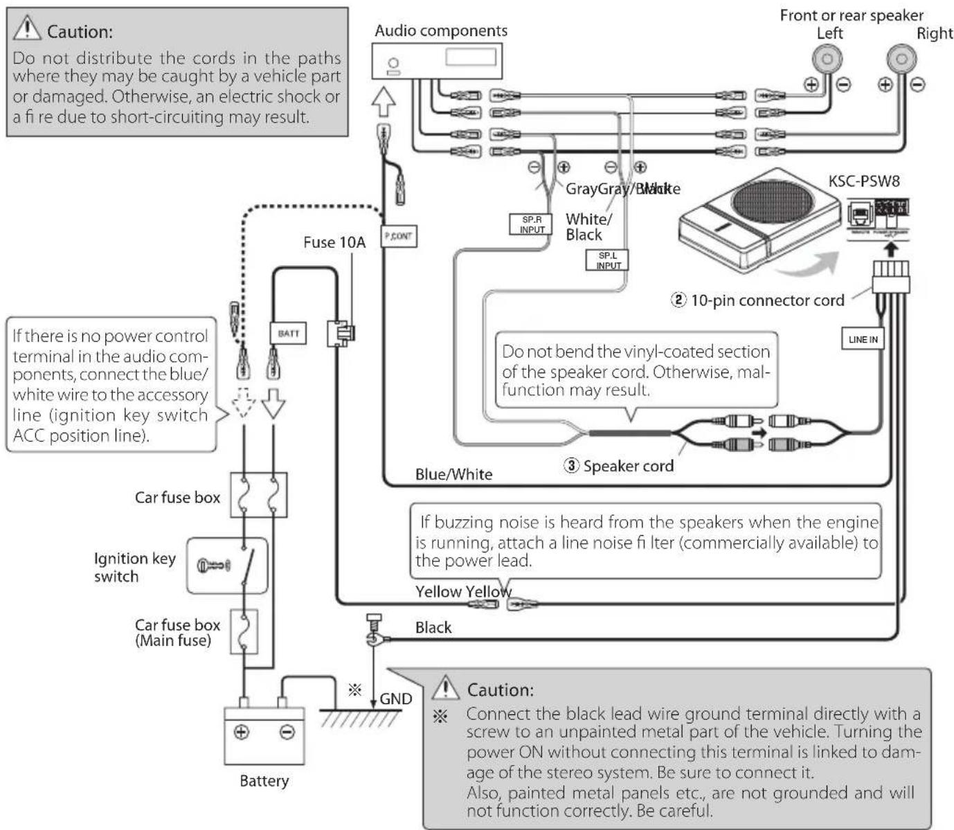
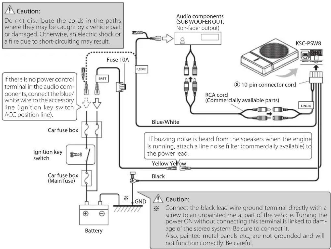
Connections

Caution:
Before wiring, be sure to remove the wire from the negative terminal of the battery. After completing all wiring, check the correct wirings again. After checking, connect the wire from the negative terminal of the battery.
Terminals of Subwoofer
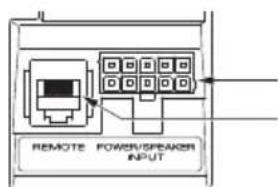
POWER/SPEAKER INPUT terminal REMOTE terminal
- Connecting the remote control unit
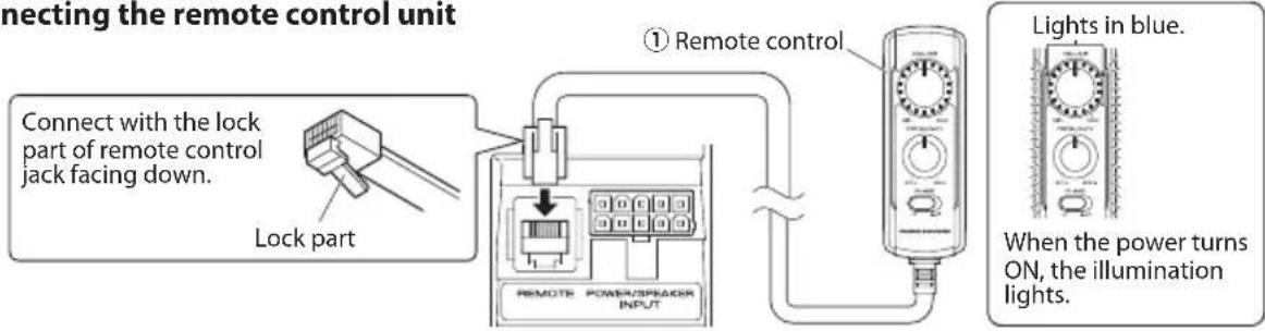
Notes:
- Be sure to connect the supplied remote control unit.
- If the cord is not connected properly, the illumination on the remote control unit do not light up.
- Do not insert the remote control connector upside down or forcibly. Otherwise, malfunction may result.
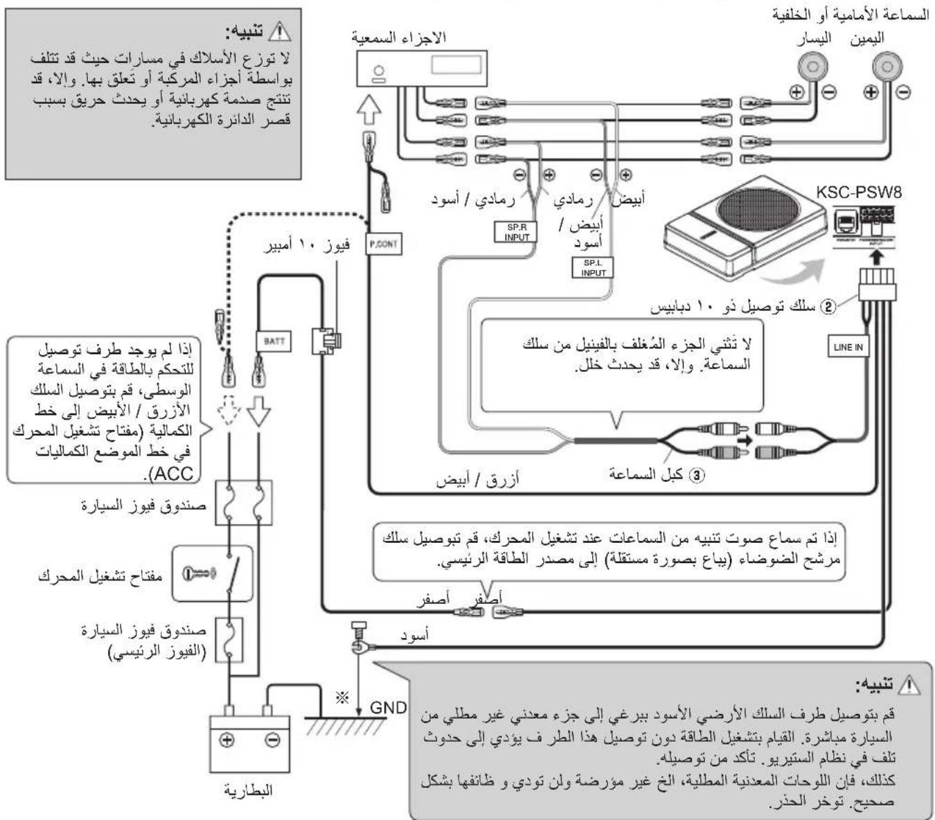
Speaker input connection
Connect the subwoofer to the front speaker or rear speaker output cords of the audio components.
Notes:
- Read the instruction manuals for the connected components such as the audio components as well as this instruction manual.
- In a computer-equipped vehicle, when you remove the terminal of the battery, the memory may disappear, or a defect may occur in the electrical system of the vehicle. Consult your dealer for further details.
- When the audio components incorporate a DSP, do not connect to the rear output, as the low-frequency reproduction effect may be attenuated due to the DSP effect.
Example
The following shows a typical connection for effective car stereo enjoyment. Connect your system by referring to the example.
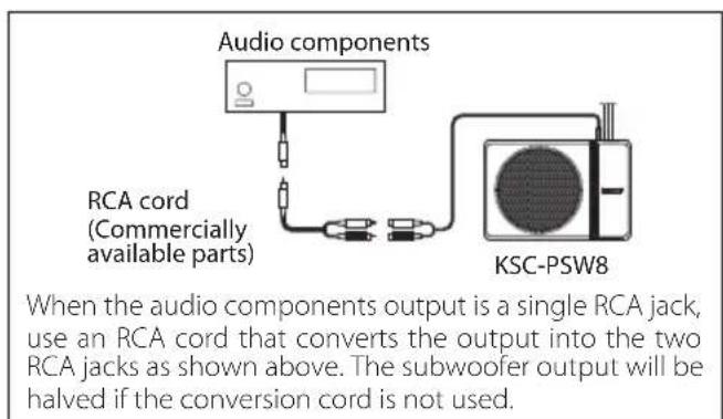
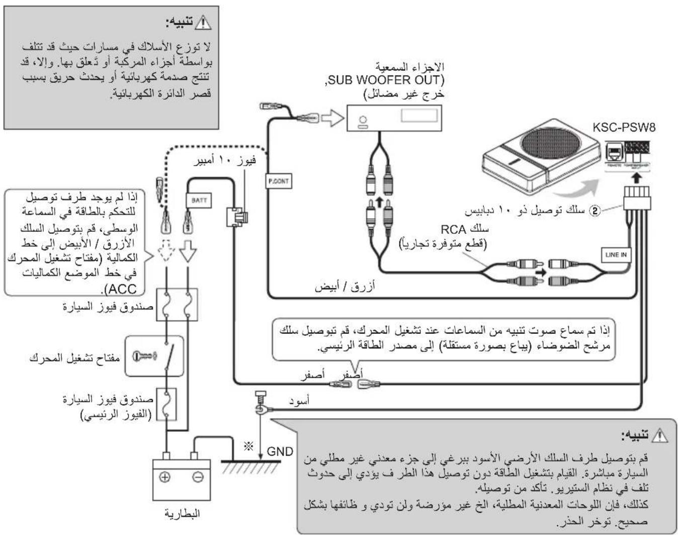
RCA input connection
Connect the subwoofer to the subwoofer output (non-fader output) or the RCA jacks for the front output of the audio components.
Notes:
- Read the instruction manuals for the connected components such as the audio components as well as this instruction manual.
- In a computer-equipped vehicle, when you remove the terminal of the battery, the memory may disappear, or a defect may occur in the electrical system of the vehicle. Consult your dealer for further details.
- Please purchase an RCA cord that is commercially available separately.
- When the audio components incorporate a DSP, connect the subwoofer to the subwoofer output (non-fader output) or to the RCA jacks for the front output. Do not connect to the RCA jacks for the rear output, as the low-frequency reproduction effect may be attenuated due to the DSP effect.
Example
The following shows a typical connection for effective car stereo enjoyment. Connect your system by referring to the example.
Before fixing the speaker in its position, be sure to check the sound while it is connected preliminary.

Caution:
- When making a hole under a seat, inside the trunk, or somewhere else in the vehicle, check that there is nothing hazardous on the opposite side such as a gasoline tank, brake pipe; or wiring harness, and be careful not to cause scratches or other damage.
Install in a location that does not come in the way of driving, getting in or out of the vehicle and movement inside the vehicle compartment.
Fix the product firmly so that it will not be moved by vibrations or impacts during driving.
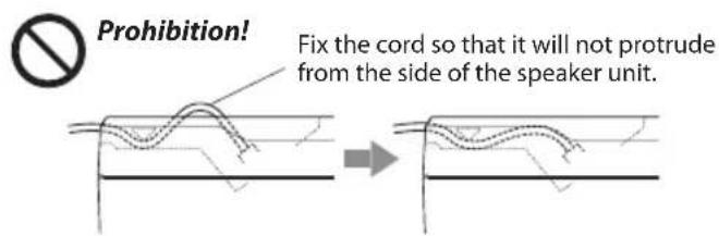
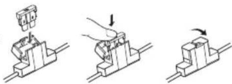
Fixing the cord in place
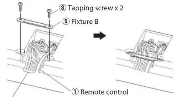
② 10-pin connector cord
1 Connect the 10-pin connector cord ② and remote control ① to the speaker unit.
Fix the cords to the speaker unit with fixture B 5 and fix in place with the tapping screws 8.
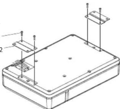
Fixing the subwoofer
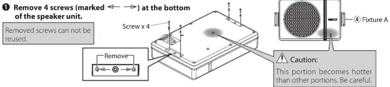
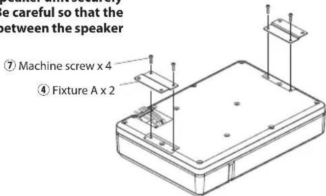
Attach the fixtures A ④ to the speaker unit securely using the machine screws ⑦ . Be careful so that the connected cords do not get in between the speaker unit and fixtures A ④
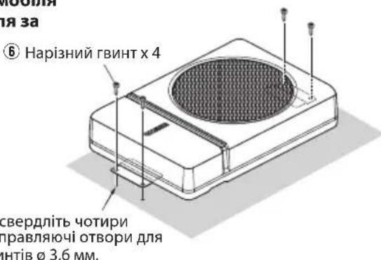
3 Drill the pilot holes for 3.6mm(1 / 8^ ) screws on the sheet metal section of the vehicle, and attach the speaker unit to the vehicle using the tapping screws ⑥
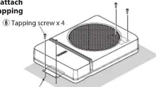
Drill four pilot holes for 0.36mm(1 / 8^ ) screws.
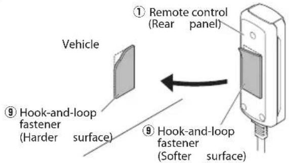
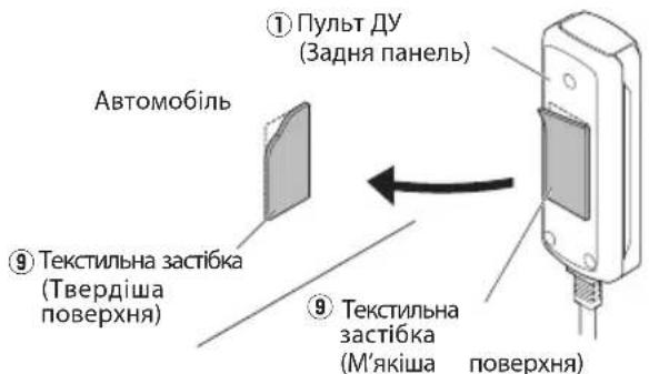
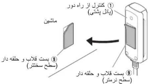
■ Installing the remote control unit Install the remote control unit on the vehicle by the provided hook-and-loop fastener.
Caution:
Install the remote control unit in a position that does not come in the way of driving operations.
Avoid installing it in a place subject to direct sunlight or direct hot wind from the heater. Otherwise, the product may be degraded and a fire hazard may result.
Remove dirt from the installation position before attaching the hook-and-loop fastener.
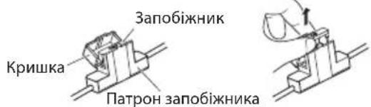
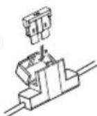
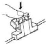
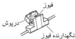
Fuse exchange
Exchange with the specified capacity fuse.

Caution: Be sure to replace with same capacity (amperage) as displayed on the fuse. This product is 10A.
■ Removal Insertion
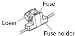
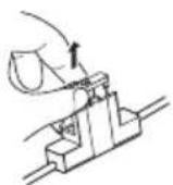
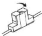
1 Open the cover.
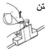
Grasp the fuse and pull up.
Replacement fuse 10 A
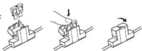
Insert the fuse gently into the fuse holder and push in all the way with your finger.
Close the cover.
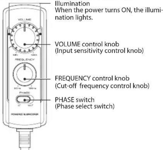
Operation
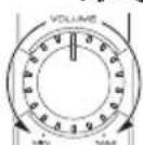
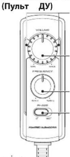
Name of each part (Remote control)
Note:
Large power input will cause the protection circuit for this unit to operate, which will decrease output level. In this case, turn the volume to "MIN" for a while, then eventually this unit will automatically start working again.
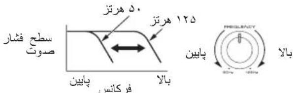
The sound is output even when the remote control unit is not connected, but the operations described in this section are not available. In this case, the volume, cut-off frequency and phase are set to the predetermined default conditions, with which the cut-off frequency is 125Hz and the phase is 0^ (positive).
Adjusting the sound
(Remote control operation)
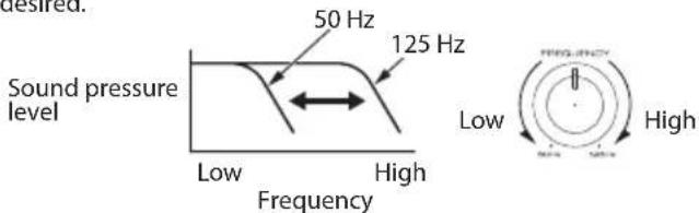
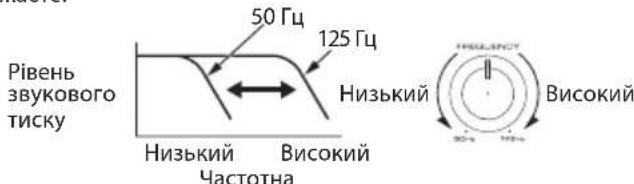
1 Turn the FREQUENCY control knob to adjust the cut-off frequency (frequencies higher than this frequency are cut off).
Turn the FREQUENCY control knob to adjust the balance between the bass from the rear speakers and the bass from this unit as desired.
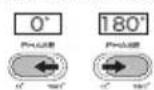
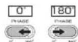
Adjust the low frequency phase.
The low frequency tone may be variable depending on the position of the unit, its orientation or the turn-over frequency. This can be adjusted by changing the position of the PHASE switch. Set this switch to either position according to your liking. [0^] indicates the normal phase and [180^] means the reverse phase.
③ Turn the VOLUME control knob to adjust the low frequencies to the desired level.
To decrease volume
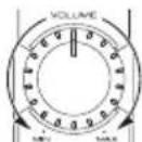
To increase volume
Often, what appears to be a malfunction is due to user error. Before calling for service, please consult the following table.
| Problem Cause Remedy | ||
| Power cannot be turned on (illumination does not light). | ·The fuse is blown. | ·Check the ⊕/ ⊙ polarity of the power cord and that the cords are not shorted, then replace with a fuse with the rated capacity. ·Re-connect the cords correctly by referring to the connection example (on page 4, 5). |
| ·The power supply pin (yellow) of the 10-pin con- nection cord is not connected. | ·Connect the cord correctly by referring to the connection example (on page 4, 5). ·Attach the grounding terminal to the metallic section of the vehicle (not a coated surface) by tightly screwing it. ·Insert the connector all the way in. ·Check the connections of all cords, then connect the ⊙ cable to the battery. | |
| ·The power control pin (blue/white) of the 10-pin connection cord is not connected. | ||
| ·The grounding pin (black) of the 10-pin connec- tion cord is not connected. | ||
| ·The 10-pin connector is not plugged in completely. | ||
| ·The negative ⊙ cable of the car battery is discon- nected. | ·Check the connections of all cords, then connect the ⊙ cable to the battery. | |
| No sound | ·The attenuator of the audio components is set to ON. | ·Switch the attenuator OFF. |
| ·The VOLUME control is set to the MIN position. | ·Increase the volume to an optimum level (on page 7). | |
| ·The speaker cords are connected improperly. | ·Connect the cords correctly by referring to the connection example (on page 4). | |
| ·Connection terminals are connected improperly. | ·Insert the connectors or jacks all the way in to the terminals. | |
| Sound is small. | ·The input level is set to low. | ·Turn the VOLUME control knob and set the input level to an optimum level. |
| ·Connection terminals are connected improperly. | ·Plug the cord into the REMOTE terminal. ·Check that the RCA cord is connected properly. | |
| ·Large power input causes the protection circuit for this unit to operate. | ·Turn the volume to MIN for a while. | |
| Sound quality is bad (sound is distorted). | ·The input level is set to high. | ·Turn the VOLUME control knob and set the input level to an optimum level. |
| Sound is unnatural. | ·The speaker cords are connected with incorrect positive ⊕/negative ⊙ polarity. | ·Connect the cords correctly by referring to the connection example (on page 4, 5). ·Attach the grounding terminal to the metallic section of the vehicle (not a coated surface) by tightly screwing it. |
| ·The grounding pin (black) of the 10-pin connec- tion cord is poorly contacted. | ||
| Remote control does not work. | ·The remote control cord is unplugged. | ·Plug the cord into the REMOTE terminal. ·Insert the connector all the way in. |
| The illuminations on the remote control unit do not light. | ||
Specifications
Design and specific cations are subject to change without notice.
Maximum output 250 W
Frequency response 35 Hz-150 Hz
Cut-off frequency 50 Hz-125 Hz
Phase 0,180
Input sensitivity / impedance
LINE IN 125 mV/22 kΩ
Power DC 14.4 V (Operating voltage 11 V-16 V)
Current consumption 10 A
Sensitivity 81 dB
Dimensions Width : 350 mm (13-3/4")
Height: 75mm (2-15/16")
Depth: 240mm (9-7/16")
Weight 4.5 kg (9.9 lb)

JWC KENWOOD Corporation
3-12 Moriya-cho, Kanagawa-ku, Yokohama-shi,
Kanagawa, 221-0022, JAPON
IpeCTaBtEnbCTBOB EC:
JVCKENWOOD Europe B.V.
BnKpyeHi TBuHTN He MoXHa BnKOpNCTOByBaTNI NOBTOPOHO.
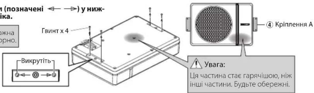
2PiεdHaHTe KpInnEHAA 4do dHamaKa Ta HadiuHO 3aTARHtB 3a DOnOMoIO KpinunbHnx rBuHTIB. BybTe o6epexHi, 0o6 niεdHaHI Ka6eni He nonaann mix dHAmikom Ta KpinnenHnMa A 4.
⑦ KpinnbHn rBnHT x4 ④ KpinneHHA x2
BucbepnItb HanpaBnaHoyi OTBOp nIra rBnHTIB 3,6 MM Ha iinrHci IncTOBO r Metany ABTOMo6i n iip'ecHaHte 6loK dINHAMiKa Jo ABTOMo6iHa donOMOrIO Hap3Hn rBnHT 6.
BcTaHOBLeHH npucTpoU dncTaHuiHoro KepyBaHHa
BctahOBiB npncptpi dnctAHcHOro KepyBaHHHa ABTOMo6Ib 3a donomoroTo TeKCTnIbHOi 3actio.
3amiHa 3an06ixHnka

yBara:
BctaHObit npntpiinntaHnHOro KepyBaHH B noJooXeHH, aKe He 3aBaKaTmE KepyBaHHIO.
He cnid BCTaHOBIOBaTu NOro B Micu, 10 Niinrae npMOMy coHnHOMy cBiTy a6o npMOMy rapuOMy nobitpio BiHarpibaya. B iHOMy BnauKy, CTah npOdykTu MoKe 6ytN noripweHn, 10 MoKe cnpuHHInTu NoKexy.
BnanaTb 6pyd 3 Micu yctahOBKn nepei Tm k npknpinTN TeKCTnblHy 3acti6ky.
3aHa 3anO6iXHKOM Bn3Ha-yeHOI EMHOCTI.

Ybara: O6OB'3KOBO 3aMIHIOHTe Ha Ty camy EMHICTb (Cnny CTPMy), kky NOKa3aHO Ha 3a-no6iKHKy. DaHn npOdyKT - 10 A.
■BudaneHHy UcTaHOBka
Bikpnite Kpwnky.
Bizbmitcbca 3a 3ano6ixhnik i notarHtB bropy.
YnpabbliHn

3anachn 3anobixhNK 10A
06epexkHO BCTaBte 3ano6ixHnK y TpImau 3ano6ixHnKa i HATNCiTb nabueM NO Bci nnounHi.
3akpuTe KpnuKy.
Ha3Ba KoxHoi YaCTMH
PiicBiyBaHHaKoPi npCtpi BMkaetbca,3aropaeTbcnCiuyBaHH.
Pyuka peryIIOBaHHa VOLUME (Pyuka peryIIOBaHHa yTnIOBOCTI BBOdy)
PyuKa perynIOBaHHFREQUENCY (PyuKa perynIOBaHHH qactOTn BiDiKaHH)
Ipeemkaq PHASE (Ipeemkaq B60py 4a3n)
Пурмитka:
BéniKa BxīdHa NoTyKHiCTb Ipn3Bepe Do cnpaIIOBaHH cxEM 3axncty cIbero npIcTpoH, IIO 3MeHunltb pIBeH bXiINHO CnHany. y TaKOMy pa3i Ha deAkyac yCTaHObitb ryHlCTb y NINOKeHHA《MIN》,nicra YORI CEI npIcTpi ABTOMATNUHO NOHe IpaIIOBAITN 3HOBy.
3BYK BIVBOIDnTbC, HABITb JAKUO npNCTIINCTAHIINHO KepyBaHH He NiEaHHO, Ane Oepaui, ONscAHIBcBOMy PO3dini, Heoctyni. YcbOMy BUNaIKYrHuHCTb, cactota BiDcikAHHa Ta a3a BCTaHOBNIOUTbcra 3a 3AMOBuBaHHM, B JkNx cactota BiDcikAHncklaJae 125 T4, a a3a DOpIBHIOE 0^ (no3NTNBHa).
PerylIOBaHHa 3ByKy
(OnepaiaI dncTaHciHoro KepyBaHH)
1 Nobephitb perynIaTOP FREQUENCY dIypeynIOBaHHaCTOTN BiDcKaHHe (caCTOTN BIIe, HIX cHaCTOTA BiDcKaIoTBc).
PObepHb terpyrnapFREQUENCY uo6 hanauTyBaTu 6aHaHc mix 6acom i3 3aHix dHnAmikib Ta 6acom 3 zuoro npncTpo, R6 baxkaTe.
3 HanaTyuTe Hn3bKoAcToTHy a3y.
Hn3bkoactOTTHI TOHaJIbHn CnIHaJI MoXe 3MIHOBaTnCBAJExKHOCTi BID NOLOKeHH npICtpoIO, IORO opIEHTaUi a60 cAchToN o6epTaHH. Ce MOxE 6yTN HanaWTOBaHe 3a DonOMoRO 3MINI NOLOKeHH nepemKaqA DA3N. BCTaHObit ce nepeemKaqA B 6yd-bkY No3nUio 3a BaWNM 6kaHHm.
[0°]no3Haaye HopMaIbHy a3y,a [180°]o3Haaye 3BOpOTHy a3y.


3 Nopbephitb pyuky perynaytopa VOLUME 606 BiDperyIIOBAtu H3bKi yactOTu y notpi6He noJXeHHA.
Uo63MeHUNrIyHlCTb
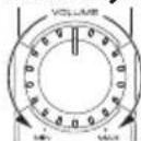
Uo636inbunr ruyHCTb
YacTo Te, 3daTbcra HecnpaBHCIO c NOMUkoIO KOpNCyBaau. Ipeed 3BepHeHHaM Do cepBichoro ceHTpy, nepeBipTe HaCTynHy Ta6nio.
| Hecnpabnosti Пччпа | Cnoci6 усуненя | |
| Жиьменна He мося 6уту вимкн'tим (пдсву-bанна He CBITNB). | 3anobixhik BmshOB 3 naу. -Пepebipte поларырсь | Ф/Кабелю Кбileн�. Я.TаСОж ВIDСТИСТь KOPOTKOrO 3amKAn- нг,notIM 3amHITb Ha 3anobixhNK HOMHaJIb- HoINotyXHocI. 3HOу NpdklIOUcTb Ka6elI NaLeJxHm ChINOM, KepyuOCHb PnIKLAdOM 3'EDHANHn (Ha CTOp. 60,61). |
| 5Tekep JxivbneHn (KoBtM) 10-KoHTaKTHo- ro 3'EDHyBaIbHOrO Ka6elI He NiKIIQUe- Hn. | ПДКЛIOUч TбКeБнн HalexHm CUnHOM, Kepyu- чсь PnIKLAdOM 3'EDHANHn (Ha CTOp. 60,61). ППрКPлIOч 3azEMLIOUChу KLEmy Do MeTaNBoI dIraHKn ABTomO6Inn (NobepxHb 63 NOKPITTTA), SILbHNo PrinTCHyBShn II TBHNTOM. ВCTaBte po3'EM NOBHCtIO. Пepebipte πidKlIOUeHn BCIX Ka6elIB,notIM Ta KI'EDHainrTe Ka6elBdo AkymunlToPA. | |
| 5Tekep KepyBaHnja JxivbNeHn (CnH/ BiH) 10-KoHTaKTHOrO 3'EDHyBaIbHOrO Ka- 6eHNo He NiKIIQUeHn. | ||
| 5Tekep 3aZemLeHn (YorHn) 10-KoH THoro 3'EDHyBaIbHOrO Ka6elIO He NiKIIQUeHn. | ||
| 10-KoTakTnHn po3'Em NpdklIOUeHn He NobHICrTO. | ||
| HeratubnHn Φ KabeIb abTomO6IbHOrO akymujIbTopa BiD'EDHAnHn. | Пepebipte πidKlIOUeHn BCIX Ka6elIB,notIM piD'EDHainrTe Ka6elB do AkymuJYTopa. | |
| Hema€ 3byk | ATteHIOaTOp aydiokomnoHenty BCTahOBHe- HO B noLoJenHn ON. | ВиMHKNITb atteHIOaTOp. |
| PeryIaTOp VOLUME BCTaHOBLeHn y noLo- JenHn MIN. | 36iNbStb ryHicTb Do onTImaIbHorO pIBHn (Ha CTOp. 63). | |
| Ka6eI DiHAMiKIB NpdklIOUeHn HnpeBaHlb- HO. | ПДКЛIOUч TбКeБнн HalexHm CUnHOM, Kepyu- чсь PnIKLAdOM 3'EDHANHn (Ha CTOp. 60). | |
| 3'EDHyBaIbHn KiMe n PiDKlIOUeHn Hnpea- BnIbHO. | ВСтаве роз'EMS ab60 rHizda B KIeMe n NobHl- CTIO. | |
| 3Byk cna6kn. | ВСтановлелн Hi3bKn PiBeHb BxIDHORO CunHany. | ПОberpHtB руЧу рergлета VOLUME Ta BCTaHOBtB PiBeHb BxIDHORO CunHany Ha ONTI- MaJIbHn PiBeHb. |
| 3'EDHyBaIbHn KiMe n PiDKlIOUeHn Hnpea- BnIbHO. | ПД'ЕДайе Унчр Do REMOTE KIeMeN. Пepebipte,ч NiD'EDHaHOb Ka6eB RCA NaEx- Hm QUnHOM. | |
| ВeIINA BxIDHa NotyKHeCTb PnIzBoDnTb do CnpaUOBaHnry CxEH M 3axNCTU cyBO rpo- STPOI. | Нa DeRaKm Yac UctaHOBt B ryHicTb y noLo- JeHnMin. | |
| Якіст bЗуку norana (Зук deфор mobaHи). | ВСтановлелн Bvscokn PiBeHb BxIDHORO CunHany. | ПОberpHtB руЧу рergлета VOLUME Ta BCTaHOBtB PiBeHb BxIDHORO CunHany Ha ONTI- MaJIbHn PiBeHb. |
| 3Byk He npripondni. | Ka6eI DiHAMiKIB NiD'EDHani 3 He nprabu- HIOU No3IITbHIOU ÷/HeRaTbHIOU ÷ IЯрHICrTO. | ПДКЛIOUч TбКeБнн HalexHm CUnHOM, Kepyu- чсь PnIKLAdOM 3'EDHAnHn (Ha CTOp. 60,61). ПprKpInITb 3aZemLIOUchу KIeMy Do Metanbeoi dIraHKn ABTomO6Inn (NobepxHb 63 NOKPITTTA), Ta ⅡЛьно PrinTCHyBShn II GBNTOM. |
| 5Tekep 3aZemLeHn (YorHn) 10-KoH THoro 3'EDHyBaIbHOrO Ka6eIIO nOraHn 3'ED- HnHi. | ||
| Ппstрий дмstанцiHо КерУвань He npaioe. | Ka6eI PiNcTPOI DmStanziHOrO Kepy- BaHn BIl'EDHAnO. | ПiD'EDHai Te Shyp Do REMOTE KIeMeN. ВСтаве роз'EMS nobHICrTO. |
| Пдсвчань Na npri- stroi dmestaniiHorO Ke- pyBaHnry He CBITNB. |
TexhiHi xapaKTepeNtIKn
KoHCTpykui Ta xapaKTePncTmKMOkyb 3MIHOBaTnC6e3 nonepdKeHHa.
MaKcmaJIbHa BnIXiHa noTyXHicTb 250 BaTT
YactoTHa xapaKTePcTnKa 35 T-150 T
YacToTa BiDciueHHra 50T-125T
Φa3a 0,180°
Bxinda ytmbicb / impeancy LINE IN 125 MB/22K
XnBHeHHa 14,4 B noctiHoro ctpymy
(Po6oua Hanpyra 11-16 B)
EheprocnoxnBaHH 10A
Uyttnubictb 81 d6
Po3mipu.. 350 MM
Bucota:75MM
TIN6HnA:240MM
Bara 4,5 k
= - 35
1 1 1 1 1 1 1 1 1 1 1 1 1 1 1 1 1 1 1 1 1 1 1 1 1 1 1 1 1 1 1 1 1 1 1 1 1 1 1 1
a 1
RCA
RCA 1 (Jzg) G a j g
S BCA = S COD + S_ BDO
1 1 1 1 1 1 1 1 1 1 1 1 1 1 1 1 1 1 1 1 1 1 1 1 1 1 1 1 1 1 1 1 1 1 1 1 1 1 1 1 1 1 1 1 1 1

a

RCA 10000000000000000000000000000000000000000000000000000000000000
4
PQ = 2
pao 4
p5 1.0
10
10 10
jia 140-0.
- 1
法式
gglg/10g 140 LINE IN
1
#
j 1 j 1 j 1 j 1 j 1 j 1 j 1 j 1 j 1 j 1 j 1 j 1 j 1 j 1 j 1 j 1 j 1 j 1 j 1 j 1 j 1 j 1 j 1 j 1 j 1 j 1 j 1 j 1 j 1 j 1 j 1 j 1 j 1 j 1 j
( 2x - 2 + 2) = 35
jol j 1 j j j j j j j j j
- iS 89
j01 juiis
i 1
1
jI 1515 jIiJalal 12 JgJy JgJy
iio 12y jy jy jy jy
(.)
s j s j s s s s s s s s s s s s s s s s s s s s
slaai jilai jj j j j j j j j
(AWG 18) jiajaiy, yds
jI jI y Ss i 1 sii 1 sii
- j 5
1 1
ydoa jy JyJoo Joo Joo Joo Joo Joo Joo Joo
1yds
15
yLj 15 jS jn jni jki jki jki jki jki jki
j 1
1j jdsLus Lai jldy 2000 j0000000000000000000
gai yia 15.15
blody
Juaia 4jz jia jia jia jia jia jia jia jia jia
=
jol jjis olus
gj jyol jj jss oik jydi y
12is aai 4jai 4iug
jg
1
C 45
2
j 1
1
1
- 1.2.3.4.5.6.7.8.9.10.11.12.13.14.15.16.17.18.19.20.21.
1
2
1
2
S LAC = S COD + S BOC - S BOC
()
1
,
C
1 1
2
j 1 j 1 j 1 j 1 j 1 j 1 j 1 j 1 j 1 j 1 j 1 j 1 j 1 j 1 j 1 j 1 j 1 j 1 j 1 j 1 j 1 j 1 j 1 j 1 j 1 j 1 j 1 j 1 j 1 j 1 j
[180°] jj 0
1 1
1 1
1 1