GT5000 - Turntable YAMAHA - Free user manual and instructions
Find the device manual for free GT5000 YAMAHA in PDF.
| Product Type | Turntable |
| Brand | YAMAHA |
| Model | GT5000 |
| Drive Method | Belt Drive |
| Motor | 24-pole, 2-phase AC synchronous |
| Speeds | 33 1/3 rpm, 45 rpm |
| Speed Variation | ±0.1% |
| Wow and Flutter | 0.04% max (W.R.M.S.) |
| Platter | Aluminum, 350 mm diameter |
| Sub Platter | Brass, 143 mm diameter |
| Tone Arm | Static balanced straight arm, effective length 223 mm |
| Overhang | -17 mm |
| Supported cartridge weight (with headshell) | 16-23.5 g |
| Headshell weight | 14 g (including wires) |
| Audio Outputs | PHONO OUT (RCA) × 1, PHONO OUT (XLR) × 1 |
| Power supply (U.S. and Canada model) | AC 120 V, 60 Hz |
| Power consumption during play | 15 W |
| Power consumption at stop | 0.4 W |
| Weight | 26.8 kg |
| Dimensions (W × H × D) | 546 × 223 × 411 mm (with feet and protrusions) |
| Operating temperature range | 10-35 °C |
| Supplied accessories | Platter, sub platter, platter covers (×2), 45 rpm adapter, control cover, handles (×2), strobe disc, power cord, 2.5 mm Allen key, owner's manual, safety brochure, supplement, cable tie, washer |
| Maintenance | Clean with soft cloth; diamond stylus with soft brush or special cleaner |
Frequently Asked Questions - GT5000 YAMAHA
User questions about GT5000 YAMAHA
0 question about this device. Answer the ones you know or ask your own.
Ask a new question about this device
Download the instructions for your Turntable in PDF format for free! Find your manual GT5000 - YAMAHA and take your electronic device back in hand. On this page are published all the documents necessary for the use of your device. GT5000 by YAMAHA.
USER MANUAL GT5000 YAMAHA
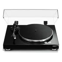
Congratulations on your purchase of this Yamaha product!
Features
This is a turntable for playing analog records.
◆ Massive yet elegant heavy wooden chassis effectively serve to dampen vibration
◆ Large, heavy double-structured platter for enhanced stability and performance
◆ Custom belt-drive mechanism driven by 24-pole, 2-phase AC synchronous motor
◆ Short, straight tonearm designed to deliver superior rigidity as well as a balanced weight
◆ Specially-designed custom feet
◆ XLR balanced output jacks that enable end-to-end balanced signal transfer from cartridge to speaker
Before you start
About this manual
This manual explains how to set up and operate this unit. When reading this manual, please note the following:
- To use the product properly and safely, we suggest that you read this manual and the included Safety Brochure thoroughly. Keep the manual in a safe, accessible place for future reference.
- Specifications and appearance are subject to change without notice in order to improve the product.
• The illustrations in this manual are for instructional purposes only.
• Explanation of graphic symbols used in this manual:
| Symbol Description | |
 WARNING WARNING | Indicates points that you must observe to avoid risk of death or serious injury. |
 CAUTION CAUTION | Indicates points that you must observe to avoid risk of injury. |
| NOTICE | Indicates points that you must observe to avoid damaging the product or causing it to malfunction. |
 | Indicates supplementary information that you may find useful. |
Table of contents
Features . . . . . . . . . . . . . 5Playing a record . . . . . . . 22
Starting the record .....22
Pausing the record 23
Stopping the record 23
About this manual 6
Checking the supplied accessories . . . 8
Part names .....10
Getting ready ..... 13
Location 13
Assembly 14
Assembling the unit ..... 14
Installing a cartridge 16
Making connections .....17
Making adjustments .....19
Adjusting the stylus pressure ..... 19
Adjusting the tonearm height ..... 20
Turning the power on . . . . . . . . . 21
When necessary ..... 24
Checking the speed .....24
Care 24
Replacing the belt. . . . . . . . . . . 25
Troubleshooting .....26
Appendix 28
Specifications ..... 28
Checking the supplied accessories
Make sure that all items are present.
Note
- Store the packaging materials, such as the packing box. If you relocate, you will need these materials to safely transport this product. Refer to the “Supplement” in the package for information on how to re-pack the product.
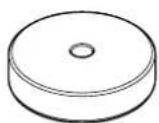
- Platter × 1
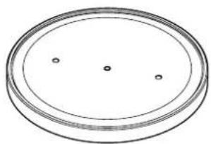
natural_image
Simple line drawing of a circular object with three small dots on its surface (no text or symbols)-
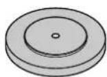
Sub platter × 1

-
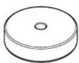
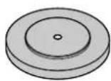
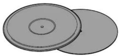
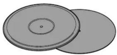
Turntable mat × 2

natural_image
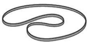
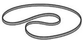
Two overlapping circular objects with concentric rings and a central dot (no text or symbols)- Belt ×1 • Counter weight ×2

natural_image
Abstract curved line drawing with no text or symbols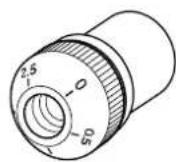
Large
Small
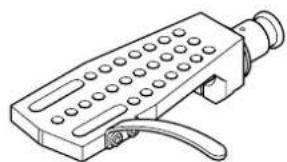
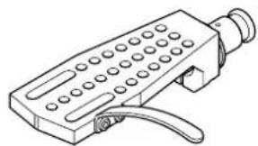
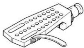
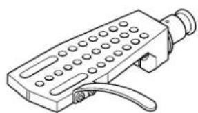
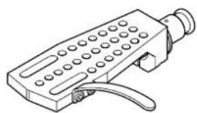
- Head shell ×1
natural_image
Line drawing of a handheld electronic device with ports and a handle (no text or symbols)-
45 rpm adaptor ×1
-
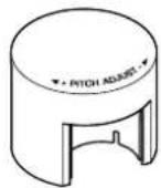
Dial cover × 1
-
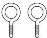
Handle × 2
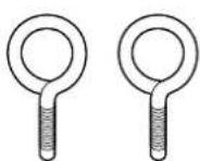
-
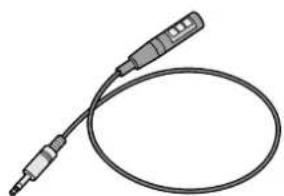
Stroboscopic disc × 1
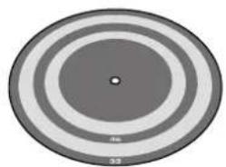
natural_image
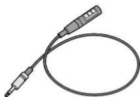
Circular diagram with concentric rings and a central dot, no text or symbols present- Strobe light × 1
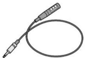
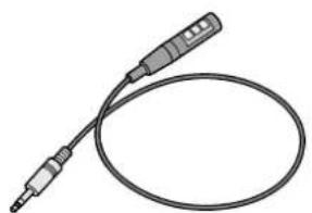
natural_image
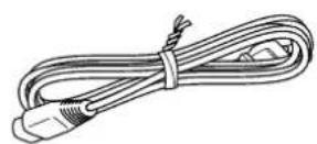
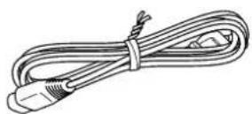
Illustration of a handheld electronic device with two leads and a coiled cable (no text or symbols)- Power cord ×1
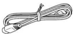
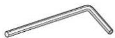
• Hexagonal wrench (2.5 mm) ×1
* To adjust the tonearm height
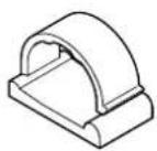
- Cable clamp × 1
* Use this clamp if you connect a phono cable directly to the tonearm.
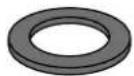
- Washer × 1
* For the head shell
• Owner's Manual (this book)
- Safety Brochure
- Supplement

CAUTION
Pay attention to these small accessory items to prevent children from swallowing them by accident.
Have the following items ready:
- Cartridge
• XLR balanced cable* For a balanced connection
• RCA stereo cable* For an unbalanced connection
Top panel
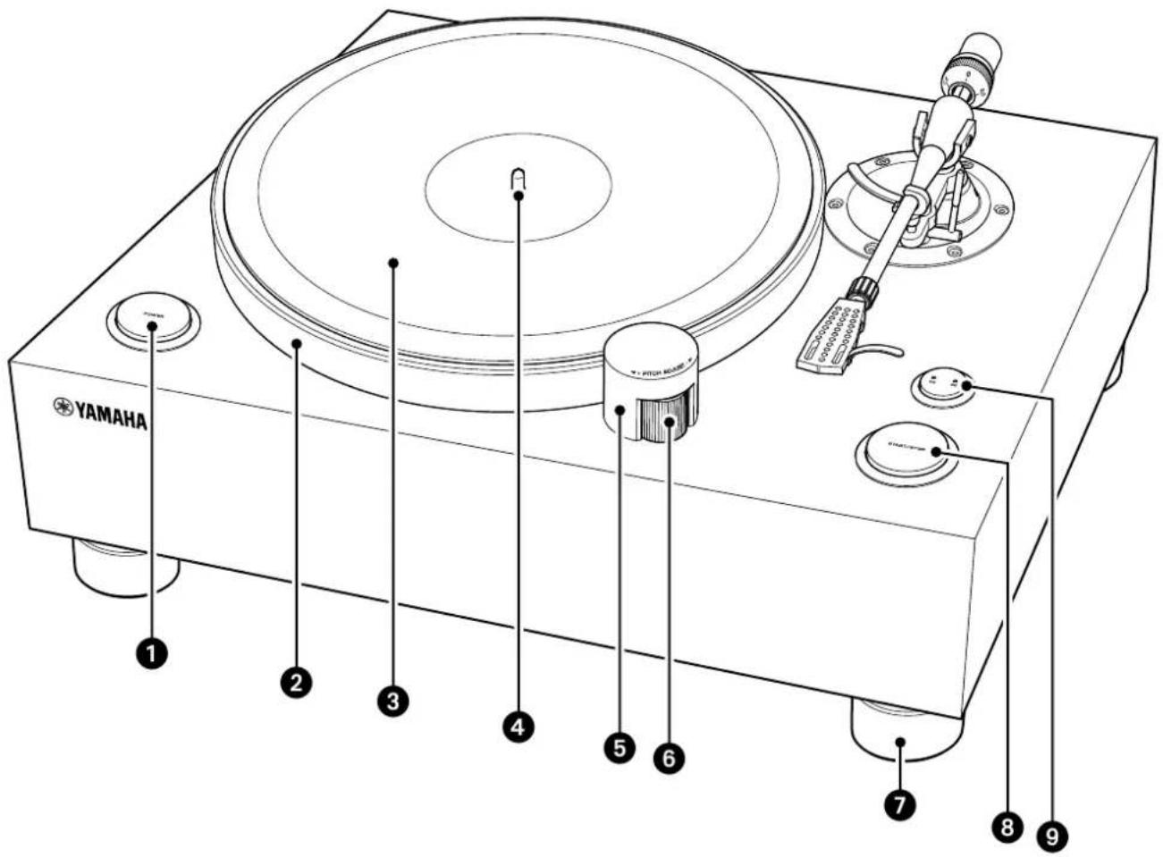
1 POWER button ( page 21)
② Platter ( page 15)
③ Turntable mat ( page 15)
4 Center spindle ( page 15)
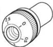
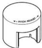
⑤ Dial cover ( page 15)
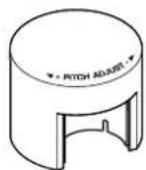
6 PITCH ADJUST (speed control)
(⇒ pages 15, 24)
⑦ Foot
8 START/STOP button (⇒ page 22)
9 Speed button ( page 22)
Speed indicator ( page 22)
Tonearm section
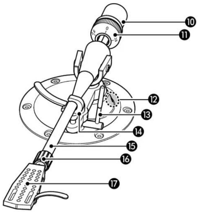
10 Counter weight ( page 15)
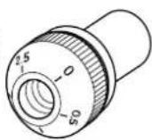
11 VTF* dial ( page 19)
* Vertical Tracking Force
⑫ VTA* adjustment screw (⇒ page 20)
* Vertical Tracking Angle
13 Lift lever ( page 22)
14 Arm rest ( page 19)
15 Tonearm ( page 15)
16 Lock nut ( page 16)
17 Head shell ( page 16)
Rear panel
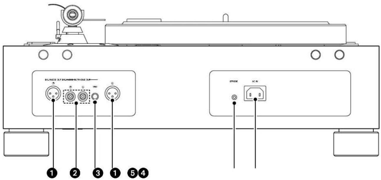
① BALANCED OUT jacks (⇒ page 17)
② PHONO OUT jacks (⇒ page 18)
③ GND (Ground) terminal ( page 18)
4 STROBE jack ( page 24)
⑤ AC IN inlet (⇒ pages 17, 18)
Getting ready
Location
Since a turntable and the sound of a record are easily affected by vibration, you should place the unit on a level surface that is extremely stable.
Place the turntable sufficiently far from your speaker system so that it will not be affected by sound pressure or vibration.

CAUTION
If you need to lift or relocate the unit, make sure that two or more people will do so.
NOTICE
Do not attempt to rotate the feet. Otherwise, they might be damaged.
■ Assembling the unit
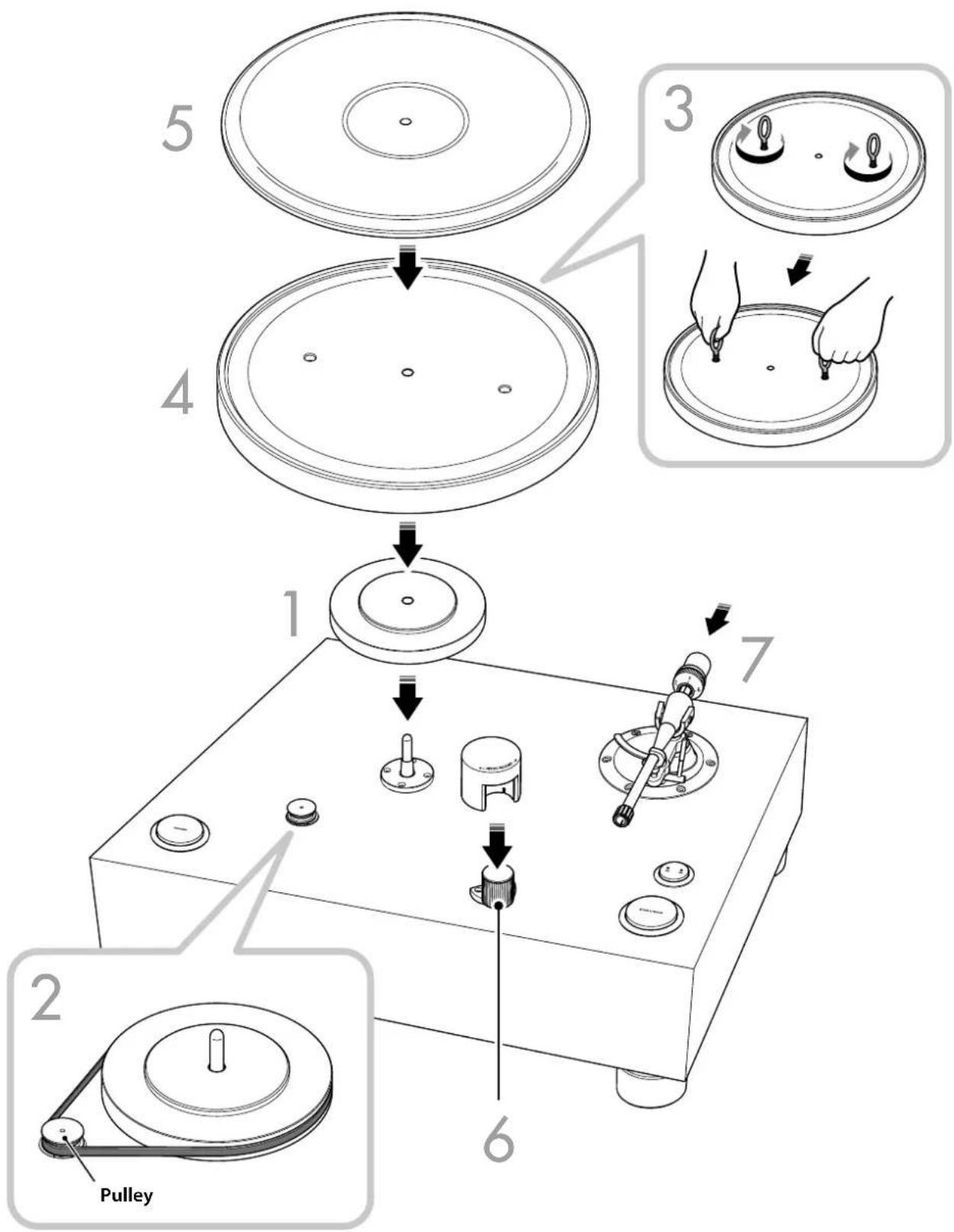
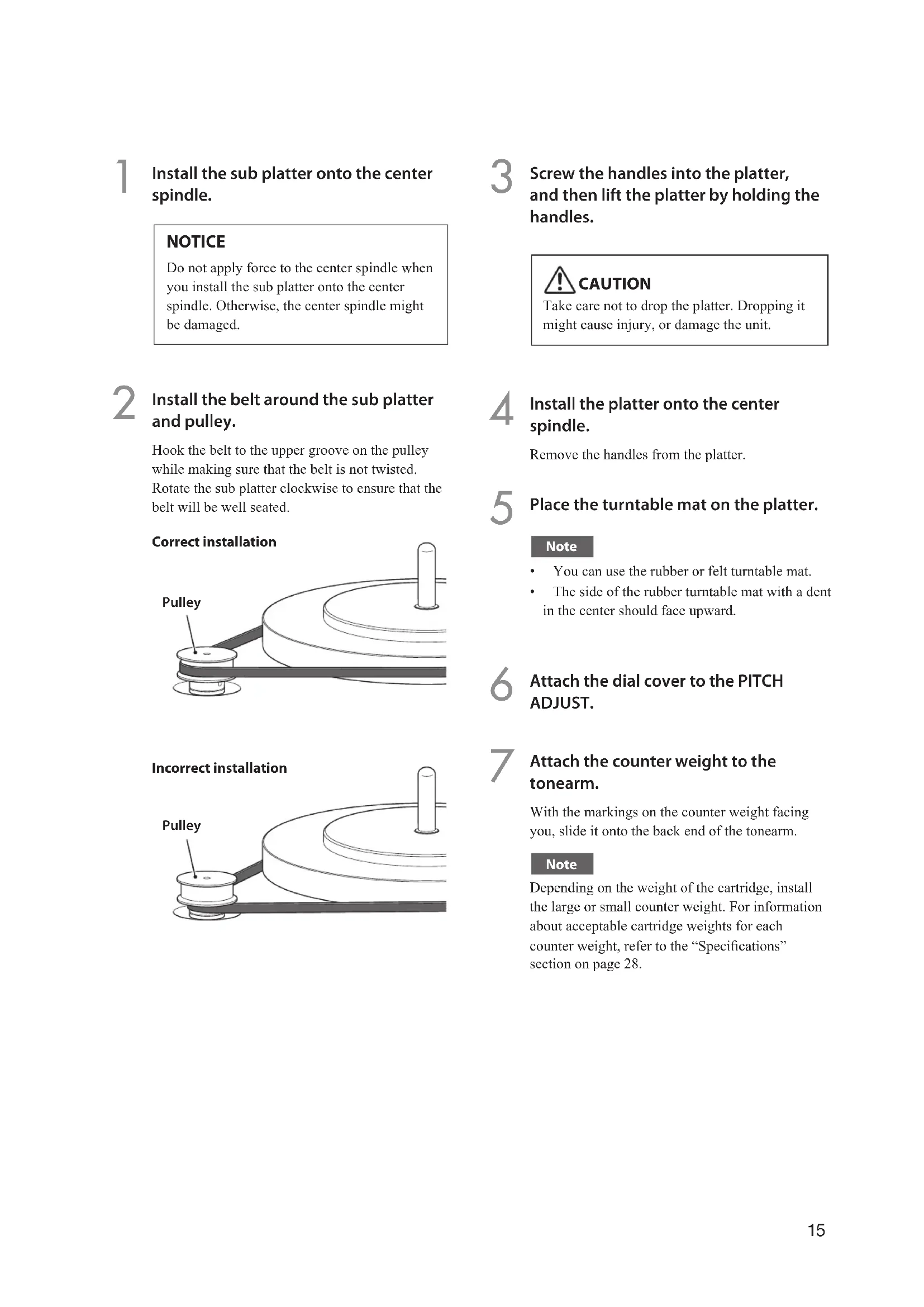
1 Install the sub platter onto the center spindle.
NOTICE
Do not apply force to the center spindle when you install the sub platter onto the center spindle. Otherwise, the center spindle might be damaged.
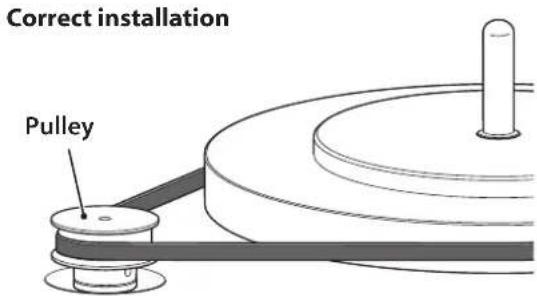
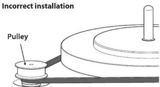
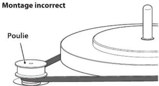
2 Install the belt around the sub platter and pulley.
Hook the belt to the upper groove on the pulley while making sure that the belt is not twisted. Rotate the sub platter clockwise to ensure that the belt will be well seated.
3 Screw the handles into the platter, and then lift the platter by holding the handles.

Take care not to drop the platter. Dropping it might cause injury, or damage the unit.
4 Install the platter onto the center spindle.
Remove the handles from the platter.
5 Place the turntable mat on the platter.
Note
• You can use the rubber or felt turntable mat.
- The side of the rubber turntable mat with a dent in the center should face upward.
6 Attach the dial cover to the PITCH ADJUST.
7 Attach the counter weight to the tonearm.
With the markings on the counter weight facing you, slide it onto the back end of the tonearm.
Note
Depending on the weight of the cartridge, install the large or small counter weight. For information about acceptable cartridge weights for each counter weight, refer to the “Specifications” section on page 28.
■ Installing a cartridge
A cartridge is not included with this product. Follow the steps below to install a commercially-available cartridge into the head shell.
Note
Refer to the instruction manual for the cartridge.
1 Connect the lead wires to the cartridge.
Lead wire Connector
| Red | → | R+ (red) |
| Green | → | R− (green) |
| White | → | L+ (white) |
| Blue | → | L− (blue) |
2 Provisionally secure the cartridge to the head shell.
3 Adjust the position of the cartridge.
Adjust the position of the cartridge and stylus as shown in the following illustration.
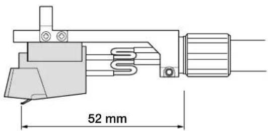
Note
The overhang of the tonearm on this unit is -17 mm.
4 Firmly secure the cartridge.
Verify that the side of the head shell is parallel with the cartridge, and then firmly tighten the screws.
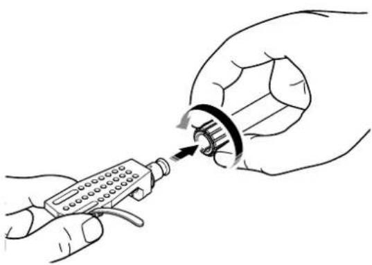
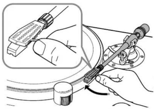
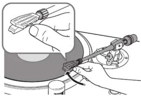
5 Attach the head shell to the tonearm.
Insert the head shell into the front end of the tonearm, and turn the lock nut to secure it.
natural_image
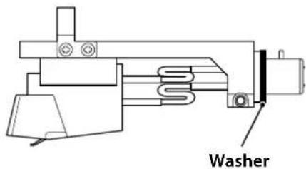
Illustration of hands using a handheld device to adjust a mechanical component (no text or symbols visible)Note
If you prefer, attach the washer to the head shell.
Making connections

CAUTION
Finish making all other connections before you connect the power cord to an AC outlet.
Note
- Do not use both balanced and unbalanced connections at the same time.
- For additional information, please refer to the owner's manuals for the device that you are connecting.
Balanced connection
Use an XLR balanced cable to connect your amplifier to the BALANCED OUT jacks.
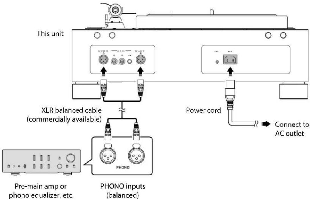
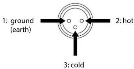
Note
- Connect the turntable to the XLR balanced input jacks on your amplifier. The pin assignments for these jacks are shown below.
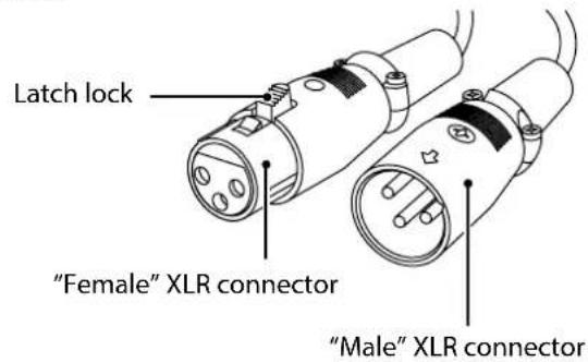
- When connecting, be sure to match the pins and insert the connector of the "female" XLR balanced cable. When disconnecting, pull out the "female" XLR balanced cable while pressing down the latch lock on the plug.
Unbalanced connection
Use an RCA stereo cable to connect the amplifier to the PHONO OUT jacks.
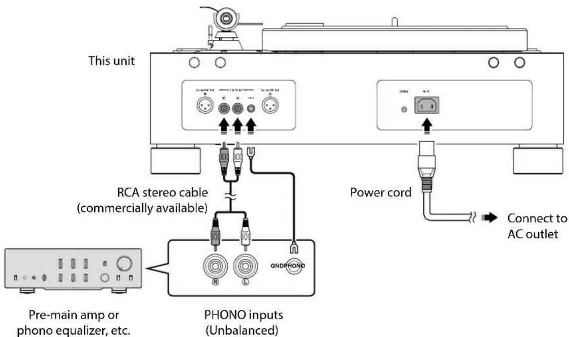
Note
The GND terminal is not a safety grounding (carthing) system.
Making adjustments
■ Adjusting the stylus pressure
Adjust the tonearm so that the appropriate stylus pressure will be applied to the record.
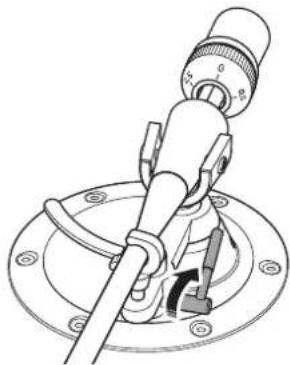
1 Remove the tonearm from the arm rest and move it slightly towards the record.
natural_image
Illustration of a hand using a tool to adjust cable or wire (no text or symbols visible)NOTICE
Take care that the stylus does not contact any part of the unit.
2 Turn the counter weight so that the tonearm will be horizontal.
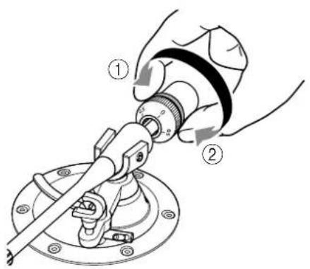
Toward①: Counter weight moves forward on the tonearm.
Toward②: Counter weight moves backward on the tonearm.
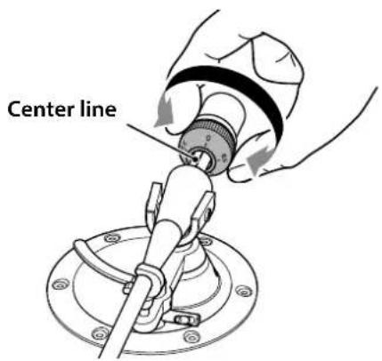
3 Return the tonearm to the arm rest.
4 Turn the VTF dial so that the "0" marking will be aligned with the center line on the back end of the tonearm.
Note
When turning the VTF dial, use your fingers to hold the counter weight in place so that it will not rotate.
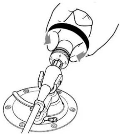
5 Turn the counter weight to set the VTF dial markings to the stylus pressure specified for the cartridge.
natural_image
Mechanical assembly diagram showing a hand operating a valve with rotating components (no text or symbols)Note
- Turning the counter weight also turns the VTF dial.
- Use a stylus pressure gauge to set an accurate stylus pressure.
■ Adjusting the tonearm height
If the tonearm and the record are not in parallel when you lower the stylus onto the record, you will need to adjust the tonearm height. Follow the steps below:
1 Return the tonearm to the arm rest and set it securely in position.
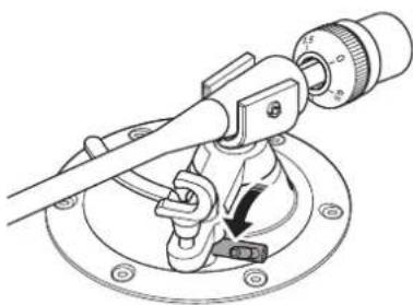
2 Use the hexagonal wrench to loosen the VTA adjustment screw.
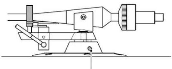
natural_image
Technical line drawing of a mechanical measuring instrument with no visible text or symbolsVTA adjustment screw
NOTICE
The tonearm is secured by the VTA adjustment screw. Before loosening the screw, gently support the entire tonearm with your hand so that it will not fall.
3 Move the tonearm up and down to adjust its height so that the tonearm and record will be in parallel.
4 Use the hexagonal wrench to tighten the VTA adjustment screw and secure the tonearm.
Turning the power on
Press the POWER button on the top panel of the unit to turn on the power to the unit.

natural_image
Line drawing of a handheld electronic device with a circular disc and control knob (no text or symbols)Playing a record
Starting the record

CAUTION
If you start to play a record without first sufficiently lowering the volume of your amplifier, a loud sound might occur when the tip of the stylus contacts the record. This could in some cases cause hearing loss and might damage your amplifier and speakers, so be sure to lower the volume of your amplifier first.
NOTICE
Be sure to use this product at an allowable operating temperature (10 °C–35 °C [50 °F–95 °F]). Otherwise, uneven rotation may occur, or the record or the tip of stylus may get damaged, in particular under cooler temperatures below 10 °C (50 °F).
This product is equipped with a relatively low-torque motor to achieve stable playback by suppressing torque fluctuation during rotation. If the grease viscosity of the center spindle increases and thickens under cooler temperatures, the rotational load of the turntable also increases, and may force the motor to exceed its performance limits. If this happens, the selected rotation speed may not be achieved or an uneven rotation may occur.
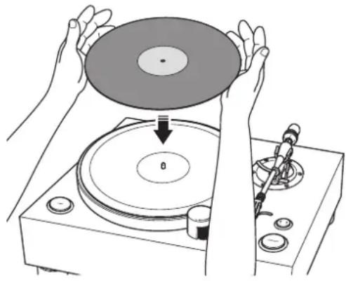
1 Place the record on the platter.
If you are playing a 45 rpm record, use the 45 rpm adaptor.
natural_image
Illustration of hands operating a CD to press or download a disc, with no visible text or symbols2 Press the speed button repeatedly to select the rotation speed that is appropriate for the record.
The speed indicator for the selected speed will light up.
3 Press the START/STOP button.
The platter starts to rotate.
The speed indicator will be flashing until the selected speed is reached.
4 Raise the lift lever.
natural_image
Technical line drawing of a mechanical clamp or lever assembly (no text or symbols)5 Move the tonearm to the playback position of the record.
natural_image
Illustration of hands using a tool to adjust or install a component, with no visible text or symbols.6 Lower the lift lever.
The tonearm is lowered, and the record begins to play.
natural_image
Technical line drawing of a mechanical clamp or caliper assembly with no visible text or symbols■ Pausing the record
If you raise the lift lever, the tonearm rise and playback pauses. When you lower the lift lever, playback resumes.
■ Stopping the record
1 Raise the lift lever.
2 Return the tonearm to the arm rest.
3 Lower the lift lever.
4 Press the START/STOP button.
The platter stops rotating.
Note
The tonearm does not automatically rise when the record finishes playing.
When necessary
Checking the speed
To check and adjust the speed, follow the steps below.
1 Connect the strobe light to the STROBE jack on the rear panel of the unit.
2 Place the stroboscopic disc on the platter.
3 Press the speed button repeatedly to select the rotation speed.
Press the START/STOP button.
The platter starts to rotate and the strobe light turns on.
5 Shine the strobe light onto the stroboscopic disc.
6 Use the PITCH ADJUST to adjust the speed.
Rotate the PITCH ADJUST in the + or - direction until the relevant herringbone ring on the stroboscopic disc appears to be stationary.
Note
- You can use the PITCH ADJUST to adjust the speed while the record is being played.
For adjustment steps and range, refer to the "Specifications" section on page 28. - The adjusted speed will be retained after the power to the unit is turned off.
- The stroboscopic disc and strobe light included in the package should be used only for this unit. When you check the speed, use both of them together.
Care
Caring for this unit
Wipe the unit with a soft dry cloth. If the finish of your unit is piano black, we recommend using a cleaning cloth made for pianos. Do not use chemicals such as benzine or thinner, since they might damage the surface.
Caring for the record stylus
The tip of the record stylus is extremely delicate. Handle it with care so that it is not damaged. If dust should adhere to the tip of the stylus, use a soft pointed brush to wipe it off starting at the base of the stylus and moving toward the tip, or use a commercially-available cleaner made for that purpose.
Note
Before you clean or perform maintenance on the unit or stylus, be sure to turn off the power to the unit.
Caring for records
Dirt adhering to a record can cause skips or noise. Use a commercially-available record cleaner to remove dirt.
Replacing the belt
In certain circumstances, the belt can wear out or break. If this occurs, replace the belt. For a replacement belt, contact your nearest authorized Yamaha dealer or service center.
Note
Before you replace the belt, turn off the power to the unit and connected devices, and disconnect the power cord of the unit from the AC outlet.
Troubleshooting
If the unit stops operating correctly, check the following points.
If taking the appropriate action does not solve the problem, or if you encounter a problem that is not listed below, press the POWER button located on the unit's top panel to turn off the power. Then disconnect the power cord and contact your nearest authorized Yamaha dealer or service center.
| Problem Cause Action | See page | ||
| Pressing the POWER button does not turn on the power. | The power plug has been unplugged from this unit's AC IN jack or from the AC outlet, or it is not firmly plugged in. | Firmly plug the power plug into this unit's AC IN jack and into an AC outlet. | 17 |
| The platter does not rotate. | The belt is not correctly positioned on the sub platter and pulley, or the belt has come off. | Attach the belt correctly to the sub platter and the pulley. | 15 |
| The POWER button is not on. Turn the POWER button on. 21 | |||
| No sound. | The head shell is not correctly attached to the tonearm. | Attach the head shell to the tonearm correctly. | 16 |
| The shell lead wires are not correctly connected to the cartridge. | Connect the shell lead wires to the cartridge correctly. | 16 | |
| The unit is not connected to the amplifier properly. | Connect the unit to the amplifier properly. | 17, 18 | |
| The mute setting of the amplifier is on. | Turn off the mute setting of the amplifier. | — | |
| Volume is too weak or too loud. | The cartridge setting of the amplifier or phono equalizer is incorrect. | Set the cartridge setting of the amplifier or phono equalizer correctly for the type of cartridge that you are using (MM or MC). | — |
| Something is wrong with the left/right sound balance. | The turntable is tilted. Place the turntable on a level surface. — | ||
| The pitch of the music being played sounds too high or too low. | The speed setting is incorrect. | Set the speed setting correctly. This unit does not support SP records (78 rpm). | 22 |
| Hum is audible. | The unit is not connected to the amplifier properly. | Connect the unit to the amplifier properly. | 17, 18 |
| The head shell is not firmly secured to the tonearm. | Use the lock nut to firmly secure the head shell to the tonearm. | 16 | |
| The cartridge is not correctly secured to the head shell. | Secure the cartridge to the head shell correctly. | 16 | |
| Skips occur. Noise occurs. The sound is distorted. | The stylus pressure is not adjusted correctly. | Adjust the stylus pressure properly. | 19 |
| The record is scratched or warped. | Do not use scratched or warped records. | — | |
| The record is dirty. | Use a commercially-available record cleaner to clean the record. | 24 | |
| The record is statically charged. | Use an anti-static brush to remove the static charge. | — | |
| The stylus is dirty. Remove the dirt from the stylus. | 24 | ||
| The stylus is worn down. Replace the stylus. — | |||
| The unit is placed in a location that is subject to vibration. | Place the unit on a level surface that is not subject to vibration. | — | |
| Feedback occurs. | The unit is too close to the speakers. | Locate the unit farther away from the speakers. | — |
| The sound volume is too high. | Adjust the volume of the amplifier. | — | |
Appendix
Specifications
Platter section
Phono motor section
Drive method .... Belt drive
Motor AC synchronous motor
Motor drive .... Crystal sinc wave
Rotation speed 33 1/3 rpm, 45 rpm
Rotation speed variation .... ±0.1%
Rotation speed adjustment
Built-in crystal osc./strobe light
Adjustment step 0.1%
Adjustment range .... ±1.5%
Wow and flutter 0.04% or less (W.R.M.S.)
Platter …… Aluminium
Diameter 350 mm
Sub platter Brass
Diameter 143 mm
Tonearm section
Type .... Static balance straight tonearm
Effective arm length 223 mm
Overhang -17 mm
Acceptable cartridge weight (including head shell) 16–23.5 g
(Counter weight: small) 23–34 g
(Counter weight: large)
Head shell weight 14 g
(including wires)
Audio section
Output jack
Analog audio ..... PHONO OUT (RCA) × 1
PHONO OUT (XLR) × 1
General
Power supply
[Models for U.S.A. and Canada] AC 120 V, 60 Hz
[Model for China] ..... AC 220 V, 50 Hz
[Model for Korea] ..... AC 220 V, 60 Hz
[Model for Australia] ..... AC 240 V, 50 Hz
[Models for U.K. and Europe].. AC 230 V, 50 Hz
[Model for Asia] ..... AC 220–240 V, 50/60 Hz
[Models for Central and South America, and Taiwan] ..... AC 110 V, 60 Hz
Power consumption
While playing 15 W
While stopped 0.4 W
Weight 26.8 kg
Dimensions (W × H × D) .... 546 × 223 × 411 mm (including feet and protrusions)
Allowable operating temperature ..... 10–35 °C
- The values listed above were measured at an ambient temperature of 20 °C.
- The contents of this manual apply to the latest specifications as of the publishing date. To obtain the latest manual, access the Yamaha website then download the manual file.
natural_image
Simple line drawing of a circular object with three small dots on its surface (no text or symbols)natural_image
Two overlapping circular objects with concentric rings and a central dot (no text or symbols)• Courroie ×1 • Contrepoids ×2

natural_image
Abstract curved line drawing with no text or symbols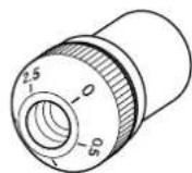

Grand
- Porte-cellule ×1
natural_image
Line drawing of a handheld electrical connector with ports and buttons (no text or symbols)natural_image
Circular diagram with concentric rings and a central dot, no text or symbols present- Stroboscope × 1
natural_image
Illustration of a handheld electronic device with two leads and a coiled cable (no text or symbols)10 Contrepoids ( page 39)
11 Bague de VTF* (⇒ page 43)
* Vertical Tracking Force (force d'appui vertical)
natural_image
Illustration of hands using a handheld device to adjust a mechanical component (no text or symbols visible)Note
natural_image
Illustration of hands using a tool to adjust cable or wire components, showing a magnified inset of the connector (no text or symbols present)AVIS
natural_image
Mechanical assembly diagram showing a hand operating a valve with rotating components (no text or symbols)Note
natural_image
Line drawing of a handheld electronic device with a circular disc and control knob (no text or symbols)Lecture d'un disque
natural_image
Illustration of hands operating a CD to press or download a disc, with no visible text or symbolsnatural_image
Technical line drawing of a mechanical device with a lever and adjustment knob (no text or symbols)natural_image
Illustration of hands using a mechanical tool to adjust or install a component, with no visible text or symbols.natural_image
Technical line drawing of a mechanical tool with a dial and base mount (no text or symbols)(Contrepoids: petit)
23-34 g
(Contrepoids: grand)
natural_image
Simple line drawing of a circular object with three small dots on its surface (no text or symbols)- Unterteller × 1
natural_image
Two overlapping circular objects with concentric rings and a central dot (no text or symbols)natural_image
Abstract curved line drawing with no text or symbols

Groß
Klein
natural_image
Line drawing of a handheld electrical connector with buttons and handle (no text or symbols)natural_image
Circular object with concentric rings and a central dot, no visible text or symbols- Stroboskop × 1

natural_image
Illustration of a handheld electronic device with two leads and a coiled cable (no text or symbols)- Netzkabel × 1
natural_image
Illustration of hands using a handheld device to adjust a mechanical component (no text or symbols visible)Hinweis
natural_image
Illustration of a hand using a tool to adjust cable or wire, showing a magnified inset of the connector (no text or symbols present)ACHTUNG
natural_image
Mechanical assembly diagram showing a hand operating a valve with rotating components (no text or symbols)Hinweis
natural_image
Technical line drawing of a mechanical measuring instrument with no visible text or symbolsnatural_image
Line drawing of a handheld electronic device with a circular disc and control knob (no text or symbols)natural_image
Illustration of hands operating a CD to press a disc, with no visible text or symbolsnatural_image
Technical line drawing of a mechanical device with a lever and adjustment knob (no text or symbols)natural_image
Illustration of hands using a tool to adjust or install a mechanical component, no text or symbols visiblenatural_image
Technical line drawing of a mechanical clamp or dial assembly (no text or symbols)natural_image
Simple line drawing of a circular object with three small dots on its surface (no text or symbols)- Undertallrik ×1
natural_image
Two overlapping circular objects with concentric rings and a central dot (no text or symbols)- Rem ×1 • Motvikt ×2

natural_image
Abstract curved line drawing with no text or symbols

Stor
- Huvudskal ×1
natural_image
Line drawing of a handheld electrical connector with ports and buttons (no text or symbols)- 45 rpm adapter ×1
- Rattskydd ×1
- Handtag ×2

natural_image
Circular diagram with concentric rings and a central dot, no text or symbols present- Strobbelysning × 1

natural_image
Line drawing of a handheld electronic device with two leads (no text or symbols)- Strömsladd ×1

- Sexkantig skiftnyckel (2,5 mm) ×1
10 Motvikt (⇒ sidan 87)
11 VTF* ratt (⇒ sidan 91)
* Vertical Tracking Force (Vertical spårningskraft)
⑫ VTA* justerskruv (⇒ sidan 92)
* Vertical Tracking Angle (Vertical spårningsvinkel)
① BALANCED OUT-uttag (⇒ sidan 89)
② PHONO OUT-uttag (⇒ sidan 90)
③ GND (Jordad) kontakt (⇒ sidan 90)
4 STROBE-uttag ( sidan 96)
5 AC IN-ingång (⇒ sidor 89, 90)
Komma igång
Plats
natural_image
Illustration of hands using a handheld device to adjust a circular component (no text or symbols visible)Obs!
natural_image
Illustration of hands using a compass to adjust cable or wire (no text or symbols present)MEDDELANDE
natural_image
Diagram of a hand using a mechanical lever to adjust a valve, showing motion arrows (no text or symbols)Obs!
natural_image
Line drawing of a handheld electronic device with a circular disc and control knob (no text or symbols)Spela en post
Starta skivan

FÖRSIKTIGHET
natural_image
Illustration of hands operating a CD to press a disc, with a tool inserted (no text or symbols visible)2
natural_image
Technical line drawing of a mechanical device with a lever and adjustment knob (no text or symbols)natural_image
Illustration of hands using a tool to adjust or install a mechanical component, no text or symbols present6 Sänk spaken.
natural_image
Technical line drawing of a mechanical tool with a dial and base plate (no text or symbols)■ Pausa skivan
Rotationshastighet.... 33 1/3 rpm, 45 rpm
natural_image
Simple line drawing of a circular object with three small dots on its surface (no text or symbols)- Sottopiatto ×1

- Tappetino ×2
natural_image
Two overlapping circular objects with concentric rings and a central dot (no text or symbols)• Cinghia ×1 • Contrappeso ×2
natural_image
Abstract curved line drawing with no text or symbols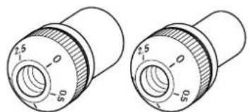
natural_image
Technical line drawing of two cylindrical mechanical components with no visible text or symbolsGrande
Piccolo
- Portatestina × 1
natural_image
Line drawing of a handheld device with ports and a handle (no text or symbols)natural_image
Circular object with concentric rings and a central dot, no visible text or symbols- Luce strobo ×1

natural_image
Illustration of a medical or laboratory probe with a coiled cable and two connectors (no text or symbols)① Prese BALANCED OUT (⇒ pagina 113)
② Prese PHONO OUT (⇒ pagina 114)
③ Terminale GND (terra) (⇒ pagina 114)
4 Presa STROBE (⇒ pagina 120)
5 Presa AC IN (⇒ pagine 113, 114)
Preparazione
Posizione
natural_image
Illustration of hands using a handheld device to adjust or install a mechanical component (no text or symbols visible)Nota
natural_image
Illustration of hands using a tool to adjust cable or wire, showing a magnified view of the connector (no text or symbols present)AVVISO
natural_image
Diagram of a hand using a mechanical lever to adjust a valve, showing motion arrows (no text or symbols)Nota
natural_image
Line drawing of a handheld electronic device with a circular disc and control knob (no text or symbols)natural_image
Illustration of hands operating a CD to press a disc, with a tool inserted (no text or symbols visible)natural_image
Technical line drawing of a mechanical clamp or lever assembly (no text or symbols)natural_image
Illustration of hands using a tool to adjust or install a mechanical component, with no visible text or symbols.natural_image
Technical line drawing of a mechanical tool with a circular base and adjustment knob (no text or symbols)Dimensioni (L × A × P) ..... 546 × 223 × 411 mm
natural_image
Simple line drawing of a circular object with three small dots on its surface (no text or symbols)- Subplato × 1

- Tapete de giradiscos ×2
natural_image
Two overlapping circular objects with concentric rings and a small dot, no text or symbols present.- Correa ×1 • Contrapeso ×2
natural_image
Abstract curved line drawing with no text or symbols

Grande
Pequeño
• Cabezal de la aguja ×1
natural_image
Line drawing of a handheld electrical connector with ports and buttons (no text or symbols)natural_image
Circular object with concentric rings and a central dot, no visible text or symbols- Luz estroboscópica ×1
natural_image
Line drawing of a handheld electronic device with two leads (no text or symbols)natural_image
Illustration of hands using a handheld device to adjust a mechanical component (no text or symbols visible)Nota
natural_image
Illustration of a hand using a tool to adjust cable or wire, showing a magnified inset of the connector (no text or symbols present)AVISO
natural_image
Mechanical assembly diagram showing a hand operating a valve with rotating components (no text or symbols)Nota
natural_image
Line drawing of a handheld electronic device with a circular disc and control knob (no text or symbols)natural_image
Illustration of hands operating a CD to press a disc, with a tool inserted (no text or symbols visible)natural_image
Technical line drawing of a mechanical clamp or lever assembly (no text or symbols)natural_image
Illustration of hands using a tool to adjust or install a mechanical component, no text or symbols visiblenatural_image
Technical line drawing of a mechanical clamp or caliper assembly with no visible text or symbols■ Pausa del disco
Gereedmaken .....157
Locatie . . . . . . . . . . . . . . . . . 157
Montage 158
natural_image
Simple line drawing of a circular object with three small dots on its surface (no text or symbols)natural_image
Two overlapping circular objects with concentric rings and a central dot (no text or symbols)• Snaar ×1 • Contragewicht ×2


Groot
Klein
- Elementkop ×1

natural_image
Line drawing of a handheld electrical connector with ports and buttons (no text or symbols)- 45-toerenadapter ×1

- Schijfdop ×1
- Oog ×2
natural_image
Circular diagram with concentric rings and a central dot, no text or symbols present- Stroboscooplamp × 1
natural_image
Line drawing of a handheld electronic device with two leads (no text or symbols)- Netsnoer × 1
10 Contragewicht ( pagina 159)
11 VTF* schijf (⇒ pagina 163)
* Vertical Tracking Force (Verticale volgkracht)
⑫ VTA* stelschroef (⇒ pagina 164)
* Vertical Tracking Angle (Verticale volghoek)
13 Armlifthendel ( pagina 166)
14 Armsteun (⇒ pagina 163)
15 Draaitafelarm (⇒ pagina 159)
16 Borgmoer (⇒ pagina 160)
17 Elementkop ( pagina 160)
Achterpaneel

natural_image
Illustration of hands using a handheld tool to adjust a mechanical component (no text or symbols visible)Opmerking
natural_image
Illustration of a hand using a tool to adjust cable or wire, showing a magnified inset of the connector (no text or symbols present)LET OP
natural_image
Mechanical assembly diagram showing a hand operating a valve with rotating components (no text or symbols)Opmerking
natural_image
Line drawing of a handheld electronic device with a circular disc and control knob (no text or symbols)natural_image
Illustration of hands operating a CD to press a disc, with no visible text or symbolsnatural_image
Technical line drawing of a mechanical device with a lever and adjustment knob (no text or symbols)natural_image
Illustration of hands using a tool to adjust or install a component, no text or symbols visible6 Breng de armlifthendel omlaag.
natural_image
Technical line drawing of a mechanical clamp or tool assembly (no text or symbols present)Toerental 33 1/3 rpm, 45 rpm
Toerentalvariatic ±0,1%
Toerentalaanpassing
natural_image
Simple line drawing of a circular object with three small dots on its surface (no text or symbols)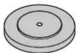
natural_image
Two overlapping circular objects with concentric rings and a small dot, no text or symbols present.natural_image
Line drawing of a handheld electrical connector with ports and clamps (no text or symbols)natural_image
Circular diagram with concentric rings and a central dot, no text or symbols presentnatural_image
Illustration of a medical or laboratory probe with a coiled cable and two connectors (no text or symbols)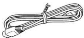
natural_image
Illustration of hands using a handheld device to adjust or install a mechanical component (no text or symbols visible)Примечание
natural_image
Illustration of hands using a tool to adjust cable or wire, showing a magnified inset of the connector (no text or symbols present)УВЕДОМЛЕНИЕ
natural_image
Mechanical assembly diagram showing a hand operating a valve with rotating components (no text or symbols)Примечание
natural_image
Technical line drawing of a mechanical instrument with no visible text or symbolsnatural_image
Line drawing of a hand operating a CD or DVD disc with a rotary knob and adjustment knobs (no text or symbols)natural_image
Illustration of hands operating a CD or DVD disc with a tool inserted, no text or symbols presentnatural_image
Technical line drawing of a mechanical clamp or lever assembly (no text or symbols)natural_image
Illustration of hands using a tool to adjust or install a component, with no visible text or symbols.natural_image
Technical line drawing of a mechanical clamp or caliper assembly with no visible text or symbols...... PHONO OUT (RCA) × 1
PHONO OUT (XLR) × 1
https://download.yamaha.com/