
DCS6517 - Surveillance Camera D-LINK - Free user manual and instructions
Find the device manual for free DCS6517 D-LINK in PDF.
User questions about DCS6517 D-LINK
0 question about this device. Answer the ones you know or ask your own.
Ask a new question about this device
Download the instructions for your Surveillance Camera in PDF format for free! Find your manual DCS6517 - D-LINK and take your electronic device back in hand. On this page are published all the documents necessary for the use of your device. DCS6517 by D-LINK.
USER MANUAL DCS6517 D-LINK
Quick Installation Guide
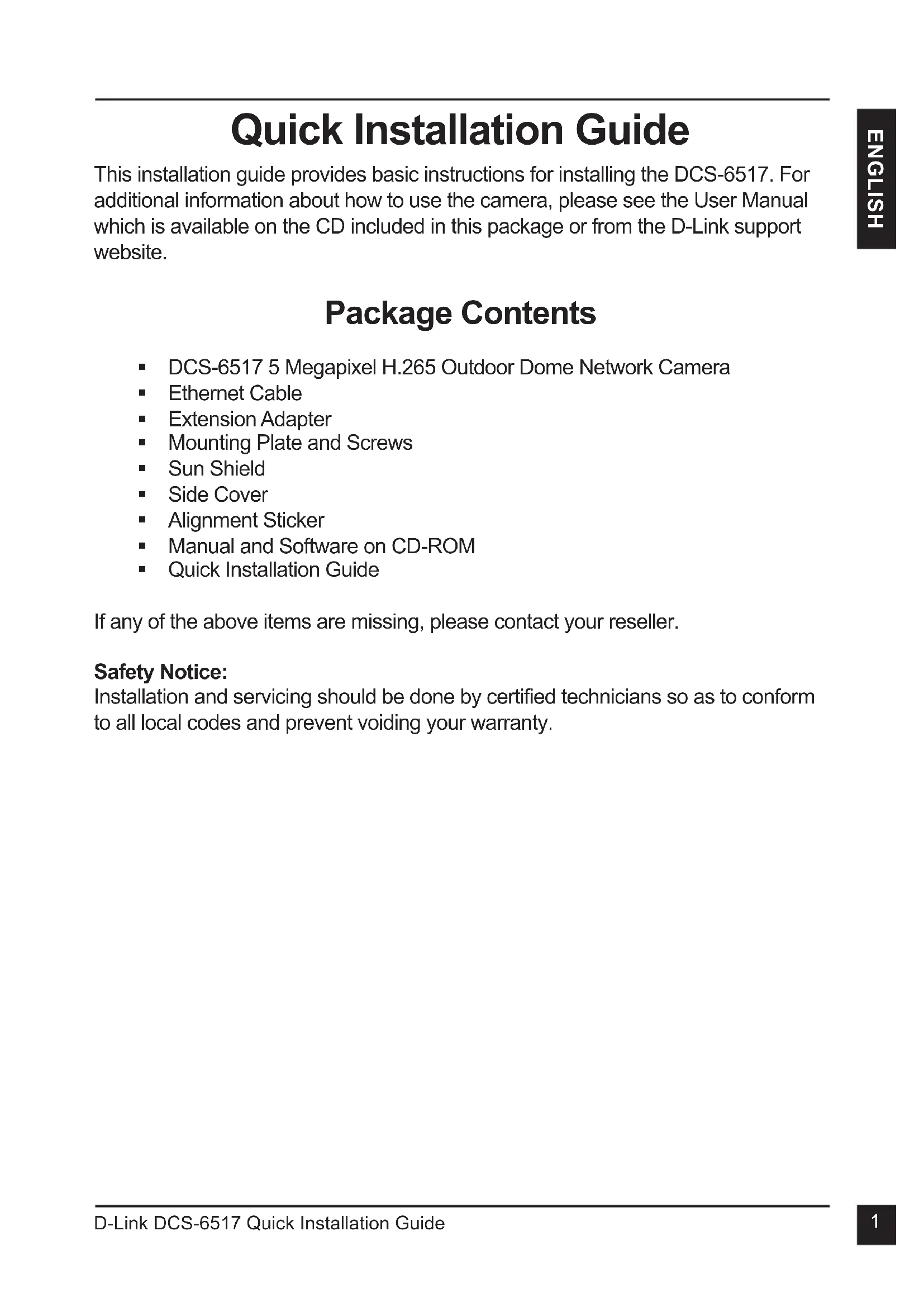
5 Megapixel H.265 Outdoor Dome Network Camera
This document will guide you through the basic installation process for your new D-Link Network Camera.
DCS-6517
Quick Installation Guide
KpaTKoe pyKOBOCTBO NO yCTaHOBKe
Documentation also available on
CD and via the D-Link Website
Quick Installation Guide
This installation guide provides basic instructions for installing the DCS-6517. For additional information about how to use the camera, please see the User Manual which is available on the CD included in this package or from the D-Link support website.
Package Contents
DCS-6517 5 Megapixel H.265 Outdoor Dome Network Camera
- Ethernet Cable
- Extension Adapter
- Mounting Plate and Screws
Sun Shield
Side Cover
- Alignment Sticker
- Manual and Software on CD-ROM
Quick Installation Guide
If any of the above items are missing, please contact your reseller.
Safety Notice:
Installation and servicing should be done by certified technicians so as to conform to all local codes and prevent voiding your warranty.
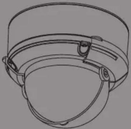
Hardware Overview
| 1 IR | LEDs | Provide illumination for low-light environments. | |
| 2 Tilt Lock Screw | Can be loosened to adjust the camera's tilt angle. | ||
| 3 Camera Lens | Camera lens to record video of the surrounding area. | ||
| 4 Power/Status LED | Indicates the camera's current status. | ||
| 5 Light Sensor | Measures lighting conditions and switches between day and night mode accordingly. | ||
| 6 Horizontal Lock Screw | Can be loosened to adjust the horizontal rotation of the camera. | ||
| 7 microSD Card Slot | Accepts a microSD card for onboard storage of snapshots and video. | ||
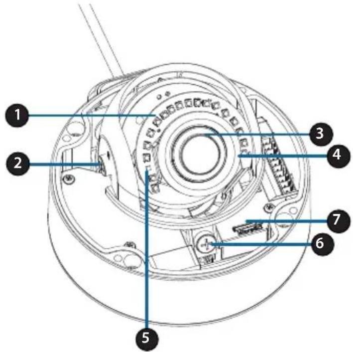
| 8 Ethernet Jack | Connects to an RJ45 Ethernet port. Can be used with PoE to provide power to the camera. | ||
| 9 Cable Channels | Allow cables to exit the camera from the back or side. | ||
| 10 Cable Harness Port | Connects to the optional cable harness (not included). | ||
| 1. 12V IN | 6. 12V OUT | ||
| 2. GND | 7. GND | ||
| 3. AUD IN | 8. RESET | ||
| 4. AUD GND | 9. DI | ||
| 5. AUD OUT | 10. DO | ||
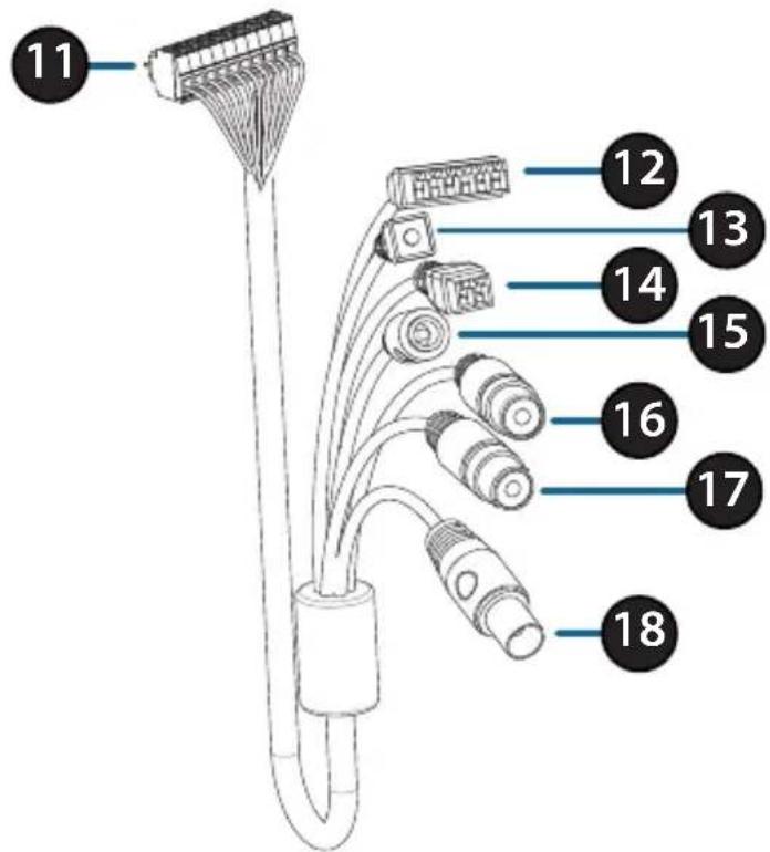
Optional Cable Harness (not included)
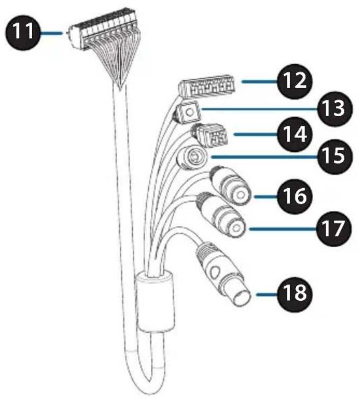
| 11 | Cable Harness Connector | Connects to the DCS-6517. For more details on connecting the A/V cable, refer to the User Manual. |
| 12 | DI/DO Connector | I/O connectors for external devices. (12 V DC output not supported for the DCS-6517) |
| 13 | Reset Button | Press and hold the button for 10 seconds to reset the camera back to the factory default settings. |
| 14 | 24V Power Connector | Not supported for the DCS-6517. |
| 15 | Power Connector | Power connector for a 12 V DC power adapter (not included). |
| 16 | Audio Out (Green) | Connects to a speaker. |
| 17 | Audio In (Red) | Connects to a microphone. |
| 18 | BNC Connector | Not supported for the DCS-6517. |
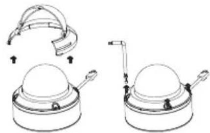
Connecting the Optional Cable Harness
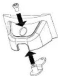
Remove the sun shield by lifting it off of the camera. Use the included security wrench to remove the 4 screws from the top of the camera, then remove the camera cover.
Remove a waterproofing plug from the side or bottom of the camera depending on how you want the cables to exit the camera.
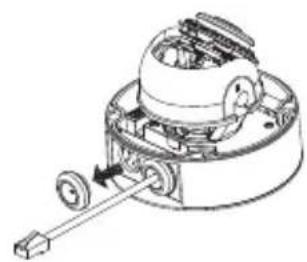
Push the camera connector and cable through the hole, and insert the cable's waterproofing plug.
Make sure the plug is inserted properly to ensure a good seal.
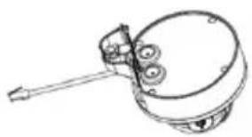
For side cable exit:
Attach the side cover via the provided screws.
Slide the cover over the cable ports.
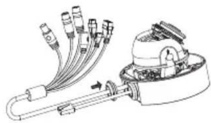
For bottom cable exit:
Attach the protective side cover via the provided screws.
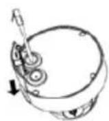
Connect the camera connector to the camera.
Reattach the camera cover using the security wrench to tighten the 3 screws, and reattach the sun shield.
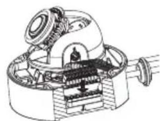
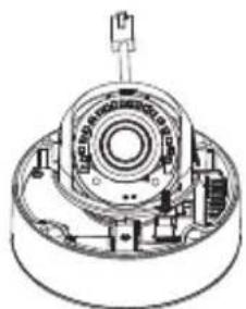
microSD Card Installation
Remove the sun shield by lifting it off of the camera. Use the included security wrench to remove the 4 screws from the top of the camera, then remove the camera cover.

Insert the microSD card with the gold contacts facing the outside of the camera. To eject the microSD card, push the card into the slot.
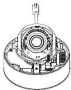
Reattach the camera cover using the security wrench to tighten the 4 screws, and reattach the sun shield.
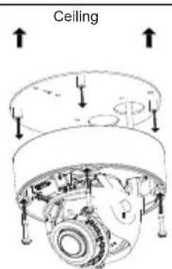
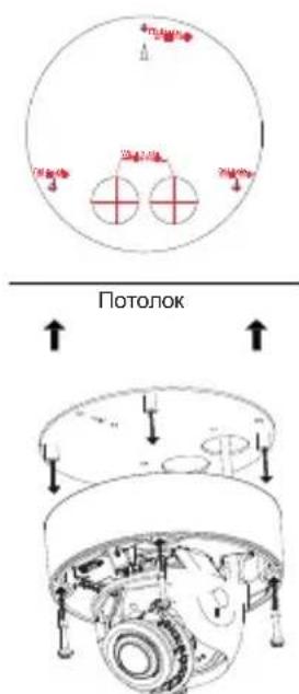
Mounting the Camera on the Ceiling
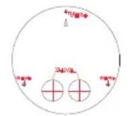
Locate a suitable position on the ceiling that is capable of supporting the weight of the camera. Attach the alignment sticker to the ceiling or wall.
Align the mounting plate to the drilled holes in the ceiling surface then tighten the screws.
Align the camera to the mounting plate and screw the camera body to the plate tightly.
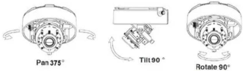
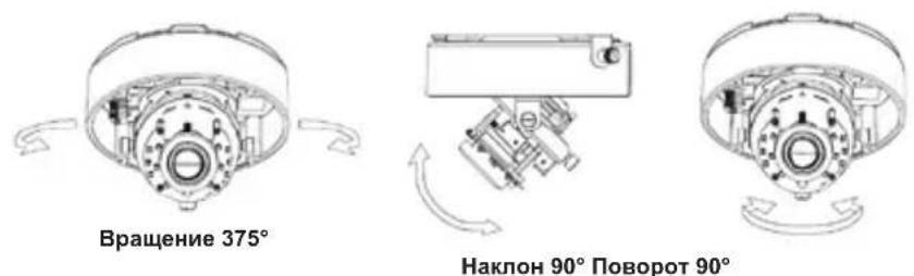
Adjusting the Camera's Lens
Adjust the Camera's Lens gimbal; Turn the lens module left and right, up and down and the orientation until the desired position is achieved. Tighten the pan, tile and the adjustment screw once completed.
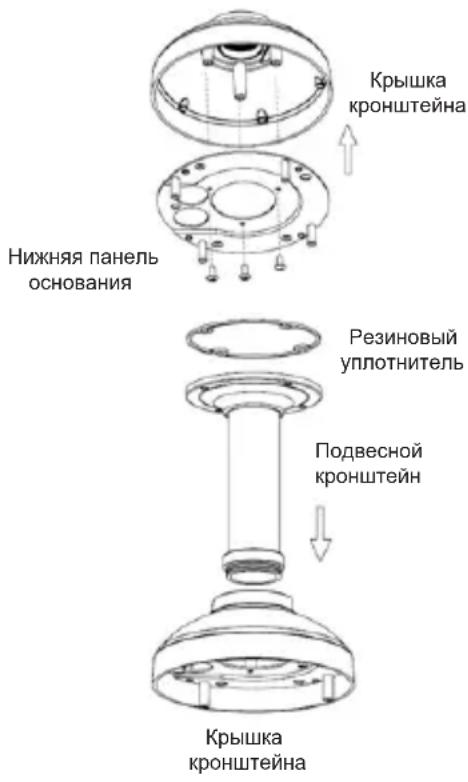
Installing the Pendant Mount (Optional)
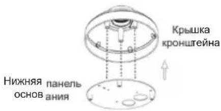
Attach the mounting plate to the bracket cap using the three included screws.
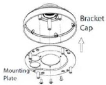
Locate a suitable position on the ceiling for a 34mm (+2 / - 0mm) hole to be cut. Use the included template to mark and cut the mounting holes.
Locate a suitable position on the ceiling for a 34mm (+2 / - 0mm) hole to be cut. Use the included template to mark and cut the wiring hole.
Drill four 6 mm holes corresponding to the holes in the mounting template and insert the plastic anchors into these holes.
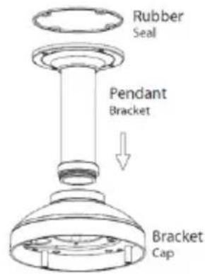
Place the rubber seal between the pendant bracket and the ceiling to ensure a waterproof seal between the ceiling and the bracket.
Attach the pendant bracket to the ceiling using the screws provided.
Attach the bracket cap to the bottom of the pendant bracket by rotating the cap counterclockwise to tighten it into place.
Insert the screw into the base of the pendant bracket at the top of the bracket cap to secure the bracket cap into place.
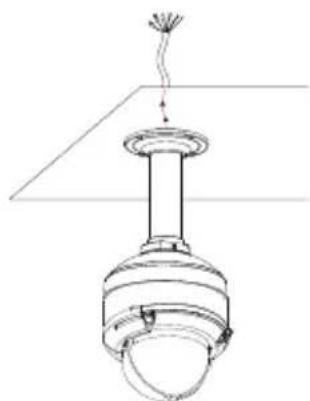
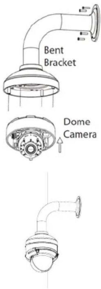
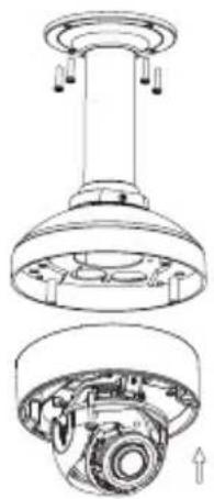
Thread an Ethernet cable and the power cable through the pendant bracket.

Place the camera body onto the bracket cap and attach the dome to the base of the camera using the four long screws and the security screw.
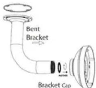
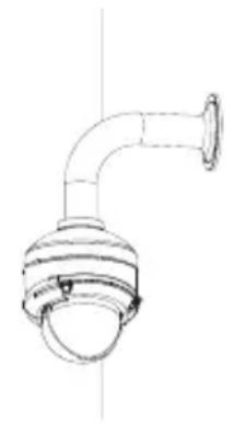
Installing the Right-Angle Mount (Optional)
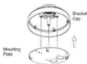
Attach the mounting plate to the bracket cap using the included three screws.
Locate a suitable position on the ceiling for a 34mm (+2 / - 0mm) hole to be cut. Use the included template to mark and cut the mounting holes.
Drill four 6mm holes corresponding to the holes in the mounting template and insert the plastic anchors into these holes.
Place the rubber seal between the right-angle bracket and the ceiling to ensure a waterproof seal between the ceiling and the bracket.
Attach the right-angle bracket to the ceiling using the screws provided.
Attach the bracket cap to the bottom of the right-angle bracket by rotating the cap counterclockwise to tighten it into place.
Insert the screw into the base of the right-angle bracket at the top of the bracket cap to secure the bracket cap into place.
Thread an Ethernet cable and the power cable through the pendant bracket.
Place the camera body onto the bracket cap and attach the dome to the base of the camera using the three long screws and the security screw.
Connecting the Camera
Connection with a PoE Switch
- Connect the Ethernet cable to your PoE switch or injector. The Ethernet cable will provide the camera with both power and a network connection.

If you have the optional cable harness, you can also use the following connection method:
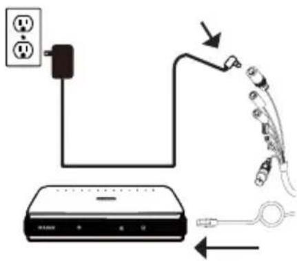
General Connection Using 12 V DC Power Adapter (not included)
- Connect the Ethernet cable to your network.
- Connect your power adapter to the camera's power connector, then plug in the power adapter.
Configuring the Camera
Insert the DCS-6517 CD into your computer's CD-ROM drive to begin the installation. If the Autorun function on your computer is disabled, or if the D-Link Launcher fails to start automatically, run D:\autorun.exe, where D: represents the drive letter of your CD-ROM drive.
Viewing Your Camera via a Web Browser
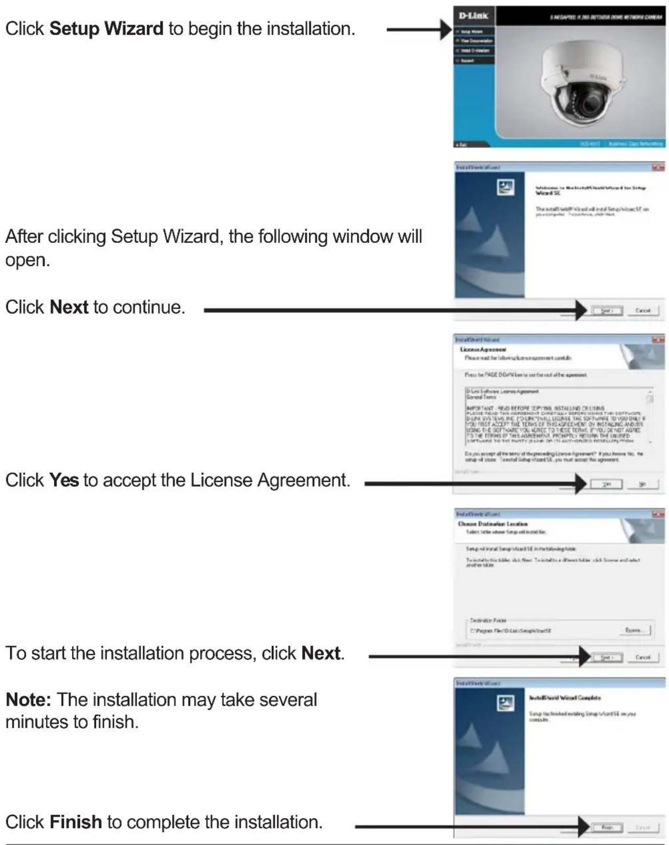
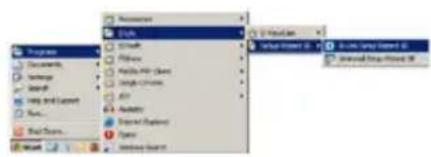
Click on the D-Link Setup Wizard SE icon that was created in your Windows Start menu (Start > D-Link > Setup Wizard SE).
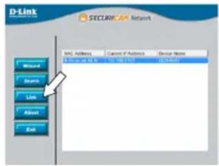
Select the camera and click Link to access the web configuration.
The Setup Wizard will automatically open your web browser to the IP address of the camera.
The first time you connect to the camera, you will be asked to set a password for the administrator account. After entering a password, click Save.
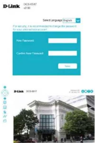
The camera's live video page will open, and you can now control and configure your camera. For additional information about web configuration, please refer to the user manual, which is available on the D-Link website.
Additional Information
Additional help and product information is available online at http://www.dlink.com/
Warranty Information
Please visit http://warranty.dlink.com/ for warranty information for your region.
KpaTkoe pykoBODCTBO NO yCTaHOBKe
PnKpeNte KynoJ KaMepbl, 3aTayB KInOyOM 4 BnHTa, N yCTaHOBITE COJIHcE3aUHTbI K03bIpeK.
YctaHOBka KapTbI microSD
CHIMITE c KaMepbl COHcE3aUHTbI K03bIpeK, NOHRA ERO BBepx. IcNoJIb3yIte BXOJaIIN B KOMJIeKT NocTaBKn KJIIOU, YTO6bl BbIKpyTITb 4 BNHTa CBepxY KaMepbl, a 3aTeM CHIMITE KJNOI KaMepbl.

YcTaHOBnTe KapTy microSD B cNt KOHTaKtAmn BHN3.
UTo6bl n3Bnueb ycTaHOBnEHHyO B cNt KapTy microSD,
HaKMnTe Ha Hee.
PnKpeNte KynoJ KaMepbI, 3aTaNyB KInOyOM 4 BnHTa, N yCTaHOBNTe COHnce3aUHTbI K03bIpeK.
YcTaHOBka KaMepbI Ha NOTOJIke
Bb6epTe PoxoJee MeTo Ha NotOKe, Cnoc6Hoe BldepKaTb Bec KaMepbl. PnKpeNtHe HnpaBnIounn CTKeP K NOTOky I npocBepJIte OTBepCTnB MeCTax, OTMeueHHbIX Ha CTKepe. BcTaBbTe aHKepbB IV npocBepJeHHbIe OTBepCTnR.
CoBmecTte HxHIOI NaHeJIb OCHOBaHnKaMepbl C npocBepJIeHHbIMN OTBepCTnAMn Ha NOTOLke N BCTaBBTe BNHTbl B aHKepbI. BkpyTte BnHTbl OTBepTKoI.
CoBmecTnte kamepy c ee HnXHei nHaHeIbIO nHaJeKHO npIKpyTnte BnHTamn kamepy K 3ToI nAHeJI.
PergunpoBka obBeKTHBa kamepbI
Otperynpyte noIoxeHne obekTbA kamepbI NO TpeM OcM. NobopaunBaTe obekTNB BHeBO N BnpaBO, BBepx N BHN3, YTO6bl yCTaHOBTb erO B Tpe6yemOM noIoxeHn. 3akpenTe BNtbl COOTBETCTByoUx MOdyJeN.
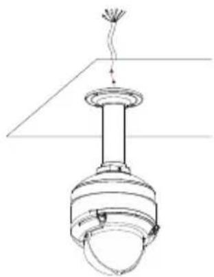
YcTaHOBka NODBeCHOrO KPOHHTeHa (OnuHaJIbHo)
PnKpeNte HxHIOI NaHeJIb OCHOBaHna KaMepbl K KpbIuKe KPOHSTeHa C NOMOUsbU YeTbIpex BXODAUX B KOMnJIeKT NOCTaBKn BNHTOB.
BbI6epnte noDxOJaIee MeCTo Ha nOTOnke Inra TORO, UTO6bl npocBepnITb OTBepCTne DnaMeTpom 34 MM (+2 / - 0MM) .NcnoJIb3yIte BXODaIuB KOMnJIeKT NOCTaBKn 1a6JIoH, UTO6bl pa3MeTHTb N BbIpe3aTb MOHTaXHbIe OTBepCTnIa.
BbIbePte noDxOJaUee MeCTo Ha nOTOnKe dIa TORO, UTO6bI npocBepnITb OTBepCTne DnaMeTpom 34 MM (+2 / - 0MM) .NcnoJIb3yIe BxOJaUIM B KOMnJIeKT NOCTaBKn Ia6JIoH, UTO6bI pa3MeTtB N Bblpe3aTb OTBepCTne dIra Ka6JIeNe.
PrcBepIte YeTbipe OTBepCTnA NaMeTpom 6 MM, COOTBETCTByIOUne OTBepCTnM Ha Ia6JIoHe, IN BCTaBbTe B HIX PJIaCTMaCCOBbIe aHKepbI.
IomeCTnte pe3HOBbI yNIOHTHeJIb MeJy NOBBeCHbIM KPOHHTeHOM I NOTOLKOM DnIy OBeCneHnRA BODOHnPoHnCaEMOCTn MEJy NOTOLKOM IN KPOHHTeHOM.
PpHKpeHnTe NOBecHO KPOHHTeH K NOTOKy C NOMOuB BXoJxN B KOMnEKT NOCTaBKN BINTOB.
PpIKpeNITe KpbIshky CHN3y NOdBecHOrO KPOHHTeHa, NOBOPaUNBa eE npOTnB YacBOB CTpeJIKN Do NOnHOJ FHKcaUH.
BCTaBbTe BnHT B OCHOBaHne NOdBecHO KPOHHTeHa CBepxu KpbIuK, YTo6bl 3aΦNKcnpoBaTb ee.
IpoTaNTe Ethernet-Ka6eNb N Ka6eNb NITaHnY Upe3 NOBecHO KPOHSTeH.
IomeCTnte KaMepy Ha KpbIuKy KpoHSteHa n
IprNKpeNTE KyIOJI K OCHOBaHnIO KaMepbIC NOMOuIO
YeTbIPex DInHHbIX BnHTOB IN 3aUINTHOrO BNHTa.
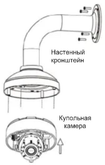
YcTaHOBka HacTeHHoro KpoHsTeiHa (OПцИОньHo)
PnKpeNITe HxHIOI NaHeJIb OCHOBaHnKaMepbl K KpbIuKe KPOHHTeHa C NOMOUsIO YETbIPEx BXODAUX B KOMPiEKT NOCTABKN BINTOB.
BbI6epnte noDxOJaIee MeCTo Ha nOTOnke Inra TORO, UTO6bl npocBepnITb OTBepCTne DnaMeTpom 34 MM (+2 / - 0MM) .NcnoJIb3yIte BxoJauN B KOMnIeKT NOCTaBKn 1a6JIOH, UTO6bl pa3MeNTb N BbIpe3aTb MOHTaXHbIe OTBepCTnR.
PrcBepnTe YeTbIpe OTBepCTnA dmameTpom 6 MM, COOTBETCTByUOuNE OTBepCTnM Ha Ia6NoHe, IN BCTaBbTe B Hnx PJIaCTMaCCOBbIe aHKepbI.
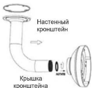
IomeCTHTe pe3HOBbI yNIOHTHNTeJIb MeJy HAcTeHHbIM KPOHSTeHOM I NOTOLKOM DJIa OBeCneHnBaOHOENpOHNuCaEMoCTn MeJy NOTOLKOM IN KPOHSTeHOM.
PnKpeNte HacTeHbI KPOHSTeH K NOTOKy C NOMOuB BXoAUX B KOMPNeKT NOCTaBKIN BHTOB.
PpIKpeNITe KpbIshky CHN3y HAcTeHHOrO KPOHSTeHa, NOBOPaUHBaey npOTnB YacOBoN CTpeJIKN Do NOLHOI KCaUN.
BCTaBbTe BnHT B OCHOBaHHe HAcTeHHoro KpoHsTeHa CBepxu KpbIuK, YTO6bl 3aΦnKcnpoBaTb ee.
IpoTaNHe Ethernet-Ka6eNb N Ka6eNb NITaHnY Upe3 HAcTeHHbIKPOHsTeiH.
IomeCTnte KaMepy Ha KpbIshky KpoHsTeiHa I npIKpeNte KynoJ K OCHOBaHNIO KaMepbIC NOMOuO ueTbipex DnHHbIX BnHTOB IN 3aUHTHO BVHTa.
Подклоченье камеры
PoiKJIouHHe c nOmoIbIO PoE-koMMyTaTopa
He nCnoIb3yIte yCTpoIcTBO c noBpeJdeHbIM KOpnycom. Tempepatya
OKpykaIOUeI CpeDbI B HeNOCpeIDCTBeHHoH 6JIIN3OCTN OT yCTpOJCTBa I BHyTpN erO KOpnyCa DOJIKHa COOTBETCTBOBaTb yKa3aHHoH B TEXHnueCKNX XapaKTepnCTNKax YCTPOJCTBa.
Bo n36exaHne noBpeJdeHnMaTpNcbl He HappaBnTe oBeKtNB BnDeOKaMepbHa ouHenb JApKHe oBeKtbl N CoJIHcE.
He BkIouaIte aadantep nItaHnra*, eCNI erO kOpNyc nII KabeJIb noBpeJdeHbl.
IodKnIOuAte aadTep nHTaHnra* TOnbKO K nCnpaBHBIM pO3eTKam C npaMeTpamN, yKa3aHHbIM Na aadTpe nHTaHnra*.
He BckpbIbAaTe KOpnyc ycTpoiCTBa! Npeed OuncTKoK KaMepbI OT 3aRpa3HeHIn n PbJIIN OTKIOUHTe PNTaHne ycTpoiCTBa. YdaJIte PbJbC nOMOuB BnaXHOc anfoETKn. He nCnoJIb3yIte JxIDKne/a3pO3OJbHbIe OuncTIteJIu INI MaHHTHbIe/ CTaTNUeCKne ycTPOiCTBa dJa OuncTKn. I36eaiTe nonaDaHnB bIaRn B ycTPOiCTBO n aAdanTeP NiTaHnra*.
Cpok cnjxkbiy yctpoicTba - 2 roda.
TapaHTnHbI NepNO, nCUncJIaTeC T C MOMeHTa npNo6peTeHn yCTpoiCTBa y oΦnuaJIbHO rO dInepa Ha TeppuToPn PocCn n CTpaH CHr n CoCTabJIaE T Odn H. roD.
BHe 3aBnCIMOCTN OT DaTbI npoJaxn rapaHTnHbI cPOK He MoKe TnpEByIaTb 2 roDa C daTbI npOn3BOIDCTBa n3deJIy, KOtOpA onpeJeIeTcR no 6 (roD) n7 (MecaU) cInppam cepiHoro HOMepa, yka3aHHoro Ha NaKeIke C TexHnueckmN daHHbIMN.
Год: 9 - 2009, A - 2010, B - 2011, C - 2012, D - 2013, E - 2014, F - 2015, G - 2016, H - 2017.
AnMaTbI, KypMaHaFa3bI K-ci,143 y
Ten.: +7 (727) 378-55-90
E-mail: almaty@dlink.ru

zuiuunu
Epuu, Tuulpuu2tu 3-
puunuuluu,23/5
2tn. +374 (10) 39-86-67
E1. qnuun.info@dlink.am
Latvija
Riga,Lielirbesiela 27
Tel.: +371 (6) 761-87-03
E-mail: info@dlink.lv
Lietuva
Vilnius, Žirmūnú 139-303
Tel.: +370 (5) 236-36-29
E-mail: info@dlink.lt
Eesti
E-mail: info@dlink.ee
Türkiye
Uphill Towers Residence A/99
Atasehir /ISTANBUL
Tel: +90 (216) 492-99-99
Email: info.tr@dlink.com.tr
7
20 1
170n
nnn
972 (3) 921-28-86
support@dlink.co.il
Guia de instalação

Select Language English
For security, it is recommended to change the password for your administration account.

Optional Cable Harness (not included)
Regulatory Statements (Only for Class A product)
Federal Communication Commission Interference Statement
This equipment has been tested and found to comply with the limits for a Class A digital device, pursuant to part 15 of the FCC Rules. These limits are designed to provide reasonable protection against harmful interference when the equipment is operated in a commercial environment. This equipment generates, uses, and can radiate radio frequency energy and, if not installed and used in accordance with the instruction manual, may cause harmful interference to radio communications. Operation of this equipment in a residential area is likely to cause harmful interference in which case the user will be required to correct the interference at his own expense.
Non-modification Statement
Any changes or modifications not expressly approved by the party responsible for compliance could void the user's authority to operate the equipment.
Caution
This device complies with Part 15 of the FCC Rules. Operation is subject to the following two conditions:
(1) This device may not cause harmful interference, and (2) this device must accept any interference received, including interference that may cause undesired operation.
Innovation, Science and Economic Development Canada (ISED) Statement:
This Class A digital apparatus complies with Canadian ICES-003.
CE EMI Class A Warning
This equipment is compliant with Class A of CISPR 32. In a residential environment this equipment may cause radio interference.
Regulatory Statements (Only for Class B product)
Federal Communication Commission Interference Statement
This equipment has been tested and found to comply with the limits for a Class B digital device, pursuant to Part 15 of the FCC Rules. These limits are designed to provide reasonable protection against harmful interference in a residential installation. This equipment generates, uses and can radiate radio frequency energy and, if not installed and used in accordance with the instructions, may cause harmful interference to radio communications. However, there is no guarantee that interference will not occur in a particular installation. If this equipment does cause harmful interference to radio or television reception, which can be determined by turning the equipment off and on, the user is encouraged to try to correct the interference by one of the following measures:
- Reorient or relocate the receiving antenna.
- Increase the separation between the equipment and receiver.
- Connect the equipment into an outlet on a circuit different from that to which the receiver is connected.
- Consult the dealer or an experienced radio/TV technician for help.
Non-modification Statement
Any changes or modifications not expressly approved by the party responsible for compliance could void the user's authority to operate the equipment.
Caution
This device complies with Part 15 of the FCC Rules. Operation is subject to the following two conditions: (1) This device may not cause harmful interference, and (2) this device must accept any interference received, including interference that may cause undesired operation.
Innovation, Science and Economic Development Canada (ISED) Statement:
This Class B digital apparatus complies with Canadian ICES-003.
This equipment is compliant with Class A of CISPR 32. In a residential environment this equipment may cause radio interference.
SAFETY INSTRUCTIONS
The following general safety guidelines are provided to help ensure your own personal safety and protect your product from potential damage. Remember to consult the product user instructions for more details.
- Static electricity can be harmful to electronic components. Discharge static electricity from your body (i.e. touching grounded bare metal) before touching the product.
- Do not attempt to service the product and never disassemble the product. For some products with a user replaceable battery, please read and follow the instructions in the user manual.
- Do not spill food or liquid on your product and never push any objects into the openings of your product.
- Do not use this product near water, areas with high humidity, or condensation unless the product is specifically rated for outdoor application.
- Keep the product away from radiators and other heat sources.
- Always unplug the product from mains power before cleaning and use a dry lint free cloth only.
DISPOSING AND RECYCLING YOUR PRODUCT

This symbol on the product or packaging means that according to local laws and regulations this product should be not be disposed of in the household waste but sent for recycling. Please take it to a collection point designated by your local authorities once it has reached the end of its life, some will accept products for free. By recycling the product and its packaging in this manner you help to conserve the environment and protect human health.
CE EMI KLASSE A-WAARSCHUWING
AFVALVERWERKING EN RECYCLING VAN UW PRODUCT

MISE AU REBUT ET RECYCLAGE DE VOTRE PRODUIT

IPOEIANOIHCEEMKAAHSA
VIDVÖRUN FYRIR CE EMI FLOKK A
UTYLIZACJA I RECYKLING PRODUKTU

Slovenian [Slovenski]
OPOZORILO CE EMI ZA RAZRED A
DESECHAR Y RECICLAR EL PRODUCTO

CE EMI KLASS A-VARNING
This D-Link product includes software code developed by third parties, including software code subject to the GNU General Public License ("GPL") or GNU Lesser General Public License ("LGPL"). As applicable, the terms of the GPL and LGPL, and information on obtaining access to the GPL code and LGPL code used in this product, are available to view the full GPL Code Statement at:
The GPL code and LGPL code used in this product is distributed WITHOUT ANY WARRANTY and is subject to the copyrights of one or more authors. For details, see the GPL code and the LGPL code for this product and the terms of the GPL and LGPL.
Written Offer for GPL and LGPL Source Code
Where such specific license terms entitle you to the source code of such software, D-Link will provide upon written request via email and/or traditional paper mail the applicable GPL and LGPLsource code files via CD-ROM for a nominal cost to cover shipping and media charges as allowed under the GPL and LGPL.
Please direct all inquiries to:
Email:
GPLCODE@dlink.com
Snail Mail:
Attn:GPLSOURCE REQUEST
D-Link Systems, Inc.
Fountain Valley, CA 92708
Notes
Notes
Notes
Notes
D-Link

Ver. 2.01(WW)_130x183
2018/10/05
0420123/1-DL

- Quick Installation Guide
- Megapixel H.265 Outdoor Dome Network Camera
- Package Contents
- Safety Notice:
- Hardware Overview
- Optional Cable Harness (not included)
- Connecting the Optional Cable Harness
- microSD Card Installation
- Mounting the Camera on the Ceiling
- Adjusting the Camera's Lens
- Installing the Pendant Mount (Optional)
- Installing the Right-Angle Mount (Optional)
- Connecting the Camera
- Connection with a PoE Switch
- General Connection Using 12 V DC Power Adapter (not included)
- Configuring the Camera
- Viewing Your Camera via a Web Browser
- Additional Information
- Warranty Information
- KpaTkoe pykoBODCTBO NO yCTaHOBKe
- YctaHOBka KapTbI microSD
- YcTaHOBka KaMepbI Ha NOTOJIke
- PergunpoBka obBeKTHBa kamepbI
- YcTaHOBka NODBeCHOrO KPOHHTeHa (OnuHaJIbHo)
- YcTaHOBka HacTeHHoro KpoHsTeiHa (OПцИОньHo)
- Подклоченье камеры
- PoiKJIouHHe c nOmoIbIO PoE-koMMyTaTopa
- Guia de instalação
- Regulatory Statements (Only for Class A product)
- Federal Communication Commission Interference Statement
- Non-modification Statement
- Caution
- Innovation, Science and Economic Development Canada (ISED) Statement:
- CE EMI Class A Warning
- Regulatory Statements (Only for Class B product)
- SAFETY INSTRUCTIONS
- DISPOSING AND RECYCLING YOUR PRODUCT
- AFVALVERWERKING EN RECYCLING VAN UW PRODUCT
- MISE AU REBUT ET RECYCLAGE DE VOTRE PRODUIT
- IPOEIANOIHCEEMKAAHSA
- VIDVÖRUN FYRIR CE EMI FLOKK A
- UTYLIZACJA I RECYKLING PRODUKTU
- Slovenian [Slovenski]
- OPOZORILO CE EMI ZA RAZRED A
- DESECHAR Y RECICLAR EL PRODUCTO
- CE EMI KLASS A-VARNING
- Written Offer for GPL and LGPL Source Code
- Email:
- Snail Mail:
- Notes
- D-Link
Brand : D-LINK
Model : DCS6517
Category : Surveillance Camera