EM4350RH - Grass trimmer MAKITA - Free user manual and instructions
Find the device manual for free EM4350RH MAKITA in PDF.
User questions about EM4350RH MAKITA
0 question about this device. Answer the ones you know or ask your own.
Ask a new question about this device
Download the instructions for your Grass trimmer in PDF format for free! Find your manual EM4350RH - MAKITA and take your electronic device back in hand. On this page are published all the documents necessary for the use of your device. EM4350RH by MAKITA.
USER MANUAL EM4350RH MAKITA
Read this instruction manual carefully before putting the Petrol Backpack Brushcutter into operation and strictly observe the safety regulations!
Preserve instruction manual carefully!
Important :
natural_image
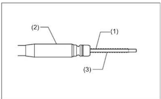
Line drawing of a portable electric shock absorber with attached circuit board (no text or symbols)EM4350RH
English
(Original instructions)
Thank you very much for purchasing the MAKITA Outdoor Power Equipment. We are pleased to recommend to you the MAKITA product which is the result of a long development program and many years of knowledge and experience. Please read this booklet which refers in detail to the various points that will demonstrate its outstanding performance. This will assist you to obtain the best possible result from your MAKITA product.

Table of Contents Page
Symbols 2
Safety instructions ....3
Technical data....7
Designation of parts....8
Mounting of handle 9
Mounting of flexible shaft 10
Mounting of protector....11
Mounting of metal blade or nylon cutting head .....13
Before start of operation 14
Correct handling of machine....16
How to start and stop engine 18
Resharpening the cutting tool 21
Servicing instructions....23
Storage 27
Troubleshooting 29
SYMBOLS
You will note the following symbols when reading the instructions manual.

Read instruction manual and follow the warnings and safety precautions!

Take Particular care and attention!

Forbidden!

Keep distance!

Flying object hazard!

Kickback!

No smoking!

No open flame!

Protective gloves must be worn!

Wear sturdy boots with nonslip soles. Steeltoed safety boots are recommended!

Keep the area of operation clear of all persons and pets!

Wear protective helmet, eye and ear protection!

Top permissible tool speed

Fuel (Gasoline)

Engine-manual start

Emergency stop

First Aid

ON/START

OFF/STOP
SAFETY INSTRUCTIONS
General Instructions
- Read this instruction manual to become familiar with handling of the equipment. Users insufficiently informed will risk danger to themselves as well as others due to improper handling.
- It is recommended only to lend the equipment to people who have proven to be experienced.
Always hand over the instruction manual.
- First users should ask the dealer for basic instructions to familiarize oneself with the handling of brushcutters.
- Children and young persons aged under 18 years must not be allowed to operate this equipment. Persons over the age of 16 years may however use the device for the purpose of being trained while under supervision of a qualified trainer.
- Use with the utmost care and attention.
- Operate only if you are in good physical condition. Perform all work calmly and carefully. The user has to accept liability for others.
- Never use this equipment after consumption of alcohol or drugs, or if feeling tired or ill.
- National regulation can restrict the use of the machine.
Intended use of the machine
- This equipment is only intended for cutting grass, weeds, bushes, undergrowth. It should not be used for any other purpose such as edging or hedge cutting as this may cause injury.
Personal protective equipment
- The clothing worn should be functional and appropriate, i.e. it should be tight-fitting but not cause hindrance. Do not wear either jewelry or clothing which could become entangled with bushes or shrubs.
- In order to avoid either head-, eye-, hand-or foot injuries as well as to protect your hearing the following protective equipment and protective clothing must be used during operation.
- Always wear a helmet where there is a risk of falling objects. The protective helmet (1) is to be checked at regular intervals for damage and is to be replaced at the latest after 5 years. Use only approved protective helmets.
- The visor (2) of the helmet (or alternatively goggles) protects the face from flying debris and stones. During operation always wear goggles, or a visor to prevent eye injuries.
- Wear adequate noise protection equipment to avoid hearing impairment (ear muffs (3), ear plugs etc.).
- The work overalls (4) protect against flying stones and debris. We strongly recommend that the user wears work overalls.
- Gloves (5) are part of the prescribed equipment and must always be worn during operation.
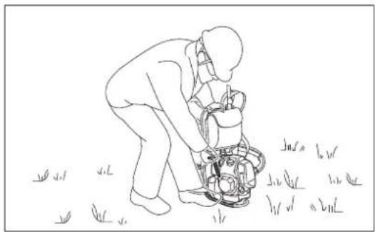
- When using the equipment, always wear sturdy shoes (6) with a non-slip sole. This protects against injuries and ensures a good footing.
Starting up the brushcutter
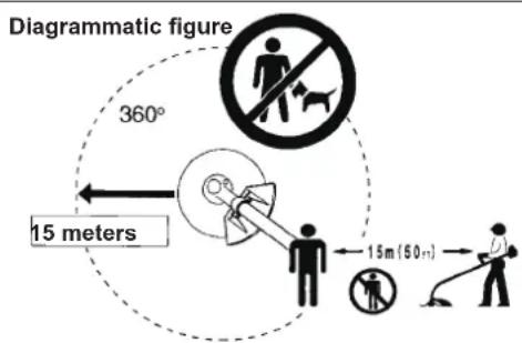
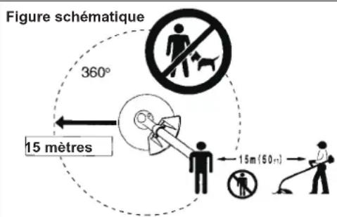
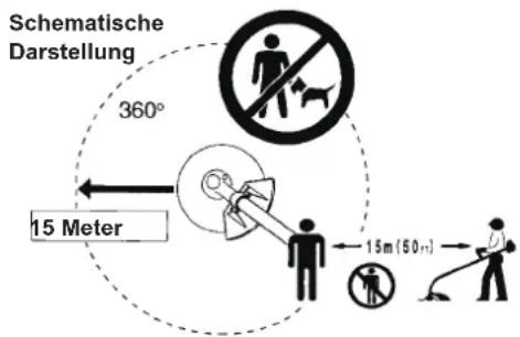
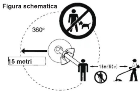
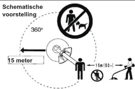
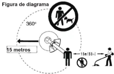
- Make sure that there are no children or other people within a working range of 15 meters (50 ft), also pay attention to any animals in the working vicinity.
- Before use always check the equipment is safe for operation:
Check the security of the cutting tool, the throttle lever for easy action and check for proper functioning of the throttle lever lock. - Rotation of the cutting tool during idling speed is not allowed. Check with your dealer for adjustment if in doubt. Check for clean and dry handles and test the function of the start/stop switch.


text_image
Warning symbol with exclamation mark inside a triangle
natural_image
Black-and-white illustration of wine bottles and a pen with a crossed arrow, no text or symbols present

(3)


(5)

(6)
text_image
Diagrammatic figure 360° 15 meters 15m (50 ft)Start the brushcutter only in accordance with the instructions.
- Do not use any other methods for starting the engine!
- Use the brushcutter and the tools only for such applications as specified.
- Only start the engine, after the entire assembly is done. Operation of the device is only permitted after all the appropriate accessories are attached!
- Before starting make sure that the cutting tool has no contact with hard objects such as branches, stones etc. as the cutting tool will revolve when starting.
- The engine is to be switched off immediately in case of any engine problems.
- Should the cutting tool hit stones or other hard objects, immediately switch off the engine and inspect the cutting tool.
- Inspect the cutting tool at short regular intervals for damage (detection of hairline cracks by means of tapping-noise test).
- If the equipment gets heavy impact or fall, check the condition before continuing work. Check the fuel system for fuel leakage and the controls and safety devices for malfunction. If there is any damage or doubt, ask our authorized service center for the inspection and repair.
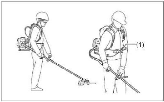
- Operate the equipment only with the harness attached which is to be suitably adjusted before putting the brushcutter into operation. It is essential to adjust the harness according to the user size to prevent fatigue occurring during use. Never hold the cutter with one hand during use.
- During operation always hold the brushcutter with both hands.
Always ensure a safe footing.
- Operate the equipment in such a manner as to avoid inhalation of the exhaust gases. Never run the engine in enclosed rooms (risk of gas poisoning). Carbon monoxide is an odorless gas.
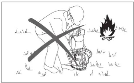
- Switch off the engine when resting and when leaving the equipment unattended, and place it in a safe location to prevent danger to others or damage to the machine.
- Never put the hot brushcutter onto dry grass or onto any combustible materials.
- Always install the approved cutting tool guard onto the equipment before starting the engine.
Otherwise contact with the cutting tool may cause serious injury.
- All protective installations and guards supplied with the machine must be used during operation.
- Never operate the engine with faulty exhaust muffler.
- Shut off the engine during transport.
- When transporting the equipment, always attach the cover to the metal blade.
- Ensure safe position of the equipment during car transportation to avoid fuel leakage.
- When transporting, ensure that the fuel tank is completely empty.
- When unloading the equipment from the truck, never drop the Engine to the ground or this may severely damage the fuel tank.
- Except in case of emergency, never drop or cast the equipment to the ground or this may severely damage the equipment.
Refuelling
- Shut off the engine during refuelling, keep away from open flames and do not smoke.
- Avoid skin contact with mineral oil products. Do not inhale fuel vapor. Always wear protective gloves during refuelling. Change and clean protective clothing at regular intervals.
- Take care not to spill either fuel or oil in order to prevent soil contamination (environmental protection). Clean the brushcutter immediately after fuel has been spilt.
- Avoid any fuel contact with your clothing. Change your clothing instantly if fuel has been spilt on it (to prevent clothing catching fire).
- Inspect the fuel cap at regular intervals making sure that it can be securely fastened and does not leak.
- Carefully tighten the fuel tank cap. Change location to start the engine (at least 3 meters away from the place of refuelling).
- Never refuel in closed rooms. Fuel vapors accumulate at ground level (risk of explosions).
- Only transport and store fuel in approved containers. Make sure the fuel stored is not accessible to children.
• Always refuel on stable flat surface to avoid fuel spillage.
natural_image
Line drawing of a person operating a lawn mower in grass (no text or symbols)
natural_image
Line drawing of a person wearing a full-body medical harness and holding a tool (no text or symbols)
text_image
STOP • Resting • Transport • Refuelling • Maintenance • Tool replacement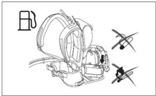
natural_image
Line drawing of a helicopter with three additional aircraft flying nearby (no text or symbols)
text_image
3 metersMethod of operation
- Only use in good light and visibility. During the winter season beware of slippery or wet areas, ice and snow (risk of slipping). Always ensure a safe footing.
- Never cut above waist height.
- Never stand on a ladder.
- Never climb up into trees to perform cutting operation.
- Never work on unstable surfaces.
- Remove sand, stones, nails etc. found within the working range.
Foreign particles may damage the cutting tool and can cause dangerous kickbacks.
- Before commencing cutting, the cutting tool must have reached full working speed.
- When using metal blades, swing the tool evenly in half-circle from right to left, like using a scythe.
If grass or branches get caught between the cutting tool and guard, always stop the engine before cleaning. Otherwise unintentional blade rotation may cause serious injury.
- Take a rest to prevent loss of control caused by fatigue. We recommend to take a 10 to 20-minute rest every hour.
- Do not let the cutting tool touch on the ground during operation. Otherwise the cutting tool hit an object and may result in personal injury.
- Keep the metal blade parallel with the ground during operation.
Cutting Tools
- Use an applicable cutting tool for the job in hand.
Nylon cutting heads (string trimmer heads) are suitable for trimming lawn grass.
Metal blades are suitable for cutting weeds, high grasses, bushes, shrubs, underwood, thicket, and the like.
Never use other blades including metal multi-piece pivoting chains and flail blades. Otherwise serious injury may result.
- When using metal blades, avoid "Kickback" and always prepare for an accidental kickback. See the section "Kickback".
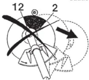
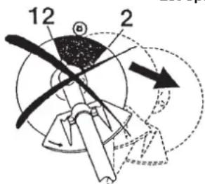
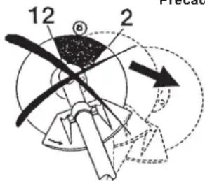
Kickback (blade thrust)
- Kickback (blade thrust) is a sudden reaction to a caught or bound metal blade. Once it occurs, the equipment is thrown sideway or toward the operator at great force and it may cause serious injury.
- Kickback occurs particularly when applying the blade segment between 12 and 2 o'clock to solids, bushes and trees with 3cm or larger diameter.
- To avoid kickback:
- Apply the segment between 8 and 11 o'clock;
- Never apply the segment between 12 and 2 o'clock;
- Never apply the segment between 11 and 12 o'clock and between 2 and
5 o'clock, unless the operator is well trained and experienced and does it at his/her own risk;
- Never use metal blades close to solids, such as fences, walls, tree trunks and stones;
– Never use metal blades vertically, for such operations as edging and trimming hedges.
Vibration
- People with poor circulation who are exposed to excessive vibration may experience injury to blood vessels or the nervous system. Vibration may cause the following symptoms to occur in the fingers, hands or wrists: "Falling asleep" (numbness), tingling, pain, stabbing sensation, alteration of skin color or of the skin. If any of these symptoms occur, see a physician!
- To reduce the risk of "white finger disease", keep your hands warm during operation and well maintain the equipment and accessories.
Maintenance instructions
- Have your equipment serviced by our authorized service center, always using only genuine replacement parts. Incorrect repair and poor maintenance can shorten the life of the equipment and increase the risk of accidents.
- The condition of the cutter, in particular of the cutting tool of the protective devices and also of the harness must be checked before commencing work. Particular attention is to be paid to the metal blades which must be correctly sharpened.
- Turn off the engine and remove spark plug connector when replacing or sharpening cutting tools, and also when cleaning the cutter or cutting tool.

text_image
Warning sign depicting a person using a tool to avoid accidents, with arrows indicating direction and symbols for visibility.Caution: Kickback
text_image
12 2
Diagrammatic figure

text_image
12 11 2 9 8 3 6 5
Diagrammatic figure

natural_image
Line drawing of a person using a metal detector on a tripod (no text or symbols)Never straighten or weld damaged cutting tools.
- Pay attention to the environment. Avoid unnecessary throttle operation for less pollution and noise emissions. Adjust the carburetor correctly.
- Clean the equipment at regular intervals and check that all screws and nuts are well tightened.
- Never service or store the equipment in the vicinity of naked flames.
- Always store the equipment in locked rooms and with an emptied fuel tank.
- When cleaning, servicing and storing the equipment, always attach the cover to the metal blade.
text_image
Illustration showing a person using a power tool with crossed-out tools, alongside a campfire and grass symbols.Observe the relevant accident prevention instructions issued by the relevant trade associations and by the insurance companies.
Do not perform any modifications to the equipment as this will endanger your safety.
The performance of maintenance or repair work by the user is limited to those activities as described in the instruction manual. All other work is to be done by an Authorized Service Agent. Use only genuine spare parts and accessories released and supplied by MAKITA.
Use of non-approved accessories and tools means increased risk of accidents.
MAKITA will not accept any liability for accidents or damage caused by the use of non-approved cutting tools and fixing devices of cutting tools, or accessories.
First Aid
In case of accident make sure that a first-aid box is available in the vicinity of the cutting operations. Immediately replace any item taken from the first aid box.
When asking for help, please give the following information:
- Place of accident
• What happened
• Number of injured persons - Kind of injuries
- Your name

natural_image
Simple black plus sign inside a square (no text or symbols)For European countries only
EC Declaration of Conformity
The EC declaration of conformity is included as Annex A to this instruction manual.
TECHNICAL DATA
| Model EM4350RH | ||||
| Handle type | Loop handle | |||
| Dimensions: length x width x height (without flexible / straight shaft part) mm | 358 x 280 x 587 | |||
| Mass (without plastic guard and cutting tool) kg | 12.1 | |||
| Volume (fuel tank) L | 0.8 | |||
| Volume (oil tank) L | 0.1 | |||
| Engine displacement cm 3 | 43.0 | |||
| Maximum engine performance kW | 1.5 at 7,500 min-1 | |||
| Engine speed at recommended max. spindle speed min -1 | 10,500 | |||
| Maximum spindle speed (corresponding) min -1 | 7,200 | |||
| Idling speed min -1 | 3,000 | |||
| Clutch engagement speed min -1 | 4,000 | |||
| Carburetor | Diaphragm type | |||
| Spark plug type | NGK CMR6A | |||
| Electrode gap mm | 0.7 – 0.8 | |||
| CUTTER BLADE NYLON CUTTING HEAD | ||||
| Vibration per ISO 22867 | Right handle (Rear grip) | ahv eq m/s2 | 2.7 2.4 | |
| Uncertainty K m/s2 | 0.8 0.7 | |||
| Left handle (Front grip) | ahv eq m/s2 | 3.2 3.4 | ||
| Uncertainty K m/s2 | 1.7 1.0 | |||
| Sound pressure level average to ISO 22868 | LPA eq dB (A) | 83.5 | 92.5 | |
| Uncertainty K dB (A) | 1.1 1.7 | |||
| Sound power level average to ISO 22868 | LWA eq dB (A) | 104.1 | 110.6 | |
| Uncertainty K dB (A) | 1.1 0.7 | |||
| Fuel | Automobile gasoline (petrol) | |||
| Engine Oil | API grade SF class or higher, SAE 10W-30 oil (automobile 4-stroke engine oil) | |||
| Cutting tools (cutter blade dia.) mm | 440 (with nylon cutting head), 255 (with 4-tooth blade), 255 (with 3-tooth blade), 305 (with 2-tooth blade) | |||
| Gear ratio | 13/19 | |||
- Due to our continuing program of research and development, the specifications herein are subject to change without notice.
- Specifications may differ from country to country.
text_image
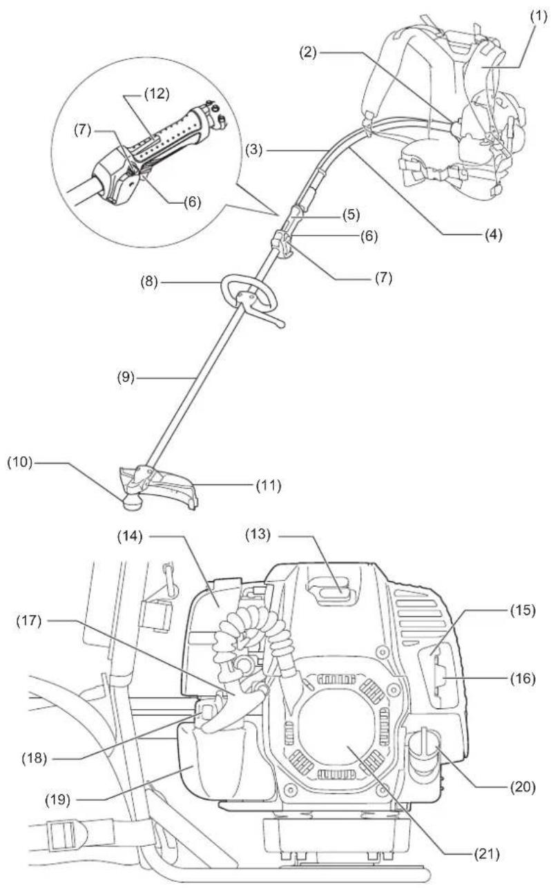
Technical diagram of a mechanical device with numbered parts and an inset showing a component labeled (12) and (7).| 1. Harness 2. Clutch case 3. Control cable 4. Flexible shaft | ||
| 5. Rear grip 6. Throttle lever 7. I-O switch (on/off) 8. Handle | ||
| 9. Straight shaft 10. Gear case 11. Protector (Cutting tool guard) 12. Lock-off lever | ||
| 13. Spark plug 14. Air cleaner 15. Exhaust muffler 16. Exhaust pipe | ||
| 17. Starter knob 18. Fuel tank cap | 19. Fuel tank 20. Oil cap | |
| 21. Recoil starter |
MOUNTING OF HANDLE
CAUTION:
- Before doing any work on the equipment, always stop the engine and pull the spark plug connector off the spark plug.
• Always wear protective gloves!
CAUTION:
- Start the engine only after having assembled it completely.
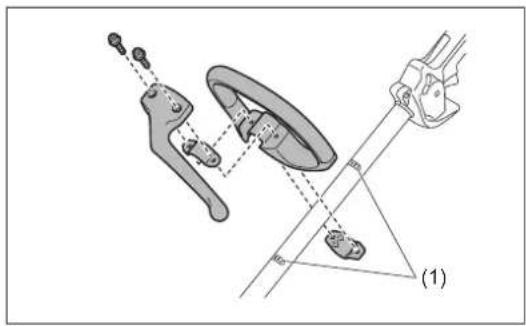
• Fix the loop handle on the shaft with two screws.
- To keep a proper distance between the grips, place the handle between the arrow marks (1) on the shaft.
text_image
Technical diagram showing mechanical assembly with labeled parts and dimension linesMOUNTING OF FLEXIBLE SHAFT
Mounting the flexible shaft
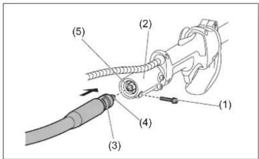
- Remove the bolt (1) from the end of the straight shaft (2).
- Remove the cap from the flexible shaft.
NOTE:
- Do not lose the cap. Always put the cap when removing the flexible shaft.
- Turn the flexible shaft so that the dented part (3) of the flexible shaft faces downwards.
- Align the square inner shaft (4) with the joint hole (5). Insert the end of the flexible shaft into the pipe holder all the way.
- Tighten them with the bolt (1).
NOTICE:
- If it is difficult to insert the flexible shaft, align the square inner shaft (4) again.
-
Do not pull out the inner shaft more than 35 mm (1-1/3").
-
Align the hole (7) on the other end of flexible shaft with the knob (8) of the clutch case (6), and insert the flexible shaft into the clutch case.
- Make sure the knob clicks as the knob fits into the hole of the flexible shaft.
To remove the flexible shaft from the clutch case, pull up the knob and remove it.
Connecting the control cable
- Fit the end of the control cable from the control lever (2) onto the end of the control cable from the engine (3).
- Place the control cable from the control lever in the connector (1). And then close the connector.
- Make sure the throttle in the carburetor moves simultaneously when pulling the throttle lever.
Connecting the lead unit
Connect the lead units from the engine (1) with the lead units from the control lever (2) as each male and female terminals are connected.
Securing the control cable
Secure the control cable (1) to the flexible shaft by using two clamps (2) and another clamp (3) as illustrated.

CAUTION:
- Make sure the control cable is attached to the flexible shaft properly. Loose cable may catch the branches etc. and result in personal injury.
- Do not twine the control cable around the flexible shaft. Otherwise the throttle may not work properly.
text_image
(1) (2) (3) (4) (5)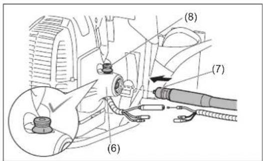
text_image
(8) (7) (6)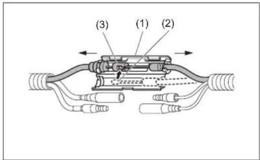
text_image
(3) (1) (2)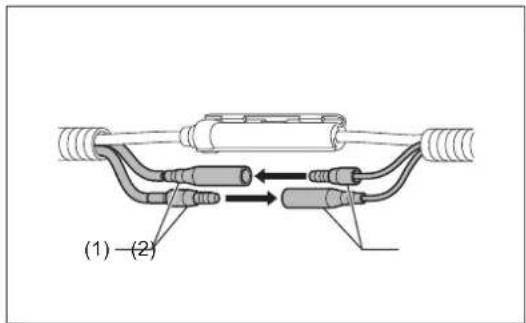
text_image
(1) - (2)
text_image
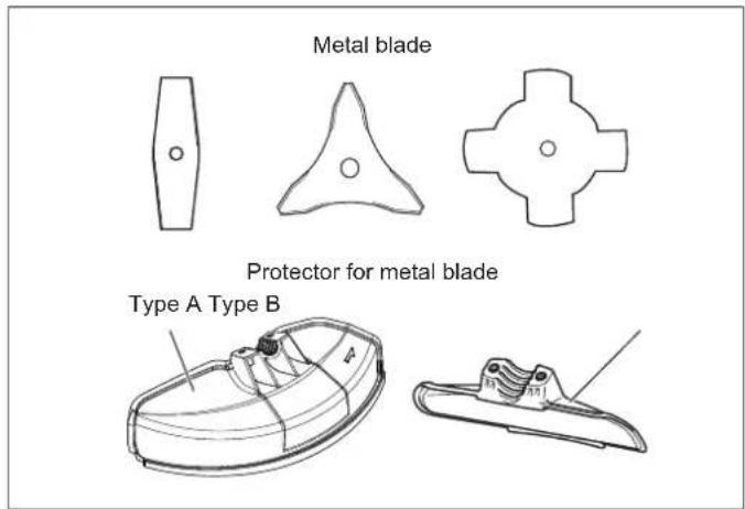
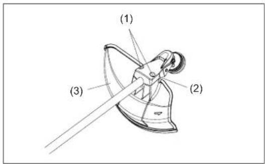
(1) (2) (3)MOUNTING OF PROTECTOR
To meet the applicable safety provisions, only the tool/protector combinations as indicated in the table must be used.

CAUTION:
- The appropriate protector must always be installed, for your own safety and in order to comply with accident prevention regulations. Operation of the equipment without the guard being in place is not permitted. Do not apply other combination when using saw-blade.
NOTE:
- The standard combination of cutting tool differs from county to country.
text_image
Metal blade Protector for metal blade Type A Type B| Nylon cutting head | Protector for nylon cutting head |
| Protector for nylon cutting head |
For metal blades

CAUTION:
- Make sure that the protector tightening bolts are tightened evenly so that the gap between the clamp and the protector will be constant. Otherwise, the protector sometimes may not function as specified.
(For Type A protector)
Fix the protector (3) to the clamp (2) with two bolts M6x30 (1).
(For Type B protector)
Fix the protector to the clamp (4) with two bolts M6x18 (5).
If the protector cover (6) is installed on the shaft, remove it first as follows.
-
Remove the washers (7), bolts M6x30 (8) from protector cover.
-
Remove the protector cover by slightly spreading the fin (9).
NOTE:
- When changing the protector from Type B to Type A, install the protector cover, bolts M6x30 and washers onto the shaft before installing the protector.
text_image
(1) (2) (3)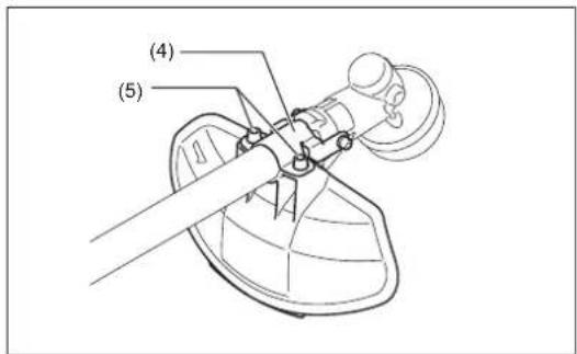
text_image
(4) (5)
text_image
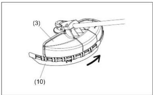
(8) (6) (7) (9)For nylon cutting head
- Be sure to mount the nylon cutting head protector (10) onto the type A metal blade protector (3) assembled with the nylon cutting head protector.
- Mount the nylon cutting head protector (10) by sliding it into place from the flank of the metal blade protector (3).
- Remove tape adhered to cutter, which cuts nylon cord, on nylon cutting head protector (10).

CAUTION:
- Be sure to push in nylon cutting head protector (10) until it is fully inserted. Take care not to injure yourself on the cutter for cutting the nylon cord.
- To remove the nylon cutting head protector (10), apply a hex wrench (11) into the notch on the metal blade protector (3), push it in and meanwhile slide the nylon cutting head protector (10).
text_image
(3) (10)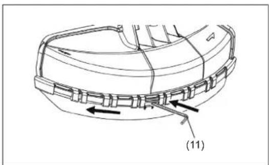
natural_image
Technical line drawing of a mechanical component with labeled parts (11), showing internal structure and arrows indicating movement or force (no text or symbols beyond label)MOUNTING OF METAL BLADE OR NYLON CUTTING HEAD
Be sure to use genuine MAKITA metal blades or nylon cutting head.
- The metal blade must be well polished, free of cracks or breakage. If the metal blade hits against a stone during operation, stop the engine and check the blade immediately.
- Polish or replace the metal blade every three hours of operation.
- If the nylon cutting head hits against a stone during operation, stop the engine and check the nylon cutting head immediately.

CAUTION:
- The appropriate protector must always be installed, for your own safety and in order to comply with accident-prevention regulations.
Operation of the equipment without the guard being in place is not permitted.
The outside diameter of the cutter blade must be 300 mm (12") or less. Never use any blades exceeding 300 mm (12") in outside diameter. Cutter blades with outside diameter of 305 mm or 12 inches can be used only for those with 2-tooth blade.
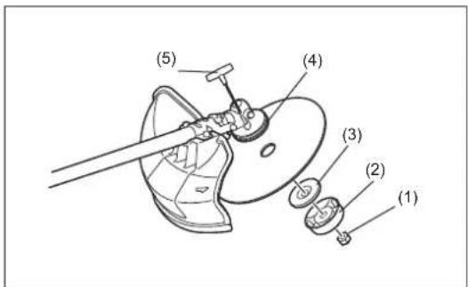
Turn the straight shaft upside down, and you can replace the metal blade or nylon cutting head easily.
- Insert the hex wrench (5) through the hole in the gear case and rotate the receiver washer (4) until it is locked with the hex wrench.
- Loosen the nut (1) (left-hand thread) with the socket wrench and remove the nut (1), cup (2), and clamp washer (3).
text_image
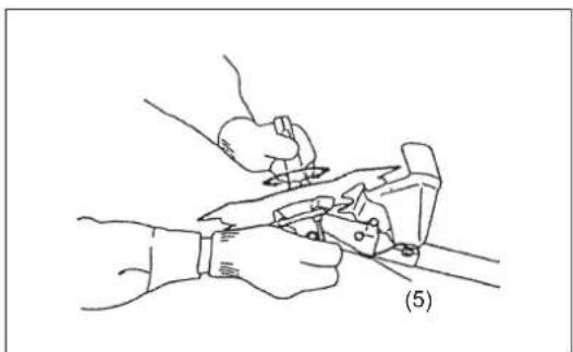
(1) (2) (3) (4) (5)Mounting of metal blade with the hex wrench still in place
- Mount the metal blade onto the shaft so that the guide of the receiver washer (4) fits in the arbor hole in the metal blade. Install the clamp washer (3), cup (2), and secure the metal blade with the nut (1).
[Tightening torque: 20 - 30 N·m]
NOTE:
• Always wear gloves when handling the metal blade.
NOTE:
- The metal blade-fastening nut (with spring washer) is a consumable part. If there appears any wear or deformation on the spring washer, replace the nut.
natural_image
Line drawing of two hands using a tool to adjust or install a mechanical component, labeled (5), with no text or symbols present.Mounting of nylon cutting head
- The clamp washer (3), cup (2), and nut (1) are not necessary for mounting the nylon cutting head. The nylon cutting head should go on top of the receiver washer (4).
- Insert the hex wrench (5) through the hole in the gear case and rotate the receiver washer (4) until it is locked with the hex wrench.
- Then screw the nylon cutting head onto the shaft by turning it counterclockwise.
- Remove the hex wrench.
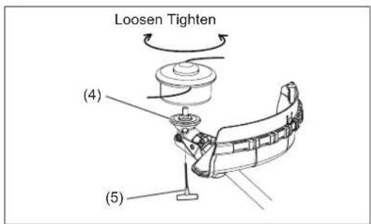
text_image
Loosen Tighten (4) (5)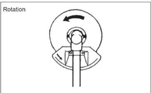
text_image
RotationInspection and refill of engine oil
- Perform the following procedure, with the engine cooled down.
- Assure that the engine is on a flat horizontal surface and confirm if the oil level is between the lower (1) and upper (2) limit of the oil indicator.
- If the oil level is below the lower limit, remove the oil cap and add oil.
- The area surrounding the external marks is transparent, so the amount of oil inside can be checked without having to remove the oil cap. However, if oil pipe becomes extremely dirty, visibility may be lost, and oil level will have to be checked against stepped section on inside of oil pipe.
- You may need to refill oil approximately every 10 operating hours (every 10 refuellings).
If the oil changes in color or mixes with dirt, replace it with new one. (For the interval and method of replacement, refer to P 23.)
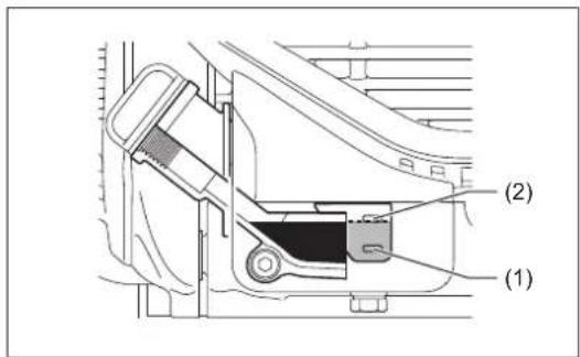
text_image
(1) (2)Recommended oil: SAE 10W-30 oil of API Classification, Class SF or higher (4-stroke engine for automobile)
Oil volume: Approx. 0.10L
NOTE:
- If the engine is not positioned as illustrated on a horizontal surface, an inaccurate indication of oil level may occur and oil may be overfilled. Filling oil above the upper limit may cause oil contamination and/or white smoke.
Replacement of oil: "Oil cap"
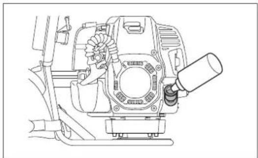
- Remove dust or dirt near the oil refill port, and detach the oil cap.
- Keep the detached oil cap free of sand or dust. Otherwise, any sand or dust adhering to the oil cap may cause irregular oil circulation or wear on the engine parts, which will result in troubles.
(1) Keep the engine level, and detach the oil cap.
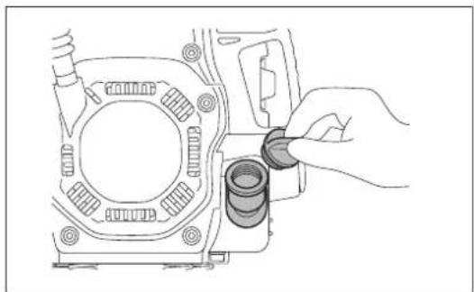
natural_image
Line drawing of a hand inserting a cylindrical component into a mechanical housing (no text or symbols)(2) Fill with oil to upper limit mark. Use oil bottle when filling.
natural_image
Technical line drawing of a mechanical assembly with no visible text or symbols(3) Securely tighten the oil cap. Insufficient tightening may cause oil leakage.
NOTE:
- Do not replace oil with the engine in a tilted position.
- Filling with oil while engine is tilted leads to overfilling which causes oil contamination and/or white smoke.
After refilling oil
- Wipe with a rag any spilled oil immediately.
REFUELLING
Handling of fuel
It is necessary to handle fuel with utmost care. Fuel may contain substances similar to solvents. Refuelling must be performed in a sufficiently ventilated room or in the open air. Never inhale fuel vapor, and keep fuel away from you. If you touch fuel repeatedly or for a long time, the skin becomes dry, which may cause skin disease or allergy. If fuel enters into the eye, clean the eye with fresh water. If your eye remains still irritated, consult your doctor.
Storage period of fuel
Fuel should be used within a period of 4 weeks, even if it is kept in a special container in a well-ventilated and shaded area. Otherwise, fuel may deteriorate in one day.
STORAGE OF MACHINE AND REFILL TANK
- Keep the machine and tank at a cool place free from direct sunshine.
- Never keep the fuel in a car.
Fuel
The engine is a four-stroke engine. Be sure to use an unleaded automobile gasoline 87 or higher octane ((R+M)/2). It may contain no more than 10% alcohol (E-10).
Points for fuel
- Never use a gasoline mixture which contains engine oil. Otherwise, it will cause excessive carbon accumulation or mechanical troubles.
- Use of deteriorated oil will cause irregular start-up.
Refuelling
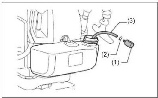
WARNING:
- Shut off the engine before refuelling, keep away from open flames and do not smoke.
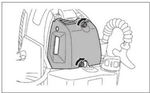
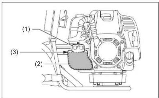
- Loosen the tank cap (1) a little to release the tank pressure.
- Remove the tank cap, and refuel. DO NOT fill fuel more than fuel upper limit (3).
- Wipe the outside of the tank cap to prevent debris from entering into the fuel tank.
• After refuelling, securely tighten the tank cap.
NOTE:
- If there is any flaw or damage on the tank cap, replace it.
- The tank cap wears out in course of time. Replace it every two to three years.
• DO NOT put fuel in the oil fill port.
text_image
(1) (3) (2)CORRECT HANDLING OF MACHINE
WARNING:
- Failure to maintain complete control of the machine at all could result in serious bodily injury or DEATH.
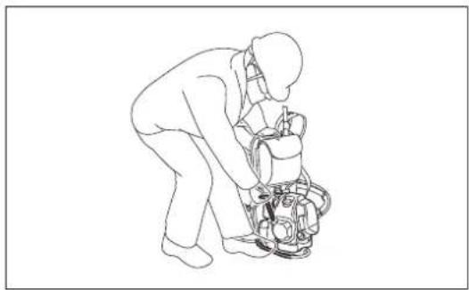
Attachment of harness
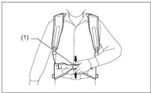
Adjust the harness for shouldering the engine comfortably during operation.
-
Put the harness on your back, and close the buckle (1). To fasten the waist strap, pull the end of the strap (A). To loosen it, pull up the end of the fastener (2) (B).
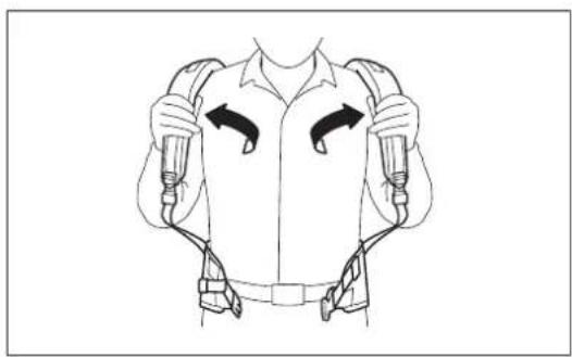
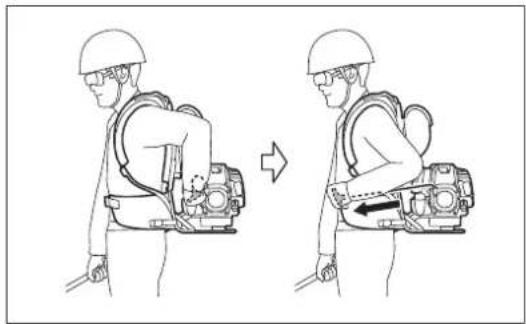
-
Adjust the shoulder strap (3) to a length that is comfortable to work. To fasten the strap, pull the end of the strap. To loosen it, pull up the end of the fastener (4).
-
Adjust the stabilizer strap of the shoulder and hip (5, 6). To fasten the strap, pull the end of the strap. To loosen it, pull up the end of the fastener.
-
Roll redundant straps and fasten them with the loop and hook fastener.
natural_image
Two workers in protective gear using a handheld device, no text or symbols visible
text_image
(1) A B (2)
text_image
(3) (4)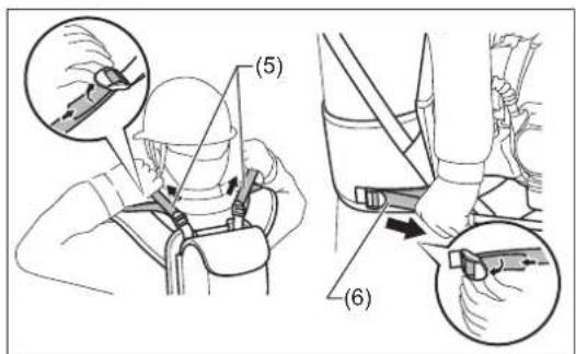
text_image
(5) (6)
text_image
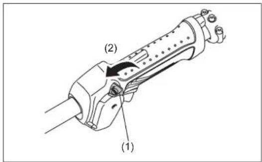
Diagram illustrating the step-by-step assembly of a mechanical clamp mechanism, showing how fastening and turning process from clamping to rolling.Releasing the machine
- To release the machine, squeeze the sides of the buckle (1) and take off the harness.
Be extremely careful to maintain control of the machine at this time. Do not allow the machine to be deflected toward you or anyone in the work vicinity.
text_image
(1)
natural_image
Line drawing of a person wearing a full-body exoskeleton device with two arms and buttons (no text or symbols)HOW TO START AND STOP ENGINE
Observe the applicable accident prevention regulations!
STARTING
Move at least 3 m away from the place of refuelling. Place the unit on the ground taking care that the cutting tool does not come into contact with the ground or any other objects.
A: Cold start
1) Set this machine on a flat space.
2) Set the I-O switch (1) to OPERATION (2).
3) Choke lever
Close the choke lever.
Choke opening:
• Full closing in cold or when the engine is cold.
- Full or half opening if the engine is a bit warm, such as restarting engine just after stopping during warm-up operation.
4) Primer pump
Continue to push the primer pump (3) until fuel comes into the primer pump. (In general, 7 to 10 pushes.) If the primer pump is pushed excessively, an excess of gasoline returns to the fuel tank.
text_image
(1) (2)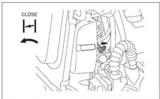
text_image
CLOSE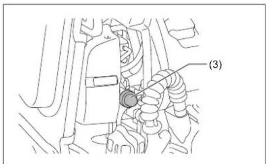
text_image
(3)5) Recoil starter
Make sure you have a firm footing.
Hold the unit with your left hand and press it down firmly.
CAUTION:
- Do not stand or kneel on the throttle cable. The internal wire may be pulled and the cutting tool may start rotating unintentionally. Do not open the throttle.
Pull the starter knob gently until a certain resistance is felt. Then, return the starter knob, and pull it strongly.
Never pull the rope to the full extension. Once the starter knob is pulled, never release your hand immediately. Hold the starter knob until it returns to its original point.
6) Choke lever
Once engine starts, set choke lever to the OPEN position.
- Open the choke lever gradually while checking the engine operation. Be sure to open the choke lever to the full in the end. - In cold or when the engine is cooled down, never open the choke lever suddenly. Otherwise the engine may stop.
7) Warm-up operation
Continue warm-up operation for 2 to 3 minutes.
NOTICE:
- Do not pull the throttle lever unnecessarily while the engine is not running. It may cause fuel leak from the air cleaner. If it happens, wipe leaked fuel off. Also, open the air cleaner cover and clean the element and the air cleaner plate.
natural_image
Line drawing of a person assembling or repairing a mechanical device (no text or symbols)
text_image
OPENNOTE:
- Do not pull the throttle lever unnecessarily when the engine is not running. It may cause flooding of fuel in the engine, and may cause the engine difficult to start up.
- In case of flooding of the fuel, remove the spark plug and pull the starter handle slowly to remove excess fuel. Also, dry the electrode section of the spark plug.
- If the engine fires and stops, or stops soon after starting, return the choke lever to the OPEN position, and pull the starter knob a few times again to start the engine.
- If the choke lever is left in the CLOSE position, and the starter knob merely pulled repeatedly, too much fuel will be sucked in, and the engine will become difficult to start.
- Do not race the engine in warm-up operation unnecessarily.
B: Warm start
1) Keep the choke lever full open.
2) Push the primer pump repeatedly.
3) Keep the throttle lever at the idling position.
4) Pull the starter knob strongly.
You can also restart the engine while carrying the tool on your back.
CAUTION:
- Make sure that the cutting tool is not touching while restarting.
- Do not pull the throttle lever when restarting. Otherwise the cutting tool starts rotating.
natural_image
Illustration of a person in a safety harness performing a right-hand rule, showing body positioning and movement (no text or symbols)Hold the handle with your right hand, and pull the starter knob strongly.
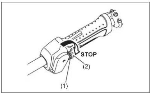
STOPPING
1) Release the throttle lever (2) fully, and when the engine rpm has lowered, set the I-O switch (1) to STOP the engine will now stop.
2) The cutting tool continues to rotate a while after stopping the engine. Wait until it stops completely.
text_image
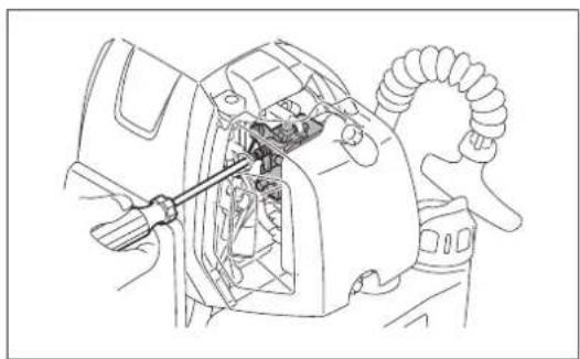
STOP (2) (1)ADJUSTMENT OF IDLE SPEED
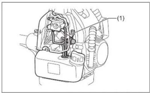
When it is necessary to adjust the idle speed, perform it by the carburetor adjusting screw.
CHECKUP OF IDLE SPEED
- Set the idle speed to 3,000 min ^1 .
If it is necessary to change the idle speed, use a phillips head screw driver on the screw illustrated on the right. - To increase the idle speed, turn the adjusting screw clockwise.
To reduce the idle speed, turn the adjusting screw counterclockwise. - The carburetor is factory adjusted. However, after several use the idle speed need to be re-adjusted.
natural_image
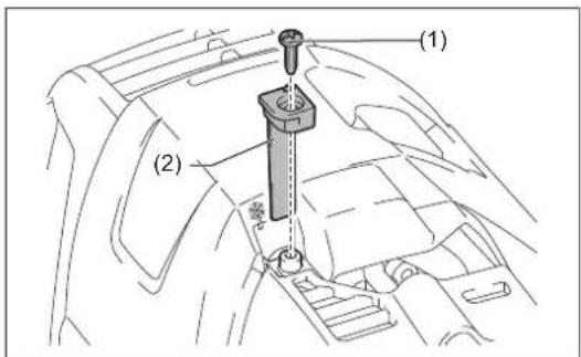
Technical line drawing of a car interior showing engine compartment and handle (no text or symbols)PREVENTION FROM CARBURETOR ICING
CAUTION:
- When environmental temperature is higher than 10^ , always return the shutter to normal (sun mark) setting. Otherwise the engine may be damaged by overheating.
When the environmental temperature is low and humidity is high, water vapor may freeze inside the carburetor and the engine drives unsteadily (carburetor icing). Change the setting of the shutter as follows if necessary.
- Remove the screw (1).
- Change the direction of the shutter (2) as follows:
- Environment temperature is higher than 10^ : Set the shutter in normal position (sun mark).
- Environment temperature is equal or lower than 10^ : Set the shutter in anti-icing position (snow mark).
- Tighten the screw.
text_image
(1) (2)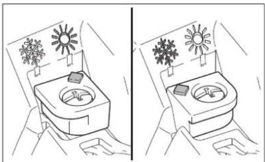
natural_image
Illustration of two hand-drawn scenarios showing a sun and snow-covered appliance with a container, no text or symbols present.RESHARPENING THE CUTTING TOOL

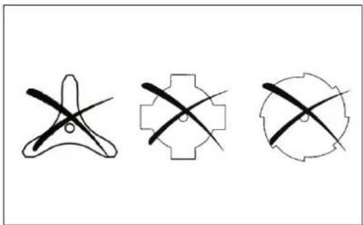
CAUTION:
- The cutting tools shown in the illustration are not to be sharpened. Manual resharpening will result in imbalances of the cutting tool causing vibrations and damage to the equipment.
NOTE:
- To increase the service life of the cutter blade it may be turned over once, until both cutting edges have become blunt.
natural_image
Three abstract geometric diagrams with intersecting lines, no text or symbols presentNYLON CUTTING HEAD
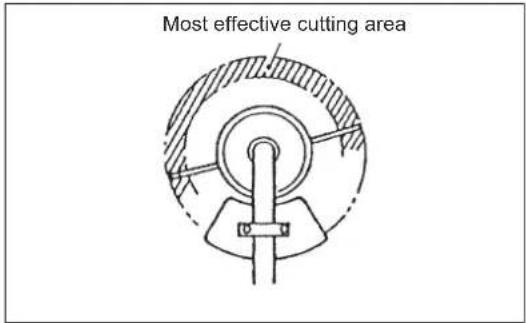
The nylon cutting head is a dual line trimmer head that has bump & feed mechanism.
The nylon cutting head feeds out the nylon cord after tapping the trimmer head on the ground.
Operation
- Increase the nylon cutting head speed to approx. 6,000 min ^1 .
Bump the nylon cutting head lightly on the ground. - The most effective cutting area is shown by the shaded area.
- If the nylon cord does not feed out, rewind/replace the nylon cord by following the procedures described under "Replacing the nylon cord."
text_image
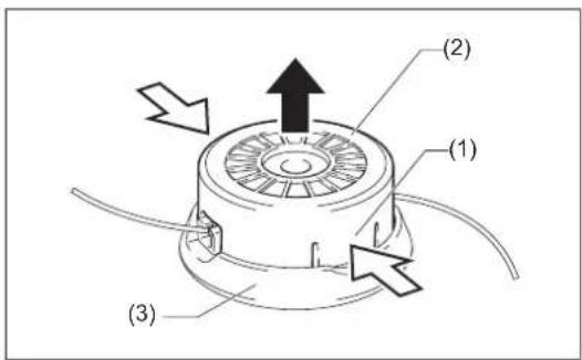
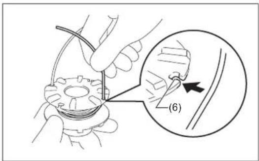
Most effective cutting areaReplacing the nylon cord (BUMP & FEED)
WARNING:
- Make sure that the cover of the nylon cutting head is secured to the housing properly as described below. Failure to properly secure the cover may cause the nylon cutting head to fly apart resulting in serious personal injury.
-
Press the latches (1) on the housing (2) inwards and lift upward to remove the cover (3).
-
Release the nylon cord from the eyelet. And remove the spool (4) from the cover. Discard any of the remaining nylon cord.
-
Hook the middle of the new nylon cord to the notch (5) located at the center of the spool between the 2 channels. One side of the cord should be about 80 mm (3") longer than the other side. Wind both ends firmly around the spool in the direction of arrow mark on the spool.
text_image
(1) (2) (3)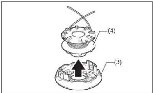
text_image
(4) (3)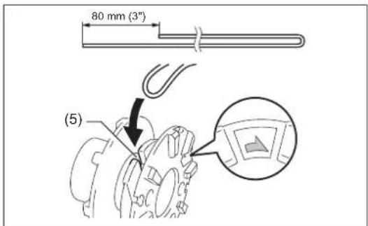
text_image
80 mm (3") (5)-
Wind all but about 100 mm (4") of the cords, leaving the ends temporarily hooked through notches (6).
-
Mount the spool in the cover as holding notches meet the eyelets (7). Unhook the ends of the cord from their temporary position and feed the cords through the eyelets.
-
Align the square slits (8) on the housing with the eyelets (7). Then push the housing firmly onto the cover to secure it. Make sure the latches (1) fully spread in the cover.
text_image
Technical diagram showing a hand holding a mechanical component with an inset close-up highlighting a detail labeled (6)
natural_image
Technical illustration of a mechanical assembly with a component and tool, showing no text or symbols
text_image
(1) (8) (7)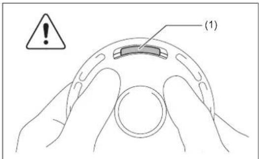
text_image
(1)SERVICING INSTRUCTIONS

CAUTION:
- Before doing any work on the equipment, always stop the engine and pull the plug cap off the spark plug (see “CHECKING THE SPARK PLUG”).
Always wear protective gloves!
To ensure a long service life and to avoid any damage to the equipment, the following servicing operations should be performed at regular intervals.
Daily checkup and maintenance
- Before operation, check the machine for loose screws or missing parts. Pay particular attention to the tightness of the metal blade or nylon cutting head.
- Before operation, always check for clogging of the cooling air passage and the cylinder fins.
Clean them if necessary. - Perform the following work daily after use:
– Clean the equipment externally and inspect for damage.
– Clean the air filter. When working under extremely dusty conditions, clean the filter the several times a day.
- Check the blade or the nylon cutting head for damage and make sure it is firmly mounted.
- Check that there is sufficient difference between idling and engagement speed to ensure that the cutting tool is at a standstill while the engine is idling (if necessary reduce idling speed).
If under idling conditions the tool should still continue to run, consult your nearest Authorized Service Agent.
- Check the functioning of the I-O switch, the lock-off lever and the throttle lever.
REPLACEMENT OF ENGINE OIL
Deteriorated engine oil will shorten the life of the engine. Be sure to check the oil and level regularly.

WARNING: The engine and engine oil is still hot just after stopping engine. Allow sufficient time for the engine and engine oil to cool down. Otherwise a skin burn may result.
NOTE:
- If the oil filled above the limit, it may be contaminated or may catch fire with white smoke. Allow sufficient time after stopping engine for the engine oil to return to the oil tank to ensure accurate reading of the oil level.
Interval of replacement: After first 20 operating hours, followed by every 50 operating hours.
Recommended oil: SAE10W-30 oil of API Classification SF Class or higher (4-stroke engine oil for automobile)
In replacement, perform the following procedure.
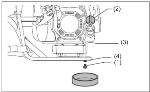
1) Make sure that the fuel tank cap is tightened securely.
2) Place large container (pan, etc.) under drain hole.
3) Remove drain bolt (1) and then remove oil cap (2) to drain out oil from drain hole (3).
At this time, be sure not to lose drain bolt's gasket (4), or get dirty any of the removed components.
4) Once all the oil has been drained, install gasket and drain bolt, and tightly secure drain bolt, so that it will not loosen and cause leaks.
[Tightening torque: 5 N•m]
* Use cloth to fully wipe off any oil attached to bolt and equipment.
text_image
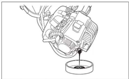
(1) (2) (3) (4)Alternative draining method
Remove oil cap, tilt the equipment toward oil filler hole, and drain out oil.
Collect oil in container.
natural_image
Line drawing of a mechanical component with a pouring liquid into a container (no text or symbols)5) Set the engine level, and gradually fill up to upper limit mark with new oil.
6) After filling, tightly secure oil cap, so that it will not loosen and cause leaks. If oil cap is not tightly secured, it may leak.
POINTS ON OIL
- Never discard replaced engine oil in garbage, earth or sewage ditch. Disposal of oil is regulated by law. In disposal, always follow the relevant laws and regulations. For any points remaining unknown, contact Authorized Service Agent.
- Oil will deteriorate even when it is kept unused. Perform inspection and replacement at regular intervals (replace with new oil every 6 months).
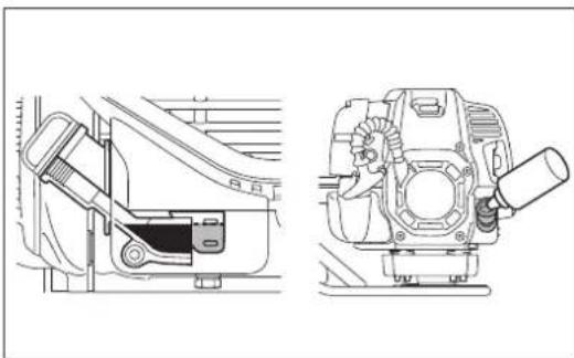
CLEANING OF AIR CLEANER

WARNING: Shut off the engine, keep away from open flames and do not smoke.
Interval of Cleaning and Inspection: Daily (every 10 operating hours)
- Turn the choke lever to the full close side, and keep the carburetor off from dust or dirt.
Removing air cleaner cover
- Loosen two fixing bolts (1).
- Pull and remove the air cleaner cover (2).
Cleaning element
- Remove the elements (3, 4) and tap them to remove dirt.
• For heavy contamination:
1) Remove the element (sponge) (3), immerse it in warm water or in water-diluted neutral detergent, and dry it completely. Do not squeeze or rub it when washing.
2) Clean the element (paper) (4) by tapping it gently. If you can use an air blow gun, blow the compressed air onto the inside of the element (paper). Do not wash the element (paper).
- Before attaching the element (sponge), be sure to dry it completely. Insufficient drying of the element (sponge) may lead to difficult start-up.
- Wipe out oil adhering around the air cleaner cover and separator plate (5) with waste cloth.
Attaching air cleaner cover
- Fit the element (sponge) and element (paper). Insert the element (sponge) all the way into the air cleaner cover.
- Tighten the air cleaner cover with two fixing bolts.
NOTICE:
- Clean the elements several times a day, if excessive dust adheres to it. Dirty elements reduce engine power and make starting engine difficult.
- Remove oil on the elements. If operation continues with the elements remaining not cleared of oil, oil in the air cleaner may fall outside, resulting in contamination of the environment.
- Do not put the elements on the ground or dirty place. Otherwise they pick up dirt or debris and it may damage the engine.
- Never use fuel for cleaning the elements. Fuel may damage them.
natural_image
Technical line drawings of mechanical components, one showing a left-side bracket and the other a side-view view (no text or symbols)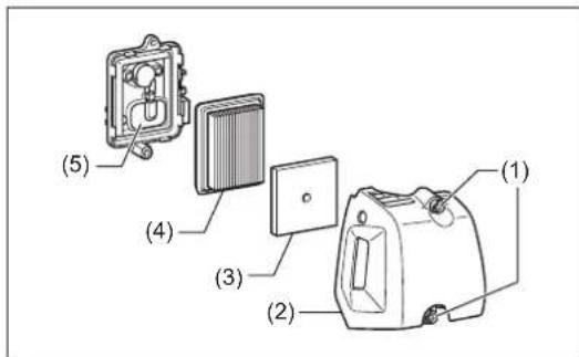
text_image
(1) (2) (3) (4) (5)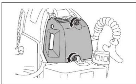
natural_image
Line drawing of a car interior showing a mounted device with airflow indicators (no text or symbols)
text_image
(2) (3)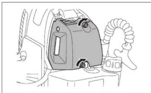
natural_image
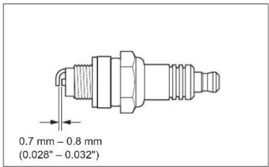
Line drawing of a car interior showing a mounted device with scroll wheel and valve (no text or symbols)CHECKING THE SPARK PLUG
- Only use the supplied universal wrench to remove or to install the spark plug.
- The gap between the two electrodes of the spark plug should be 0.7 – 0.8 mm (0.028" – 0.032"). If the gap is too wide or too narrow, adjust it. If the spark plug is clogged or contaminated, clean it thoroughly or replace it.
Place the plug cap properly as illustrated after checking.
CAUTION:
- Never touch the spark plug connector while the engine is running (danger of high voltage electric shock).
text_image
0.7 mm - 0.8 mm (0.028" - 0.032")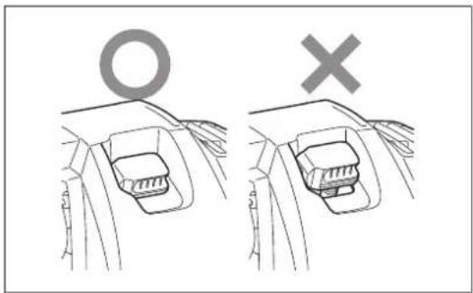
text_image
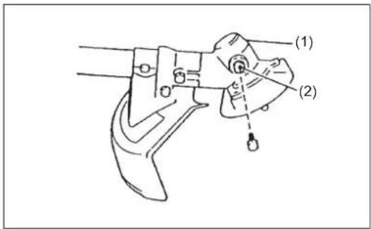
Diagram showing two mechanical components with symbols: a circle labeled 'O' above one and a cross below the other, likely illustrating a mechanical or electrical setup.SUPPLY OF GREASE TO GEAR CASE
- Supply grease (Shell Alvania 2 or equivalent) to the gear case (1) through the grease hole (2) every 25 hours. (Genuine MAKITA grease may be purchased from your MAKITA dealer.)
text_image
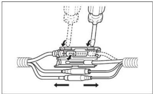
(1) (2)SUPPLY OF GREASE TO THE FLEXIBLE SHAFT
- By performing the steps in "MOUNTING OF FLEXIBLE SHAFT" in reverse, remove the clamps (3 pieces), and disconnect the lead units (2 pieces) and the control cable.
natural_image
Technical diagram of a mechanical assembly with no visible text or symbolsNOTE:
- Use a slotted screwdriver etc. for opening the connector.
- Remove the flexible shaft from the clutch case and the straight shaft. To remove the flexible shaft from the clutch case, pull up the knob and remove it. To remove the flexible shaft from the straight shaft, remove the bolt and remove it.
- Pull out the inner shaft (1) from the flexible liner (2), and apply grease (Shell Alvania 2 or equivalent) (3) on the inner shaft for every 25 hours. (Genuine MAKITA grease may be purchased from your MAKITA dealer.)
- Refer to the steps in "MOUNTING OF FLEXIBLE SHAFT", reassemble the flexible shaft, control cable, lead units (2 pieces), and clamps (3 pieces).
text_image
(2) (1) (3)NOTICE:
- The flexible shaft may be broken if no grease is applied.
- For extending service life of the parts, reinstall each end of the flexible shaft onto the opposite side, i.e. formerly engine side onto the control lever side.
CLEANING OF FUEL FILTER
WARNING: INFLAMMABLES STRICTLY PROHIBITED
Interval of Cleaning and Inspection: Monthly (every 50 operating hours)
Suction head in the fuel tank
Check the fuel filter (1) periodically. To check the fuel filter, follow the steps below:
- Remove the fuel tank cap, drain the fuel to empty the tank. Check the tank inside for any foreign materials. If any, remove them.
- Pull out the suction head by using a wire hook through the tank opening.
-
If the fuel filter clogged slightly, clean it. To clean it, gently shake and tap it in fuel. To avoid damage, do not squeeze or rub it. The fuel used for the cleaning must be disposed in accordance with the method specified by regulations in your country. If the fuel filter became hard or heavily clogged up, replace it.
-
After checking, cleaning or replacing, insert the fuel filter into the fuel pipe (3) and fix it by the hose clamp (2). Push the fuel filter in all the way to the bottom of the fuel tank.
Clogged or damaged fuel filter can cause insufficient fuel supply and reduce engine power. Replace the fuel filter at least quarterly to ensure satisfactory fuel supply to the carburetor.
text_image
(1) (2) (3)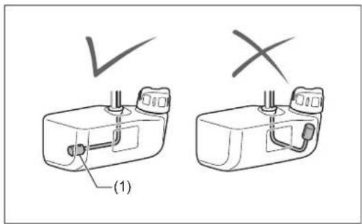
text_image
(1) ✓ ×REPLACEMENT OF FUEL PIPE
CAUTION: INFLAMMABLES STRICTLY PROHIBITED
Interval of Cleaning and Inspection: Daily (every 10 operating hours) Replacement: Annually (every 200 operating hours)
Replace the fuel pipe (1) every year, regardless of operating frequency. Fuel leakage may lead to fire.
If any leakage is detected during inspection, replace the fuel pipe immediately.
text_image
(1)INSPECTION OF BOLTS, NUTS AND SCREWS
- Retighten loose bolts, nuts, etc.
- Check the fuel cap and oil cap for tightness. Check for fuel and oil leakage.
- Replace damaged parts with new ones for safety operation.
CLEANING OF PARTS
• Always keep the engine clean by wiping down with a cloth rag.
- Keep the cylinder fins free of dust or dirt. Dust or dirt adhering to the fins will cause piston seizure.
REPLACEMENT OF GASKETS AND PACKINGS
Replace gaskets and packings if the engine is disassembled.
Any maintenance or adjustment work that is not included and described in this manual is only to be performed by Authorized Service Agents.
STORAGE

WARNING: The engine is still hot just after stopping engine. When draining the fuel, allow sufficient time for the engine to cool down after stopping it. Otherwise a skin burn and/or fire may result.

DANGER: When the machine is kept out of operation for a long time, drain all fuel from the fuel tank and carburetor, and keep it at a dry and clean place.
1) Remove the fuel tank cap, and drain fuel completely.
If there is any foreign matter remaining in the fuel tank, remove it completely.
2) Pull out the fuel filter from the refill port using a wire.
3) Push the primer pump until fuel is drained from there, and drain fuel coming into the fuel tank.
4) Put the filter to the fuel tank, and securely tighten the fuel tank cap.
5) Then, continue to operate the engine until it stops.
- Drain fuel from the fuel tank and carburetor according to the following procedure:
- Remove the spark plug, and drip several drops of engine oil through the spark plug hole.
- Gently pull the starter handle so that engine oil will spread over the engine, and attach the spark plug.
- Attach the cover to the metal blade.
- In general, store the machine as illustrated. Pay full attention how to store the machine to prevent the straight shaft from falling. Otherwise it may result in personal injury.
- Keep the drained fuel in a special container in a well-ventilated shade.
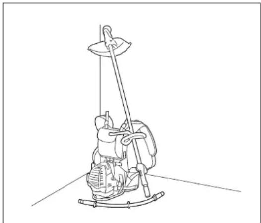
natural_image
Line drawing of a mechanical device with a vertical rod and lever, no text or symbols presentAttention after long-time storage
- Before startup after long-time shutdown, be sure to replace oil (refer to P. 23). Oil will deteriorate while the machine is kept out of operation.
| Operating time Item | Before operation | After refulelling | Daily (10h) | 25h 50h | 200h | Before storage | Corresponding P | ||
| Engine oil | Inspect | ○ | 14 | ||||||
| Replace | ○^*1 | 23 | |||||||
| Tightening parts (bolt, nut) | Inspect | ○ | 26 | ||||||
| Fuel tank | Clean/inspect | ○ | — | ||||||
| Drain fuel | ○^*3 | 27 | |||||||
| Throttle lever Check function | ○ | — | |||||||
| Stop switch Check function | ○ | 23 | |||||||
| Cutting tool Inspect | ○ | ○ | 13 | ||||||
| Idle speed Inspect/adjust | ○ | 20 | |||||||
| Air cleaner Clean | ○ | 24 | |||||||
| Spark plug Inspect | ○ | 25 | |||||||
| Cooling air passage and cylinder fins | Clean/inspect | ○ | 26 | ||||||
| Fuel pipe | Inspect | ○ | 26 | ||||||
| Replace | ○^*2 | 26 | |||||||
| Gear-case grease Refill | ○ | 25 | |||||||
| Flexible shaft | Grease up / changing installation direction | ○ | 25 | ||||||
| Fuel filter Clean/replace | ○ | 26 | |||||||
| Valve clearance (intake valve and exhaust valve) | Inspect/adjust | ○^*2 | — | ||||||
| Carburetor Drain fuel | ○^*3 | 27 |
*1 Perform initial replacement after 20h operation.
*2 For the 200 operating hour inspection, request Authorized Service Agent or a machine shop.
*3 After emptying the fuel tank, continue to run the engine and drain fuel in the carburetor.
TROUBLESHOOTING
Before making a request for repairs, check for trouble by yourself. If any abnormality is found, control your machine according to the description of this manual. Never tamper or dismount any part contrary to the description. For repairs, contact Authorized Service Agent or local dealership.
| State of abnormality Probable cause (malfunction) Remedy | ||
| Engine does not start. | I-O switch is set to STOP. Set the I-O switch to | OPERATION. |
| Failure to operate primer pump. Push 7 to 10 times. | ||
| Low pulling speed of starter rope. Pull strongly. | ||
| Lack of fuel. Feed fuel. | ||
| Clogged fuel filter. Clean. | ||
| Bent fuel tube. Straighten fuel tube. | ||
| Deteriorated fuel. | Deteriorated fuel makes starting more difficult. Replace with new fuel. (Recommended replacement: 1 month) | |
| Excessive suction of fuel. | Set throttle lever from medium speed to high speed, and pull starter handle until engine starts.Once engine starts, cutting tool starts rotating. Pay full attention to cutting tool.If engine will not start still, remove spark plug, dry the electrode, and reassemble them as they originally are. Then, start as specified. | |
| Detached plug cap. Attach securely. | ||
| Contaminated spark plug. Clean. | ||
| Abnormal clearance of spark plug. Adjust clearance. | ||
| Other abnormality of spark plug. Replace. | ||
| Abnormal carburetor. | Make request for inspection and maintenance. | |
| Starter rope cannot be pulled. | Make request for inspection and maintenance. | |
| Abnormal drive system. | Make request for inspection and maintenance. | |
| Engine stops soon.Engine speed does not increase. | Insufficient warm-up. | Perform warm-up operation. |
| Choke lever is set to “CLOSE” although engine is warmed up. | Set to “OPEN”. | |
| Clogged fuel filter. Clean. | ||
| Contaminated or clogged air cleaner. | Clean. | |
| Abnormal carburetor. | Make request for inspection and maintenance. | |
| Abnormal drive system. | Make request for inspection and maintenance. | |
| Metal blade does not rotate.↓Stop engine immediately. | Loosened metal blade-tightening nut. | Tighten securely. |
| Twigs caught by metal blade or dispersion-preventing cover. | Remove foreign matter. | |
| Abnormal drive system. | Make request for inspection and maintenance. | |
| Main unit vibrates abnormally.↓Stop engine immediately. | Broken, bent or worn metal blade. | Replace metal blade. |
| Loosened metal blade-tightening nut. | Tighten securely. | |
| Shifted convex part of metal blade and metal blade support fitting. | Attach securely. | |
| Abnormal drive system. | Make request for inspection and maintenance. | |
| Metal blade does not stop immediately.↓Stop engine immediately. | High idling rotation. | Adjust. |
| Detached throttle wire. | Attach securely. | |
| Abnormal drive system. | Make request for inspection and maintenance. | |
| Engine does not stop.↓Run engine at idling, and set choke lever to “CLOSE”. | Detached connector. | Attach securely. |
| Abnormal electric system. | Make request for inspection and maintenance. | |
Français
(Instructions d'origine)
SOUS TENSION/DÉMARRAGE

HORS TENSION/ARRÊT
CONSIGNES DE SÉCURITÉ
text_image
Warning symbol with exclamation mark inside a triangle
natural_image
Black-and-white illustration of wine bottles and a pen with a crossed arrow, no text or symbols present

(3)


(5)

(6)
natural_image
Line drawing of a person operating a lawn mower in grass (no text or symbols)
natural_image
Line drawing of a person wearing a full-body protective gear with hoses and straps (no text or symbols)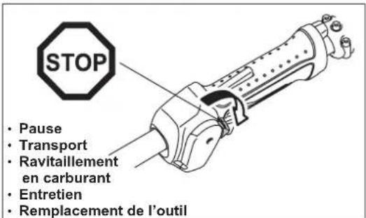
natural_image
Line drawing of a helicopter with three separate aircraft flying nearby (no text or symbols)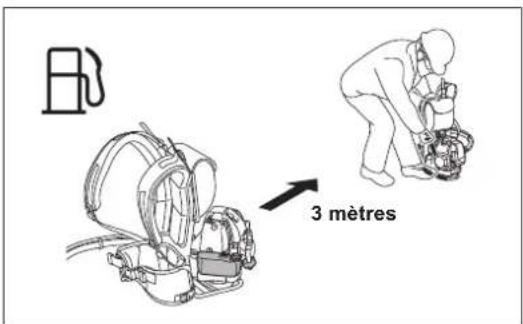
text_image
3 mètresMode d'emploi
text_image
Warning sign depicting a person using a tool to avoid accidents, with symbols indicating exposure and damage.natural_image
Line drawing of a person using a handheld metal detector on a grassy field (no text or symbols)text_image
Illustration showing a person using a power tool with crossed lines and a campfire, surrounded by grass and symbols.text_image
Technical diagram of a mechanical device with numbered parts and an inset showing a component labeled (12) and (7).text_image
Technical diagram showing mechanical assembly with labeled components and a triangular measurement setupMONTAGE DE L'ARBRE FLEXIBLE
text_image
(8) (7) (6)natural_image
Technical line drawing of a mechanical component with labeled parts (11), showing internal structure and arrows indicating movement or force (no text or symbols beyond label)MONTAGE DE LA LAME MÉTALLIQUE OU DE LA TÊTE À FIL DE NYLON
natural_image
Line drawing of two hands using pliers to handle a piece, labeled (5), with no text or symbols present.
text_image
Desserrer Serrer (4) (5)natural_image
Line drawing of a hand inserting a cylindrical component into a mechanical housing (no text or symbols)natural_image
Technical line drawing of a mechanical assembly with no visible text or symbolsnatural_image
Two identical line drawings of a person wearing safety gear, one holding a long tool and the other extending a cable or cable (no text or symbols)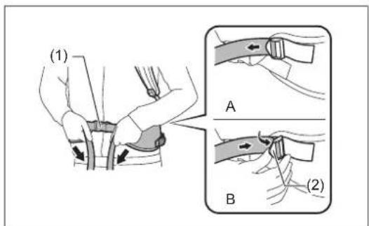
text_image
(1) A B (2)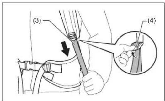
text_image
(3) (4)
text_image
(5) (6)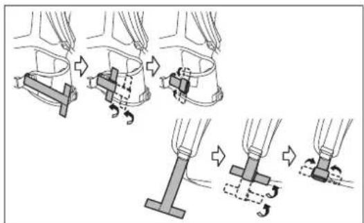
text_image
Diagram illustrating the step-by-step assembly of a mechanical clamp mechanism, showing how fastening and turning process are performed.natural_image
Line drawing of a person wearing a full-body exoskeleton device with two arms and buttons (no text or symbols)COMMENT DÉMARRER ET ARRÊTER LE MOTEUR
natural_image
Line drawing of a person operating a mechanical device (no text or symbols)natural_image
Illustration of two workers in safety gear performing a task, showing a change from one to the other (no text or symbols present)ARRÊT
text_image
STOP (2) (1)RÉGLAGE DU RALENTI
natural_image
Technical line drawing of a car interior showing engine compartment and handle (no text or symbols)PRÉVENTION DU GIVRAGE DU CARBURATEUR
ATTENTION :
natural_image
Two-panel line drawing showing a hand holding a box with sun icons above and a second panel showing a tray with items, no text or symbols present.RÉAFFÛTAGE DE L'OUTIL DE COUPE
ATTENTION :
natural_image
Three abstract geometric diagrams with intersecting lines and shapes, no text or symbols presentnatural_image
Technical line drawing of a mechanical component with concentric rings and a central shaft (no text or symbols)Remplacement du fil de nylon (AVANCEMENT PAR SECOUSSE)
AVERTISSEMENT :
natural_image
Technical illustration of a mechanical assembly with a component and tool, showing no text or symbols
text_image
(1) (8) (7)
text_image
(1)INSTRUCTIONS D'ENTRETIEN
ATTENTION :
natural_image
Line drawing of a mechanical component pouring liquid into a circular container (no text or symbols)natural_image
Technical line drawings of mechanical components, showing front and side views (no text or symbols)NETTOYAGE DU FILTRE À AIR

natural_image
Line drawing of a car interior showing a mounted device with a hose and fan (no text or symbols)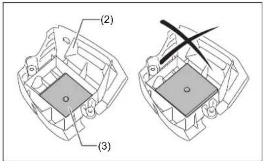
text_image
(2) (3)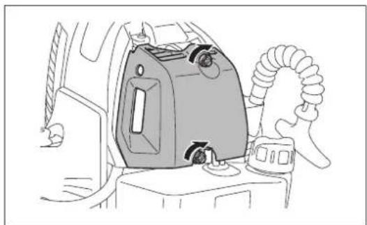
natural_image
Line drawing of a car interior showing a mounted device with a coiled hose and handle (no text or symbols)VÉRIFICATION DE LA BOUGIE
text_image
Diagram showing two mechanical components with symbols: a circle labeled 'O' and a cross symbol, likely illustrating a mechanical or electrical assembly.GRAISSAGE DU CARTER D'ENGRENAGES
natural_image
Technical diagram of a mechanical assembly with no visible text or symbolsNOTE :
natural_image
Line drawing of a mechanical device with a vertical rod and lever, no text or symbols presenttext_image
Warning symbol with exclamation mark inside a triangle
natural_image
Black-and-white illustration of wine bottles and a pen with a crossed arrow, no text or symbols present

(3)


(5)

(6)
natural_image
Line drawing of a person working with a mechanical device outdoors (no text or symbols)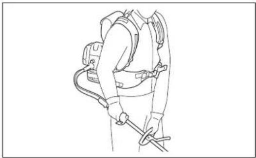
natural_image
Line drawing of a person wearing a full-body protective gear with straps and a tool (no text or symbols)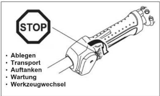
natural_image
Line drawing of a helicopter with three propeller aircraft flying nearby (no text or symbols)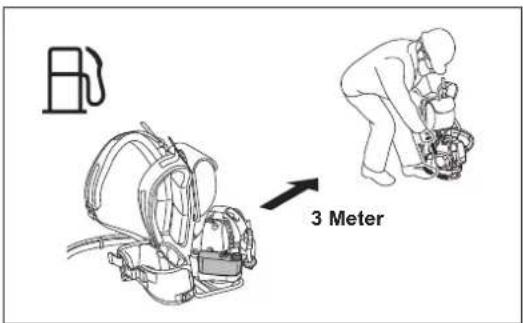
text_image
Warning sign depicting a person using a tool to avoid accidents, with arrows indicating direction and symbols for visibility.natural_image
Line drawing of a person using a metal detector on a tripod (no text or symbols)text_image
Illustration showing a person using a power tool with crossed-out tools, alongside a campfire and grass symbols.MONTIEREN DES HANDGRIFFS
⚠ VORSICHT:
text_image
Technical diagram showing mechanical assembly with labeled components and alignment linesMONTIEREN DER BIEGEWELLE
text_image
(6) (7) (8)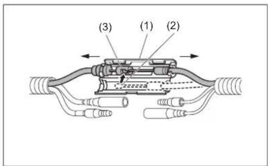
text_image
(3) (1) (2)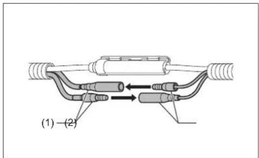
text_image
(1) - (2)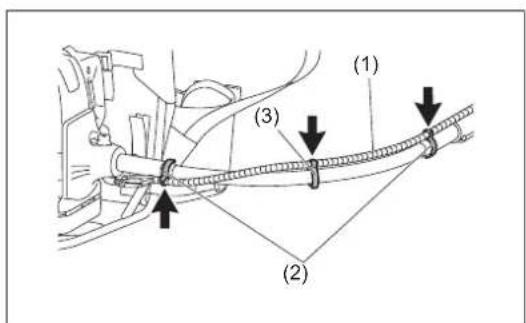
text_image
(1) (2) (3)MONTIEREN DER SCHUTZHAUBE
natural_image
Technical line drawing of a mechanical component with labeled parts (11), showing internal structure and arrows indicating movement or force (no text or symbols beyond label)MONTIEREN DES METALLBLATTS / NYLONFADENKOPFS
natural_image
Line drawing of two hands using pliers to handle a small object, labeled (5), with no text or symbols present.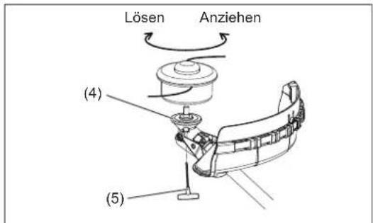
natural_image
Line drawing of a mechanical component with a hand inserting a cylindrical part (no text or symbols)natural_image
Technical line drawing of a mechanical assembly with no visible text or symbolsnatural_image
Two workers in protective gear using a handheld device, no text or symbols visibletext_image
Diagram illustrating the step-by-step assembly of a mechanical clamp mechanism, showing how fastening and turning process are performed.natural_image
Line drawing of a person wearing a full-body exoskeleton device with two arms and buttons (no text or symbols)natural_image
Line drawing of a person assembling or repairing a mechanical device (no text or symbols)
text_image
OPENHINWEIS:
natural_image
Illustration of two workers in hard hats performing a task, showing a change from one to the other (no text or symbols present)ABSTELLEN
text_image
STOP (2) (1)natural_image
Technical line drawing of a mechanical assembly with no visible text or symbolsnatural_image
Two-panel line drawing showing a hand holding a box with sun icons above and a second panel showing a tray with items, no text or symbols present.natural_image
Three abstract geometric diagrams with intersecting lines and shapes, no text or symbols presentnatural_image
Technical line drawing of a mechanical component with concentric rings and a central shaft (no text or symbols)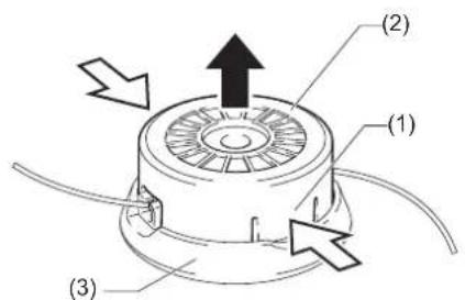
text_image
(1) (2) (3)
text_image
(4) (3)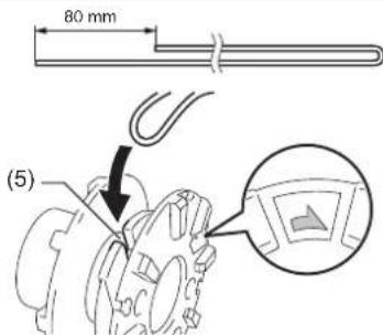
text_image
80 mm (5)text_image
Technical diagram showing a hand holding a mechanical component with an inset magnified view labeled (6)
natural_image
Technical illustration of a mechanical component with a coiled cable and a hand holding a tool, showing a step (no text or symbols)
text_image
(1) (8) (7)
text_image
(1)WARTUNGSANWEISUNGEN
⚠ VORSICHT:
Alternative Ablassmethode
natural_image
Diagram of a car engine with a piston pouring liquid into a cylinder (no text or labels)natural_image
Technical line drawings of mechanical components, showing front and side views (no text or symbols)
text_image
(1) (2) (3) (4) (5)
natural_image
Line drawing of a car interior with a gas stove and hose (no text or symbols)
text_image
(2) (3)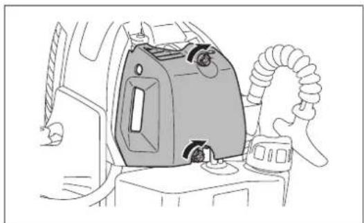
natural_image
Line drawing of a car interior with a mounted air conditioner unit and coiled hose (no text or symbols)ÜBERPRÜFEN DER ZÜNDKERZE
text_image
Diagram showing two mechanical components with symbols: a circle labeled 'O' and a cross symbol, likely illustrating a mechanical or electrical setup.ABSCHMIEREN DES GETRIEBEGEHÄUSES
natural_image
Technical diagram of a mechanical assembly with no visible text or symbolsHINWEIS:
natural_image
Line drawing of a mechanical device with a lever and base, no text or symbols presenttext_image
Warning symbol with exclamation mark inside a triangle
natural_image
Black-and-white illustration of wine bottles and a pen with a crossed arrow, no text or symbols present

(3)


(5)

(6)
text_image
Figura schematica 360° 15 metri 15m (50 m)natural_image
Line drawing of a person operating a lawn mower in grass, with no text or symbols present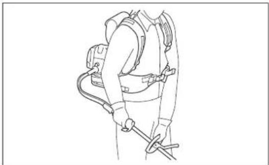
natural_image
Line drawing of a person wearing a full-body protective gear with hoses and straps (no text or symbols)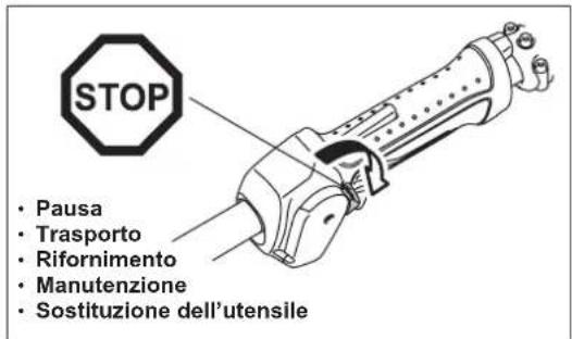
natural_image
Line drawing of a helicopter with three separate aircraft below (no text or symbols)
text_image
3 metritext_image
Warning sign depicting a person using a tool to avoid accidents, with arrows indicating direction and symbols for 'no accident' and 'no damage'.natural_image
Line drawing of a person using a metal detector on a grassy field (no text or symbols)text_image
Illustration showing a person using a power tool with crossed-out tools, alongside a campfire and grass symbols.text_image
Technical diagram of a mechanical device with numbered parts and an inset showing a component labeled (12) and (7).text_image
Technical diagram showing mechanical assembly with labeled components and a triangular measurement setupMONTAGGIO DELL'ALBERO FLESSIBILE
text_image
(8) (7) (6)natural_image
Technical line drawing of a mechanical component with directional arrows indicating movement or force (no text or symbols present)MONTAGGIO DELLA LAMA IN METALLO O DELLA TESTINA DA TAGLIO IN NYLO
natural_image
Line drawing of two hands using pliers to handle a small object, labeled (5), with no text or symbols present.natural_image
Line drawing of a hand inserting a cylindrical component into a mechanical housing (no text or symbols)natural_image
Technical line drawing of a mechanical assembly with no visible text or symbolsnatural_image
Two workers in protective gear using a handheld device, no text or symbols visible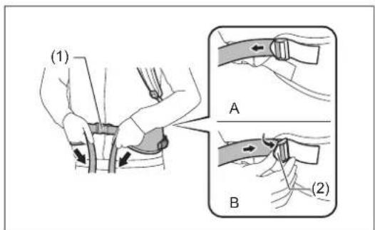
text_image
(1) A B (2)
text_image
(3) (4)
text_image
(5) (6)
text_image
Diagram illustrating the step-by-step assembly of a mechanical clamp mechanism, showing how fastening and turning a component with rotational motion.natural_image
Line drawing of a person wearing a full-body exoskeleton device with two arms and buttons (no text or symbols)MODO DI AVVIARE E DI ARRESTARE IL MOTORE
natural_image
Line drawing of a person assembling or repairing a mechanical device (no text or symbols)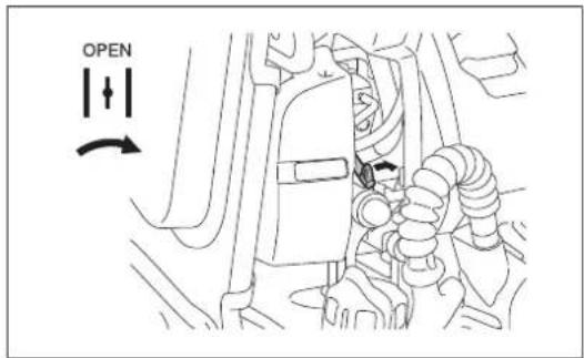
text_image
OPENNOTA:
natural_image
Illustration of two workers in hard hats performing a task, showing a change in the movement (no text or symbols present)ARRESTO
text_image
STOP (2) (1)REGOLAZIONE DELLA VELOCITÀ DEL MINIMO
natural_image
Technical line drawing of a mechanical assembly with no visible text or symbolsnatural_image
Illustration of a hand holding a small appliance with sun icons above, showing two views (no text or symbols)AFFILATURA DELL'ATTREZZO DA TAGLIO
ATTENZIONE:
natural_image
Three abstract geometric diagrams with intersecting lines and shapes, no text or symbols presentTESTINA DI TAGLIO IN NYLON
natural_image
Line drawing of a mechanical component pouring liquid into a container (no text or symbols)natural_image
Technical line drawing of a mechanical device showing front and side views (no text or symbols)
text_image
(1) (2) (3) (4) (5)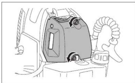
natural_image
Line drawing of a car interior showing a gas stove with airflow direction indicators (no text or symbols)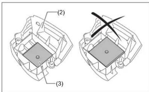
text_image
(2) (3)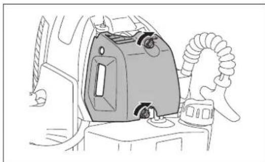
natural_image
Line drawing of a car interior showing a gas vent and attached vehicle (no text or symbols)CONTROLLO DELLA CANDELA
text_image
Diagram showing two mechanical components with symbols: a circle labeled 'O' and a cross symbol, likely illustrating a mechanical or electrical assembly.LUBRIFICAZIONE DELLA SCATOLA DEGLI INGRANAGGI
natural_image
Technical diagram of a mechanical assembly with no visible text or symbolsNOTA:
natural_image
Line drawing of a mechanical device with a lever and base, no text or symbols presenttext_image
Warning symbol with exclamation mark inside a triangle
natural_image
Illustration of wine bottles and a black-and-white striped ribbon, no text or symbols present

(3)


(5)

(6)
text_image
Schematische voorstelling 360° 15 meter 15m (50 m)natural_image
Line drawing of a person working with a mechanical device outdoors (no text or symbols)
natural_image
Line drawing of a person wearing a full-body harness and safety harness (no text or symbols)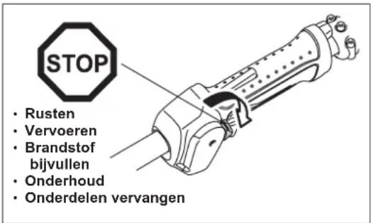
natural_image
Line drawing of a helicopter with two separate aircraft flying nearby (no text or symbols)
text_image
3 meterGebruiksmethode
text_image
Warning sign depicting a person using a tool to avoid accidents, with symbols indicating exposure and noise.Let op: Terugslag
text_image
12 2natural_image
Line drawing of a person using a metal detector on a grassy field (no text or symbols)text_image
Illustration showing a person using a power tool with crossed-out tools, alongside a campfire and grass symbols.DE HANDGREEP MONTEREN
LET OP:
text_image
Technical diagram showing mechanical assembly with labeled components and a triangular measurement setupDE FLEXIBELE SCHACHT MONTEREN
De flexibele schacht monteren
text_image
(8) (7) (6)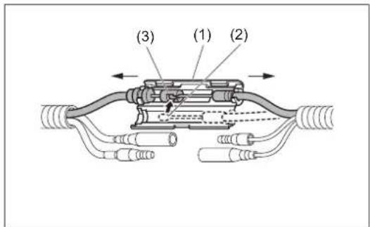
text_image
(3) (1) (2)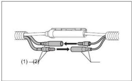
text_image
(1) - (2)
text_image
(1) (2) (3)DE BESCHERMKAP MONTEREN
natural_image
Technical line drawing of a mechanical component with labeled parts (11), showing internal structure and arrows indicating movement or force (no text or symbols beyond label)HET METALEN SNIJBLAD OF DE NYLONDRAAD-SNIJKOP MONTEREN
natural_image
Line drawing of two hands using pliers to cut a tool, labeled (5), with no text or symbols present.natural_image
Line drawing of a mechanical component with a hand inserting a cylindrical part (no text or symbols)natural_image
Technical line drawing of a mechanical assembly with no visible text or symbolsnatural_image
Two identical line drawings of a person wearing protective gear, one extending to reach a tool, the other holding a tool (no text or symbols present)text_image
Diagram illustrating the step-by-step assembly of a mechanical clamp mechanism, showing how fastening and turning process are performed.natural_image
Line drawing of a person wearing a full-body exoskeleton device with two arms and shoulder straps (no text or symbols)natural_image
Line drawing of a person assembling or repairing a mechanical device (no text or symbols)
text_image
OPENOPMERKING:
natural_image
Illustration of two workers in hard hats performing a task, showing a change from one to the other (no text or symbols present)STOPPEN
text_image
STOP (2) (1)HET STATIONAIR TOERENTAL INSTELLEN
natural_image
Technical line drawing of a mechanical assembly with no visible text or symbolsIJSVORMING IN CARBURATEUR VOORKOMEN

LET OP:
natural_image
Two-panel line drawing showing a hand holding a small container with sun icons above and a second with a bowl containing food items, no text or symbols present.HET SNIJGARNITUUR SLIJPEN

LET OP:
natural_image
Three abstract geometric diagrams with intersecting lines, no text or symbols present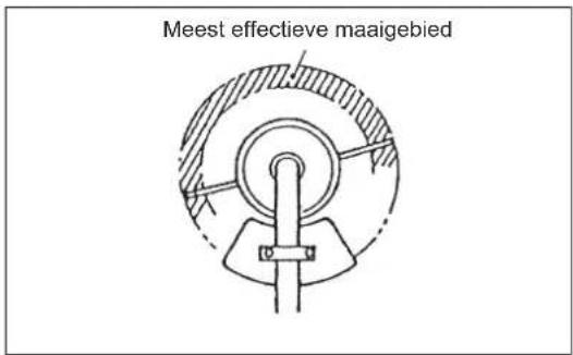
text_image
Meest effective maaigebied
text_image
(1) (2) (3)
text_image
(4) (3)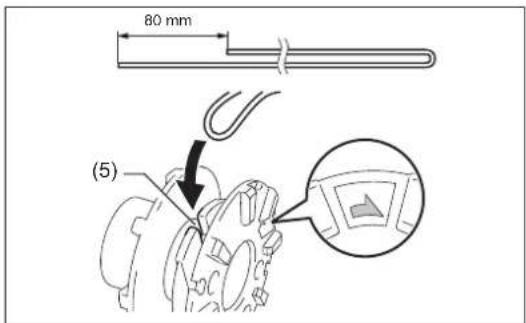
text_image
80 mm (5)text_image
Technical diagram showing a hand holding a mechanical component with an inset close-up highlighting a detail labeled (6)
natural_image
Technical illustration of a mechanical component with a coiled cable and a hand holding a tool, showing a step (no text or symbols)
text_image
(1) (8) (7)
text_image
(1)ONDERHOUDSINSTRUCTIES

LET OP:
natural_image
Diagram of a car engine component being poured into a container (no text or symbols)natural_image
Technical line drawings of mechanical components, showing front and side views (no text or symbols)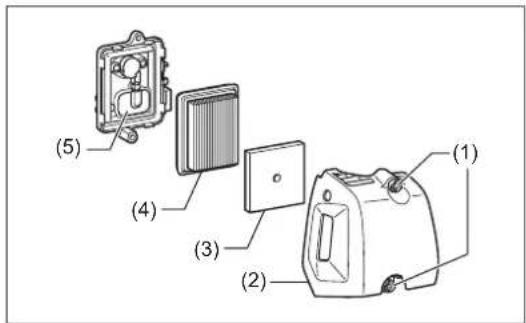
text_image
(1) (2) (3) (4) (5)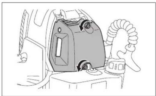
natural_image
Line drawing of a car interior showing a mounted device with airflow indicators (no text or symbols)
text_image
(2) (3)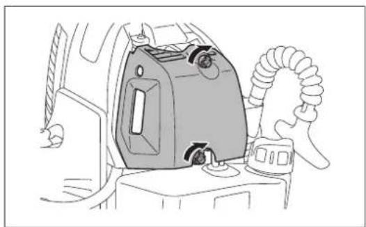
natural_image
Line drawing of a car interior with a mounted air conditioner unit and coiled hose (no text or symbols)DE BOUGIE CONTROLEREN
text_image
Diagram showing two mechanical components with symbols: a circle labeled 'O' and a cross symbol, likely illustrating a mechanical or electrical setup.HET TANDWIELHUIS SMEREN
natural_image
Technical diagram of a mechanical assembly with no visible text or symbolsOPMERKING:
Zuigkop in brandstoftank
natural_image
Line drawing of a mechanical device with a lever and base, no text or symbols presenttext_image
Warning symbol image with exclamation mark inside a triangle
natural_image
Black-and-white illustration of wine bottles and a pen with a crossed arrow, no text or symbols present

(3)


(5)

(6)
text_image
Figura de diagrama 360° 15 metros 15m (50 m)natural_image
Line drawing of a person operating a lawn mower in grass (no text or symbols)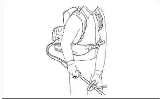
natural_image
Line drawing of a person wearing a full-body protective gear with attached equipment (no text or symbols)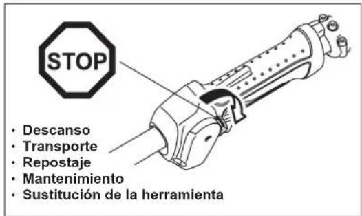
natural_image
Line drawing of a helicopter with three propeller aircraft flying nearby (no text or symbols)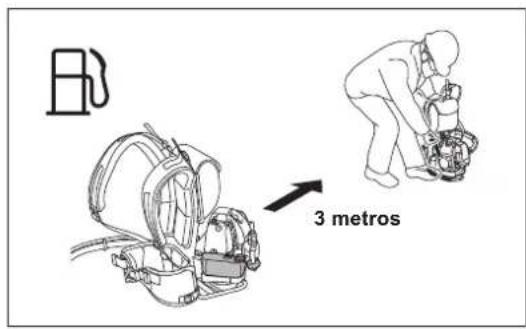
text_image
3 metrosMétodo de trabajo
text_image
Warning sign depicting a person using a tool to avoid accidents, with symbols indicating exposure and noise.Precaución: Contragolpe
text_image
12 2
Figura de diagrama

text_image
12 11 2 9 3 8 6 5
Figura de diagrama

natural_image
Line drawing of a person using a metal detector on a grassy field (no text or symbols)text_image
Illustration showing a person using a power tool with crossed lines and a campfire, surrounded by grass and symbols.text_image
Technical diagram of a mechanical device with numbered parts and an inset showing a component labeled (12) and (7).text_image
Technical diagram showing mechanical assembly with labeled components and a triangular measurement setupMONTAJE DEL EJE FLEXIBLE
text_image
(8) (7) (6)natural_image
Technical line drawing of a mechanical component with labeled parts (11), showing internal structure and arrows indicating movement or force (no text or symbols beyond label)MONTAJE DE LA CUCHILLA DE METAL O DEL CABEZAL DE CORTE DE NYLON
natural_image
Line drawing of two hands using pliers to cut a tool, labeled (5), with no text or symbols present.natural_image
Line drawing of a hand inserting a coin into a mechanical component (no text or symbols)natural_image
Technical line drawing of a mechanical assembly (no text or symbols)natural_image
Two workers in safety gear using a portable device, one holding a hose and the other extending a hose (no text or symbols visible)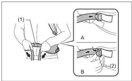
text_image
(1) A B (2)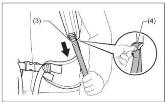
text_image
(3) (4)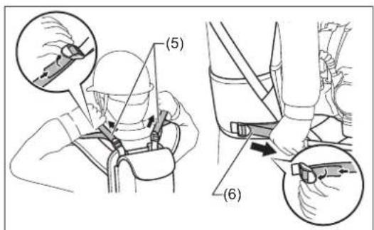
text_image
(5) (6)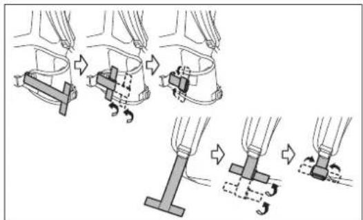
natural_image
Illustration of mechanical fasteners and clamps in action, showing step-by-step assembly (no text or symbols)natural_image
Line drawing of a person wearing a full-body exoskeleton device with two arms and buttons (no text or symbols)CÓMO PONER EN MARCHA Y PARAR EL MOTOR
natural_image
Line drawing of a person assembling or repairing a mechanical device (no text or symbols)
text_image
OPENNOTA:
natural_image
Illustration of two workers in hard hats performing a task, showing a change from one to the other (no text or symbols present)PARADA
text_image
STOP (2) (1)natural_image
Technical line drawing of a mechanical assembly with no visible text or symbolsnatural_image
Illustration of a hand holding a small appliance with sun icons above, showing two views (no text or symbols)natural_image
Three abstract geometric diagrams with intersecting lines and shapes, no text or symbols presentCABEZAL DE CORTE DE NYLON
text_image
Technical diagram showing a hand holding a mechanical component with an inset magnified view labeled (6)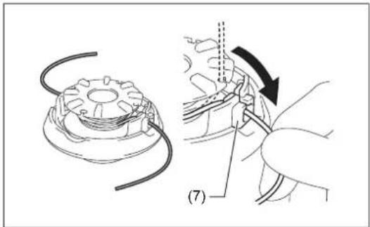
natural_image
Technical illustration of a mechanical component with a coiled cable and a hand holding a tool, showing a step (no text or symbols)
text_image
(1) (8) (7)
text_image
(1)INSTRUCCIONES DE SERVICIO
PRECAUCIÓN:
natural_image
Diagram of a mechanical component pouring liquid into a container (no text or symbols)natural_image
Technical line drawing of a mechanical device showing front and side views (no text or symbols)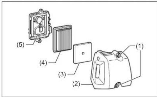
text_image
(1) (2) (3) (4) (5)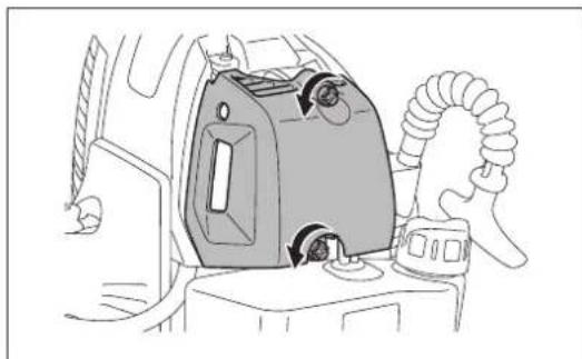
natural_image
Line drawing of a car interior showing a mounted device with airflow arrows (no text or symbols)
text_image
(2) (3)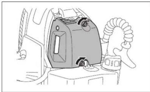
natural_image
Line drawing of a car interior showing a mounted air conditioner unit with hoses and a handle (no text or symbols)text_image
Diagram showing two mechanical components with symbols: a circle labeled 'O' and a cross symbol, likely illustrating a mechanical or electrical assembly.SUMINISTRO DE GRASA A LA CAJA DE ENGRANAJES
natural_image
Technical diagram of a mechanical assembly with no visible text or symbolsNOTA:
natural_image
Line drawing of a mechanical device with a vertical rod and lever, no text or symbols presenttext_image
Warning symbol with exclamation mark inside a triangle
natural_image
Illustration of wine bottles and a pen crossed over, with scattered pills below (no text or symbols)


(5)

(6)
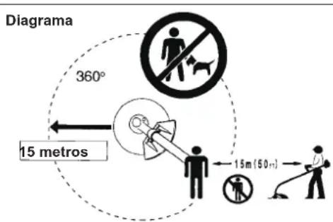
text_image
Diagrama 360° 15 metros 15m (50 m)natural_image
Line drawing of a person operating a lawn mower in grass (no text or symbols)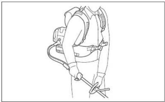
natural_image
Line drawing of a person wearing a full-body medical harness and safety harness (no text or symbols)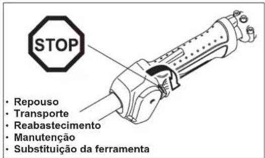
natural_image
Line drawing of a helicopter with three additional propeller aircraft nearby (no text or symbols)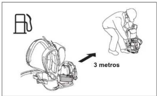
text_image
3 metros- Aplique a secção entre as 8 e as 11 horas;
text_image
Warning sign depicting a person using a tool to avoid accidents, with symbols indicating exposure and damage.Precaução: Recuo

text_image
12 2
Diagrama

text_image
12 11 2 9 3 8 6 5
Diagrama

natural_image
Line drawing of a person using a metal detector on a field (no text or symbols)Nunca alise ou solde ferramentas de corte danificadas.
text_image
Illustration showing a person using a power tool with crossed-out tools, alongside a campfire and grass symbols.text_image
Technical diagram of a mechanical device with numbered parts and an inset showing a component labeled (12) and (7).natural_image
Mechanical assembly diagram showing a lever mechanism and tool path (no text or symbols)MONTAGEM DO EIXO FLEXÍVEL
text_image
(6) (7) (8)
text_image
(3) (1) (2)
text_image
(1) - (2)
text_image
(1) (2) (3)MONTAGEM DO PROTECTOR
natural_image
Technical line drawing of a mechanical component with labeled parts (11), showing internal structure and arrows indicating movement or force (no text or symbols beyond label)natural_image
Line drawing of two hands using pliers to handle a tool, labeled (5), with no text or symbols present.natural_image
Line drawing of a hand inserting a cylindrical component into a mechanical housing (no text or symbols)natural_image
Technical line drawing of a mechanical assembly with no visible text or symbolsnatural_image
Two workers in protective gear using a handheld device, no text or symbols visibletext_image
Diagram illustrating the step-by-step assembly of a mechanical clamp mechanism, showing how fastening and turning a component with rotational motion.Libertar a máquina
natural_image
Line drawing of a person wearing a vest with two arms, showing shoulder and chest movement arrows (no text or symbols)COMO ARRANCAR E PARAR O MOTOR
natural_image
Line drawing of a person assembling or repairing a mechanical device (no text or symbols)
text_image
OPENNOTA:
natural_image
Illustration of a person in safety gear performing a task with an instructor, showing two sequential poses (no text or symbols)PARAR
text_image
STOP (2) (1)natural_image
Technical line drawing of a mechanical assembly with no visible text or symbolsnatural_image
Two-panel line drawing showing a hand holding a box with sun icons above and a second panel showing a tray with items, no text or symbols present.VOLTAR A AFIAR A FERRAMENTA DE CORTE
PRECAUÇÃO:
natural_image
Three abstract geometric diagrams with intersecting lines and shapes, no text or symbols presentCABEÇA DE CORTE EM NYLON
natural_image
Technical illustration of a mechanical component with a coiled cable and a hand holding a tool, showing a step (no text or symbols)
text_image
(1) (8) (7)
text_image
(1)INSTRUÇÕES DE SERVIÇO
PRECAUÇÃO:
natural_image
Diagram of a car engine with a piston pouring liquid into a cylinder (no text or labels)natural_image
Technical line drawings of mechanical components, showing front and side views (no text or symbols)
text_image
(1) (2) (3) (4) (5)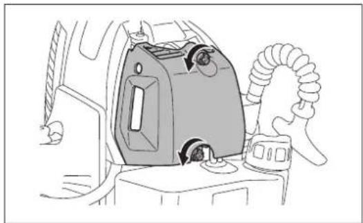
natural_image
Line drawing of a car interior showing a mounted device with airflow arrows (no text or symbols)
text_image
(2) (3)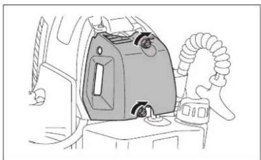
natural_image
Line drawing of a car interior showing a mounted device with hoses and a handle (no text or symbols)VERIFICAR A VELA DE IGNICÃO
text_image
Diagram showing two mechanical components with symbols: a circle labeled 'O' and a cross symbol, likely illustrating a mechanical or electrical assembly.natural_image
Technical diagram of a mechanical assembly with no visible text or symbolsNOTA:
natural_image
Line drawing of a mechanical device with a vertical rod and lever, no text or symbols presenttext_image
Warning symbol image with exclamation mark inside a triangle
natural_image
Black-and-white illustration of wine bottles and a pen with a crossed arrow, no text or symbols present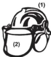


(5)

(6)

text_image
Skematisk figur 360° 15 meter 15m (50 m)natural_image
Line drawing of a person operating a lawn mower in grass (no text or symbols)
natural_image
Line drawing of a person wearing a full-body protective gear with hoses and backpacks (no text or symbols)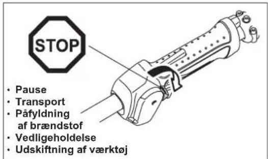
natural_image
Line drawing of a helicopter with three additional helicopters flying nearby (no text or symbols)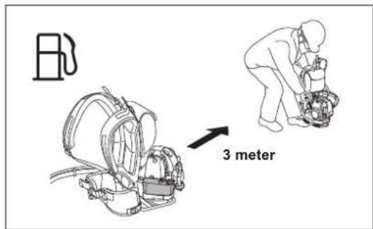
text_image
3 meterBetjeningsmetode
text_image
Warning sign depicting a person using a tool to avoid accidents, with symbols indicating exposure and damage.natural_image
Line drawing of a person using a handheld metal detector on a grassy field (no text or symbols)text_image
Illustration showing a person using a power tool with crossed lines and a campfire, surrounded by grass and symbols.text_image
Technical diagram of a mechanical device with numbered parts and an inset showing a component labeled (12) and (7).natural_image
Technical diagram showing mechanical assembly with tool, pulley, and angle measurement (no text or symbols)MONTERING AF DET FLEKSIBLE SKAFT
text_image
(8) (7) (6)
text_image
(3) (1) (2)
text_image
(1) - (2)
text_image
(1) (2) (3)MONTERING AF BESKYTTELSESKAERM
natural_image
Technical line drawing of a mechanical component with labeled parts (11), showing internal structure and arrows indicating movement or force (no text or symbols beyond label)MONTERING AF METALKLINGE ELLER NYLONTRIMMERHOVED
Sørg for at anvende ægte MAKITA-metalklinger eller nylontrimmerhoved.
natural_image
Line drawing of two hands using pliers to cut a tool, labeled (5), with no text or symbols present.Montering af nylontrimmerhoved
text_image
Løsn Stram (4) (5)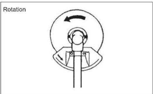
text_image
RotationINDEN ANVENDELSE
natural_image
Line drawing of a mechanical component with a hand inserting a cylindrical part (no text or symbols)natural_image
Technical line drawing of a mechanical assembly with no visible text or symbolsnatural_image
Two workers in safety gear using a handheld device, one with a hose and the other with a hose (no text or symbols visible)
text_image
(1) A B (2)
text_image
(3) (4)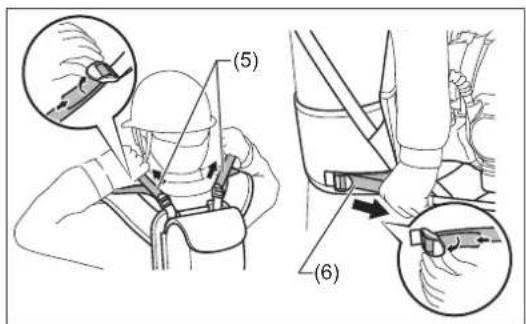
text_image
(5) (6)
text_image
Diagram illustrating the step-by-step assembly of a mechanical clamp mechanism, showing how fastening and turning process are performed.natural_image
Line drawing of a person wearing a vest with two exoskeleton straps, showing shoulder joint movement arrows (no text or symbols)HVORDAN MOTOREN STARTES OG STOPPES
natural_image
Line drawing of a person assembling or repairing a mechanical device (no text or symbols)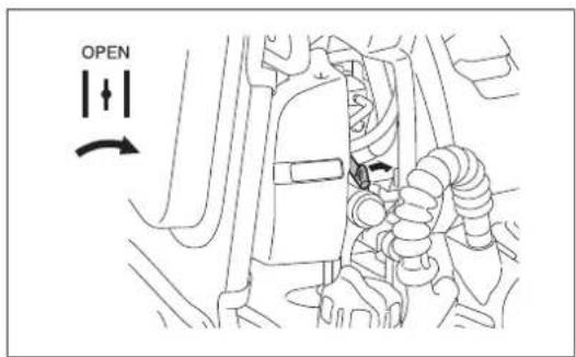
text_image
OPENBEMÆRK:
natural_image
Illustration of two workers in safety gear performing a task, showing head and torso positioning (no text or symbols)text_image
STOP (2) (1)JUSTERING AF TOMGANGSHASTIGHED
natural_image
Technical line drawing of a mechanical assembly with no visible text or symbolsFORHINDRING AF TILISNING AF KARBURATOR
⚠ FORSIGTIG:
natural_image
Two-panel line drawing showing a hand holding a device with sun icons above and a second panel showing a device with snowflakes and a small object on the screen (no text or symbols)SLIBNING AF SKÆREVÆRKT∅JET
FORSIGTIG:
natural_image
Three abstract geometric diagrams with intersecting lines, no text or symbols presentNYLONTRIMMERHOVED
text_image
Technical diagram showing a hand holding a mechanical component with an inset magnified view highlighting a detail labeled (6)
natural_image
Technical illustration of a mechanical assembly with a component and tool, showing no text or symbols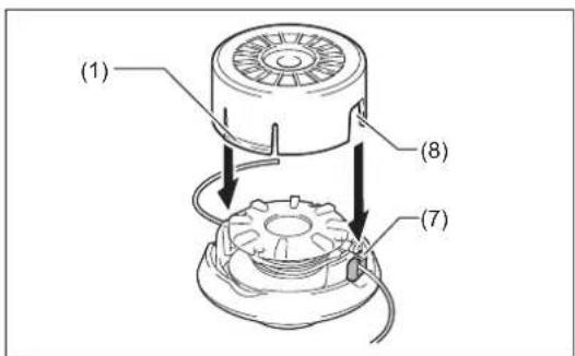
text_image
(1) (8) (7)
text_image
(1)SERVICERINGSINSTRUKTIONER
⚠️ FORSIGTIG:
natural_image
Diagram of a mechanical component being poured into a container labeled 'ref.51' (no text or symbols on the diagram itself)natural_image
Technical line drawings of mechanical components, showing front and side views (no text or symbols)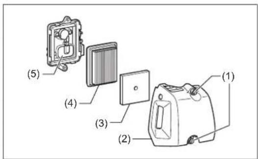
text_image
(1) (2) (3) (4) (5)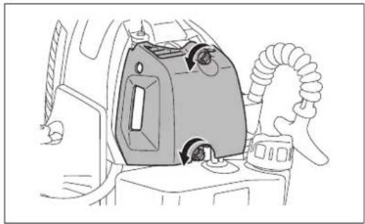
natural_image
Line drawing of a car interior with a gas stove and hose (no text or symbols)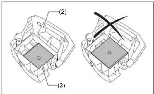
text_image
(2) (3)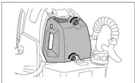
natural_image
Line drawing of a car interior with a portable air conditioner unit and coiled hose (no text or symbols)KONTROL AF TÆNDR∅RET
text_image
Diagram showing two mechanical components with symbols: a circle labeled 'O' and a cross symbol, likely illustrating a mechanical or electrical assembly.TILF∅RSEL AF SM∅REMIDDEL TIL GEARKASSEN
natural_image
Technical diagram of a mechanical assembly with no visible text or symbolsBEMAERK:
natural_image
Line drawing of a mechanical device with a vertical rod and lever, no text or symbols presenttext_image
Warning symbol with exclamation mark inside a triangle
natural_image
Illustration of wine bottles and a pen crossed over, with scattered pills below (no text or symbols)

(3)


(5)

(6)

natural_image
Line drawing of a person operating a lawn mower in grass, with no text or symbols present
natural_image
Line drawing of a person wearing a full-body protective gear with attached equipment (no text or symbols)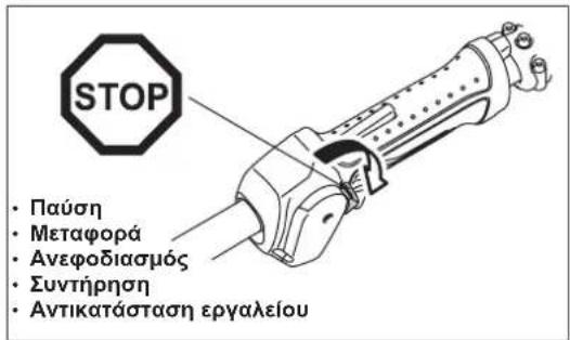
natural_image
Line drawing of a helicopter with three separate aircraft shown in separate views (no text or symbols)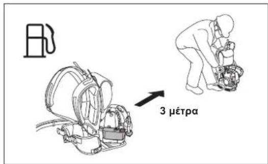
text_image
3 μέτραΜέθοδος λειτουργίας
text_image
Warning sign depicting a person using a tool to avoid accidents, with symbols indicating exposure and damage.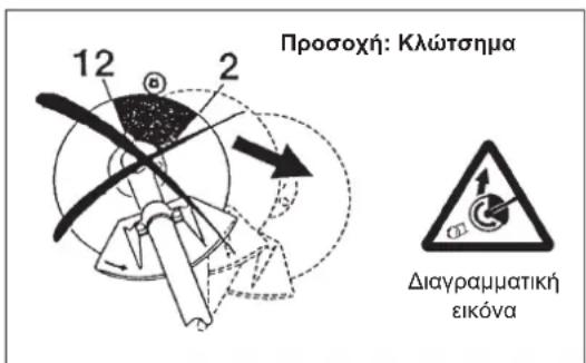
natural_image
Line drawing of a person using a metal detector on a tripod (no text or symbols)text_image
Illustration showing a person using a power tool with crossed lines and a campfire, surrounded by grass and symbols.text_image
Technical diagram showing mechanical assembly with labeled components and alignment linestext_image
(8) (7) (6)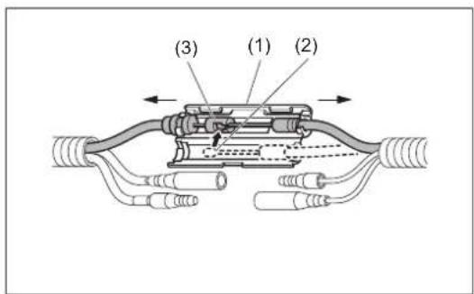
text_image
(3) (1) (2)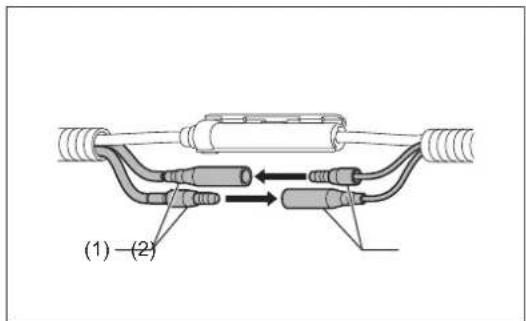
text_image
(1) - (2)
text_image
(1) (2) (3)natural_image
Technical line drawing of a mechanical component with directional arrows indicating movement (no text or symbols)natural_image
Line drawing of two hands using a tool on a mechanical component, labeled (5), with no text or symbols present.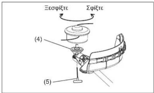
natural_image
Line drawing of a mechanical component being inserted into a housing (no text or symbols)natural_image
Technical line drawing of a mechanical assembly with no visible text or symbolsnatural_image
Two identical line drawings of a person wearing protective gear, one spraying water with a hose and the other holding a hose (no text or symbols)text_image
Diagram illustrating the step-by-step assembly of a mechanical clamp mechanism, showing how fastening and turning process are performed.natural_image
Line drawing of a person wearing a vest with two arms, showing shoulder and chest movement arrows (no text or symbols)natural_image
Line drawing of a person assembling or repairing a mechanical device (no text or symbols)
text_image
OPENΠΑΡΑΤΗΡΗΣΗ:
natural_image
Illustration of two workers in hard hats performing a task, showing a change from one to the other (no text or symbols present)text_image
STOP (2) (1)natural_image
Technical line drawing of a mechanical assembly with no visible text or symbolsnatural_image
Illustration of two hand-drawn scenarios showing a device with sun icons above its screen and a second device with snow flowers on its side (no text or symbols)natural_image
Three abstract geometric diagrams with intersecting lines, no text or symbols presentnatural_image
Technical line drawing of a mechanical component with concentric rings and a central shaft (no text or symbols)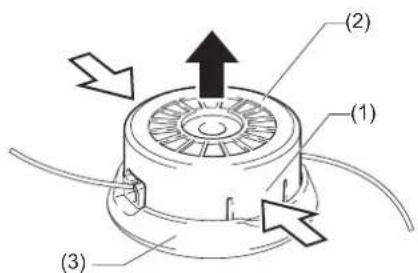
text_image
(1) (2) (3)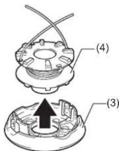
text_image
(4) (3)
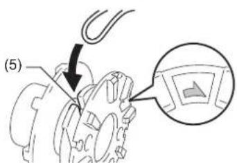
text_image
(5)text_image
Technical diagram showing a hand holding a mechanical component with an inset close-up highlighting a detail labeled (6)
natural_image
Technical illustration of a mechanical assembly with a component and tool, showing no text or symbols
text_image
(1) (8) (7)
text_image
(1)ΟΔΗΓΙΕΣ ΣΕΡΒΙΣ
⚠️ ΠΡΟΣΟΧΗ:
natural_image
Line drawing of a mechanical component pouring liquid into a container (no text or symbols)natural_image
Technical line drawings of mechanical components, showing front and side views (no text or symbols)
text_image
(1) (2) (3) (4) (5)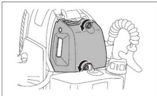
natural_image
Line drawing of a car interior showing a mounted device with a coiled hose and valve (no text or symbols)
text_image
(2) (3)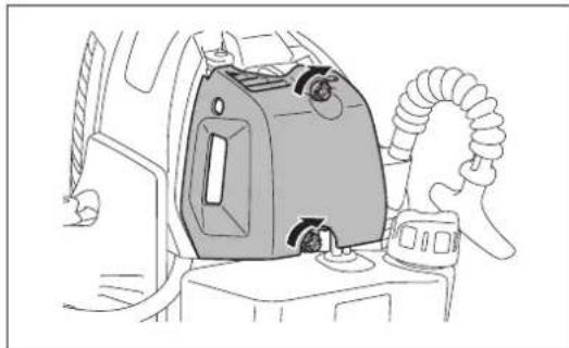
natural_image
Line drawing of a car interior showing a gas vent and hose assembly (no text or symbols)ΕΛΕΓΧΟΣ ΤΟΥ ΜΠΟΥΖΙ
text_image
Diagram showing two mechanical components with symbols: a circle labeled 'O' and a cross symbol, likely illustrating a mechanical or electrical assembly.natural_image
Technical diagram of a mechanical assembly with no visible text or symbolsΠΑΡΑΤΗΡΗΣΗ:
natural_image
Line drawing of a mechanical device with a vertical rod and lever, no text or symbols presenttext_image
Warning symbol with exclamation mark inside a triangle
natural_image
Illustration of wine bottles and a pen crossed over, with scattered pills below (no text or symbols)

(3)


(5)

(6)
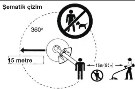
text_image
Şematik çizim 360° 15 metre 15m (50 m)natural_image
Line drawing of a person operating a lawn mower in a field (no text or symbols)
natural_image
Line drawing of a person wearing a full-body protective gear with hoses and straps (no text or symbols)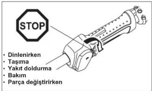
natural_image
Line drawing of a helicopter with three additional aircraft flying nearby (no text or symbols)
text_image
3 metreÇalıştırma yöntemi
text_image
Warning sign depicting a person using a tool to avoid accidents, with symbols indicating exposure and noise.Dikkat: Geri tepme

text_image
12 2
Şematik çizim

text_image
12 11 2 9 8 3 6 5
Şematik çizim

natural_image
Line drawing of a person using a handheld metal detector on a grassy field (no text or symbols)text_image
Illustration showing a person using a power tool with crossed-out tools, alongside a campfire and grass symbols.text_image
Technical diagram showing mechanical assembly with labeled components and a triangular measurement setupESNEK \$AFTIN TAKILMASI
text_image
(8) (7) (6)natural_image
Technical line drawing of a mechanical component with labeled parts (11), showing internal structure and arrows indicating movement or force (no text or symbols beyond label)METAL BIÇAĞIN VEYA MİSİNALI KESİM BAŞLIĞININ TAKILMASI
natural_image
Line drawing of two hands using pliers to handle a small object, labeled (5), with no text or symbols present.natural_image
Line drawing of a mechanical component with a hand inserting a cylindrical part (no text or symbols)natural_image
Technical line drawing of a mechanical assembly with no visible text or symbolsnatural_image
Two identical line drawings of a person wearing protective gear, one spraying water with a hose and the other holding a hose (no text or symbols)text_image
Diagram illustrating the step-by-step assembly of a mechanical clamp mechanism, showing how fastening and turning process are performed.natural_image
Line drawing of a person wearing a vest with two arms, showing shoulder and chest movement arrows (no text or symbols)MOTORU ÇALIŞTIRMA VE DURDURMA
natural_image
Line drawing of a person assembling or repairing a mechanical device (no text or symbols)
text_image
OPENNOT:
natural_image
Illustration of two workers in safety gear performing a task, showing a change from one to the other (no text or symbols present)text_image
STOP (2) (1)RÖLANTİ HIZININ AYARLANMASI
natural_image
Technical line drawing of a car interior showing engine compartment and handle (no text or symbols)KARBÜRATÖR BUZLANMASININ ÖNLENMESİ

DIKKAT:
natural_image
Two-panel line drawing showing hands holding a small appliance with sun icons above and a second device with a tray, no text or symbols present.KESİCİ PARÇANIN BİLENMESİ

DİKKAT:
natural_image
Three abstract geometric diagrams with intersecting lines and shapes, no text or symbols present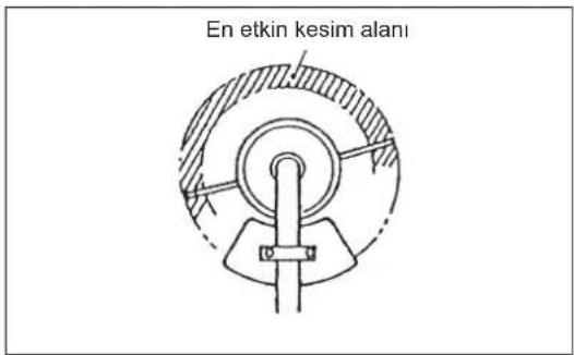
natural_image
Technical illustration of a mechanical component being adjusted, showing a clamping tool interacting with a motor (no text or symbols present)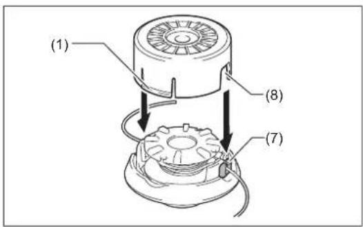
text_image
(1) (8) (7)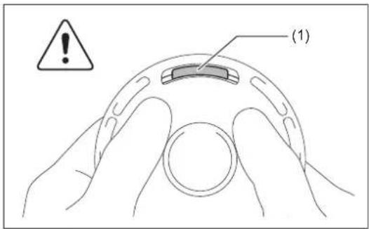
text_image
(1)SERVİS TALİMATLARI

DIKKAT:
natural_image
Line drawing of a car engine component being poured into a container (no text or symbols)natural_image
Technical line drawings of mechanical components, showing front and side views (no text or symbols)HAVA TEMİZLEYİCİSİNİN TEMİZLENMESI

natural_image
Line drawing of a car interior with a portable air conditioner unit and a hose (no text or symbols)
text_image
(2) (3)