
S45MY2E5A - Air-conditioner PANASONIC - Free user manual and instructions
Find the device manual for free S45MY2E5A PANASONIC in PDF.
User questions about S45MY2E5A PANASONIC
0 question about this device. Answer the ones you know or ask your own.
Ask a new question about this device
Download the instructions for your Air-conditioner in PDF format for free! Find your manual S45MY2E5A - PANASONIC and take your electronic device back in hand. On this page are published all the documents necessary for the use of your device. S45MY2E5A by PANASONIC.
USER MANUAL S45MY2E5A PANASONIC
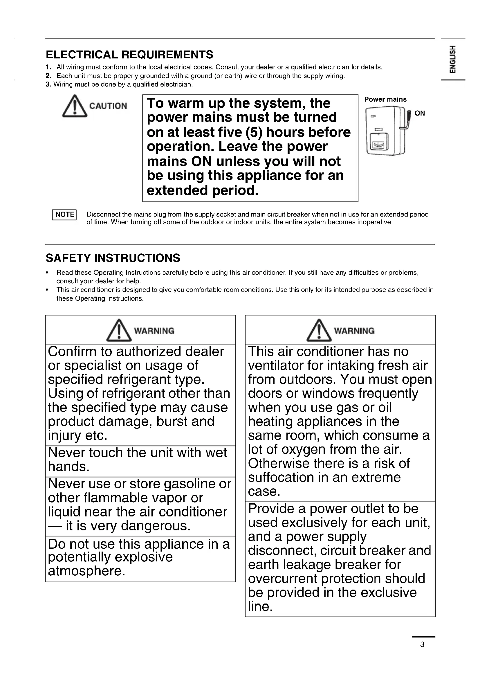
* Shows K2 type (Wall Mounted)
Panasonic®
Operating Instructions Air Conditioner
Model No.
Indoor Units
Wall Mounted
(K2 type)
S-15MK2E5A
S-22MK2E5A
S-28MK2E5A
S-36MK2E5A
Indoor Units
4-Way Cassette
60x60 (Y2 type)
S-15MY2E5A
S-22MY2E5A
S-28MY2E5A
S-36MY2E5A
S-45MY2E5A
S-56MY2E5A
Outdoor Units
mini
(LE1 type)
U-4LE1E5
U-5LE1E5
U-6LE1E5
U-4LE1E8
U-5LE1E8
U-6LE1E8
2WAY
(ME1 type)
U-8ME1E81
U-10ME1E81
U-12ME1E81
U-14ME1E81
U-16ME1E81
U-18ME1E81
U-20ME1E81
3WAY
(MF2 type)
U-8MF2E8
U-10MF2E8
U-12MF2E8
U-14MF2E8
U-16MF2E8


ENGLISH
2~15
Before operating the unit, read these operating instructions thoroughly and keep them for future reference.
FRANÇAIS
16 29
PAGE PRODUCT INFORMATION 2
SAFETY PRECAUTIONS. 2
INSTALLATION LOCATION. 2
ELECTRICAL REQUIREMENTS 3
SAFETY INSTRUCTIONS 3
INFORMATION. 6
OPERATION 7
ADJUSTING AIRFLOW DIRECTION. 9
ADJUSTING AIRFLOW DIRECTION FOR MULTIPLE INDOOR UNITS USING SINGLE REMOTE CONTROLLER (WIRED) 11
SPECIAL REMARKS 12
CARE AND CLEANING 12
TROUBLESHOOTING 14
CHECKBEFORE REQUIRING SERVICES. 15
TIPS FOR ENERGY SAVING 15
SPECIFICATIONS 172
PRODUCT INFORMATION
If you have problems or questions concerning your Air Conditioner, you will need the following information. Model and serial numbers are on the nameplate on the bottom of the cabinet.
Model No. Serial No.
Date of purchase
Dealer's address
Phone number
SAFETY PRECAUTIONS
The following symbols used in this manual, alert you to potentially dangerous conditions to users, service personnel or the appliance:

WARNING

CAUTION
This symbol refers to a hazard or unsafe practice which can result in severe personal injury or death.
This symbol refers to a hazard or unsafe practice which can result in personal injury or product or property damage.
INSTALLATION LOCATION
- We recommend that this air conditioner be installed properly by qualified installation technicians in accordance with the Installation Instructions provided with the unit.
- Before installation, check that the voltage of the electric supply in your home or office is the same as the voltage shown on the nameplate.

WARNING
- Do not install this air conditioner where there are fumes or flammable gases, or in an extremely humid space such as a greenhouse.
- Do not install the air conditioner where excessively high heat-generating objects are placed.
Avoid: To protect the air conditioner from heavy corrosion, avoid installing the outdoor unit where salty sea water can splash directly onto it or in sulphurous air near a spa.
ELECTRICAL REQUIREMENTS
- All wiring must conform to the local electrical codes. Consult your dealer or a qualified electrician for details.
- Each unit must be properly grounded with a ground (or earth) wire or through the supply wiring.
- Wiring must be done by a qualified electrician.

CAUTION
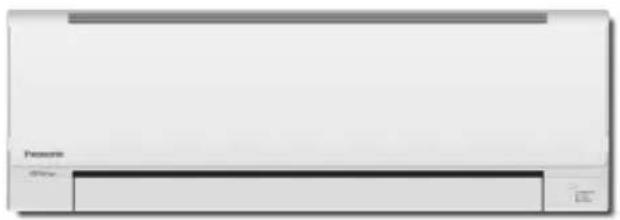
To warm up the system, the power mains must be turned on at least five (5) hours before operation. Leave the power mains ON unless you will not be using this appliance for an extended period.
Power mains
NOTE
Disconnect the mains plug from the supply socket and main circuit breaker when not in use for an extended period of time. When turning off some of the outdoor or indoor units, the entire system becomes inoperative.
SAFETY INSTRUCTIONS
- Read these Operating Instructions carefully before using this air conditioner. If you still have any difficulties or problems, consult your dealer for help.
This air conditioner is designed to give you comfortable room conditions. Use this only for its intended purpose as described in these Operating Instructions.

WARNING
Confirm to authorized dealer or specialist on usage of specified refrigerant type. Using of refrigerant other than the specified type may cause product damage, burst and injury etc.
Never touch the unit with wet hands.
Never use or store gasoline or other flammable vapor or liquid near the air conditioner — it is very dangerous.
Do not use this appliance in a potentially explosive atmosphere.

WARNING
This air conditioner has no ventilator for intaking fresh air from outdoors. You must open doors or windows frequently when you use gas or oil heating appliances in the same room, which consume a lot of oxygen from the air. Otherwise there is a risk of suffocation in an extreme case.
Provide a power outlet to be used exclusively for each unit, and a power supply disconnect, circuit breaker and earth leakage breaker for overcurrent protection should be provided in the exclusive line.
| WARNING |
| Provide a power outlet exclusively for each unit, and full disconnection means having a contact separation in all poles must be incorporated in the fixed wiring in accordance with the wiring rules. |
| To prevent possible hazards from insulation failure, the unit must be grounded. |
| Do not clean inside the indoor and outdoor units by users. Engage authorized dealer or specialist for cleaning. |
| In case of malfunction of this appliance, do not repair by yourself. Contact to the sales dealer or service dealer for a repair. |
| Refrigerant gas leakage may cause fire. |
| For safety, be sure to turn the air conditioner off and also to disconnect the power before cleaning or servicing. |
| Pull off the power plug from a receptacle, or switch off the breaker, or switch off the power disconnecting mean to isolate the air conditioner from the main power supply in case of emergency. |
| WARNING |
| Do not insert your fingers or other objects into the air conditioner indoor or outdoor unit, rotating parts may cause injury. |
| Do not use modified cord, joint cord, extension cord or unspecified cord to prevent overheating and fire. |
| Stop using the product when any abnormality/failure occurs and disconnect the power plug or turn off the power switch and breaker. (Risk of smoke/fire/electric shock) Examples of abnormality/failure • The ELCB trips frequently. • Burning smell is observed. • Abnormal noise or vibration of the unit is observed. • Water leaks from the indoor unit. • Power cord or plug becomes abnormally hot. • Fan speed cannot be controlled. • The unit stops running immediately even if it is switched on for operation. • The fan does not stop even if the operation is stopped. Contact immediately your local dealer for maintenance/ repair. |

CAUTION
This appliance is intended to be used by expert or trained users in shops, in light industry and on farms, or for commercial use by lay persons.
Do not turn the air conditioner on and off from the power mains switch. Use the ON/OFF operation button.
Do not stick anything into the air outlet of the outdoor unit. This is dangerous because the fan is rotating at high speed.
Do not touch the air inlet or the sharp aluminum fins of the outdoor unit. You may get injured.
Keep the fire alarm and the air outlet at least 1.5m away from the unit.

CAUTION
This appliance can be used by children aged from 8 years and above and persons with reduced physical, sensory or mental capabilities or lack of experience and knowledge if they have been given supervision or instruction concerning use of the appliance in a safe way and understand the hazards involved.
Do not cool or heat the room too much if babies or invalids are present.
Do not stick any object into the FAN CASE.
You may be injured and the unit may be damaged.
Do not sit or step on the unit. You may fall down accidentally.


- The compressor may occasionally stop during thunderstorms.
This is not a mechanical failure. The unit automatically recovers after a few minutes.
The English text is the original instructions. Other languages are translation of the original instructions.

Stop using the product when any abnormality/failure occurs and disconnect the power plug.
Examples of abnormality/failure
(Risk of smoke/fire/electric shock)
- The product sometimes does not start when turned on.
- The power is sometimes disconnected when the cord is moved.
- Burnt odor or abnormal noise is detected during operation.
- The body is deformed or abnormally hot. Contact immediately your local dealer for maintenance/repair.
IMPORTANT INFORMATION REGARDING THE REFRIGERANT USED
This product contains fluorinated greenhouse gases covered by the Kyoto Protocol. Do not vent gases into the atmosphere.
Refrigerant type: R410A
GWP(1) value: 1975
(1) GWP = global warming potential
Periodical inspections for refrigerant leaks may be required depending on European or local legislation. Please contact your local dealer for more information.
INFORMATION
Operation Condition
Use this air conditioner under the following temperature range.
| Outdoor Unit Indoor Outdoor | |||
| mini (LE1 type) | Cooling mode 14°C ~ 25°C (*WBT) -10°C ~ 46°C (*DBT) | ||
| Heating mode 16°C ~ 30°C (*DBT) | -20°C ~ 18°C (*WBT) -20°C ~ 24°C (*DBT) | ||
| 2WAY (ME1 type) | Cooling mode 14°C ~ 25°C (*WBT) -10°C ~ 43°C (*DBT) | ||
| Heating mode 16°C ~ 30°C (*DBT) -25°C ~ 15°C (*DBT) | |||
| 3WAY (MF2 type) | Cooling mode 14°C ~ 25°C (*WBT) -10°C ~ 46°C (*DBT) | ||
| Heating mode 15°C ~ 30°C (*DBT) -20°C ~ 18°C (*WBT) | |||
| Cooling & heating mode - -10° C ~ 24°C (*DBT) | |||
DBT: Dry bulb temperature
WBT: Wet bulb temperature
Information for Users on Collection and Disposal of Old Equipment and Used Batteries
These symbols on the products, packaging, and/or accompanying documents mean that used electrical and electronic products and batteries should not be mixed with general household waste.
For proper treatment, recovery and recycling of old products and used batteries, please take them to applicable collection points, in accordance with your national legislation and the Directives 2002/96/EC and 2006/66/EC.
By disposing of these products and batteries correctly, you will help to save valuable resources and prevent any potential negative effects on human health and the environment which could otherwise arise from inappropriate waste handling.
For more information about collection and recycling of old products and batteries, please contact your local municipality, your waste disposal service or the point of sale where you purchased the items.
Penalties may be applicable for incorrect disposal of this waste, in accordance with national legislation.
For business users in the European Union
If you wish to discard electrical and electronic equipment, please contact your dealer or supplier for further information.
[Information on Disposal in other Countries outside the European Union]
These symbols are only valid in the European Union. If you wish to discard these items, please contact your local authorities or dealer and ask for the correct method of disposal.
Note for the battery symbol (bottom two symbol examples):
This symbol might be used in combination with a chemical symbol. In this case it complies with the requirement set by the Directive for the chemical involved.
Pb
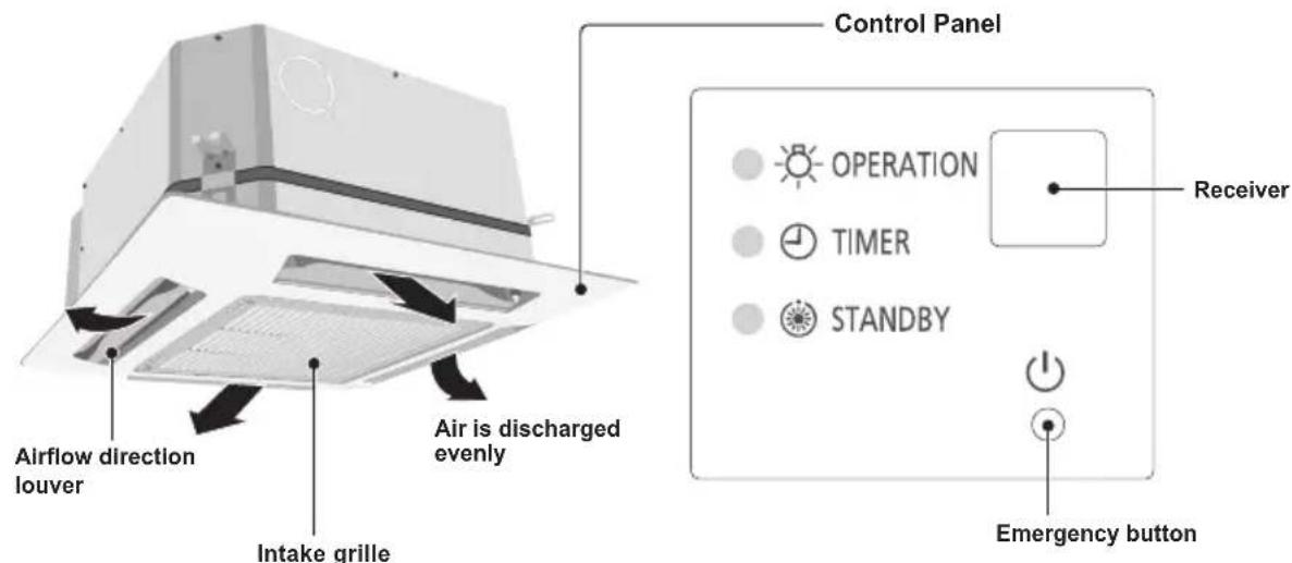
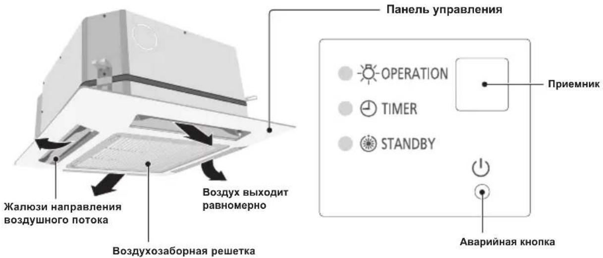
OPERATION
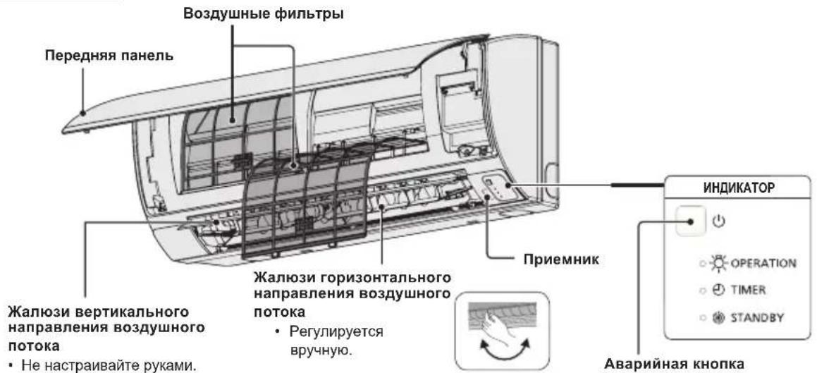
Names of Parts
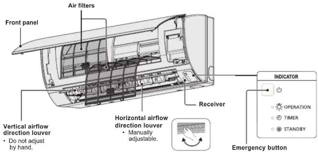
INDOOR UNIT
Y2 type (4-WAY CASSETTE 60×60)
K2 type (WALL MOUNTED)
Wireless Remote Controller (Optional parts)
NOTE
Refer to the Operating Instructions attached to the optional Wireless Remote Controller.
(Wireless type: available for all indoor units)
High-Spec Wired Remote Controller (Optional parts)
NOTE
Refer to the Operating Instructions attached to the optional High-Spec Wired Remote Controller.
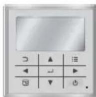
(Wired type: available for all indoor units)
Timer Remote Controller (Optional parts)
(Wired type: available for all indoor units)
NOTE
For details, refer to the Operating Instructions attached to the optional Timer Remote Controller.
ex.) Timer Remote Controller
Names and Operations
1. (Start/Stop) button
Pushing this button starts, and pushing again stops the unit.
Operation lamp :
When started light up
When stopped goes out
Operation lamp
The lamp is turned on when an air conditioner is in operation.
This lamp blinks when an error occurs or a protective device is activated.
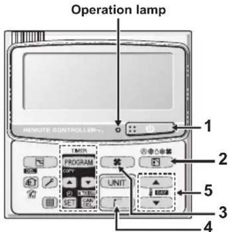
2. (Mode select) button
Pushing this button to select an operation mode.
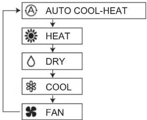
... Auto cooling-heating mode detects the difference between the preset temperature on the controller and the actual room temperature.
Then it automatically selects heating or cooling mode.
(The automatic heating and cooling control for 2WAY and mini VRF system can be performed when all indoor units in the same refrigerant circuit are controlled in a group control.)
3. (Fan speed) button
Changing the fan speed.
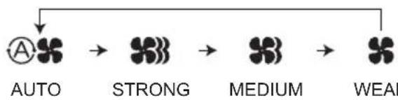
NOTE:
When Mode select button is set to FAN, AUTO mode cannot be selected.
4. (Swing/Air direction) button
Push the Swing/Airflow direction button to set the auto swing or air direction to a specific angle. (For details, see "Adjusting Airflow Direction" section.)
5. Temperature setting buttons
Changing the temperature setting.
Push the Temperature Setting buttons to change the desired temperature setting.
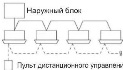
Group Control
Group control function is suitable for operating the multiple air conditioners in a large single room.
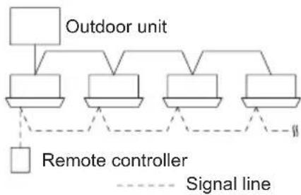
- Up to 8 units can be connected.
Operation of all indoor units in the same mode except for airflow direction. - Use the indoor unit's temperature sensor.
ADJUSTING AIRFLOW DIRECTION
The functions differ depending on the indoor unit used. The airflow direction cannot be set using the remote controller for any unit which is not listed below. Y2 type, K2 type:
- Never use your hands to move the flap (vertical airflow flap) that is controlled using the remote controller.
- When the air conditioner is turned off, the flap automatically moves toward the direction of closing.
- The flap (vertical airflow flap) moves to the upward position when performing the standby operation for heating. The swing operation is made after the standby operation for heating is released, but swing is indicated on the remote controller even during the standby operation for heating.
Setting the airflow direction
The airflow direction changes each time the FLAP button is pressed during operation.
To activate the swing operation
Press the FLAP button to set the flap (vertical airflow flap) to the downward position, and then press the FLAP button again. This displays , and the airflow automatically swings up and down.
| Heating Cooling and drying Fan operation All operations | |||
| Set the flap (vertical airflow flap) to the downward position. If the flap is set to the upward position, the warm air may not reach the floor. | The flap (vertical airflow flap) can be set to one of three positions. | Initial setting | Continuous operation |
| Initial setting |
To stop the swing operation
Press the FLAP button again during the flap swing operation to stop the flap at the desired position. Then, the airflow can be set from the top position by pressing the FLAP button again.
Indicator when swing operation is stopped
| Fan and heating Cooling and drying |
During cooling or drying operation, the flap will not stop at the downward position. Even if the flap is stopped at the downward position during the swing operation, it will not stop until it moves to the third position from the top.
ADJUSTING AIRFLOW DIRECTION (CONTINUED)
4-way cassette (Y2)
Y2 type air conditioner is equipped with auto flaps.
You can set the airflow direction to a specific angle or to the sweep mode using the remote controller.

CAUTION
Do not move the flap with your hands.
Wall mounted type (K2)
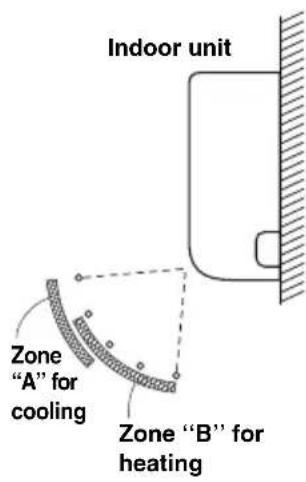
Vertical directions (automatic)
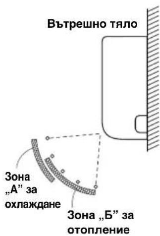
Confirm that the remote controller has been turned on. Press the FLAP button to start the flap moving up and down. If you want to stop the flap movement and to direct the air in the desired direction, press the FLAP button again. In the cool mode, do not direct the flap down and move out of the cooling zone "A", otherwise, condensation may drip on to the floor. Zone "A" is the recommended flap position for cooling.
When operating continuously in the fixed airflow direction setting for about an hour, the airflow direction is automatically controlled and the flap position is changed. The airflow direction may be different from the display on the remote controller.

CAUTION
Do not move the flap with your hands.
Horizontal directions (manual)
The horizontal airflow direction can be adjusted manually by moving the vertical vanes to the left or right.
ADJUSTING AIRFLOW DIRECTION FOR MULTIPLE INDOOR UNITS USING SINGLE REMOTE CONTROLLER (Wired)
Auto Flap () button
- If multiple indoor units are connected to a remote controller, the airflow direction can be set for each indoor unit by selecting the indoor units (see the operation below).
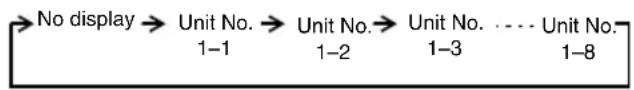
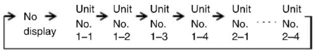
- To set the airflow for individual units, press the UNIT button. Display shows the indoor unit number under group control. Set the airflow direction for the indoor unit that is shown on the display.
Each time UNIT is pressed, the indicator changes in the order shown below. - When nothing is displayed, you can make the setting for all indoor units in one operation.
- The unit number is displayed as Outdoor Unit Number–Indoor Unit Number. It varies depending on the number of units under group control.
One outdoor unit and eight indoor units
Two outdoor units and four indoor units
SPECIAL REMARKS
"DRY"Operation
How it works
- Once the room temperature reaches the level that was set, the unit repeats the cycle of turning on and off automatically.
- In order to prevent the humidity in the room from rising again, the indoor fan also turns off when the unit stops operating.
- The fan speed is set to "LO." automatically, and cannot be adjusted.
- "DRY" operation is not possible if the outdoor temperature is 15^ or less.
Heating Operation
Heating performance
- Because this appliance heats a room by utilizing the heat of the outside air (heat pump system), the heating efficiency will fall off when the outdoor temperature is very low. If sufficient heat cannot be obtained with this heat pump, use another heating appliance in conjunction with this unit.
Defrosting
- When the outdoor temperature is low, frost or ice may form on the outdoor heat exchanger coil, reducing the heating performance. When this happens, a microcomputer-controlled defrosting system operates. At the same time, the fan on the indoor unit stops (or runs at very low speed in some cases) and the "STANDBY" indicator appears on the display until defrosting is completed. Heating operation then restarts after several minutes. (This interval will vary slightly depending upon the outdoor temperature and the way in which frost forms.)

standby) on the display
- For several minutes after the start of heating operation, the indoor fan will not start running (or it will run at very low speed in some cases) until the indoor heat exchanger coil has warmed up sufficiently. This is because a cold draft prevention system is operating. During this period, the "standby" indicator remains displayed.
- " " (standby) remains displayed during defrosting or when the compressor has been turned off (or when the unit is running at very low speed) by the thermostat when the system is in the heating mode.
- Upon completion of defrosting and when the compressor is turned on again, " " (standby) will turn off automatically as heating operation resumes.
NOTE
Should the power fail while the unit is running
If the power supply for this unit is temporarily cut off, the unit will automatically resume operation (once the power is restored) using the same settings before the power was cut off.
CARE AND CLEANING

WARNING
- For safety, be sure to turn the air conditioner off and also to disconnect the power before cleaning.
- Do not pour water on the indoor unit to clean it. This will damage the internal components and cause an electric shock hazard.

CAUTION
- Never use solvents or harsh chemicals when cleaning the indoor unit. Do not wipe plastic parts using very hot water.
- Some metal edges and the fins are sharp and may cause injury if handled improperly; be especially careful when you clean these parts.
- The internal coil and other components of the outdoor unit must be cleaned periodically. Consult your dealer or service center.
Air intake and outlet side (Indoor unit)
Clean the air intake and outlet side of the indoor unit with a vacuum cleaner brush, or wipe them with a clean, soft cloth.
If these parts are stained, use a clean cloth moistened with water. When cleaning the air outlet side, be careful not to force the vanes out of place.
CLEANING INSTRUCTIONS
- Do not use benzene, thinner or scouring powder.
- Use only soap (pH7) or neutral household detergent.
- Do not use water hotter than 40^ .
HINTS
- Clean the filter regularly for best performance and to reduce power consumption.
- Please consult your nearest dealer for seasonal inspection.
ALUMINIUM FIN
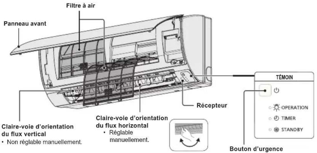
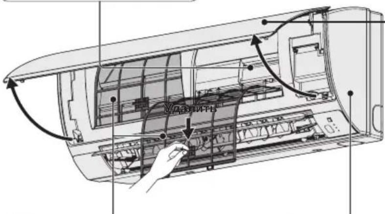
FRONT PANEL
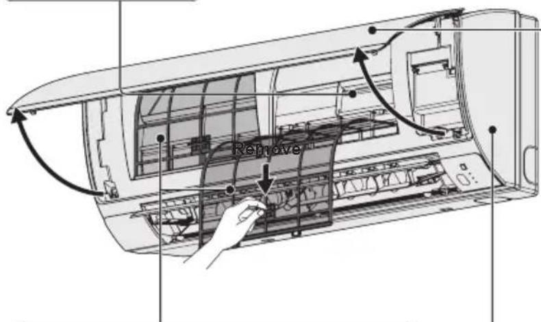
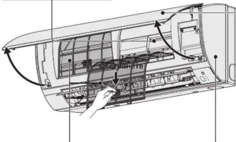
Remove Front Panel
- Raise and pull to remove the front panel.
- Wash gently and dry.
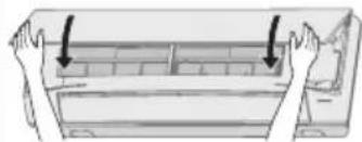
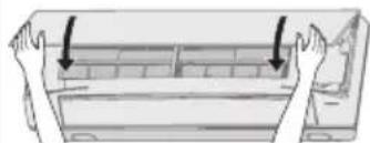
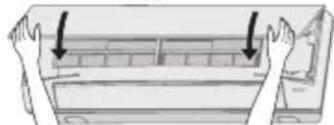
Close Front Panel
- Press down both ends of the front panel to close it securely.
AIR FILTERS
Air filters cleaning is needed every two weeks.
- Wash/rinse the filters gently with water to avoid damage to the filter surface.
- Dry the filters thoroughly under the shade, away from fire or direct sunlight.
- Replace any damage filter.
INDOOR UNIT
Wipe the unit gently with a soft, dry cloth.
ex.) Timer Remote Controller
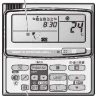
Air Filter Maintenance
It is recommended that the air filter be cleaned when the (Filter) appears on the display. Clean the filter frequently for best performance in the area of dusty or oil spots regardless of filter status.
After Cleaning
-
After the air filter is cleaned, reinstall it in its original position.
Be sure to reinstall in reverse order. -
Press the Filter reset button.
The (Filter) indicator on the display goes out.
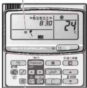
Filter indicator
Filter reset button
TROUBLESHOOTING
If your air conditioner does not work properly, first check the following points before requesting service. If it still does not work properly, contact your dealer or a service center.
INDOOR UNIT
| Symptom Cause | ||
| Noise Sound | like streaming water during operation or after operation | Sound of refrigerant liquid flowing inside unitSound of drainage water through drain pipe |
| Cracking noise during operation or when operation stops. | Cracking sound due to temperature changes of parts | |
| Odor Discharged air is smelled during operation. | Indoor odor components, cigarette odor and cosmetic odor accumulated in the air conditioner and its air is discharged.Unit inside is dusty. Consult your dealer. | |
| Dewdrop Dewdrop gets accumulated near air discharge during operation | Indoor moisture is cooled by cool wind and accumulated by dewdrop. | |
| Fog Fog occurs during operation in cooling mode.(Places where large amounts of oil mist exist at restaurants.) | Cleaning is necessary because unit inside (heat exchanger) is dirty.Consult your dealer as technical engineering is required.During defrost operation | |
| Fan is rotating for a while even though operation stops. | Fan rotating makes operation smoothly.Fan may sometimes rotates because of drying heat exchanger due to settings. | |
| Wind-direction changes while operating.Wind-direction setting cannot be made.Wind-direction cannot be changed. | When air discharge temperature is low or during defrost operation, horizontal wind flow is made automatically.Flap position is occasionally set up individually. | |
| When wind-direction is changed, flap operates several times and stops at designated position. | When wind-direction is changed, flap operates after searching for standard position. | |
| Dust Dust accumulation inside indoor unit is discharged. | ||
| At the initial high-speed operation, the fan may sometimes rotate faster (for 3 to 30 minutes) than the setting speed. | This is for operation check in order to confirm whether the fan motor rotation is within use range. | |
OUTDOOR UNIT
| Symptom Cause | ||
| No operation | When power is turned ON instantly. | Operation is not activated for the first approx. 3 minutes because compressor protection circuit is activated. |
| When operation is stopped and resumed immediately. | ||
| Noise Noise | often occurs in heating mode. During defrost operation | |
| Steam Steam | often occurs in heating mode. | |
| When stopped by remote controller, outdoor unit fan is sometimes operating for a while even though outdoor compressor is stopped. | Fan rotating makes operation smoothly. | |
CHECK BEFORE REQUIRING SERVICES
| Symptom Cause Remedy | ||
| Air conditioner does not run at all although power is turned on. | Power failure or after power failure Press | ON/OFF operation button on remote control unit again. |
| Operation button is turned off. • Switch on | power if breaker is turned off. • If breaker has been tripped, consult your dealer without turning it on. | |
| Fuse blow out. If blown out, consult your | dealer. | |
| Poor cooling or heating performance | Air intake or air discharge port of indoor and outdoor units is clogged with dust or obstacles. | Remove dust or obstruction. |
| Wind speed switch is set to “Low”. Change | to “High” or “Strong”. | |
| Improper temperature settings Refer to “TIPS FOR ENERGY SAVING”. | ||
| Room is exposed to direct sunlight in cooling mode. | ||
| Doors and /or windows are open. | ||
| Air filter is clogged. Refer to “CARE AND | CLEANING”. | |
| Too much heat sources in room in cooling mode. | Use minimum heat sources and in a short time. | |
| Too many people in room in cooling mode. | Reduce temperature settings or change to “High” or “Strong”. | |
If your air conditioner still does not work properly although you checked the points as described above, first stop the operation and turn off the power switch. Then contact your dealer and report the serial number and symptom. Never repair your air conditioner by yourself since it is very dangerous for you to do so. You also report if the inspection mark and the letters E, F, H, L, P in combination with the numbers appear on the LCD of the remote control unit.
TIPS FOR ENERGY SAVING
Avoid
- Do not block the air intake and outlet of the unit. If either is obstructed, the unit will not work well, and may be damaged.
- Do not let direct sunlight into the room. Use sunshades, blinds or curtains. If the walls and ceiling of the room are warmed by the sun, it will take longer to cool the room.
Do
Always try to keep the air filter clean. (Refer to "CARE AND CLEANING".) A clogged filter will impair the performance of the unit.
- To prevent conditioned air from escaping, keep windows, doors and any other openings closed.
NOTE
Should the power fail while the unit is running
If the power supply for this unit is temporarily cut off, the unit will automatically resume operation once power is restored using the same settings before the power was interrupted.
TABLE DES MATIÈRES
Page
INFORMATIONS SUR LE PRODUIT 16
PRECAUTIONS DE SECURITE 16
EMPLACEMENT D'INSTALLATION 17
INSTRUCTIONS RELATIVES A LALIMENTATION. 17
CONSEILS DE SECURITE 18
INFORMATIONS 20
OPERATIONS 21
RéGLAGE DU FLUX D'AIR 23
AJUSTEMENT DE LA DIRECTION DU FLUX D'AIR POUR PLUSIEURS UNITS
INTÉRIÉURES À L'AIDE D'UNE SEULE TÉLECOMMANDE (FILAIRE) 25
REMARQUES SPECIALES 26
ENTRETIEN ET NETTOYAGE 26
DEPANNAGE 28
POINTS A VÉRIFIER AVANT DE SOLLICITER UNE RÉPARATION 29
CONSEILS POUR ECONOMISER DE L'ENERGIE 29
CHARACTERISTIQUES 172
INFORMATIONS SUR LE PRODUIT
Type K2 (MONTÉ AU MUR)
Bouton Auto Flap (UNIT)
Cassetta a 4 vie (Y2)
(1) GWP = global warming potential (broeikaseffect)
Botão Auto Flap (UNIT)
Remover o paine frontal
IIAHPOΦOPIE Σ I A TO I P O I O N
Av exETe TPOBAneta n atopiec oxetikα μe To kλiataotiko oας, θα xpeiaoteTic TAPAKATW Tlnpoopopiec. O apθμoc movTeAou kai o auεw apθμoc βpiokovtai OTNV tivakiδa Tns ouakeunç.
Kata mTv evapn aaveBc KaTm diaKOTn 0BVEI
Auxvia etroupyiac
Ctp. INHOPMALI 3A IPOJYKTA 114
MEPKI 3A BE3OJACHOCT 114
MRCTO HA MOHTAX 115
N3NCKBAHnKbM EJIKTP03AXPAHBAHETO. 115
NHCTPYKUIM 3A BE3OJACHOCT. 116
UHΦOPMALI 118
EKCJIIOATALI 119
PERYJINPAHE HA IOCOKATA HA Bb3dUHHN IOTOK. 121
PERYJINPAHE HA IOCOKATA HA Bb3dUHHNIO TOTOK 3A HRAKOJIKO BbTPEUHN TEJA,
KONTO N3NOJ3BAT EINO (XNUHO) INCTAHIOHNOHYNPABJIEHNE. 123
CNEUJIHIN BENEKNI 124
IIOHCTBAHE I IPIXNI 124
OTCTPAHRAHE HA IPOBJIEMN 126
PPOBEPETE CJIENHOTO INPEIN DA NONCKATE CEPBN3HO OBCNJXBAHE.127
IIOJIe3HA INHOPMALINr 3A INKOHOMn HA EHEPTnR 127
CNEUINKALIN 172
INHOPMAU3A PPOyKTA
Ako mATE npo6nEMn INBnPoCn, Cbbp3aHn C KInMaTnKa, CneHaTa NHΦopMaunrue Bn 6bDe nOe3Ha. HomepbT Ha moDena N cepuHnRT Homep ca Ha TaBeJATA B DoHata Yact Ha shkaFa.
MoDcN No. CepnEn No.
ДаТаHaЗakупвае
AdepesHa npodabauna
TeJefoHEn Homep
MEPKN 3A BE3OINACHOCT
CneHNHTe CnMBOJN B HAcTOnHsTa MHCTpyKzra 3a eKcNlOaTaunCe n3NON3BaT, 3a Da BN npedynpeaT 3a NOTeHuaHNo OAnCHy cNOBna 3a NOTpe6nteNTe, cepBn3HnepcoHaI nn ypeda.

ONACHOCT

BHIMAHNE
To3n CUMBOJ 6o3Haayaba OnaCHO TIN ONaCHO DeiCTBNE, KOnTO MORAT Da IOBeaT DO TEKKN TeJIeCHN NOBpeDN IIN CMbPT.
To3n CmBOJ 6o3Haaba OnaCHO HIN ONaCHO DeICTBNE, KOINTOMARAT Da DOBeaT Do TEJIeCHN NOBpeDN, BpeDN Bbpx npOdyKTA INI DpyrO NMyueCTBO.
MRACTO HA MOHTAX
- PpenopbYBaMe TO3N KJIImatNK Da Ce HCTaInpA OT KBaINHcUpaHN MOHTaxHH TeXHnB C bOTBetCTBne C nHCTpyKUnnte 3a MoHTax, NpeOCTaBeHN C ypeDa.
- PpeiMoTAtk IpoBepTe DaI HAnpeXeHHeTo Ha eJeKtpuYeCKTo 3axpaHaBaHe B DoMa IIN OΦnca BN CbOTBeTCTBa Ha yKa3aHn BONTxH Na pa6pnHata TaBeJIka.

ONACHOCT
He MoHTnpaIte To3n KJIIMaTnK Ha MeCTa, KbTeO NMa H3napeHnN nn NeCHOB3PnAmeHmRra3OBe, INN B MHORO BLaJXHa CpeDa, HanpImep B opAHxepnn.
He MoHTnpaTe KInMaTnKa Do IpeMeTu Nn OBeKTu, KOITo ReHepuPc TnHa TOJIiHa.
N36aBaeTcneHTo:
3a da npednataTe KInMaTnKa OT CnHa Kopo3n, He MOHTnpaTe BbHNoTO TAno Ha MeCTa, KbTeTo MoKe Da 6Be Ne3PbckaHo OT CoNeHa MOpcka BoJa Nn E n3IOXKeHO Ha HacnteH CbC Cpa Bb3DyX B 6N3OcT Do MNHepaJIHa BOJa.
N3NCKBAHNA KbM EJEKTP03AXPAHBAHETO
1.Oka6eHbAHeTO Tp6Ba Da e B CbOTBeTCTBne C MeCTHnTe CTaHApTN 3a eEnKtpnueckn HCTaIauu.3a noPbO6Ha HΦopMaunCe KOHCyItnpaIte Ce c npOdaBaay nIc KBaIINpUpaH eNEKTPoTeXnK.
2. BCEKMOyI Tp6Ba Ia 6bIe HADNeXHO 3a3EmH NocpeDCTBOM 3a3EMNTeH NPOBOHN Knn Ype3 3a3EmBAHeTo Ha 3axpaHbAunKa6en.
3. Cbbp3BaHTo KbM eNektpnueckata nHctanaun Tp6Ba Da ce n3Bbpwn OT KBaHnФu npaH eNektpOTexHnK.

BHIMAHNE
3a da ce 3arpee cnctemata, cHTpaHnHO eI. 3axpaHbaHe Tp6Ba da ce BkIOUH HAI-MANKO 5 (net) yaca npEdu da 3anoHete da n3NON3Bate. Octabete cHTpaHnOeI. 3axpaHbaHe BkIOUeHO, OCBEN aKO Hama da n3NON3Bate ypeDa 3 npoDbJNXTeHEN nepNOd OT BpeMe.
LcHTpaHno eNeKtpnuecko 3axpaHbaHe

BKJ.
BENEXKA
I3KJIIOHcTe 3axpaHbuaa Ka6eI OT KOHTaKa I npeKbCbCaHa Ha cEHtpaHTo 3axpaHbAe, aKO HMa Da N3NOJ3BaTe KJIIMATka 3a Dblr nepnoD OT Bpeme. Korato Ce N3KIOuAt HAKOIT BbHUnTE INN BbTpEunHInTe TEla, cJaTa CnCTema He MoKe da CE N3NON3Ba.
INHCTPYKUN 3A BE3OJACHOCT
- PpOHTeTe BnHMaTeJIHO Te3N INcTpyKuIN 3a ekCnIIOaTuIN ppeIN 3a nI3NON3BaTe KInMaTnKa. Ako BCE OUIE I3NIITBaTe 3aTpYdHeHIN INI np6bNm, OobPheTe ce 3a NOMOU KbM npOdaBau.
To3n KInMaTnK e npEHa3NaeH da OcnHypRa npiAHTha aTMoccepeBa NomeeHn. N3noI3BaITe ro eHNCTBeHO nO npEHa3NaeHne, KaKTo e ONICAHO B HAcTOUITE INHCTpyKm 3a EKcNlOaTaun.

ONACHOCT
NcKaIte noTbPjKeHne OOTOpn3npaH nnIbp nIN cNeuaJIncT daII MoKe Da ce N3IOJ3Ba pa3NIuHe TnXlaIIne HareHT. N3IOJ3BaHeTo Ha XlaIIne HareHT, KOTo e pa3NIuHe OT OnpeJeHeHn TnI, MOKe Do npEiN3BnKA IOBpeHa Ha IpoDyKTA, EKcPiIO3n, HapaHBAHe Hp. HeKeJaHn IocJIeCTBnI.
Hnkora He DoKocBaIe YpeDa C Mokpn pIue.
Hnkora He n3noJ3BaIte nnCKnJaIpaIte 6eH3n Hnn DpyrBBeueCTBa C neCHO 3anaJIIMn napu B 6n3OcTdo KImMaTnKa -TOBa e N3KIIQUHTeJIHO ONaCHO.
He n3non3BaIte To3n UpeB BBB B3pNBOONacHa CpeJa.
To3n KInMaTnK HmAbeHTnlaTop, KOITo Da BkapBa YnCT Bb3dyx OTbH. Tpa6Ba YecTO Da OTbaprTe BpATne INn npO3OpUte, KOraTO B CbIoTO NOMEseHne IN3NON3BaTe OTOnIINTeHNy UpeNc rA3, NaTAtu INn dp. NIO6Hn, KOITo npn pa60Ta IN3raprT 3NaHTeJIHO KOnIyEcTBOOT KInCNoPoJa BB Bb3Dyxa B cTaNtA. B npOTnbEN CnyaJ CBueCTByBa DOpN OnaCHOCT O3aNywaBaHe.
OcnrypeTe OTdeneH en. KOHTaKT 3a BCEKn ypeI, KaKTo n ceHTpAneH ppeKbCBAu 3a 3axpaHbAHeTO, ppeNa3nteN Ha Bepurata n peDna3nteN 3a 3a3emNTeJHaTa Bepurra 3a 3aunTa CpeU cyBpbXtOK 3a To3n OTdeneH TKOB KpbI.
OcnrypeTe oTdeHen en. KOHTaKT 3a BceKn ypeI, KaKTo n
nblHa DBycTpahHn 3aunTa, KOrTO pKeKbCBA
3axpaHbAHeTO BvB BCNUKN PONHcN I e INTErpnpaHa B
OKa6eJIbAHeTO CbOTBeTCTBne Cbc CTaNdapTNTe 3a
OKa6eJIbBaHe.
3a Da ce npedotbpaTOnaCHOCTN, KOTo MoarTaDa Bb3HKnHaBpe3yntaT Ha HapyuShaH3OlaUra,ypebT TpA6Ba Da 6bDe 3a3EmeH.
IOnHCTBaHETO Ha BbTpEshOCTTa Ha BbTpEshHOTOnBbHNHTO TAno He TpRbBA Da ce N3BbPwBA OTnOTpe6nteNTe.AhraXnpaTe OTOpN3UnpaH dInbp nnCneuaJIncT 3a NoHCTBaHETO.
He ce onntbaIte camn da nonpaBInTe ypeDa B cnUyai Ha nobpeDa.3a peMOHT Ha ypeDa ce CbbpKTe c OToPn3npaH TbproBeu nn cepBn3.
I3TnueHe Ha oxnaJdaunra3 MoKe Cb3JaDe onaCHOCT OT noXap.
No cbo6paXeHn 3a 6e3oNaChOCT BuHaRn n3KnIOuBaIte KImMaTnKa u 3axpaHbAHeTo My npEi NoocTBaHe u o6cnyXBaHe.
Ipiuabapn H3KIOUOte KJIMaTnKa OT eNEKtpueeCKOT0 3axpaHbAHe, KaTO N3DbPNaTe UeIcEla O T KOHTaKaTa, I3KIOUChTE PpeKbCBAca UNI N3KIOUChTe 3axpaHbAHeTo.
He IbxaIte npbCTnTe cn INI pyrN ppeMeTn BbB BbTpseHHaTa INI BbHHaTa Yact Ha KINMaTnKa, TbKATO BbptTAnTe ce YaCTN MoKe da npuHrt HapaHBAhe.
He n3non3BaIte MoDnOuPan Ka6eN, o6u Ka6eN, yDbLnKInTe NIN HeOTROBapu Ha n3nCKBaHnra Ta Ka6eN, 3a Da ppeDoTbPaTne nperepBahe n noxap.


ONACHOCT
Cnpete da n3noJ3BaTe npOdyKta, KORato Bb3HnKHe
aHOMaJIra/NOBpeJa n3BaJeTe UeNcEla O T KOHTaKa IIM
n3KJIIOUeTe OT KONyTe N aBTOMaTHHnI PpeBKJIIOUbaTeI.
(Ima pIckOT nyueK/Noxkap/TOKOB yIap)
PiPmepu 3a aHOMaJIra/NOBpeJa
3a3eMHTeJIHnT aBTOMaTHueH npeKbcBaY (ELCB) YecTo Ce aKTINbpa.
- Yceua ce Mmnpc Ha n3ropaNo.
- CyBaCe Heo6nuaeH yum nn npyepbT Bn6pnpa.
- N3Tnua BOa O T BbTpewHnrypeI.
- Ka6eIbT nII nIeNceIbT ca Heo6nuaHno ropeu.
- CkopoCTTnaBaBHTnlaTopaHeMoXeJaCe KOHTpOInpa.
- YpeIbT cnpa pa60Ta BeHara, OOpn n Da e BkNoueH da pa60Tu.
BENTnlaTopbT He cnnpa,do np,ako ypeDbTe cnpna da pa60tn.
BeHara ce CbpxKeTe c MeCTHnT bProBeu 3a noDpBkKa/peMOHT.

BHIMAHNE
To3n ypeI e npedHa3HaueH 3a n3non3BaHe O T ekCneptn IInn o6yehn noTp6bnteN B TbprOBcKn 06eKtN, B Jekata npomuJleHOCT, BB fepMn IIN 3a TbprOBcKn cEJIOn OT HeCneuaJIncTn.
He BKJIOUbaIte N3KJIIOUbaIte KJIMaTnka OT KJIIOHa 3a ceHTpaHOTo 3axpaHbAhe. N3NoI3BaIte 6yToHa 3a nyckaHe n cnipaHe BKJI./N3KJI. (ON/OFF).
He Mykate Hnio B n3xoHnO TBOp 3a Bb3dyX Ha BbHnHOTo TAnO. TOBa e OnaCHO, Tb KaTO BEHTnlaTopbT Ce BbPTN C BnCOKA CKOPoCT.

He DOKOCBaIte BXOHN OTBOP 3a Bb3dyx INN OCTpIte anyMNHeBn pe6pa Ha BbHNoTO TANO. MoKe da ce HapaHnte.

ДрьхтпpoTNBOIOnoxapHaTа anapMa nИЗХОДнHT OTBOP 3a Bb3dUx Ha Hau-MaIIKO 1,5 M OТ уpeda.
To3n ypeJ moKeJa Ce n3noJ3Ba OTea Ha Bb3pact Ha 8 roDHH n OT IuCa C HamaJeHn Fm3nueckn, CEH3OpHN UIN yMCTBHeH cNoC6HOCTn, INn HA KOnTO JInCBa TOnIT nIO3HaHn, aKo Ca nOd npAkr HAd3Op Ha JInCe, KOeTO OTROBApra 3a TAn, INn Ca nMa DaDeHn IHCTpyKcNn OTHOCHO be30NaChata pa60Ta Cypea n Te pa36bnapat ONaCHOCTITE, CBbp3aHn C TOBA.
He oxlaaJaTe n He 3aToIaJIe TpeKaIeHO MHO romeueHHeT0, aKo B Hero ce HAMnPat 6eBeta ININ INBaIIn
He MykaTe npedMeTn B Kopnyca Ha BeHTnIaTopa.


Taka mokeTe da ce HapaHnte nn da NOpeDnte ypeDa.
He cdaTe n He cTbNaTe Bbpxy ypea. Ima onaCHOCT da naHete.

3ABEJIEXKKA
KOMnpecopbT noHrkora cnnpa nO BpeMe Ha rpbMOteBnHn 6ypn. Toba He e MexAHnuHa nobpea. YpeBbT aBTOMaTHHO Bb3TaHOBRA pa6oTaTa CNcIeH NAKOLKO MNHyTu.
OpunnHaHHTeKCTHaTe3n HhctpykCmEhaahrnnckn e3nk.Tekctobete Ha octaHaHNTe e3nCa npeBODHa opunnHaHHTe HhctpykCmN.

Cnpete n3noJ3BaHeTo Ha KInMaTnKa, aKO ToI pa6OTn HeoBnauHNo IIN Bb3NkHe NOBpeDa, n 3BaTe Te cenceTa ot KOHTaKta.
(Onachoct OT 3aHIMBaHe/NOxap/TOKOB ynap)
Ppimepn 3a Heo6uhaHa pa60Ta nJIn nobpeda
-KnImatnkbt He cTaptnapa Korato e BKJIOueH.
- 3axpaHbHeTo npeKbcBa, KOrato Ka6enbT ce MeCTn.
-Mnpnue Ha n3ropno nn n3daBa Heo6uaeH ym npn pa6ota.
-KopnycBTe deΦopMnpan Hn Hno6uauHOroepu.
3a noDpBkKa nnpeMOHT ce CBpXeTe ce He3a6abHO C MeCTHnTbproBeU.
BAKHA INHΦOPMALU, KACAEUa N3NOL3BAHNA XJADNJIEH AFEHT
To3 npOdyKT cbIbPka fnyopupaHn napHKnOBn ra3OBe, KOHT ca BkJIoueHN B IpotoKoNa ot Knoto. He 3XbPnHte ra3OBe B aTMocepapa.
BnHa xnaunnna areHr: R410A
TIN3(1) CTOnHOCT: 1975
(1) 3 = 06a宝 He noteHuaHa 3aToTnHe
Bb3MOxHc e da ce n3NcKBa nepnoDnUHa npOBepKa 3a n3TnueHa XnaIneH areHT cbrNacho ebPoneckoto N MeCTHO 3aKOHOdaTeNCBO. 3a NOBEe NHΦopMaunCe obpHeTe KbM Baun DaNbP.
HHΦOPMALIa
YcNoBnHa eKcnIoTaun
I3no3BaIteTo3nKImatNkBcIeHInTeTEmpeaTyprnIpaHnI.
| Външи тela Вътравна Bъшna | ||
| mini (Tin LE1) | РекIM oxлajданe 14°C ~ 25°C (*WBT) -10°C ~ 46°C (*DBT) | |
| РекIM отолени 16°C ~ 30°C (*DBT) | -20°C ~ 18°C (*WBT) -20°C ~ 24°C (*DBT) | |
| 2WAY (Tin ME1) | РекIM oxлajданe 14°C ~ 25°C (*WBT) -10°C ~ 43°C (*DBT) | |
| РекIM oтолени 16°C ~ 30°C (*DBT) -25°C ~ 15°C (*DBT) | ||
| 3WAY (Tin MF2) | РекIM oxлajданe 14°C ~ 25°C (*WBT) -10°C ~ 46°C (*DBT) | |
| РекIM oтолени 15°C ~ 30°C (*DBT) -20°C ~ 18°C (*WBT) | ||
| РекIM oxлajданe и отолени | --10°C ~ 24°C (*DBT) | |
DBT: Temnepatypa Ha cyx TepMometbp
WBT: TemnepaTpa Ha MOKbp TepMOMeTbp
IhOpMaun 3a c6bupane n n3xBbplnHe Ha cTapn eJeKtpoypeu n 6aTepn
Te3n CmB0H, NOCTaBeHN Ha npOdyKTnte, ONAKOBKNTe N/NN CbTCTBaUNTe rN DOKymeHTN 6o3Haabat eJekTpOHn ypei, KOnTO He Tp8Ba da 6bDat N3XBpbJHn 3aeJHO C NOTOKa 6ntOBn OTnaDbu.
3a da 6bdaT npabunHO TpeTpapnH n peuKnpaH, MOna da npedeTe Te3n npodykTu Ha CneuaHNO npedHa3HaueHHe 3a Ta3n ueMecTa, cna3BaNKn pa3npoe6nte Ha HauMOHaJHOTo 3aKOHOaTeIcTBO u EBpOeNckNTe DnpeKtNBn 2002/96/EC n 2006/66/EC.
Cn3BaBnK nHCTpyKuNTe 3a npabNlHOTo 3XbPnIe Ha TaKNa ypei n 6aTepn, Bne Ie NOMOrHeT da 3aNa3IM cEHNN pecypcN n Da npedOTbpaTm Bb3MOxHn HeratNBn epeKTn Bbpxy OBeUkOTo 3dpabe n OKoHaTa Cpea.
MOnr, 06bprHeTe Ce KbM MeCTHnTe O6uHcKn Bnactn Nll TbpROBCKn O6eKT, OTkbTeO CTe 3aKynnn npOykTa, 3a da nOlyuHTe DoTbHnTEHa HhOpMaun 3a Ha-6n3Kn Cb6pAteIeH NyHK Tnn MRCTO 3a N3xBpRnHe Ha cTApn EneKtpoypeuN 6aTePm. PInn HapabINHO 3XbPnIe Ha ypea, MoKe da nOheCe Haka3aTeHa OTROBOPHocT, B cbOTBeTCTBne pa3npoe6nTe Ha HauNoHa JnHoto 3aKohOdaTeNCTBO.
3a 6n3Hec nOtpe6nteJN B Ebponeckna CbIO3
Ako XeIaeTe Da n3XbBpNITE HeHyXHn eIeKTpOpyPei, MOJI CbBpXeTe Ce C BaIIN dIITbp IIN DOCTaBcIK 3a NOBEue INHcpOpMaun.
[HHΦopMaun 3a CtpaHn n3BbH EbponecknCbIO3]
Te3n CmB0n Ca BaIaHn CaMo B paMKte Ha Ebponeckn CbIO3. Ako JeaTe Da ce ocBO6OJTne OT Te3n OTNaDbUHN npOyKTn, MoJc CBpKeTe Ce C MeCTHne OprAH NaBlaCTT a NIN BaUN JOCTaBvNK, 3a Da nOlyuHTe INHOpMaun 3a TAXHOTo KopeKTHO uXbPJIHe.
![PANASONIC S45MY2E5A - [HHΦopMaun 3a CtpaHn n3BbH EbponecknCbIO3] - 1](/content/2026/03/496428/images/5d29df1af591efe4d482983653c53c4b95a2c1380fe06067357a50f4a0e39480.jpg)
3a6eJekka 3a cHbONITE Bbpxy 6aTePN (nocleHnTe DBa CmBOJa B JARBO):
Te3n CmBONM MOra Tda 6bDat N3No3BaHn 3aeDnO C XmMueckn CmBOn. B TaKbB cIyauN Te Cna3BaT n3NCKBaHnTa ONpeDeJIeH N OT DInpeKTNa 3a CbOTBETHN XmMkaJ.
Pb
EKCПLOATAЦИ
HaMeHOBaHnHa KOMNoHEHTNTE BbTPEuHo TAO

Tun Y2 (4-ΠbTEH KACETEH 60x60)
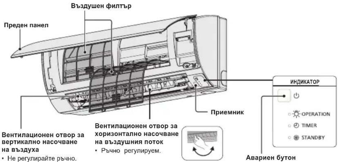
Tun K2 (CTEHEH)
CBeToHnIkaTOp 3a pa6oTa
CBeONHdkaTopbT CBETN, KORATOKNIMATKbT pa6OTn.
To3n CBeONHdkaTop 3anOyBa da Mna, aKO Bb3HkHe rpeuKa nIe ce AKTNBnpa3aHTHO yCTPOINCTBO.
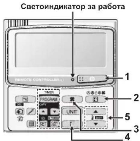
2. ByToH, M36Op Ha peKIM"
C HATNCKaHe Ha To3n 6yToH ce n3bUpa pexkmbT ha pa60Ta
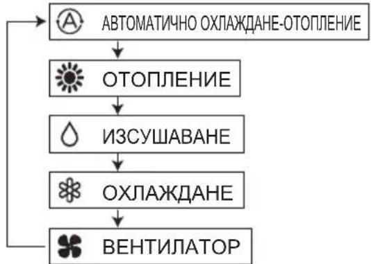
...BpeKIMHa aBTOMaTHHO
oxnaJaHe-OTOnnHHe KInMaTKnB TOnpeDena pa3Nkata MExdy 3aJaDeHata Tempepatya OT DCtAnuOHnO n peanHata Tempepatya B CtaTa.
CneT OBA aBtOMaTuHNO u36uPa peKIM Ha oxnJaHa He HN OTOnnHeHne.
(ABTOMaTmHOTO ynpabJIeHne Ha OTONJIeHHeTo I oxnaxKaJHaTeO C 2WAY nI mini VFR CnCTeMn E Bb3MOxHO, Ako BCNUBnBbTpEHN TeJA B eINH N cbU KpbI Ha OXnJaAuaAreHTN Ce ynpabJIaBAT KaTO rpyna OT DnCTaHcUHHO.)
3. ByToH ,CKopoCT Ha BeHTnataTopa"
PerynupaHe Ha ckopocTtHa BeHTnataTopa.
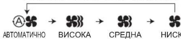
BENEXKA
Korato 6byoht3a pekIM eB no3nua BEHTIATOP, He moKe da ce n36epe ABTOMATUHEH peKIM
4. ByToH,JIIOeEHe/IOcOka Ha Bb3dYxa"
HaTnchete 6yToHa,IIIOJIeHe/IOcoKa Ha Bb3dyxa", 3a Da n36epTe aBtOMaTHHO IIIOJIeHe Ha Jxany3nte IIN OnpeJeH bIbN Ha NOJABaHc Ha Bb3dyxa. (3a NOBeue INHOpMaunr BIXKTe pa3dien, PeryIIPAhe Ha NOCOKaTa Ha Bb3dyuHnA NOTOK").
YnpaBneHHe Ha rpyna KnMaTnCn
Функцята 3a ynpablenHe Ha rpyna nO3B0nIyBaynpablenHe Na HЯKOLKO KINMaTnKa B eDHO NcBIO rONrMO NOMEseHne.
Morat da ce cbbpxaT do 8 TeJa.
- UnpabJIeHHe Ha BCNUKn TeJa B EINH N cbIePekIM cN3KnIOUeHHe Ha NOCOKaTa HA Bb3dYuHnA NOTOK.
- N3noJ3BaIe ceH3opa 3a TemnepaTypa Ha BbTpeUHOTraNo.

IuctaHIOHO ynpabneHnE
CnHnna
PERYUNPAHE HA NOCOKATA HA Bb3dUshnI NOTOK
Функшпгсе pa3ичавВТЗИСМОСТ OT ИЗПОЛЗВАHOTOBbTpeSHO TЯNo.ПOCOKATAHa Bb3dUshnI NOtOK 3a ypeN, KOnTO He ca BKIIIOUeH N CBNCbKa NO-ДONY, He MOKe Ja ce peRylnpa nocpeDCTBOM INCTAHUNOHHOTY npabJIeHne.
Tyn Y2, Tyn K2:
- Hikora He n3non3BaIte pIe, 3a da npemecTne Jxany3nte (BepTKaJIHnTe Jxany3n) 3apeyInpaHe Ha Bb3dyuHnA NOtOK, KOITc ce ynpablaBAt Ype3 dNCTaHIOHHOTo ynpabIeHne.
Korato KINMaTnBcT Ce n3KnHou, XaJy3nTe ce 3aBbPtaT aBTOMaTHHO Do 3aTBOpEH NOJOKHeH.
KaIy3nTe (BepTnKaJIHnTe JkAyn3n) npemHaBaT nOCTaBaT B ropHo nOJNOxKeHne, KOraTO ce n3IbJIHraBa cyHKzua 3a OToJIeHne B pexHM Ha n3UaKBAHe. CyHKzuaTa 3a JIOJeEhe Ce aKTINbnpa CNeI KaTO cyHKzuaTA 3a OToJIeHne B pexHM Ha n3UaKBAHe npNKIOuH. INdkaTopbT 3a JIOJeHne oBaue ce NOKa3Ba Ha dncnJe Ha dncTaHIOHHOTO ynpabJIeHne n DOKaTO ce n3IbJIHraBa cyHKzuaTa 3a OToJIeHne B pexHM Ha n3UaKBAHe.
Perynpahe Ha nocokata Ha Bb3dyHnna NOTOK
3a da aKTbBnpate ФункцИТа 3a "JIOJIeHe":
IocokataHa Bb3dyuHnT NtOK Ce npomeHa C BcKaHO HATnCKaHe Ha 6yToHa FLAP no BpeMe Ha pa6Ota.
HaTnCHeTe 6yToHa FLAP, 3a da npemecnte XaJy3nte (BepTnKaHInTe XaJy3n) B haJ-donHO noJooKeHne, n cIe TOba HaTnCHeTe OTHOBO 6yToHa FLAP. Ha ekpaHa ce nokaBa N Bb3duHnata CTpyr 3anoUba ABTomAtuHo Da ce DnKn Harope-HaDony.
| Отолени Охлajдане и обсорбигане | На влага | Равotingу на Велиниатoga | Всякни рунокции |
| Настойеше жалузITE (ВертукалнITE жалузи) тaka,谁能 сочат надoly. Ако жалузITE сочат наогоpe, Тонлайт Bьздух може за He достагнедо пда. Начални настroyки | ЖалузITE (ВертукалнITE жалузи) могат за се настrogate на edna оТ Трп Bьзможи поздции. Начални настroyки | Посторнaya пожима на bгва Бerga История пожима на bгва |
3a da cnpeTe NOCTOHHHaTnPOMHa Ha bIbIa (IOJIeEHeTo) Ha KaIy3NtE
HaTnCHeTe OTHOBo 6yToHa FLAP (3a ynpabHeHne Ha Xany3nte),doKaTo FyHKuHTa 3a JIOJIeHe Ha XaIy3nTe e BkIIOHe,3a Da rN cIpTe B XeJHaTa N03uHr. CJIeD TOBa Bb3dUHHrT NOTOK MOKe da ce perynipa OTHOBo Do Hau-TopHO NOnOxHeHne, KaTO HaTnCHeTe OTHOBo 6yToHa FLAP.
Hndkatop,he yHKunra 3a IIOoeHe e BkIIOyeHa
4-ntbTeH KaceTeH (Y2)
KJIMMaTnUte OTe TnOBe Y2 ca o6OpyDbaHn c aBTOMaTnHn KaIy3n.
Moxete da 3aadaeote onpeedehe na nocoka ha Bb3dyuHnnotOK uIN da BKIOHTe cyHKUraTa 3a IIOJIeHe Upe3 duCTaHcNOHHOTO ynpabJeHne.

Hnkora He Mectete KaIy3nte c pbue.
BHIMAHNE
CTeHeH TnI (K2)
BepTKaJIHo HacoUBaHe (abTomatuHO)
PpOBepTe daIIN dNCTaHUNHOy npabHe nE BkJIOyeHo. HAtncHe 6yToHa FLAP 3a da cTApTnpate fynKunrTa 3a IIOeene Ha Jxay3nTe. Ako JxelaTe Da cnpeTe Jxany3nTe n da HacOHTe Bb3dyuHaTc Tpyn B ONpeJeHa NocOka, HATncHe OTHOBO 6yToHa FLAP. B pExHM Ha OXIAKdane He HACoBaIte XAY3nTe HaONy n He rN HAcOVAIte N3BbN 30HaTa 3a OxJaKaDhe "A". B npOTIBen CnyaH KOnDeH3nPaHaTb Blara MoKe Ja 3anOHe da KaNe Ha noJa. 30Ha ,A" e npenOpBHTeJIHaTaN03nHn Ha XAY3nTe B pexHM Ha OxJaKaDahe. AKO KInMaTbT paobTu B eHa qIKCnpaHa N03nHn Ha XAY3nTe 3a OKoJo Yac, nocOKaTa Bb3dyuHaTc Tpyn Ce perynpa ABtOMaTHUHO n N03nHrTa Ha XAY3nTe ce IpomEH. Pocokata Ha Bb3dyuHaTc Tpyr MoKe Da e pa3nnuHa OT NOKa3aHOTo Ha DIncPiEr Ha dNCTaHUNOHTO ynpabHeHne.

BHIMAHHE
Hnkora He Mectete KaJy3nte c pbue.
Xopn3oHTaJIHo HAcOuBaHe (pbUHO)
Xopn3oHTaHTo perynnpaHe Ha nocokata Ha Bb3dyuHnnoTOK cTaBa, KaTO pbHcE Hacoyat BePTNKaJIHnTe PnaCTnHn HaJIABO INI HAJACHO.
PERUINPAHE HA NOCOKATA HA Bb3dUHHN IOTOK 3A HAKOJIKO BbTPEHNI TEJA, KONTO N3NOJ3BAT EDHO (XNUH) INCTAHUNHO YNPABJIEHNE
Bytoh Auto Flap (UNI3a ABTOMATUPOperynipane Ha no3nuraHa Kaany3ne
- AKOBmIINCTaHIOHHOTyynpaBnEHeMa CaCBbp3AHN HAKOKNBOBtpeuHnTeNa,NOcOKaTaHa Bb3DyHnI NOK 3a BCaKO OT TAX MOKe Da ce perynnpa, KaTo ce n36epeCbOTBTHTHO BtpeuHnTINO (BNXTE ONICAHNeto Ha Ta3n ONEpaunno-Dony).
- 3a da perynipate Bb3dyuHnna Notok 3a otDeJeHo TAno, Hatachte 6yToHa UNIT. Ha dncnne no ynpablaBaHa rpyna ce noka3Ba Homepa Ha BbtpeHhOto TAno. 3a daite NocOKaTa Ha Bb3dyuHnata Ctpya 3a BbTpewHOTo TAno, KOEt e Noka3aHO Ha dncnne.
C BCaKO HaTnCKaHe Ha 6yToHa UNIT, HnDnKaTOpbT ce npomeH no noka3aHnno-dony HAHN. - AKo He Ce NOKa3Ba HnIO, CaMO C eNHO DeIcTBne MOKeTe Da 3aJaIeTe HAcTpoIKu 3a BCNUBbTpEuln TeJa eHOBpeMeHHO.
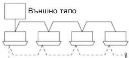
- HomebT Ha cBoTBHTo TAno ce noka3Ba noD Outdoor Unit Number-Indoor Unit Number (Homep Ha BbHnO TAno - Homep Ha BbTpEwHO TAno). ToI He e nocToHaHeN 3aBnCn OT 6po HA TeJATA B ynpabJIbaHaTa rpyna.
EHNOBbHNO TANOIOOCEMBbTpewHnTeNa
| →Hama | →Tano No. | →Tano No. | →Tano No.··· | →Tano No. |
| Индikаця над дислед | 1-1 | 1-2 | 1-3 | 1-8 |
DBe BbHnH TeHa NcTnpu BbTpewHnTea

CNEUJHNI BJIEXKNU
Pa6oTa BpeKIM ABCOPBnPAHE
KakФункционира
CneI KaTo TemnepaTpya B nOmeueHneTO DOCTURHe 3aJaDeHaTa CTOHOC, TJIOTO 3aNoUba Da NOBTapra UKbJ Ha aBTOMaTHUHO BKJIIOUBaHe N3KJIIOUBaHe.
3a da ce npedotbpatn HOBO yBEnuHaaBaHe Ha BnaXHOCTTa B nOmeueHneTo, BbTpewHHrT BeHTnataop cbio ce uKIOUba, KOrato TAnoto He pa60Tu.
- CkopocTtHa BENTnlaTopa aBtOMaTuHc ce 3aJaBa Ha ,LO" (HnCKn o6OpOTn) n He moKe da ce perynipa pbuHO.
- Φύнкцята abсорбиране He може да ce Използba, akо БьншаТа TemnéраType e noMaIGNka Или павна Ha 15 °C.
ФункцЯ OToJIeHne
Pa6ota Ha KJIImaTuKa npn OTOpJeHne
TbKaTo To3n ype3aToTnna NomeeHne, KaTo n3non3Ba TOnnHaTa Ha BbHnHaBb3dyx (CnCTema TnT Tepmonomna), epeKTnBHOCTTa Ha peXUMa 3a OTonHe Hne CnJa, KORATO BbHnHaTa TemnepaTypa e TBpDe HnCKa. Ako Ta3n CnCTema OT TnN "TePMONmNa" He MOKe Da Ocnpyn DoCTaTBuHO TOnnHa, n3non3BaIte 3aeDHO C HeR n DonbHnHTeJeHype3a OTonHeHne.
Pa3mpa3BaHe · Korato BbHnHte TemnepaTpy ca Hnckn, no 3mneBnka Ha TOnlno6MeHHnka Ha BbHnHOTo TAnIO MOKe da ce HaTPyna Ckpex nIeI, KOeTO HAmJIbBA OTOnNIteHaT a MouHOCT. Ako TOBa cTaHe, ABtOMaTHNo CE 3aJeNCTBa CnCTema 3a pa3Mpa3BaHe, KOrTo CE ynpabnBa OT MKNpOncOpCop. CbueBpeMeHNO BeHTnlaTopbT Ha BbTpEhOTo TAnIO CNIPA (nIb OnPpeJelen Cnyan 3aNoUba Da pa60Tu HA MHOr HnCKn obOpOTn) n DOkato He npKJIouPy pa3Mpa3BaHaTeO, Ha DcNpIe Ce NOKa3Ba INdNKatopa "STANDBY" (IV3aKaBaHe). CneI HAKOLKO MNHyTN cyHKunra Ta 3a OTOnJIeHne CE 3aJeNCTBa OTHOB. (To3n INTEpbal Bapnpa B MaIKn rpaHnU B 3aBNCIMoCt OT BbHsHaTa TemnepaTpy n NaHnHa, no KoITo ce e HaTPynai Ckpex nIeI.

(Изүхаын) Ha. ducnnej
BbTpewHnT BeHTnataOp He Ce BkIIOyBa (NIN B ONpeJeHc Cnya3anoYBa da pa6oTu Ha MHOro HnCKn O6OpoTu) B npOdbJxKeHne Ha HAKoIKo MNHyTu Cnei CTapTupaHe Ha cyHKuHTa 3a OTOnJIeHne, DOKaTO 3MNEBUKHa BaBbTpewHra TOnlOOMeHHNK He CE Harpee DoCTaTBuHo. ToBa e TaKa, 3aIoTO aBTOMaTHUHO Ce BkIOUBy N CnCTemTa 3a npEDoTbPaTaBaHe Ha cTyJeHO TeYeHne. Ppe3 To3n INHTepBaJI INDnKaTOpbT (V3auKaBaHe) OCTaBa Ha dncJIeJ.
" 3aKbaHe) octBa Ha IINIe IIO BpeMe Ha pa3Mpa3BaHe INI DOkato KOMPecOpbTe H3KNIOHcH (NII INI PBeBKnIOHcH Ma MHO HnCKn O6OpOTn) OT TepMOCTaTa, DOKaTO CNTemata pa6Otn B pexm Ha OTONJIBAHe.
Cne npKIOBaHe Ha pa3mpa3BaHETo, KORATO KOMPecOpbT Ce BKNIOH OTHOBO, INDNKaTOpBt,,M3HaKBAHe) n3racBa aBTOMaTnHO C pectapTaPnaHe Ha cyHKUraTa 3a OTONJIbaHe.
Belenkka
PpeKbcBaHe Ha 3axpaHbAHeTo,doKaTo ypeBt pa60Tu
Ako 3axpaHbAHeto Ha To3n ypei 6bJe npeKbChaTo BpemHeo, ypeIbT aBtOMaTHUHO ue IIOHOBn paBoTa cN (KOrato 3axpaHbAHeto 6bJe Bb3CTaHOBeHO) C HAcTpOINTe, C KOnTO e paBoTeI npEi npeKbCBAHTo.
ПОЧECTBAHE И ГРNXИ

ONACHOCT
- No cbo6paXeHn 3a 6e3oNaChOCT nKlnOyTe KJImaTuKa n PpeKbCHeTe 3axpaHbAHeTo My npedn Da 3anOuHete NOUcTbaHe.
- He n3nBaTe BOda Bbpxy BbTpewHOTo TAnO, 3a da ro Nouchnte. ToBa MoKe da NOBpeDu BbTpewHNTe KOMNoHEHTu M OKe Da cb3daDe onaCHOCT OT TOKOB yAp.

BHIMAHHE
- HnKora He n3NoJ3BaIte pa3TBOpHTeN iJIN arpeCnBHN XmHKaJIH 3a NOuNCtBAHe Ha BbTpewHOTo TAno. He 6bpwe Te NlaCTMaOBHe Yactn, KATO n3NoJ3BaTe TBbpDe TOnJa BOda.
- Haryon MetaHn p6oBe n pe6pa ca ocTp n MoRaT da npuHHT HapaHbAHe, aKo c TEx He ce pa60t npabuHno, oO6eNo npn NOuCTBaHe.
3.Bbtpewhata 6o6mHa n dpyrK KomnoeHTn Ha BbHNoHTo TJIIO Tp8Ba da ce noHCTBat nepnoDnuHo. KOHCyItnpaaiTe ce c npOdaBau Hn Cbc cepBn3eH ueHTbp.
OT ctpaHaTa Ha BXODHnOBT BOp N3XODHnO TBOP 3a BB3dyx (BbTpewHO TJIIO)
IOncTeTe CtpaHnTe Ha BxOHNr OTBop H N3XODHn rOTBop 3a Bb3dyx C npaxOCMyKaUka, KaTO n3NoJI3BaTe HnKpaHnK YeTka 3a npax, INI rN I36bpseTe C uCTa N MeKa Kbpna. AKe Te3n cactn ca 3AmbpceHn, n3NoJI3BaIe Kbpna, HABNaJxHeHa C BOda. Korato noCtBaTe CtpaHaTa Ha n3XODHn OTBop 3a Bb3dyx, BHIMabaIte Da He n3BaInte BePTnKaJIHnTe PIIactHn OT MecTaTAtM.
NHCTPYKUIN3AUN3MNAHE
He 3no3BaIte 6eH3nH,pa3peInteI nn a6pa3NBn npaxOBe.
-ⅢnOJI3BaIe cAmO canyHn (pH7) nnn HeYTpapanH DoMaKInHcKn npaxObe.
- He n3noJ3BaIte B0da, no-ropeu aT 40°C.
CbBETN
-ПоунсТВаTeФиNTbpa peДовНо 3a OсИгурЯBaHe Ha ONTIMaHnHa pОиЗБОДпЕЛСHT N3a HAMANBAHe Ha pa3xOda Ha eHeprIg.
MOna, KOncyItnpaIte ce c HAMnpaIcne HaN6n3Ko do BAc dIbIb 3a ce3OHeH npereJed.
ANYMNHNEBO PEBPO
PNEDEH NAHEI
Cbae npednnaheI:
- POBdHHeTe Harope n3IbPnaIte, 3a da CbaJIte npednnaHn.
-IMMTe BHMMATEJHO N3CyWTe.
3aTBOPeIpeHnnaHeJ:
HaTnchTe n Dbata KpaHa npednnaHEn,3a Da ro 3aTBOpnte cnpyho.
Bb3dUyEHN-ΦNITbP
Ha BceKn DBe CeDMnue e HxKHO NOuNCTBaHe Ha Bb3dyuHInTe qnntpn.
BHHMaTeHNONoUcTeTe/3MmIteΦnITpNTe C BOda, 3a Da He HapaHHTe NOBbPxHOCTTa NM.
BHHMaTeJIHO n3CyWeTe fHITpIte Ha cEHcETo MRCTO, daJeY OT OByH n PRAKa CnBHeBa CBETJINHa.
-Подмени Te noBpeDeHnTe ΦnITpn.
BbTPEWHA YACT
BHHMaTeJIHo 3a6bPwSeTe ypeJa C MeK, cyx napuaan.
(npnmep) Dnctanuohno ynpabneHne c TaImeP
I OndpBxKa Ha Bb3dyuHnHa pntTbp
IpenopbTuHHeB3dUshnTΦnTbpDa ce nouchTa, KOratoHaekpAnaCe nokaxe (ΦnTbp).B npaunu 3ambpceHn NOMEueHn NOUcTBaIe YecToΦnTbpa, He3aBNCIMO OT NOKa3aHnraTa Ha To3N INDnKaTOP, 3a Da OcnHyPnte Hau-epeKTUBHa paOta Ha KNIMaTuKa.
Cnei nouCTBaHe
1.CneKaToNoCTnTeBb3DyHnAΦnTbp,ro HnctaInpaIteO6paTHOBnbpBOHaayanHOTMyNOJIOKeHHe. N3BbPseTeMOHTaxKaNopei,O6pateHHaDemONTaxka.
2. HatncheTe 6yToHa 3a HynpaHe Ha HnDkaTopa 3a qntbpa. HnDkaTOpBT 3a qntbpa (qntbP) Ha dncnner n3racBa.
INHdkaTop3aΦnITbpa
Byton 3a Hynipahe Ha INdkatopa 3a pntbpa
OTCTPAHRAHE HA IPOBJEMN
Ako nma npo6nemB paobotaHa KImmatka, nbpBO npoBepe TcneHOTnpedn da nonckateTexnuecko 06cnyxbHe.Ako npo6nembT npoDbjXkabaN cIeT TOBA,CbpxKeTe Ce TbproBeua nn Cbc cepBN3.
BbTPEWHO TANO
| Симптом | Причina | |
| Шум 3вук КАТо Точа ВODа NO Вremе наразота пли с重点工作ТВа | • 3вук OT oxладистя, ковTO т ueB урeded• 3вук OT овodногае поздренихата Трьба | |
| Пуkaш 3вук по Всре наразота пли с重点工作ТВа | ||
| Миризma ПОдавангТ Bь3dux OT KлиматikaИма Миризma | В климатika ce Натунba Миризma OT bьтpeшнite KMоненHTN, цигари пли КОЗmetika, ковTO плпза C пораваня Bь3dux. Налоче hab ррах BьВ bьтpeшонctta Na TЯлOT OюьВETBAITE ce Stbprobeca | |
| Кондэн ПОвсeme на ekсллοатусяce събара кондэн 6дпздддддддддддддддддддддддддддддддддддддддддддддддддддддддддддддддддддддддддддддддддддддддддддддддддддд徳 | ||
| Замылвае | Замылвае поразота в реким наoxлaxддд (На месда, кьdeTo пма Виска Концентрашия на macleni napri, нап.В рectopаNTI) | • Heobxodimo e nochntBaHe, Ть като bьтpeшонctta Na TялOTO (Hanp. TOnlNoOBMeHnka) e zambyceHa. Пotbpcete пomoш ot Tьprobeca, Ть като e Heobxodima texhnecka пордрьжka. • ПО Всре на размраэВаhe |
| Вentnilatorbtprodkabla da se bprtna 3a ИЗБecTHNo Всре дори korato Климатikьт e ИЗКЛЮЧЕн. | • Bьтeheto Ha BeHTnilatopɑ ocinrgyraВ 6e3npo6lemna paobota. • ПонякORA BeHTnilatopbT ce bprtn, Ть като ca 3aДадени настойки 3a cyushene Ha TOnlNoOBMeHnka. | |
| Посokata Na Bь3dUnhata ctrpya ce npomehу по Всре наразота He morat da ce 3aДадаAT haptraykn 3a nocoka Na Вь3dUnhata ctrpya. He можеда bьdeПроменета посока Na Вь3dUnhata ctrpya. | • Korato TempepaTypaHa Na PodabAHry Bь3dux e HnCKa плп Всре Na pabot a рекim 3a pa3mpa3rBaHe abTomatuHc 3aДадаХОЗнТУнь Bь3dUnHа cTrpya. • ПозицяТа Na JavU3ITe noHAKORa ce 3aДадаВ OTДeHNO. | |
| При пояна Na noCOKaTa Na Bь3dUnhata ctrpya ЖалузITE ce Движат НAVOLKO ПьТи и СпраТВ Оп dedeleneta Na 03NiUR. | При пояна Na noCOKaTa Na Bь3dUnhata ctrpya JavU3ITE ce MeCTA След Като пьрВ ТьрсТ CTaHДapTHOTO сп пLOJOHHe. | |
| Прах C Bь3dUnxha ИЗлза и прах, ковTO ce e NaTPuaTal BьВ bьтpeшонctta Na ВьТрseшноТТЯLO. | ||
| При поьуначална loobota Na Bixcoka skopocst (3a пегид OT 3do 30 minuTи) BeHTnilatopbT можеда се Bьрtnno-р-bp3o OT 3aДадeHnite Na HAcTPORKN 3a СКОРСТ. | Това ec sizeДиагнoctika Na lobatata, зада с proboери дали оборOTITE Na MOTOPa Na BeHTnilatopɑ ca в pamКITE Na ЕKCПLOATAQUOHnTE STOJHOCTN. | |
BbHUIHO TANO
| СимпTom | Причина |
| He paBOTи Веднага сдд ВКЛЮва He Na 3axpaHbAHeTo. | РавOTаТа He 3anOчВa Пpe3 ПьрВИte 3 МнуТи, Тьй kaTo ce akTиВИра 3aДHTHa Tа ВерИга Na KOMпeсора. |
| При сдпане на Климатika и He3a6abHNo ПUCKaHe сдд ТОВa. | |
| ШуМВ ржIM Na OTОПLENHUE ChecTo Има ШуМ. | По Врeme Na pa3mрa3ЯВаHe |
| Пара B ржIM Na OTОПLENHUE ChecTo Има пара | |
| КогATO KLINMATIKbT e сдд ONТДСТАЦINOHOTO управленье, поякORA BeHTиlaTOpbT Na ВьншOTO TЯlioПрodыЖава Дa pa6OTи Малко сдд ТОВa, Вьпrekи ChE KOMпeсорьТ Na ВьншOTO TЯlio e сdрЯл. | ВърTeHTo Na BeHTиlaTopa OсиурЯВa 6e3прбЛemma pa6OTa. |
ПОНБЕРЕСЛЕДНОТО ПЕДИ分解 NO兴CKATE CEPBUN3HO OБслУЖBAHE
| Симптом | ПричINA | Р散发ни Р散发ни Р散发ни Р散发ни Р散发ни Р散发ни Р散发ни Р散发ни Р散发ни Р散发ни Р散发ни Р散发ни Р散发ни Р散发ни Р散发ни Р散发ни Р散发ни Р散发ни Р散发ни Р散发ни Р散发ни Р散发ни Р散发ни Р散发ни Р散发ни Р散发ни | Натiousуе отоно bo утуг ON/OFF (ВКЛ./ИЗКЛ.) на дисанционноу уразаления. Въtownьт за вълочванeto вълочванeto „Изкл.” | • Въtownьуе зхарынeto, поpeкьсвачыт e Изклочen. • Ако пърьсвачыт се e Изклочил лавотун, notьрсete пошооу Тьproвец, подида ro вълочиte отоно. п散发лэдenteл, поьрсete пошооу ot Тьproвец. |
| ИзrogenлPreедимел. Ако яма Изrogenл" | ||||
| Немерковая радota в ржима на отолесени и oxлajданe | Вховлт яма Исторука 3a въздухи на външOTO яма вътrewинOTO тало садрстени сPreax яма Д. | Остраны有很大 похушагуо. | ||
| Сокорstта на въздунathа стуг e Зададени на „Бавна" | Променete на „Васoka“ яма „Бьрза" | |||
| Неравлини Ностrodukiки за Temпегатура. Пом�шению e Исторука на външевабvetлиа, дokato Климашил радоти в ржим на oxлajданe. | Въжte „ПОЛЕЗHA ИНФОМALДУ 3A ИКOHOMЯ HA EHEPTY" | |||
| Има овогени в рашил范围内. Въздунягфийт Фелтбр e Задрстени. Вьхte „ПОЧИCTBAHE И ГИЖИ" | ||||
| ТьрдemeMHORO Исторука на толлеси вnomechушею радоти в ржим на oxлajданe. | Hezaabho hamalene te Исторука на толлеси. Hezaabho hamalene te Исторука на толлеси. Hezaabho hamalene te Исторука на толлеси. Hezaabho hamalene te Исторука на толлеси. Hezaabho hamalene te Исторука на толлеси. Hezaabho hamalene te Исторука на толлеси. | |||
| ТьрдemeMHORO XOPA Bnomechушею радоти в ржим на oxлajданe. | Пом�енete有很大 пошушагуо. Пом�енete有很大 пошушагуо. Пом�енete有很大 пошушагуо. Пом�enete有很大 пошушагуо. Пом�enete有很大 пошушагуо. Пом�enete有很大 пошушагуо. Пом�enete有很大 пошушагуо. Пом�enete有很大 пошушагуо. Пом�enete有很大 пошушагуо. Пом�enete有很大 пошушагуо. Пом�enete很大 пошушагуо. Пом�enete有很大 пошушагуо. Пом�enete有很大 пошушагуо. Пом�enete有很大 пошушагуо. Пом�enete有很大 пошушагуо. Пом�enete有很大 пошушагуо. Пом�enete有很大 пошушагуо. Пом�enete有很大 по��; Пом�enete有很大 по��. Пом�enete有很大 по��. Пом�enete有很大 по��. Пом�enete有很大 по��. Пом�enete有很大 по��. Пом�enete有很大 по��. Пом�enete有很大 по��. Пом�enete有很大 по��. Пом�enete有很大 по��. Пом�enete有很大 по��. Пом�enete有很大 по�� Пом�enete有很大 по��. Пом�enete有很大 по��. Пом�enete有很大 по��. Пом�enete有很大 по��. Пом�enete有很大 по��. Пом�enete有很大 по��. Пом�enete有很大 по��. Пом�enete有很大 по��. Пом�enete有很大 по��. Пом�enete有很大 по��; Пом�enete有很大 по��. Пом�enete有很大 по��. Пом�enete有很大 по��. Пом�enete有很大 по��. Пом�enete有很大 по��. Пом�enete有很大 по��. Пом�enete有很大 по��. Пом�enete有很大 по��. Пом�enete有很大 по��. Пом�enete有很大 по��. Пом�enete有很大 по��. Пом�enete有很大 по��. Пом�enete有很大 по��. Пом�enete有很大 по��. Пом�enete有很大 по��. Пом�enete有很大 по��. Пом�enete有很大 по��. Пом�enete有很大 по��. Пом�enete有很大 по��. Пом�enete有很大 по��. Пом�enete有很大 по��. Пом�enete有很大 по��. Пом�enete有很大 по��. Пом�enete有很大 по��. Пом�enete有很大 по��. Пом�enete有很大 по��. Пом�enete有很大 по��. Пом�enete有很大 по��. Пом�enete有很大 по��. Пом�enete有很大 по��. Пом�enete有很大 по��. Пом�enete有很大 по��. Пом�enete有很大 по��. Пом�enete有很大 по��. Пом�enete有很大 по��. Пом�enete有很大 по��. Пом�enete有很大 по��. Пом�enete有很大 по��. Пом�enete有很大 по��. Пом�enete有很大 по��. Пом�enete有很大 по��. Пом�enete有很大 по��. Пом�enete有很大 по��. Пом�enete有很大 по��. Пом�enete有很大 по��. Пом�enete有很大 по��. Пом�enete有很大 по��. Пом�enete有很大 по��. Пом�enete有很大 по�. Пом�enete有很大 по�. Пом�enete有很大 по�. Пом�enete有很大 по�. Пом�enete有很大 по�. Пом�enete有很大 по�. Пом�enete有很大 по�. Пом�enete有很大 по�. Пом�enete有很大 по�. Пом�enete有很大 по�. Пом�enete有很大 по�. Пом�enete有很大 по� Пом�enete有很大 по�. Пом�enete有很大 по�. Пом�enete有很大 по�. Пом�enete有很大 по�. Пом�enete有很大 по�. Пом�enete有很大 по�. Пом�enete有很大 по�. Пом�enete有很大 по�. Пом�enete有很大 по�. Пом�enete有很大 по�. Пом�enete有很大 по�. POMSOKA" яма „Бьрза". |
Ako n CneI KaTo npOBepnTe rOpEnocOeHnTe Bb3MOxHN npuHHN, KIMMaTnKbT BCE OSe He pa6oTN 6e3npo6nEMHO, TbpBO n3KIOUeTe KIMMaTnKA, a CneI TOBa npeKbcHe TcEHpTaHTO 3axpaHBAHe. CneI TOBa ce CbPKeTe c TbproBeua, INΦopMnpaIte Ro 3a cepinHnH Home p KaKBn Ca CNMTOMnTe. HNKora He ce ONITBaTe da peMOHTnPate KIMMaTnKa cam, Tb KaTO TOBa e MHoro OnaCHO. OCBEN TOBa NOCOeTe daJIN Mna 3HaK 3a INCNEKTnPaHe KaKba e Kom6nHaunrTa OT uΦpn i ByKBnTe E, F, H, L, P, KOaTO e n3ncaHa Ha LCD ekpHa Ha dInCTaHNoHnTo ynpabJeHne.
IIOJIe3HA INHΦOPMALZNA 3A NKOHOMNHA EHEPnA
He donyckaTe cneIHOto:
- He 6IOKupaIte BXOa n I3XoJa 3a Bb3dyx Ha BBHJHOTo n/IIIN BbTpEJHOTo TJIIO. AKO He ca OTKpHTN, KJIIMaTIKBT HMa da pa6OTn eFekTnBHO n MOKe Da ce NOBpeDN.
- He donyckaIte B nomeueHneTo da npOHkBa DnpeKTHa CbHcEBA CBETnHa. I3non3BaIte Xany3n, UOpn nn 3aBecn. Ako cTeHnte n TabaHbT Ha NOMeueHneTo ca HarpeTu OT CbHcETo, OXnaKaHcETo ue OTHeme MHoro NOBeYe Bpeme.
CneBaIe Te3n npenopbKn
BnHa nnoDbpxaIte Bb3dyuHnH 0nTbp uCt. (BnxTe ,IOYNCBAHE I PUNKIN) 3ambpcHnAT Bb3dyuHn HnTbp HAmaJIraBa eFekTnBHOCTTA Ha KJIMMaTIka.
- 3a Да He РОВЛВАТе KЛIMМATиЗИРаHЯТ ВьзДух Да ИЗЛИЗА OT NOMEШЕΗΝΕΤΟ, ДрБЖТЕ 3aTБОРЕΗΝΙΝΟЗОПЦТЕ, ВраТИТЕ И BCNЧКДpyг NTВОВИ.
BEJEXKKA
Ako 3axpaHbaHeTo npeKbcHe,doKaTo KJImaTnKbT pa60Tu
Ako 3axpaHbAHeto Ha KInMaTnKa BpeMeHHo npeKbcHe, KInMaTnKbT ABTomTuHc Oe npOdbJxN pa6oTaTa cn CneJ KaTO 3axpaHbAHeto 6bDe Bb3ctaHObeHo, C HAcTo pOnKe Tc, C KOtTo e pa6oTeI npEi npEkbCaHeto.
CODEPXXAHNE
Ctp. HΦOPMALIJAOBI3JIEN 128
MEPbI PPEIOCTOPOXHOCTU 128
MECTO YCTAHOBKN 129
3JEKTPOTEXHnueCKNE TPEBOAHNIA 129
ПРавILA TEXHINKI BE3OПАСНСТИ 130
NHΦOPMALI 132
3KcIyATALn1 133
PERYINIOBKA HAPABIEHNA BO3DULHOIOTOKA. 135
PEYIINPOBKA HANPABJIENH B03DyUHHO NOTOKA DnHECKOJIbKnx
BHYTPEHHIX BJOKOB C NOMOIO OJHOI NYIBTA INCTAHIOHHORO
YINPABJIENI (NPOBOJHO) 137
OCOBbie 3AMEUAHNIA 138
UXODI YNCTKA. 138
IONCK IYCTPAHEHNE HECNPABHOCTEIN 140
IPOBEPKA IPEPDIO BPSAUEHNEMB LCEHTP TEXHUYECKOTo OBCJYKUBAHNIA....141
COBETbI NO 3HEPROCEPEXEHNIO 141
TEXHUNCHECKNE XAPAKTEPNUKNI 172
HHΦOPMAÇNЯ OБ ИЗДЕЛИN
Ecyn y Bac Bo3nKJn np6JIeMb iIN BONpOcB, kacaouneC Bawero KOHnIOHeP, Bam nOTpe6yeTcN cIeNyUo7aI INDopMaun. Homep moJeN I cepHbI Homep HaxoATcH a N3dJIIn B HxKHeu Yactn Kopnyca.
MoDJIb Nc CepnHbNc
Даразаджn
Adepe nnepa
Homep Teneepoha
BHyTpHnH 6JOK KOHnDnOHepa
PahacOHK KopnpaH
1006 KaDoma, KaDoma Cntn, Ocaka, Anohna
MEPbI INPEdoCTOPOXHOCTN
Cneyuoume cHMOBbI, nCNoB3yEmbIe B daHHo MHCTpyKuIN IO 3KcNpyatauIN, npedynpekdaot Bac o notehuaJIbHO onaChbIX ycNOBnx dnn noNb3OBateNei, o6cnjXBaUoero nepcoHaHa nn npn6opa:

3TOT CUMBOJ OTHOCTCA K ONACHOMY HNHe6e3ONACHOMY DeIcTBNU, KOtOpoe MOKETnPnBecTN K cepbe3HOJ TpaBME NNI JetaNBOMYNCXOy.

3TOT CUMBOJ OTHOCITCA K ONACHOMY NIN He6e30nachOMy DeiCTBIO, KOtOpoe MOKeT npNBecrK TpaBMe NIN NOBpeXDeHIO N3DeJIIN NIM MaTePnaIbHOMy yueep6y.
MECTO YCTAHOBKU
MbI peKOMeHdyem, yTO6bI yCTaHOBka 3TOrO KOHNIOHePA BbINOJIHJaCb HAdJeKaUIM O6pa3OM KBaINHcNUPoBAHHbIM CneuaJIHCTaMn NO yCTaHOBKe B COOTBeTCTBmC NHTpyKUneNo yCTaHOBKe, npNJaraEmo K yCTpOJCTBy.
- Peped yctahOBKO y6eHITecb, YTO HAnpKaJKeHne 3NeKtpueeckO cTeB BaWem Dome nn Ofnce coBnadaet C HApKaJKeHHeM, yKa3aHHOM Ha N3deNN.

PTEOCTPEXEHME
He yctahabnbaite 3OT KOHNIOHep B MeCTax, rpe HMeIOTc HcnapeHHN Orheonachbte ra3bl, a TaKxbe B Upe3MepHO BnaXhBix MecTax, HanpImep, B opaHkepee.
- He yctahabnbaite KOHdunnohep B Mectax, rde HaxoTc npedMeBIC CnIbHbIM TenNoBbIeJeHneM.
U36eraute:
IaunbKOHNIOHPOKPO3nN36aTe yCTaHaBnBaT BHeHnBLOK TAm, rHe HncpeDCTBeHHo Ha Hero MoryT nonaTaB kaNN COJeHO MOpCKO BOblnn B cepocoepekauen aTMocpepe B6ln3n ropuHx nctOHTNKOB.
3JIeKTPOTEXHnueCKNE TPEBOBAHnA
1.Bca npoBOKa DOJIxHa yDObNEbOPrMb MeCTHbIM 3JKeKTPoTeXnueckm npabnnam HOpMaM.ДЯ NOJIyEHH NIOpO6Ho INHΦopMauOn ObaTnTEcb K BaWemy DInNepy nn KBaIINPcUPOBaHOMy 3JKeKTPnky.
2. KaKdbI 6JIOK dOJIKeH 6bITb 3aEMeH HaIeKaUIM o6pa3OM c NOMOuio npoBOda 3aEMeHnA (NJn rPOMOTBOda) nN Upe3 CeTeByIO npoBOky.
3. NpOBoKa DOnJXHa 6bITb BbINoJIHeHa KBaIINΦnIpyoBaHHbIM 3JeKTPNKOM.

IPEyIpyEKeHEnE
TtO6bI nporpTe b cHcTemy, cTeBoB BbIKJIOuateIb Heo6xOaMo BKJIOHTb, no KpaHne Mepe, 3a NpTb (5) YacOB Do Haayana paobTo. OCTaBBte cTeBOB BbIKJIOuateIb B NOJoxEHMN BKJI, daxe ecn Bbl He 6yde Te nCNoIb3ObaTb 3TO yCTpoCTBO B TeueHne dNITeBHorO nepnoa BpemHei.
CeteBOB BbIKIOuatoTeNb
BKJ.
ПИМЕЧАНЕ
OTcoeHnHTe cTeB0 WTeNCenb OT 3NeKtpuecko po3eTKu n npepbBaTeaIeN, ecn OH He NcNoJIb3yETcB TteUHe N dInTebHO rnpOda BpeMeHN. PnO tKIOUeHNN KaKnx-Jn6o BHeuHx INBHyTpEHNX 6JLOKOB, BCA CNTema CTaHOBTc Hepa6OTocNO6HOH.
ПРавиJA TEXHиКи BE3ОнACHOCTИ
- IpeE INCnONb3OBAHHeM DaHHoro KOHNIOHepa BHMaTeJbHO npOHTaTe 3Ty INHCTpyKUHO NO 3KcnnyatauN. EcIn y Bac octannc 3aTpyDHeHn nn npo6JeMbI, o6paTntecb 3a nOMOsbIO K BaWemy dunepy.
- DaaHbKoHNIOHepepa3pa6oTaH nIaOeCneeyHnKOMΦopTHbIX yCNOBn B NOMeHn. NcnoJb3yntEero TOnbKO dI npedHa3HaueHHbxUeNe, KaONuCAHO HAcTOrSeu INHCTpyKuIN NO 3KcNlyatauIN.

PTEOCTPEXHEME
YtobyIbEiNbBcBpIroOHOCTNTORINHOroTnA XlaDaTeHTaIINCNOJb3OBaHnB K OOHduuHOhepe, npOKoHCyJIbTnpUyIteCB C yOJNOHMOeHHbIM npOdaBcUM IN TeHNueckm CneuaJIACNTOM.PnIMHeNe HxlaDaReHTOB, HepeKoMeHDoBaHbX pOn3BOIDnteJIeM, MOXET npInBeCTN K BbIXOy KOHduuHOhepa NcSTPOB, B3pbIBY, TpaBMam NT.I.
Hn B KOem Cnyae He npKacaiTecb K yCTpoiCTBy MOKpbIM pyKaMn.
Hn B koem cnyae He nCnoB3yIe Hne XpaHnTe 6eH3nH nn Dpyrne orHeonacHbIe ra3bl nn XnKoCTn B6n3n KOHnCuHOhepa - 3TO OueHb OnaCHO.
He nCnoJIb3yIte ycTpoIcTBo B nOTeHuaJIbHO B3pyIBOOpaCHO aTMoccepe.
DaHHbKOHNiHNOHe He NMeET BENTINIHTopa DnA3abopa CBexero BO3dyxa C yNtBu. Bam cneyet perynrpo OTKpbBaTb DBepn nn OkHa,ecnn BBy nCnONb3yeTe B TOM Ke NOMEseHn ra3OBbIe nn MacnHbIe HarpeBaTeNbHbIe np6pB,notpebIIOUe MHO rKnCnOpa n3 BO3dyxa.B nPOTNBOM Cnyae CyueCTBye OnaCHOCTb yduBbB 3KCTpeMaJbHOcNTyaLIM.
ObecneYbTe HaJIyHne 7TeNcIbHbIX po3eTOK, KOToPbIE 6ByT NcONb3ObTaBcR OTeIbHO dJa KaJdOro 6boka, Kpome TOrO, Heo6XoDnMo oBeCneHTB B OTJeNbHO IeIN OTKlHoeHne NiTaHnI, npepbIBaTeIb cENI nIpepbIBaTeIb yTeKn ToKa Ha 3emNIO dJa 3aUHTbI OT neperpz3kn NO TOK.
Obeceneyte wTeNcehHyIO p0eTky OTeJIbHO dIKAkdoRo 6Ioka, KpOME TORO, B CTAuHOHApHyIO npoBOdkyDOJKeH 6bITB BMOTnPOBaH NepeKIOUcAteNb DIA IOJHOrO OTOeINHeHr BO BCEx NIOIocAx, B COOTBeTCTBmC nPpABINAMMbIOJIHHeHr IpOBOdkN.
ДпяпгдOTьразш�нВОЗМожнОпаСHOCТи рпн hapушени ИЗОЛЯЦИН HeOБхODIMO 3a3eMЛNTь 6лOK.
IoiB3OBaTeJIH He OJONXHbI BblIOJIHATb YIcTky BHyTpEHnIX YacteB BYHTpeHHero N BHeUHero 6IOKOB. IyI cIcTKN BblOBrte yIPOJHOMOeHHoro DInepa nn CNeuHaINCtA.
B cnyae HeNCnpaBHOCT DaHHoro yctpoiCTBa He nbIaTneCb camOCToRteJIbHO pEmOHtnpOBaT bero.ДЯ peMOHTa 6opatnteCb K dUnepy nNo npOdaXe nn TeXHmueCKOMy 6ocnyKuBaHIO.
Yteka ra3006pa3Horo xoJOniNbHoro areHTa MoKet npBecTn K noKapy.
ДЯ obecneueHЯ 6e3oNaChOCTn O6R3aTeIbHO BbIKJIOUHTe KOHNiCNOHep, a TaKxE OTKJIIOUHTe NITaHHe NepeD YIcTkoN IIN TeXHnueCKM O6cnyKuBaHnEM.
OTcoeINHnTe CeTeByIO BnIKy OT WTeNcIbHoJ po3ETKn, OKKIOUHTe NpepbBaTeB INN OTKIOUHTe
OTcoeINHIOUIN nITaHne npoBD, YTO6b I3OJIuPoBA Tb KOMHaTHbIK KOHNIOHEp OT CEtBOrO NCTOCHNA
3NEKTponIHnB CnYue qPe3BbYauHbIX O6CtOrATeNbCTB.
He BCTabJIaIte naJIbCuI nnI npyIe npeJMeTbI BO BHeuHn I BVHTpeHnI 6NOKn KOHdNIOHepa BO3dyxa. BpaauoUneCn actn moYt hahectn TpaBMy.
Bo n36eKanHe nepepeBa n Bo3HnKHOBeHnnaNoxapa He BHOcNTe N3MeHEnHnB WHypNITaHn, He NCIOJIb3yIte COUJIeHEnHbI WHyp, yJDNINTeJB IIN WHyp, He BXOJDaIIM B KOMPJIeKT NOCTaBKnycTPOJCTBa.


IPEIOCTPEKHEHNE
Pn BO3HKnHOBeHN JIO6bIX HEnCnpaBHOCTeI/C08X CneJyET npeKpaTtB NcNOJIb3OBAt b N3DeJIne I BbIHytb WTeNCeIb Whpya NITaNIR N3 pO3eTKN INN BbIKNIOHTb CeTEBOB BbIKIOUaTeIb N PpepbIBaTeJIb.
(Pnck 3aDbimIeHn/BO3ropaHn/npaXeHHN 3JIeKTPnueCKm TOKOM)
PnimepbHEnCnpaBHOCTe/Hc6oEB
- YacToe BbIKnIOyeHne ELCB.
- NɔrBnnc 3anax rapn.
- NOBUNCA HeOpMaHbHbI Wym INI Bn6paun 6JIOKA.
- YteuKa BODbI IN3 BHyTpeHHeRo 6NoKa.
- Hyp nntaHn nn wTeNCeB cTaHOBATc CnNtKOM TOPRyIMN.
HeBo3MOxH0 KOHTpOuPoBaTb CKOpocTb BeHTnIaTopa.
KoHnIuHOep cpa3y nepeCTaet yHKUHOHPoBaTb daKe npBkJIIOHeHIN dJa pa60TbI.
- BeHTnIaTOp He octaHaBnBaETc DaXe npu OCTaHOBKe pa60TbI.
He3ameIINTEbHO CBXKITcB C MeCTbIM DnIePOM IINo
OBeCneHnRA TExHnCeCKOrO OBCnyXBaHr/BbINOJIHeHnRA
peMOHTbIX pa60T.

IPEyIPEXJEHNE
UcTpoIcTBO npeHa3HaueH OJI NcONb3OBAHnA
CneuAniNCTAMn ININ OByeHHbIMN NOb3OBaTeJnMn B
MaRa3InHax, B JERKoN pPOMbiUHeHHocTHn H a fepMax,a
TaKKe DnA KOMMepeckoro NcONb3OBAHnA
HenpOceccNoHaJAmM.
He BkIIOuayTe n He BbIKIIIOuyTe KOHdIcIOHOep c nMOOsbIO CeTeBOrO BbIKIOUaTeJN. IcNoJIb3yIte fYHKUHOHaJIbHyIO KhoNky BKl/BblKl.
He BCTaBJIrTe HnUero B BO3dIyXOBblYcKHOe OTBepCTne BHeuHero 6noka. 3To ONaCHO, TAK KaBENTINlTOP BpauaetcC BbICOKo CKOPocTbIO.
He kacaItecb Bo3dxy03a6OpHOro OTBepCTnI n OCTpbIX aJIOMMHneBbIX PIACTINH BHEWHERO 6NoKa. Bbl MoKeTe NopAHNTbcr.

PacnoIaraiTe noXapHyIO ciHaII3aIIO u BO3dyXOBbIyCKHoe OTBepCTne Ha pacCTOAHn He MeHee 1,5 M ot 6noka.
HactoIueyycTPOINCTBOHe npEHa3NaYeHO nI INCNoIb3OBAHnI NlUaMn (BKJIIOUaY DeTei) C OrpaHneHHbIMNΦN3NUeCKIMN,CEHCOPHbIMN IIN UMYCTBeHNbIMCNcOCOBHcTAMn,aTaKKe C HEIOCTaTOOHbIMN ONbITOM IIN OCBeOMJeHHOCbHO,3a ICKIIIOUeHNEM cUYaEB, KOrDa OHNI HAXOJATCR NOI HABIODeHNEM IIN NOLyauOT IHCTpykUIN OTHCOTEnbHO IcONb3OBAHnY yCTPOINCTBAOT NlUa,OTBeuaIoUe 3a IN6 Be3OAnCHocTB. HeoBXoIMNO CneDNTb 3a DEbMbN, YTObIb OHn HEIrpaJIuCycTPOINCTBOM.
He oxnaJdaIte n He HaraeBaIte NOMeUeHne CnMuskom cnMbHO,ecIN B HEM HaxOaTcMaIeHbKne DeTn INN HeDeecnoc6HbIe IIOu.
He BCTaBnIe HnKaKe IpeMTeB KOPNyc BEHTNIJrTOPA.
Bb moxete noJyntb TpaBMy nnIOBpeNTb ycTpoCTBO.


He caTntecb n He BCTaBaNte Ha 6nok. Bbl moKTe HEOXnDaHNO yNaCTb.

3AMEYAHNE
- Komnpeccop MoKeT HeoKuHaHNo OCTaHOBHTbcr BO Bpem rpo3bl. 3To He HJIReTc MexAHueckO HeNCnPbAHOCTbIO.Pa6ota aBTOMaTuYeCKN BO306HOBHTcyepe3 HeCKoJIbKO MmHyT.
TeKCT Ha aHrnnckom 3bike ABnEeTcOpnHaIbHOu HNCTpyKuen. Dpyrn E3bIK NABLIOTCA NepeBODOM OpnHaIbHOu NHCTpyKuen.
Ha3BaHne n aDpnc npednpnraTn-3rTOBnteB Pocnn u KpanHe Ha3BaHne n aDpc npednpnraTn-3rTOBnteYka3aHbI Ha KapToHHoK Kopo6Ke n Ha naCnpOpTHo Ta6nUKe.

IpekpaTne IcnoJIb3OBA Tb N3dJIe N B CnUaE BO3HnKHOBeHn HApUSeHn/ HeNCpPaBHOCTN OTCoEdINHnTe CeTeByO BNJKY NJN BBIKJIOuHTe nepeKJIouHaTeJB NITaHn N IpepbIBaTeJb.
(OnacHocTb 3aDbIMJeHna/NoXapa/nopaxeHna 3JleKTpnuCeckn TOkOM)
Ppimpepb
Hapyuen/
HEnCnpaBHOCTN
- AnnapaT HOrDa He pa6oTaet npn BkIIOueHnn.
-Питанноногда отоединетс попесшура.
-BoBpempa6oTbI6hApyKnBaetc3aIaxrapnHneobHyhmy.
-Kopnyc deΦopMupoBaIc Hnn Upe3MepHo ropAyn.
HemeIeHHoro 6paTtec b BaWemy MeCTHomy dInlepy dIaTexHueCKOrO o6clyXnBaHN/peMOHTa.
IINcnpaBn YKpaHn N Pocn HOCBO60X DeHbI OT CneIOBaHn ToHbIM yKa3aHnM DnpeKTnBbI EC no fTOpnpoBaHHbIM ra3am.
BAKHAR INHΦOPMAÇA N OTHOCHTEJIbHO I CNOJIb3YEMOTO XOJIOJIbHOrO AΓΕΗΤΑ
3To n3deJIne copeKNT fTOpnpoBaHhbI napHnKOBbI ra3bl, nOJaIoUne noD deNCTBne KnOTcKOr npotokona. He BbInyckaTe ra3bl B aTMocpepy.
Tun xolodnbHoro areHTa: R410A
3NaueHne GWP1): 1975
(1)GWP = notehuajrlo6aibhoro notenHeHH
B 3aBnCmocTn OT eBpOeNcKOro nIu MeCTHOrO 3aKOHOaTeNbCTBa MoKeT Tpe6OBaTbCa nepNoDnueckan npOBepKa yTeUKN XoIoNDnHbHoro areHTa. IINr NoIyUeHHa 6oJIee noOp6Ho HnΦopMaun, noXaNyIcTa, o6paTntecb K BaWeMy MeCTHOMy dInnepy.
HHΦOPMALIa
YcnoBna pa6oTbI
IcnoIb3yIte daHHbIKoHNuOHeB CneDyUoem dnaNa3OHe TEMpepatyp.
| Hapyxньий 6лok Bnomeшени | BHe nomeшени | ||
| mini (Tin LE1) | РекIM oxлajдени 14°C ~ 25°C (*WBT) -10°C ~ 46°C (*DBT) | ||
| РекIM обогрва 16°C ~ 30°C | (*DBT) | -20°C ~ 18°C (*WBT) -20°C ~ 24°C (*DBT) | |
| 2WAY (Tin ME1) | РекIM oxлajдени 14°C ~ 25°C (*WBT) -10°C ~ 43°C (*DBT) | ||
| РекIM обогрва 16°C ~ 30°C | (*DBT) -25°C ~ 15°C (*DBT) | ||
| 3WAY (Tin MF2) | РекIM oxлajдени 14°C ~ 25°C (*WBT) -10°C ~ 46°C (*DBT) | ||
| РекIM обогрва 15°C ~ 30°C | (*DBT) -20°C ~ 18°C (*WBT) | ||
| РекIM oxлajдени и обогрва | - | - 1 | |
DBT: Tempepatya cyxoro shapika tepmometpa
WBT: Tempepatya CMOueHHoro shapika TepMometpa
0
HhopmaunI IIOJIb3OBaTeJe OTHOCHTeHbHO c6opa N yTUNI3aunn CTaporo 06OpdyoBaHnN nCNOJIb3OBAHHbIX 6aTapei
Ha H3eHnX, YnKOBKe H/IN COpOBOHTeBHOJ DOKyMeHtAUN O3HaHAcOT, YTO NcIOb30BaHHBe 3JIeKTPuueckne H3JIeKTPoHHBe H3dJIIN BatapeHKn He CNeDyET YTNIN3NPOBAt BMECTe C6bITOBIM MyCOPOM.
Дянадлжаштбпьвсгдгггггггггггггггггггггггггггггgnggnggnggnggnggnggnggnggnggnggnggnggnggnggnggnggnggnggnggnggnggnggnggnggnggnggnggnggnggnggnggnggnggnggnggnggnggnggnggnggnggnggnggnggnggnggnggnggnggngg.
Тулддддддддддддддддддддддддддддддддддддддддддддддддддддддддддддддддддддддддддддддддддддддддд
Тулддддддддддддддддддддддддддддд
Тулссссссссссссссссссссссссссссссссссссссссссс
Тулсссссссссссссссссссссссс
Тулссссссссссссс
Тулc
Тулc
Тулc
Тулc
Тулc
Тулc
Тулc
Тулc
Тулc
Тулc
Тулc
Тулc
Тулc
Тулc
Тулc
Тулc
Тулc
Тулc
Тулc
Тулc
Тул.
Тулc
Тулc
Тулc
Тулc
Тулc
Тулc
Тулc
Тулc
Тулc
Тулc
Тулc
Тулc
Тулc
Тулc
Тулc
Тулc
Тулc
Тулc
Тулc
Тулc
BnaOpaHnAneKaaeyyTnI3aunTaKnxN3deIIMn6bataeek BblMOKeTe BHeCTnCB0BklaD BCOxA HeHMe UeHHbIX pecypcoB INpEDoTbPaueHHe HeraTINBHO BInrHmHa 3dOpOBbe HeIOBeKa N OkpyKaIOUcpeDy, KOToPbIE MOryt BO3NHKNHyTbnHepn HnPaBnIbHOM ObaeHN COTXoAMn.
IINIIOYUeHnB6OoNE IOIOPObHO INHOpMaUN O cOpe I nepepa6OTKe CTapbIX N3dJIIN 6BaTapeek,IOXaJIyNCTa, 0bpaNTTeCB MecTHbE opraHbI camOynpaBJeHn, yNHKT cOpa BTOpHOrO cbIpB rIIN NO MeCTy PnIO6peTeHN H3dJIIN.
B COOTBETCTBIM C haioHbHbIM 3aKOHOaTebCTBOM 3a HnnpabINbHyO yTNIIm3aIIO OTXoOB MOKeT HaIarTaBCa WTPap.
I npombiHnBix notpe6nteJe B ctpaHax Ebponckoro Coio3a
EcnBbXOTNTe N36abntbcrO T3NEKTPnueckoro ININ 3NEKTPoHnHO ObopydoBaHH, noKaanyIcTa, opaTntecb K dJIepy ININ NOCTABNky dIra nOnyHeHH daNbHeHne HnFOpMaHH.
[InHOpMaun OTHocntelbHO yTnIIN3aunB Dpynx Ctpanx 3a npedeJann Ebponckoro Co03a]
3TN CMBONI DEICTBNTBbI TObKO B I ppeJeIax Ebponeckoro CoHO3a. EcN Bi XOTNE I36ABITbcr O T 3TNX I3DENI, NOKAYIcTA,
ObpaTInTeCB MeCTHBe IyIOHOMOeHHBe OpraHb INN K dInepe IINIOLYeHN CbeEHN O HAJIENXAeM CTOCoE yTINIM3aUN.
![PANASONIC S45MY2E5A - [InHOpMaun OTHocntelbHO yTnIIN3aunB Dpynx Ctpanx 3a npedeJann Ebponckoro Co03a] - 1](/content/2026/03/496428/images/fc080a42655c5dbd928e55c4366aaef52b9cd4a2448cad8915c6f17c3bf76d1c.jpg)
PpIMeuaHHe OTHOCHTeNbHO CnmbOla 6aTapeuKn (npBBeHHbIe BnH3y Dba npMepa CNMBONOB):
3TOT CMBON MOKET NCTOJIb3OBaTBcR BMECTe C CMBONOM XIMMNECKOR 3IEMeHTa. B 3TOM CJyae OH COOTBETCTBYET Tpe6oBAHnM DnB CBNHua Pb, yctAHOBJIeHNbIM IupeKTUBO NO BXODJUIMB COCTAB XIMMNECKM BEIeCTBaM.
Pb
3KcπJyATAU
Ha3BaHnuaCTeBHYTPEHNIBLOK
Tyn Y2 (KACCETHbI C 4 HANPABJEHnAMN NOTOKA 60x60)
TnK2(HACTEHb)
Korda KhoNka BbI6op peXmua yCTaHOBneHa Ha BEHTNJIATOP, HeBO3MOxHO BbI6paTb peXIM ABTO.
4. KhoNka (KaayHne/HanpaBHeHne Bo3dyxa)
Hakmnte KhoNky Kaayane/HanpaBneHne BO3dyxa, yTo6bI yCTaHOBnTb aBTOMaTHueCKoe Kaayane nn HappaBneHne BO3dyxa Ha yKa3aHHbI yroI. (NoDpo6Hee cm. pa3JeI "Perynpobka HanpaBneHna BO3dyuHoro Notoka".)
5. Khonkn yctaHOBN TEMnepaTpybl
N3MeHeHne yCTaHOBKN TEMNEpatypbl.
Haxmaite KhoNky yctahOBKn Tempeatpybl Iny N3MeHeHry HxHOy CTAHOBKn TEmpeatpybl.
PynnoBoe ynpabneHne
Функця rpynnOBOrO ynpaBNeHn NOxOHT nnypabLeHn HeCKoJIbKmN KOHdIuOHePamB ODHOM 60nbWOM NOMEueHn.
- MoXHo NoDCoeDHHITb Do 86NoKOB.
- YnpabHeHne BcEMn BHyTpEHNM 6IOKAMN BOINHAKOBOM pexmte 3a NCKIIOyeHem HApabHeHNAO3dyuHoro NOToka.
- IcnoIb3yIe DaTnK TemnepaTypbI BHyTppeHHeRo 6Joka.
CnHaJIbHaJIINHIA
PERYUNPOBKA HANPABJIENBAO3dUshHOro IOTOKA
Функшп рацичотсь в 3abicmocstи OT nCNoIb3yemoro BHyTpehero 6loka. HanpaBHeHne BO3dUshoro NOTOKa HeBO3MOxHO yCTaHOBtB C NOMOuHIO NylbTa DnCTaHcNOHHORO ynpablenHЯ Ддллбого 6LoKa, He nepeucneHHO HIXe. Tyn Y2, Tyn K2:
- HnB Koem Cnyae He nepemeaTe pykam3acNoHky (3acnoHky BepTKKaIbHO BO3DyHoro NToKa), KOTopar ynpabJIeTcA NOMOuBo NyIbTa DnCTaHIOHHoro ynpabJIeHnA.
Korda KOHdNIOHeBbIKIOaETc3acNOHaABTomaHTeCKn nepemeaaetcB HappaBHeHm 3akpbTna. - 3acnoHka (3acnoHka BepTKaJIbHoro Bo3dyuHoro noToKa) nepeMeueaTcB BepxHee noloxHeB peXmE OXnDaHn Prn o6OrpeBe. Kaahne 3acNoKn BblOnHReTCn oCte TOrO, kAc OTMeHnTePcExM OXnDaHn Prn HarpeBe, HO Kaahne OTobpaKeTcHa NylbTe DnCTaHnOHHO ynpabNeHn DaJce BO Bpem OXnDaHn HarpeBa.
YcTaHOBKa HnPaBJIeHnBa BO3dUshoro NtOKa
AaKTHBn3aHn HKn
Hapabne HBe BO3dyuHoro noToKa n3MeHReTc KaKdbpa3 npn HaKaTuN KhoNk FLAP BO BpeMa 80
HaxmTe KhONky FLAP nIy cTaHOBKn 3acNoHN (3acNOHNbEepTKKaJIbHorO BO3dyuHoro noToKa) B HxKHee NoIOXKeHne, a 3aTeM HaxmTe KhONky FLAP eIe pa3. Ipn 3TOM oTo6paXaETcA NBO3dyuHbI NOtOK ABTomATnueckN u3MeHReT HAnpABNeHne BBepx n BHn3.
HCHCTPYKUN N O ONUCTKE
He nCnoB3yIte 6eH3nH, pactbOpntel nnN qCTraun noPoWok.
-NCnoJb3yIeToNbKO MblIO(pH7)nnnHeHTpaJIbHOoe6blTOBOE MOUuee cpeCTBO.
He nCnoB3yIe BDOy rOpyee, Yem 40^
COBETbl
Perynpho ouuauite pnt npnauyue paobti n da yMeHbwe Hne 3heprnonotpe6neHna.
ДЯ ce30HHI npOBepKn obpaNTecb K 6JIIXaJHMeMy DInNepy.
AJIOMHHNEBOE PEBPO
NEPEHRA NAHEJIb
ydaIte npedHIO nHaHeB
IIOHNMTNE IOTAHNTe, 1TO6bI ydaNITb nepeHIO naHeB.
OCTOPOXHO BbIMOnTe N BbCYuNTe.
3aKpOTe nepeDnIO naHeIb
HaxMTe BnH3 06a KOHua nepeHHe nHaHIn, YTObI HAnExKHO 3aKpbIt b ee.
BO3dUHbIEΦNJIbTPbI
OuNCTky BO3dyuHbIXΦnIbTPOB HxKHO pOBOaNTb KaKdbie DBe HeDen.
AkkypaTHO npomoe/creoIOCHNE pINbTpbl BOIOI TAK, YTO6bI He NOBpeuNTb NOBepxHOCTb PnIbTpa.
-ПОЛНOCьВБИСУWITEФИBJTpblBTeHnHa ydaJIeHINOTOrHЯИпЯМоCOJHHeHORO CBeta.
3aMeHnTeNoBpeKdEHHbIΦnIbTp.
BHYTPEHHN BJOK
OcToPOxHO npOTpuTe yCTpoNCTBO MmKoM cyXoT TpAnKO.
PpMep) NytDnctaHNOHHoro ynpabneHncaTaimepom
YxOa 3a BO3yUHbIM fNbTpom
PekomeHdyetycnpoBOnbOuyChky Bo3DyUHoro pInbTp npnNoBHeHH Ha dncnnee (PhnbTp).DocTaTOHO qACTO ouuauTe pInbTp dna HauNyUwei paobToB NblbHbIX INM MacJnHBix MecTax BHe 3aBNCUMOCTN OT cTatyca pInbTp.
Pocne ouncTKN
- Pocne ouhctkn BO3dyuHoro qnIbtpa 3aHOBO yCTaHOBNTe ero B NepBOHaaybHoe NOJoxHeHne.
Y6eIITecb, YTO NOBTOpHa yCTaHOBka BbINONHReTcB O6paTHOM npRKe.
- Haxmte KhoNky C6poc fnhbTpa.
HdkaTop (DnIbTp)Ha dnCnnee raChET.
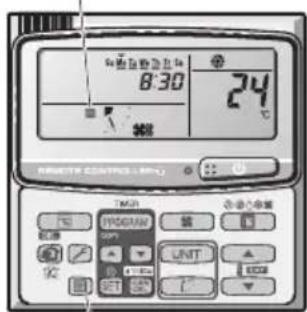
HdikatopnIbtpa
KhoNka c6poca qnIbTpap
CToPiHa IHOPMALIJI IPO IPOJYKT 142
3AXOJII BEE3NEKN 142
MICLIE BCTAHOBJIEHHRA 143
EJIeKTPuHIBIMoH 143
PABUNATEXHIKINBE3NEKN 144
IHΦOPMALI 146
BVKOPNCTAHH 147
PEYJIIOBAHHH HANPRMKV NOTOKY NOBITPA 149
HAJALITYBAHHHANPIMKY NOTOKYNOBITPRIJIKAIBKOX BHYTIUHIX 3A
DIOHOMOIO ONDHOI NUYIbTY INCTAHLIHORO KEPYBAHHA (JPOTOBOHO) 151
OCOBJIIBI IPRIMITKU 152
DOJRA TAOUHHEHH 152
NOWYK TA YCYHEHHH HECNPABHOCTE 154
NEPEBIPTE NEPED TUM, RK 3BEPTATNCA NO TEXHUY DONOMOY. 155
IOPADNIUOIO3AOUAdXEHHREJEKTPOEHEPII 155
CNEUINΦIKALI 172
IHΦOPMAUJI IPO IPOJyKT
KaO y BAC BNHKHyb npo6nem a6o nHTaHHCTOCOBHO KOHnuciohepa, Bam 3HaIO6nTbcN haBeDeHa daJI IHOpMaui. Moelb Ta cepiHi Hmepn BkazHo Ha Ta6nUci y HnxHi YaactnHi Kopnycy.
No modeni CepiHni No
Даразидааньня
Ampesa dnilepa
HomepTelepoHy

3AXOДиБE3NEKIN
Habehei dani cmmboJn, 0BnKOpncTOByoTbC B ciI Inctpkui 3 ekcnnyataui, 3actepiraOt b npO yMOBn, noteHciuHO He6e3neuHi dJI KOpncTyBaivB, o6cnyrobyoHoro nepcoHany nn pnpctpo:

3ACTEPEXEHHH
LcH CmB0J BnKOpNCTOByeTbCg DnA NO3HaueHH 3aRpO3NBUx CNTyauiy HHe63neuHXx DI, 0o MoKyTb npn3BeCTn Do cepno3HOro TpaBMyBaHHy Nc CmeptI IIOde.

TONEPEDEKHEHH
LcH CMBON BKNOPNCTOBcTbCnIaN
NO3NaeHHN 3arpo3JNBHX CNTyaCiI Nn
He63neuHx Di, 10 MoKyTb Pn3BecTn Do
TpabMycBaHH NIOdeA bO yKoDKeHH BnPo6y
Ym MaHa.
MICLE BCTAHOBJIEHH

3ACTEPEXEHHH
- PekomeHdyctbca, 06 BCTaHOBHeHHa boro KOHNIOhepa HaneXHM YHOM BnKohyBaIoc KbaJIiPikOBaHmN cneuaianCTAMN 3 yCTaHOBKn 3riDHO 3 iHcTpyKciHMM 3i BCTaHOBHeHH, 0o NoCTaAoiTbcpa3om i3 Bnpo6om.
- PpeB BCTaHOBJeHHAMnepeBipTe, Hn Hanpyra B Mepexi eNekTpOncTaHnY BAC yDOM a6o B ophi ci cnIBnaJaC i3 BkazaoHOn Ha TabnHi HanpyroIO.
Cni yHkata:
He BCTAHOBJIIOte ue KOHNIOHep y Micax, De HABHI BNAPOBByBaHHa6o NERKO3aMncti ra3n Ta B MICaX i3 dyxke BUCOKOBOBORictIO, HanpNKJaDy TENMIaX.
He BCTAHOBNIOTe ue KOHNIOHep y Micux, De HABHI 6'KTH, IO BUNPOMHOITb HAdmipHO BENKY KInbKiTb Tenna.
Ioo 3axnCTnKoHnioHep BiD 3HaHooKOPO3i, yHkaTe BCTaHOBneHH 3OBHIshBOO 6loKa B Mic4x, De Ha HbOro MOKJIbE pPme NOpAnJHH 6pN3OK COHOJ MOpcbKOI BOu a60 no6Jn3y MihepanbHnx Dkepe, De B nobITpi MiCtNTbc Cipka.
EJEKTPNCHIBMOMI

TONEPEJXEHHA
1.Yci npOTn MaIOb BiINOBiDaTn MiueBm eJeKtpoTeXHm npaBnam i HopMa. IpokOHcyIbTyIteCb 3i CBOIM dInepom a6o KBaJIicIKOBAHm eJeKtpnKOM 0do DetaleN.
2. Koxen npicpiMae 6yTu HaneKHM YHOM 3a3emJHn 3a donomoroKabeIO 3aemJHn a6o uepe3 dpotu mepexi eJeKTpOncTaHaHH.
3. Po60Tu 3 eJEnKtpnHmIM dpotaM MaIOT b NKoHbATnC KBaJIipikOBaHm eJEnKtpnKOM.
PNUMMITKA
Ioo6 po3irpiTn cnCTemy, JxepeNo xNBHeHH NoTpiHOb yBIMKHyTn npHaumHi 3a n'ATb (5) rOHN Do nooatky po60tn. 3aIIuwaTe dJxepeNo XNBHeHH YBIMKHEHM. BmukaiTe Ioro IInse ToDi, KOnn npncTpIi He BIKOPNCTOByBaTMetbCnpoTAROM TpNBanoro Yacy.
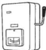
JKepeNo KnuBneHH
YBIMKHEHO
Ko KOHnueHep TpBann yac He BkOpncToBycBc, Bi'deHaTe NOro Bi dJxepena eJeKtpoeHepri, BmKHyBwn XNBleHHa BiNobiDnMM BmMkaem a6o BtTARHyBwn WTeNCenb i3 po3eTK. RaKo BmKHyTO oHN i3 6IokIB (OBIHIu H BYTpIuHi), BC8 CNTema He npauOBaTme.
Hikon He TopkaTecn npucTroIO BOIorIMpykam.
Hikon He BnKOpncToBnyTe Ta He 36epiraTe 6eH3n H iHsi IerKo3aMnCti ra3n Ta piDInn npuy i3 KOHNIOHePOM - ue dyxke He6e3neHo.
He BnKOpncToBnyTe npuJa y npMiuEHHax i3 nOteHuiNo Bn6yXoHe6e3neuHO aTMocpepoIO.
Lcien KOHnDIOHep He MaC BeHTnIATopAp dna 3a6bopy cBIXoro NOBITpy 3HaIBOPy. Y BInpaKky cactoro BVKOpNCTaHHB OOnHi KIMHaTI rA3OBHX n MacJHnXo obirpiBaiv, 0O NOrIIHaIOb BEINKy KJIbKICtB KICHO 3 nobITp, NotpioHo cacto BiIDKpNBAtn DBepi a6o BIKHa. IHaKwe, y KpaHix BnPaKaX, MoKe BHNKHyTu pN3NK 3aNyxn.
Длг КОЖНOrO npICrPoIO BnDIniTb OKpemy po3eTKy, loBVKOPNCTOBYBaTmEtcbaBNHrKoBO DЯ LcBOrO npICrPoHO; OndHocHo Ha OkpeMii LiHII MaIToB 6yTu nepeJb6aueHi MoXJIbICr bIdKnIOUHeHHeNEKrpoNOCtayHnA, ABTOMaTnHn 3anobixHnK Ta aBTOMaTnHn 3anobixHnK Ha BnnaDOK BNTOKy CTrpMy B3emLIO dNra 3axNcTy BiD nepeBaHTaXeHHa CTrpMOM.
Длг Кожного писчтоби ВдіпітБ okрему розетку; Odnhoасноу сдацioHaphi npobodci 3riДno 3 eJeKtpoTeXHiYHIMn npabuIamMu MaC 6yTu nepeDbaYeHo MOxJIbICtB NOBHOrO BiДКЛIOUHeHHa WIIaXOM pO3ipBaHHa KOHTaKTiHa BCIX NOLIOcax.
Длгзанбiraанн Hebe3neci, loMOKe BnHnKHyTN Hepe3 noIkoJxHRe H3OJIaII, npICTpI Ma6 6yTn 3a3emLeHn.
OuNTKa 3OBHIHbOTo Ta BHYpiHbOro 6IOKIB He NOBHHa BIKOHyBaTnC KOpNCTyBaUAMn. OUnCTKa MaE BIKOHyBaTnC aTbOPn3OBAHm DnJIePOM aOc CneuaJIcTOM.
Y BnnaKy 360bB pOBoTi cboTIO npNCTPOH He peMOHTyIte Ioro camOCTiHO. IaI peMOHTy npNCTPOH 3BepHiTcA do npOdaBua a6o cepBichoro ceHTpy.
BntiKaHHxOJIOaReHTy MoKe npu3BeCTn do noXoxeKi.
Uo6 yHnKHyTN He6e3neKn, o6OB'3KOBO BmkaTe KOHduioHep Ta BiDKIOuayTe XNBHeHHN, nepH HIX BnKOnyBaTn YNuEHHa 60 TexHcHe O6CnyroByBaHH.
Ypa3i He6e3neKn BiIDcHnAHTe KOHNIOHep BiDxKepeNa eNeKtpoeHepri, BmKHyBnXnBHeHHaBiNObiHMM Bmukayem a6o BnTARHyBnWTeNCelb i3 po3eTKn.
He BCTaBnIe nIbUi Ta iHusi npEMeTu y BHyTpIwHi i 3OBHIuH NIOKN KOHNIOHepa -DeTani, 0o OepeTaIOTbcra, MOKyTb 3aBdATn TpaBM.
Uo6 yHnKHyTn nepepiBaHHra Ta noKexi, He BIKOPNCOTByTe MoINcikOBaHm, 3'EDnhyBaIbHm, HeBn3HaueHm shHyp a60 nOIOBXyBaY.


3ACTEPEXEHHH
Припинить ВИКОРИСТОВУВАТИ ПИСТПЕ ПИ NOВI 6удьяков OЗнaki Нэштathою робTu/ HeсрпавнocTi I BИМiTb WTeNCEьну BИКу abO BIMKHiT bpeMnKaay YBIMKHeHry/BIMKHeHry i peMnKaay eJeKTPOXINBHeHry (pI3NK IOЯВи ДИМY/BИNHKeHну NOXeKi/ypaXeHry eJeKTpUHm CTPyMOM)
PππKJIaDi NHeWtTaTHoI pO6ToN/HeCnpaBHOcti
- YacTo CnpaBobyE nepemkae ELCB.
- 3Явбязэдаму.
3'RBNBCa HETINOBm yum a6o Biipauia npictpoIO.
I3 BHyTpuiHbOro 6Joka BuTikae BOda.
Bunka a6o ka6eIb eJIeKTpOxuBJeHHaTeNIIiHIMn, HIX 3BNUHaHO. - HEMOXNIBO perynIOBATn WBNDKICTb BEHTNJATOPa.
-Ппстпг НаянО ппиннг рбOTу, HabITь ркю BiH yBIMKHeHm B pO6Ou n peXm. - BeHTnIaTOp He 3yInHReTbCra, HabItb KOJI pOboOni peXIM BUMKHeHNI.
HeraHo 3B'axiTbc3 MiCueBm DnIepom dI npObeEHnTexHiChoro OScnyroByBaHHa/peMOHTy.

TONEPEDEKHEH
OblaanhaHH npn3naHcnoI nBn BkOpncTaHH eKcnepTaMn abo CneuJIbHO HauChENMI KOpNCyBaUAMn y KpaMHnucx,Ha niDnpmCmCTbax NERKOIpomncNoBOcti, y fcpMepcbKnx rocNoapCTbax, a TAKOX DnA KOMePuiHOr BO NKOpncCTAHH HeCneuJiaJIcTAMn.
He BmkaTe Ta He BmkaTe KOHduiohep nepemkaemdxepela XnBneHHa. KopucTytecKHOKNKOYbIMKHeHH-BMVKHeHH.
HiHOro He npntyIe I Do OTbOpny DnBnNycky nobitpr Ha 3OBHIuHbOmy 6LoQi. Lc Hebe3neUHO, OckInbKn BEHTNIrTOP oEepTaetbCn i3 BnCOKoo WBnDkictHO.
He TopkaTecb OTBpy dIa Bncykny nobitpr a6o roctpnx aniomhiEbx Inonacte 3OBHIshhoro 6loka. MoKJIne bopaneHHa.
Po3taoByte noxexHy cHraJIaIauTo Ta OTbIp dN BnIycky nobITpa HbIDCTahi npHaHmHi 1,5 M BiD pncTpOIO.
Lcien pncctpi He npn3naeHOn nBnKOpncTaHnO oc6aMn (y TOMy uNcni diTbMn) 3 o6mExeHmN cI3uHMMoXJINBOCTAMN, MOXJINBOCTAMN cPnHrTTra, PO3ymOBHM3dIOHOCTAMn a60 3 HeIOCTaTHim 6araKeM docBiy Hn 3HaNb. Taki OC6b MoKyTB KOpNCtYBaTncz mnpnlAOM IiNe iHaJrDM IIOJe, BiNDoIaJIbHNx 3a ixHIO 6e3neky, a6o nicra OTpmaHHN BiD Lnx IIOJe IHcTpKciu IooKOpcNTyBaHHn npnIaOM. Heo6XiHo npnrIgdaTn 3a diTbMn, 106 BOHn He rpaIncI 3 npncTroem.
He pobItb Tempepaty B KimHaTi 3aHaTOn Hn3bKOU cn BnCOKIO, AKNo TAM nepe6yBaKToB HeMOBJIraT a60 iHbJIiN.
He npTuynIte XoDiHi 6'ekTn Do KOKVXA BEHTUNIYTOPA.
MoxHa OTpMaTn TpaBMy, a npucTpI MoKe NOsKOJNTNcR.
He ciānTe Ta He nactynaiTe Ha npictpi. Bu mojete Bnactn.


3AYBAXEHHR
- IHOJI iID yac rpo3n MOKJINBa 3ynHka KOMnpecopa.
Ye He mexaHnHm noWKoJKeHHa. PnucTpi aBtOMaTuHo BiHOBIOc po60Ty uepe3 Kibka XBUNH.
- TekCT aHrIiNcBKOIO MOBOIO - ue opriHaI IHCTpyKci. TeKCT iHsIMM MOBaMn c nepeKnaIaOM opriHaIy IHCTpyKci.
Ha3Ba Ta aDpeca Bnpo6Hnka y Pocii Ta YkpaIHi
Ha3By Ta aadecy Bnpo6nka Bka3aHo Ha ynaKobu Ta nacnopTHi Ta6nui.

HaTnCHeHHaM Liei KHOJNKn npncTpiBmKaCTbCA i BmKNaCTbCra.
IДикaToppo6ToN:
IicnyyBIMKHeHH3aBiuyEtbcra Iicny BUMKHeHH 3raae
IhdkaTop po6oTu
Ihdkatop BMkaetbca, KOJI KOnDnioHep npaue.
Ihdkatop MroTntb y pa3i nomnuk a60 yBIMKHeHHa 3axCHOro npncToIO.
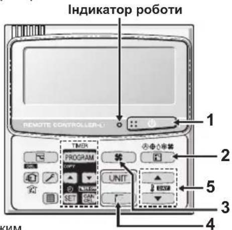
2. Khonka (Bn6ip pexmy)
3a donomoroio ziei KhoNkn MoXHa Bn6paTn peXIM.
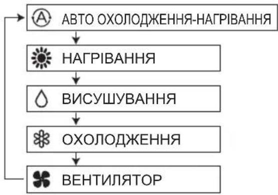
... Pekn m abTo oxoJOnOKeHH-HarpiBaHH Bn3Haaye pi3HnUo mix nonepedhbo HanaTobAHIO TemnepaTypoHO Ha NyIbTi DnCTaHuiHoro KepyBaHH i paKTuHoo Tempepatyo y npmiueHHI. Notim BIn ABTomatNo HO Bn6npaE peKm HarpiBaHHa OXoJOnOKeHH. (3dINCHOBATN KepyBaHH ABTomATuHHM HarpiBaHHa TM OXoJOnOKeHHaM dIra CnCTeMn 2WAY Ta mini VRF MoxHa, KOJI N KepyBaHH Ycima BHyTpIshHM 6IOKamn BV TOMy camOMY KOHTpyi OxonoKyBaHa 3diChHoetbcr y pexMI KepyBaHH rpyno).
3. Khonka (WBndkicb BeHTnnaTopa)
3MiHa WbNdkocti BcHTnIaTopa.
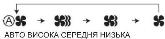
ПРИМITKA.
KoNn KhoNkny Bnu6opy peXmUy BCTaHOBneHO B noToxKeHHA BEHTUNTOP, Bu6paTu peXm ABTO HemOxKnBO.
4. Khonka (KoINBaHHHaHApMOK NOTOKY NOBITPRA)
HaTnCKaIte KhoNkY KOJINBaHnHaHnpA Mky NOTOKy NOBITpy DJIra BCTaHOBHeHHpeXIMy ABTomatNuHOrO KOJINBaHn HtOpKn Yn CnpAMyBaHn NOKITpy NiD NEBHm KYToM. (DeTaJIbHy IHopMaCiIO YHTaTe B pOzdiJI «PeryJIIOBaHn HaNPaMKy NOTOKy NOBITpy").
5. KhonknaHanaTuBaHHa TemnepaTpyn
3MiHa HanaaTbVaHnTeMnepaTpyn.
HaTnckaTe KhoNkH aHaIaHTyBaHHa TEmpePaTyP dIra BCTaHOBJIeHHa Notpi6HOi TEmpePaTyP.
KepyBaHHr rpynno
CTopoHn Bnycky Ta Bnycky nobITpa (BHyTpiHiN 6nok)
OuHyIe CTOpOHn BnCkY Ta BnCkY NOBITP BHyTpiHbOro 6Noka uIKoIO NInococa aO npToPAte ix HCTOIO cyHO TKaHHHO.
Haux qactnHex nHMn, cokpntaTecn TcHNO 3moeHO y BOi. Piaoc OunueHHCTOPOHBNycky NOBITpe 6ydbTe obepekhi, 06 He 3pywnI ONaTkn 3 MlC4.
BKA3IBKN 0OIO QIUEHHRA
- He BnKOpncToBnyTe DnA YnUeHn 6eH3nH, po3uHHNK OuOuSyUOuN Nopoouk.
BnKOpNCToByIe JnIe MmNbHn (pH7) nHeITpaNBn NObyTOBm MNIOy3ac6. - He BnKOpncToBvIe BoNy, TempepaTypa kOJI nepeBnUye 40°C.
IOPADN
-ДЯ ONTUMANbHOI pOBoTn i 3MeHWeHHcNoXuBaHH eHepri perynapHo YnctbTeФInTp.
3NTaHb ceoHHoro orIy 3BepTaTeCra Do Hai6nKHO rnaepa.
AJIOMIHIEBA IJIACTNHA
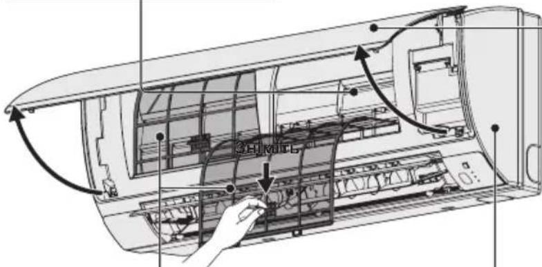
NEPEHNAHEJIb
3HimAHn HpeDhboi NaHeJI
PiHIMiMb i NotrHiB nepedHO naHeB, 063HrTn II.
JIeKo NOMnTe Ta BnCyuItb.
3aKpmbHnnepeHbOi naHeJI
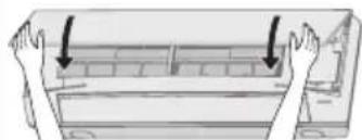
Ha 6nBa KInu ipeepHb0i NaHei, uo6 HaHHIO II 3aipikcyBatN.
NOBITPJIHΦINbTPN
- Ynctitb noBiprHi fInbTpN KOxHn DBA TnKHi.
- JIeRKO NOMNITc/CNOIOCHiTb fJbTpN BOIOO dna 3an06irAHn noWkoDxKeHHIO XHBoI NOBepxHi.
- Dópe Bucyitb φiBtpn B Tini NODani BiD BORHOH INPpIMNX COHryHIN PpomeHIB.
-3amihtb nookxkeHH fInbtp.
BHYTPIUSHIN BJOK
JERKo npotpiB 6IOK M'RAKO cyXO raHApKOHO.
Hanpknad: nybT dncTaHnHO KepyBaHH 3 TaImePOM
DorJ3a noBITpHmΦinbTpom
PekomeHdyetbcra YnCTNTN NOBITPAHn FInbTp, KOJHa
DncnneI 3'ABnEETBCaIHnKaUaIc (FInbTp). DnA
3a6e3neueHH ONTUMaJIbHOI pOBoTI peryJrpho YnCTbTe
FInbTp BiN Nnny Cu nnnm Knpy, He3aJeXHo BiD CTahy FInbTpA.
■Пиячишня
- NocntBnNIOItpHNI pIbTp, BCTaHOItb Ioro Ha Micce. BCTaHOblIOte pIbTp Ha Micce, BuKohyOCh Onncahi BnIe dIy 3BOPOTHomY npAky.
- Hatncihb KhoNky cKaDaHHa pinbtpa. IHnkaTOp 1pipbTp) Ha dncnnei 3rache.
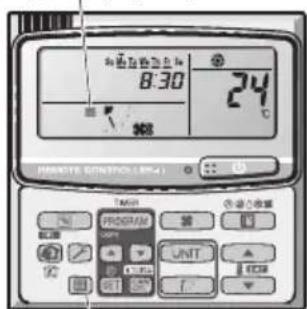
Izhikatopfihbtpa
KhoNka cKnDaHnHa qInbTa
NOWyK TA YCYHEHHA HECnPABHOCTeI
Kaio Bau KOHnIOHe HpaOe HaneKHM YHOM, BkOHaIte HabeEHI Hxue di, nepu Hix 3BepTaTcna NO TexHiHy donomory. Kaio ce He Donomorno, 3b'AXITbc3i CBOIM MicueBm DnJepom a6o cepBichm UeHTpom.
BHYTPLHII BLOK
Lampu pengoperasian:
Wall Mounted (K2 type)
| Model Name S-15MK2E5A S-22MK2E5A | S-28MK2E5A S-36MK2E5A | |||||
| Power Source | 220 / 230 / 240 V ~50 / 60 Hz | |||||
| Cooling capacity | kW 1.5 | 2.2 2.8 3.6 | ||||
| BTU / h 5 | 100 7,500 9,600 12,300 | |||||
| Heating capacity | kW 1.7 | 2.5 3.2 4.2 | ||||
| BTU / h 5 | 800 8,500 10,900 14 | 300 | ||||
| Sound Pressure level | High dB(A) | 34 36 37 40 | ||||
| Medium dB(A) | 32 33 34 | 36 | ||||
| Low dB(A) | 29 29 29 29 | |||||
| Sound Power level | High dB(A) | 49 51 52 55 | ||||
| Medium dB(A) | 47 48 49 | 51 | ||||
| Low dB(A) | 44 44 44 44 | |||||
| Unit Dimensions (H×W×D) | mm | 290×870×214 | 290×870×214 | 290×870×214 | 290×870×214 | |
| Net weight | kg | 9 | 9 | 9 | 9 | |
4-Way Cassette 60x60 (Y2 type)
| Model Name S-15MY2E5A S-22MY2E5A | S-28MY2E5A S-36MY2E5A | |||||
| Power Source | 220 / 230 / 240 V ~50 / 60 Hz | |||||
| Cooling capacity | kW 1.5 | 2.2 2.8 3.6 | ||||
| BTU / h 5 | 100 7,500 9,600 12,300 | |||||
| Heating capacity | kW 1.7 | 2.5 3.2 4.2 | ||||
| BTU / h 5 | 800 8,500 10,900 14,300 | |||||
| Sound Pressure level (C/H) | High dB(A) | 34/34 35/35 35/35 36/36 | ||||
| Medium dB(A) | 31/31 31/31 31/31 32/32 | |||||
| Low dB(A) | 25/25 25/25 25/25 26/26 | |||||
| Sound Power level (C/H) | High dB(A) | 49/49 50/50 50/50 51/51 | ||||
| Medium dB(A) | 46/46 46/46 46/46 47/47 | |||||
| Low dB(A) | 40/40 40/40 40/40 41/41 | |||||
| Unit Dimensions (H×W×D)* | mm | 319×700×700*1 | 319×700×700*1 | 319×700×700*1 | 319×700×700*1 | |
| 319×625×625*2 | 319×625×625*2 | 319×625×625*2 | 319×625×625*2 | |||
| Net weight* | kg | 20.4 | 20.4 | 20.4 | 20.4 | |
| Model Name S-45MY2E5A S-56MY2E5A | ||||
| Power Source | 220 / 230 / 240 V ~50 / 60 Hz | |||
| Cooling capacity | kW 4.5 | 5.6 | ||
| BTU / h | 15,400 19,100 | |||
| Heating capacity | kW 5.0 | 6.3 | ||
| BTU / h | 17,100 21,500 | |||
| Sound Pressure level (C/H) | High dB(A) | 38/38 40/40 | ||
| Medium dB(A) | 34/34 37/37 | |||
| Low dB(A) | 28/28 34/34 | |||
| Sound Power level (C/H) | High dB(A) | 53/53 55/55 | ||
| Medium dB(A) | 49/49 52/52 | |||
| Low dB(A) | 43/43 49/49 | |||
| Unit Dimensions (H×W×D)* | mm | 319×700×700*1319×625×625*2 | 319×700×700*1319×625×625*2 | |
| Net weight* | kg | 20.4 | 20.4 | |
- Values include the dimension and weight of an optional ceiling panel.
- Panel Model No. CZ-KPY3A
*2 Panel Model No. CZ-KPY3B
SPECIFICATIONS
■ Mini (LE1 type) (Single-phase)
| Model Name U-4LE1E5 U-5LE1E5 U-6LE1E5 | |||
| Power Source | 220 / 230 / 240 V, ~50 Hz | ||
| Cooling capacity | kW 12.1 | 14.0 15.5 | |
| BTU / h 41 | 1,300 47,800 52,900 | ||
| Heating capacity | kW 12.5 | 16.0 18.0 | |
| BTU / h 42 | 2,700 54,600 61,400 | ||
| Sound Pressure Level (C/H) | dB(A) 50 | 52 51/53 52/55 | |
| Sound Power Level (C/H) | dB(A) 68 | 70 69/71 70/73 | |
| Unit Dimensions (H×W×D) | mm 133 | 30×940×340 | |
| Net weight | kg | 104 104 104 | |
■ Mini (LE1 type) (3-phase)
| Model Name U-4LE1E8 U-5LE1E8 | U-6LE1E8 | |||
| Power Source | 380 / 400 /415 V, 3N ~50 Hz | |||
| Cooling capacity | kW 12.1 | 14.0 15.5 | ||
| BTU / h 41 | 1,300 47,800 52,900 | |||
| Heating capacity | kW 12.5 | 16.0 18.0 | ||
| BTU / h 42 | 2,700 54,600 61,400 | |||
| Sound Pressure Level (C/H) | dB(A) 50 | 52 51/53 52/55 | ||
| Sound Power Level (C/H) | dB(A) 68 | 70 69/71 70/73 | ||
| Unit Dimensions (H×W×D) | mm 133 | 30×940×340 | ||
| Net weight | kg | 103 103 103 | 3 | |
SPECIFICATIONS
2WAY (ME1 type)
| Model Name U-8ME1E81 U-10ME1E81 U-12ME1E81 U-14ME1E81 U-16ME1E81 | |||||
| Power Source | 380 / 400 / 415 V, 3N ~50 Hz | ||||
| Cooling capacity | kW 22.4 | 28.0 33.5 40.0 45.0 | |||
| BTU / h 76 | 6,500 95,600 114,300 136,500 153,600 | ||||
| Heating capacity | kW 25.0 | 31.5 37.5 45.0 50.0 | |||
| BTU / h 85 | 5,300 107,500 128,000 153,600 170,600 | ||||
| Sound Pressure level dB(A) | 56.5 | 9.0 61.0 62.0 62.0 | |||
| Sound Power level dB(A) | 71.0 73.5 | 75.5 76.5 76.5 | |||
| Unit Dimensions (H×W×D) | mm | 758×770×930 | 1758×770×930 | 1758×770×930 | 1758×1000×930 |
| Net weight | kg | 234 | 234 | 281 | 309 |
| Model Name | U-18ME1E81 U | 20ME1E81 | |
| Power Source | 380 / 400 / 415 V, 3N ~ 50 Hz | ||
| Cooling capacity | kW 50.0 | 56.0 | |
| BTU / h | 170,600 191, | 100 | |
| Heating capacity | kW 56.0 | 63.0 | |
| BTU / h | 191,100 215, | 000 | |
| Sound Pressure level dB(A) | 60.0 | 63.0 | |
| Sound Power level dB(A) | 74.5 | 77.5 | |
| Unit Dimensions (H×W×D) | mm 175 | 58×1540×930 | 175 |
| 58×1540×930 | |||
| Net weight | kg | 421 | 421 |
SPECIFICATIONS
3WAY (MF2 type)
| Model Name U-8MF2E8 U-10MF2E8 U-12MF2E8 U-14MF2E8 | ||||
| Power Source | 380 / 400 / 415 V, 3N ~50 Hz | |||
| Cooling capacity | kW 22.4 | 28.0 33.5 40.0 | ||
| BTU / h 76 | 6,500 95,600 114,300 136,500 | |||
| Heating capacity | kW 25.0 | 31.5 37.5 45.0 | ||
| BTU / h 85 | 300 107,500 128,000 153,600 | |||
| Sound Pressure level dB(A) | 57.0 | 9.0 61.0 62.0 | ||
| Sound Power level dB(A) | 71.5 73.5 | 75.5 76.5 | ||
| Unit Dimensions (H×W×D) | mm | 1758×1000×930 | 1758×1000×930 | 1758×1000×930 |
| Net weight | kg | 269 | 269 | 314 |
| Model Name | U-16MF2E8 | |
| Power Source | 380/400/415V, 3N~50Hz | |
| Cooling capacity | kW 45.0 | |
| BTU / h | 153,600 | |
| Heating capacity | kW 50.0 | |
| BTU / h | 170,600 | |
| Sound Pressure level | dB(A) 62.0 | |
| Sound Power level | dB(A) 76.5 | |
| Unit Dimensions (H×W×D) | mm | 1758×1000×930 |
| Net weight | kg | 322 |
SPECIFICATIONS
CARACTERISTIQUES / ESPECIFICACIONES / TECHNISCHE DATEN / SPECIFICHE / SPECIFICATIE / ESPECIFCAOES / IPOAIAPAEZ / CTIELIMOKALIM
| English Français Espanol Deutsch | |||
| 4-Way Cassette 60x60 (Y2 type) | Cassette 4 voies 60x60 (Type Y2) | Cassette de 4 vías 60x60 (esto Y2) | 4-Weg Kassette 60 x 60 (Typ Y2) |
| Wall Mounted (K2 type) Monté au mur (Type K2) Montado en pared (esto K2) Wandmontage (Typ K2) | |||
| Mini (LE1 type) Mini (Type LE1) Mini (esto LE1) Mini (Typ LE1) | |||
| 2WAY(ME1 type) 2WAY (Type ME1) 2WAY (esto ME1) | 2WAY (typ ME1) | 2WAY (Typ ME1) | |
| 3WAY(MF2 type) | 3WAY (Type MF2) | 3WAY (esto MF2) | 3WAY (Typ MF2) |
| English Italiano | Nederland | Português | |
| 4-Way Cassette 60x60 (Y2 type) | A cassetta a 4 vie 60x60 (tipó Y2) | 4-weg cassette 60x60 (type Y2) | Cassete de 4 vias 60x60 (Tipó Y2) |
| Wall Mounted (K2 type) | Con montaggio a parete (tipó K2) | Wandmodel (K2) | Montagem na parede (Tipó K2) |
| Mini (LE1 type) Mini (tipó LE1) Mini | (type LE1) Mini (Tipó LE1) | ||
| 2WAY(ME1 type) 2WAY (tipó ME1) | 2WAY (type ME1) | 2WAY (Tipó ME1) | |
| 3WAY(MF2 type) | 3WAY (tipó MF2) | 3WAY (type MF2) | 3WAY (Tipó MF2) |
Declaration of Conformity with the requirements of the e-waste (Management and Handling) Rules, 2011
(adopted by Noti cation S.O.1035(E) of Ministry of Environment and Forests)
The Product is in conformity with the requirements of Rule 13 of the e-waste Rules.
The content of hazardous substance with the exemption of the applications listed in SCHEDULE II of the e-waste Rules:
- Lead (Pb) - not over 0.1% by weight;
- Cadmium (Cd) – not over 0.01% by weight;
- Mercury (Hg) - not over 0.1% by weight;
- Hexavalent chromium (Cr^6+) - not over 0.1% by weight;
- Polybrominated biphenyls (PBBs) – not over 0.1% by weight;
- Polybrominated diphenyl ethers (PBDEs) – not over 0.1% by weight.
For the purpose of recycling to facilitate effective utilization of resources, please return this product to a nearby authorized collection center, registered dismantler or recycler, or Panasonic service center when disposing of this product.
Please see the Panasonic website for further information on collection centers, etc.
http://www.panasonic.com/in/corporate/sustainability/panasonic-india-i-re cycle-program.html
Panasonic Corporation
Website: http://panasonic.net/
© Panasonic Corporation 2014
Printed in Malaysia
Authorized representative in EU
Panasonic Testing Centre
Panasonic Marketing Europe GmbH
Winsberging 15, 22525 Hamburg, Germany
F569612
BE1213-10914