
PGDK - Air-conditioner DAIKIN - Free user manual and instructions
Find the device manual for free PGDK DAIKIN in PDF.
| Product type | Pump group with mixer for heating |
| Brand | Daikin |
| Model | PGDK |
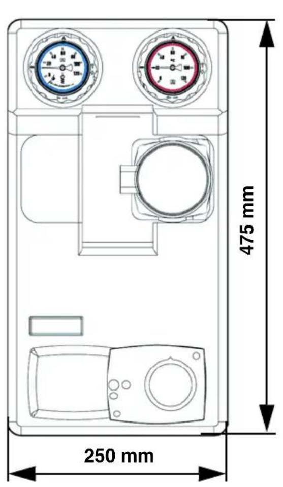
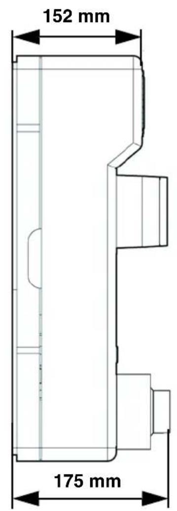
| Dimensions (L x H x D) | 250 x 475 x 152 mm |
| Weight (with mixer) | 5.5 kg |
| Weight (without mixer) | 7.2 kg |
| Maximum service pressure | 10 bar |
| Maximum fluid temperature | 110 °C |
| Body material | Brass |
| Insulation material | Polypropylene (EPP) |
| Boiler connection | R1 1/2 |
| Heating circuit connection | Rp1 |
| Total flow coefficient (Kvs) | 4.8 m³/h |
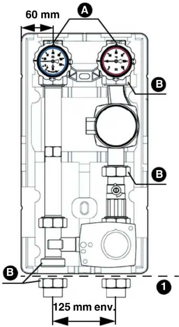
| Center distance | 125 mm |
| Authorized fluids | Heating water according to VDI 2035, water-glycol mixture max 20% |
| Main functions | Circulation, mixing, temperature control, isolation by ball valves |
| Maintenance | Visual inspection and monthly leak test |
| Cleaning | Flushing of pipes before installation recommended |
| Safety | Double insulation, overpressure protection, DANGER/WARNING instructions |
| Spare parts | Replaceable circulation pump, temperature sensors optional |
| Repairability | Pump replacement without draining the system thanks to the return valve |
| Warranty | According to general sales conditions at www.daikin.com |
Frequently Asked Questions - PGDK DAIKIN
User questions about PGDK DAIKIN
0 question about this device. Answer the ones you know or ask your own.
Ask a new question about this device
Download the instructions for your Air-conditioner in PDF format for free! Find your manual PGDK - DAIKIN and take your electronic device back in hand. On this page are published all the documents necessary for the use of your device. PGDK by DAIKIN.
USER MANUAL PGDK DAIKIN
Read manual before use!
Observe all safety information!
Keep manual for future use!
English
1 About these operating instructions
These operating instructions describe the pump assembly with and without mixer (also referred to as "product" in these operating instructions).
These operating instructions are part of the product.
- You may only use the product if you have fully read and understood these operating instructions.
- Verify that these operating instructions are always accessible for any type of work performed on or with the product.
- Pass these operating instructions as well as all other product-related documents on to all owners of the product.
- If you feel that these operating instructions contain errors, inconsistencies, ambiguities or other issues, contact the manufacturer prior to using the product.
There operating instructions are protected by copyright and may only be used as provided for by the corresponding copyright legislation. We reserve the right to modifications.
The manufacturer shall not be liable in any form whatsoever for direct or consequential damage resulting from failure to observe these operating instructions or from failure to comply with directives, regulations and standards and any other statutory requirements applicable at the installation site of the product.
2 Information on safety
2.1 Safety messages and hazard categories
These operating instructions contain safety messages to alert you to potential hazards and risks. In addition to the instructions provided in these operating instructions, you must comply with all directives, standards and safety regulations applicable at the installation site of the product. Verify that you are familiar with all directives, standards and safety regulations and ensure compliance with them prior to using the product.
Safety messages in these operating instructions are highlighted with warning symbols and warning words. Depending on the severity of a hazard, the safety messages are classified according to different hazard categories.
DANGER
DANGER indicates a hazardous situation, which, if not avoided, will result in death or serious injury.

WARNING
WARNING indicates a potentially hazardous situation, which, if not avoided, can result in serious injury or equipment damage.
NOTICE
NOTICE indicates a hazardous situation, which, if not avoided, can result in equipment damage.
In addition, the following symbols are used in these operating instructions:

This is the general safety alert symbol. It alerts to injury hazards or equipment damage. Comply with all safety instructions in conjunction with this symbol to help avoid possible death, injury or equipment damage.
This symbol alerts to hazardous electrical voltage. If this symbol is used in a safety message, there is a hazard of electric shock.
2.2 Intended use
This product may only be used to circulate the following liquids in intrinsically safe, sealed, thermal heating systems:
Heating circuit water as per VDI 2035
Water/glycol mixtures with a maximum admixture of 20%
Any use other than the application explicitly permitted in these operating instructions is not permitted and causes hazards.
Verify that the product is suitable for the application planned by you prior to using the product. In doing so, take into account at least the following:
- All directives, standards and safety regulations applicable at the installation site of the product
- All conditions and data specified for the product
- The conditions of the planned application
In addition, perform a risk assessment in view of the planned application, according to an approved risk assessment method, and implement the appropriate safety measures, based on the results of the risk assessment. Take into account the consequences of installing or integrating the product into a system or a plant.
When using the product, perform all work and all other activities in conjunction with the product in compliance with the conditions specified in the operating instructions and on the nameplate, as well as with all directives, standards and safety regulations applicable at the installation site of the product
2.3 Predictable incorrect application
The product must never be used in the following cases and for the following purposes:
- Use with drinking water
- Use with adherent, corrosive or flammable fluids
- Operation in systems with temperatures exceeding 110^ (for example, solar systems)
2.4 Qualification of personnel
Only appropriately trained persons who are familiar with and understand the contents of these operating instructions and all other pertinent product documentation are authorized to work on and with this product.
These persons must have sufficient technical training, knowledge and experience and be able to foresee and detect potential hazards that may be caused by using the product
All persons working on and with the product must be fully familiar with all directives, standards and safety regulations that must be observed for performing such work.
2.5 Personal protective equipment.
Always wear the required personal protective equipment. When performing work on and with the product, take into account that hazards may be present at the installation site which do not directly result from the product itself.
2.6 Modifications to the product
Only perform work on and with the product which is explicitly described in these operating instructions. Do not make any modifications to the product which are not described in these operating instructions.
3 Transport and storage
The product may be damaged as a result of improper transport or storage.
NOTICE
DAMAGE TO THE PRODUCT
- Verify compliance with the specified ambient conditions during transport or storage of the product.
- Use the original packaging when transporting the product.
- Store the product in a clean and dry environment.
- Verify that the product is protected against shocks and impact during transport and storage.
Failure to follow these instructions can result in equipment damage.
4 Product description
The product is a pre-assembled, tightness-tested and heat-insulated pump assembly.
The universal insulation allows for the installation of virtually any standard circulation pump (with G1^1/2 connection and a length of 180 mm) without major reworking of the insulation.
The second ball valve in the return line lets you replace the pump without draining the system.
In addition, the system is modular so that the flow line can be mounted at the left or the right side. Optional temperature probes 6mm can be mounted to all ball valves.
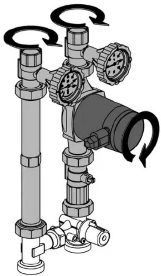
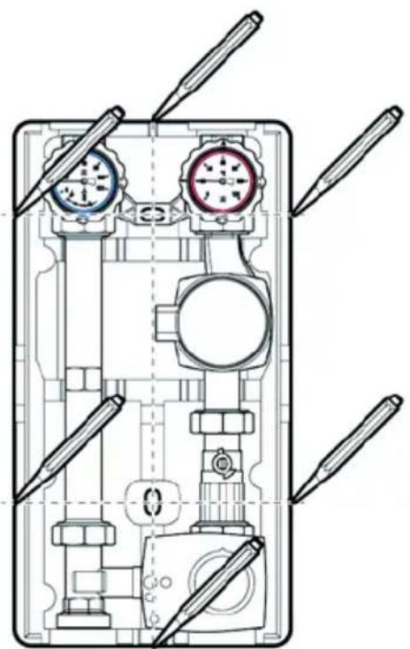
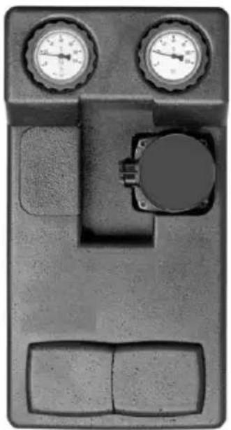
4.1 Overview
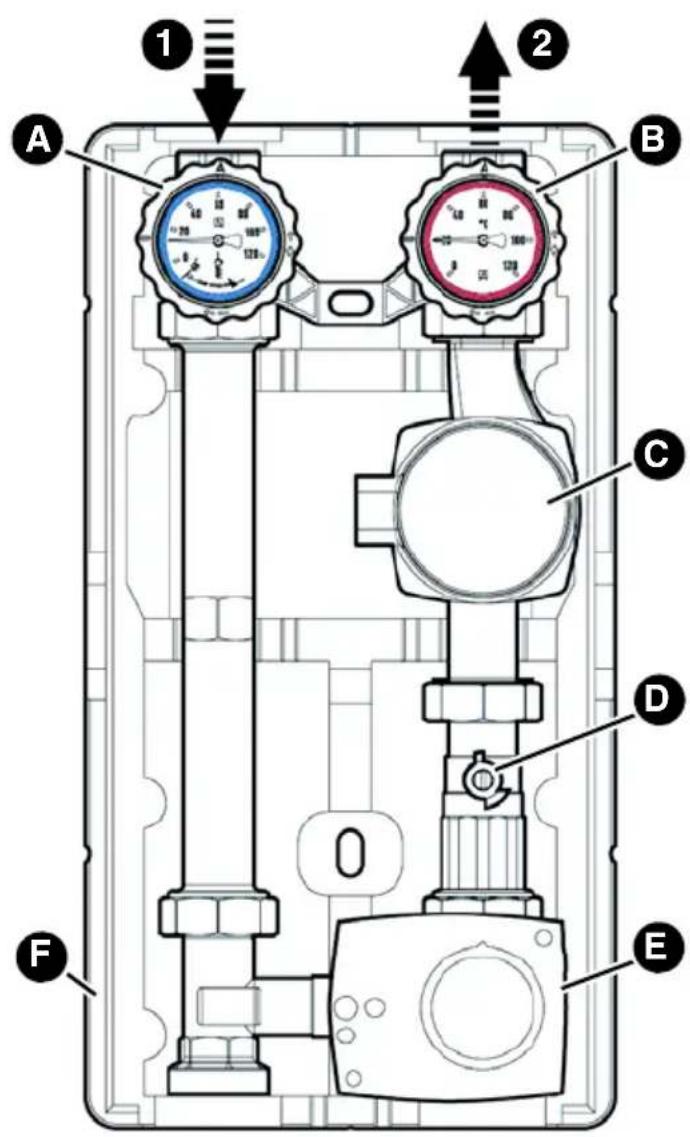
Fig. 1: PrimoTherm® components
- Return
- Flow
A. Ball valve, can be shut off, with thermometer blue and gravity brake
B. Ball valve, can be shut off, with thermometer red
C. Circulation pump (various manufacturers)
D. Ball valve
E. 3-way mixer with actuator
F. Insulation
4.2 Versions
The variable insulation can be used for applications with flow at the left and flow at the right.
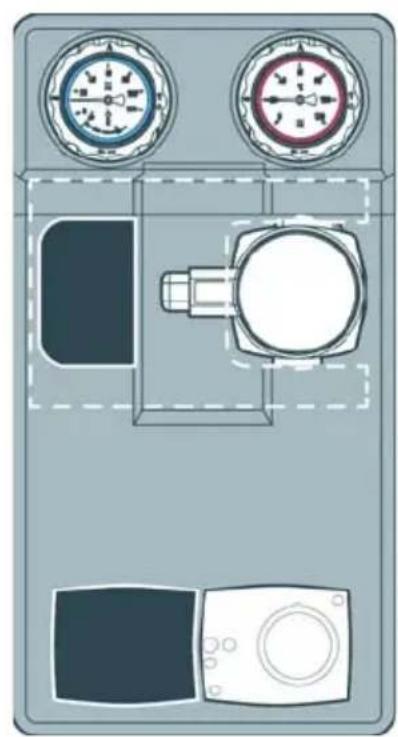
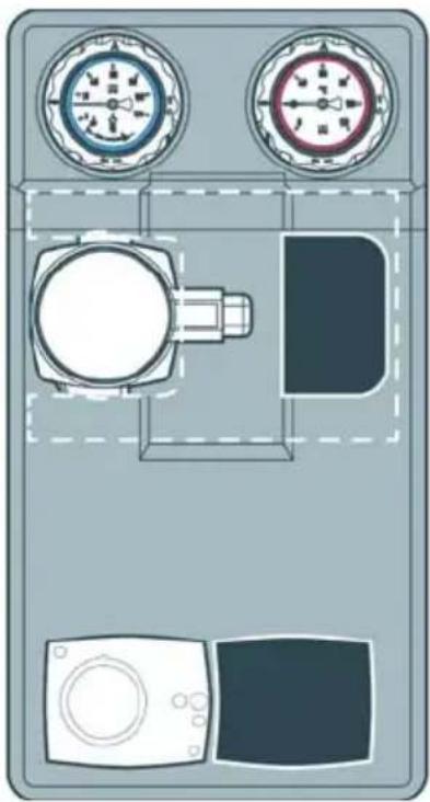
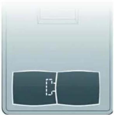
Fig. 2: Flow right (left figure)
Fig. 3: Flow left (centre figure)
Fig. 4: Without actuator (right figure)
4.3 Dimensions and connections
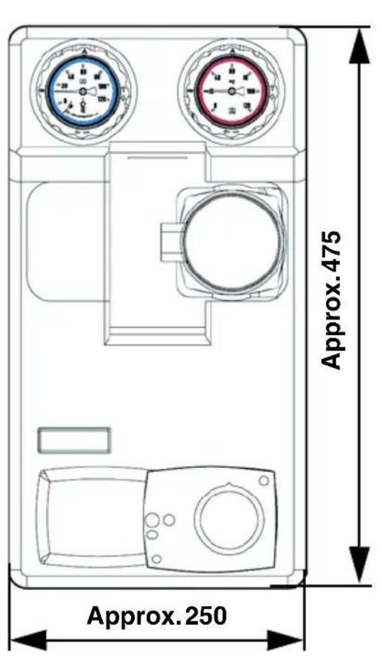
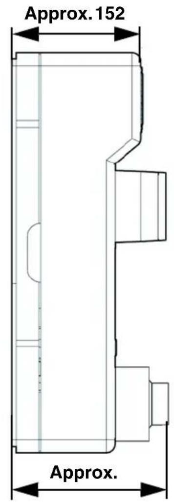
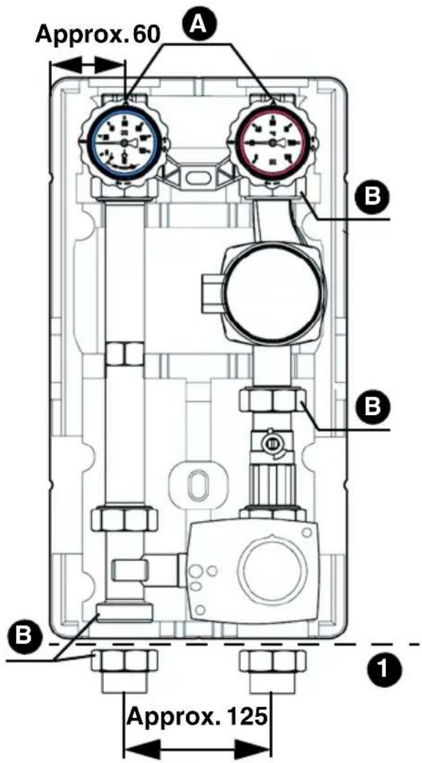
A. G1
B. G1 12
4.4 Approvals, conformities, certifications
See operating instructions of the manufacturer of the circulation pump for versions with circulation pump.
4.5 Technical specifications
| Parameter Value | |
| General specifications | |
| Dimensions with insulation (W x H x D) | 250 x 475 x 152 mm |
| Weight Approx. 5.5 kg with mixer | Approx. 7.2 kg without mixer |
| Material of fittings Brass | |
| Insulation material Polypropylene EPP | |
| System pressure Max. 10 bar | (observe maximum pressure of circulation pump used) |
| Axis distance 125 mm | |
| System connections Boiler R1 | 1/2Heating circuit Rp1 |
| Flow coefficient Kvs 4.8 m | 3/h |
| Operating temperature range | |
| Medium Max. 110 °C | |
| Pressure loss | |
| Flow line Flow coefficient Kvs = 6.9 | 3/h |
| Return line Flow coefficient Kvs = 6.7 | 3/h |
| Total: Flow coefficient Kvs = 4.8 m | 3/h |
5 Mounting

WARNING
BURNS CAUSED BY HOT LIQUID
Water in heating systems is under high pressure and can have temperatures of more than 100^ .
- Verify that the heating water has cooled down before opening the system and mounting the product.
Failure to follow these instructions can result in death, serious injury or equipment damage.
5.1 Preparing mounting
Verify that the product is mounted in such a way that no external forces can act on the components after it has been installed.
Verify that the product is not overheated by welding or soldering work performed on the system.
- Install the product after completion of such welding or soldering work.
Verify that the nominal pressure of the product corresponds to the specification value of the system.
Verify that the liquid in the system and the application area of the product are compatible.
Verify that the pipes are thoroughly flushed prior to installation of the product.
- Impurities such as weld beads, hemp or metal chips cause leaks of the product.
5.1.1 Interchanging flow/return
Unless otherwise specified, all information in these operating instructions relates to the installation type "flow right".
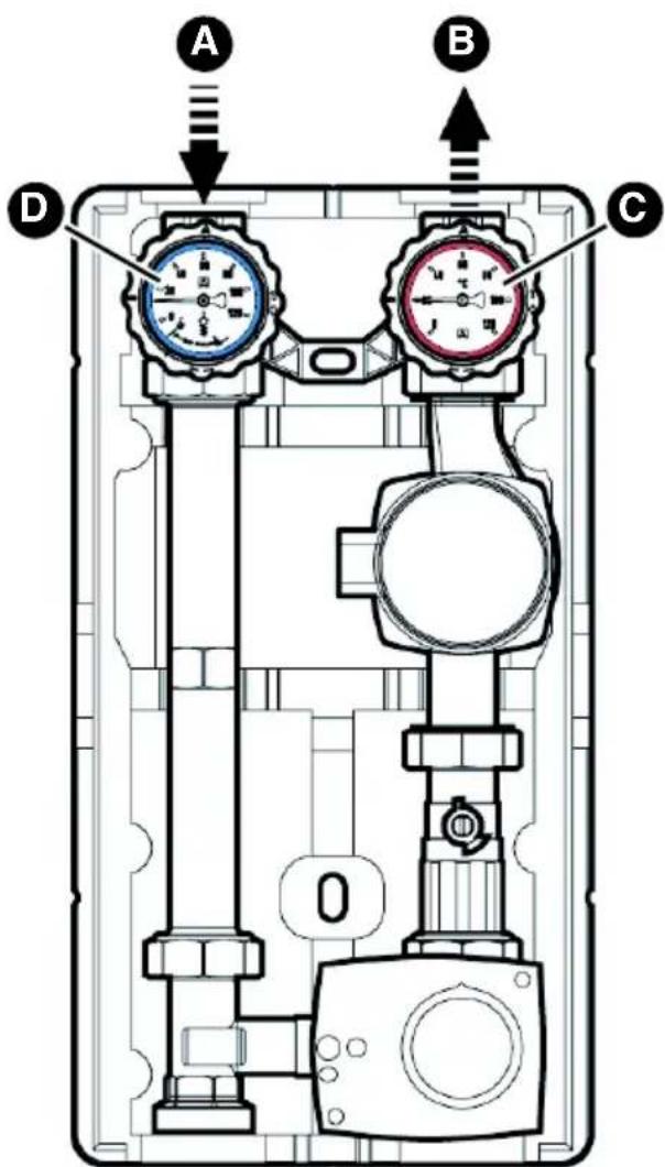
Fig. 5: Flow right (condition as supplied)
A. Return
B. Flow
C. Red thermometer ball valve
D. Blue thermometer ball valve
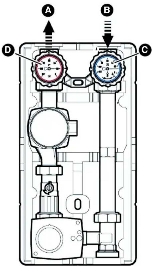
Fig. 6: Flow left
A. Flow
B. Return
C. Blue thermometer ball valve
D. Red thermometer ball valve
- Interchange left and right lines.
- Turn the pump head.
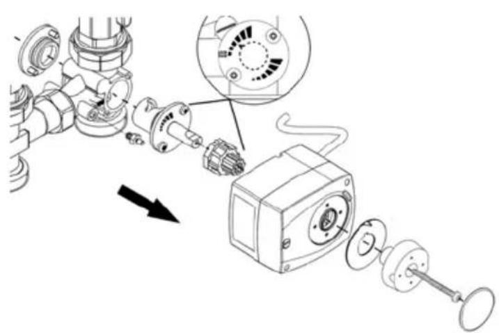
- Change the actuator. - Flow right
- Uninstall the actuator.
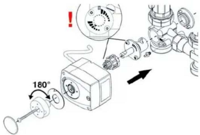
-
Re-install the actuator. - Flow left
-
Fit the upper insulation.
5.1.2 Mounting the temperature probe (optional)
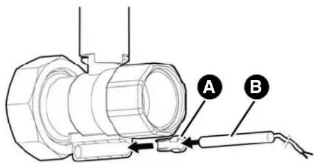
Depending on the type of the temperature probe (B), it may be necessary to shorten the ferrule (A).
5.2 Mounting the product
5.2.1 Mounting the product to a module manifold
NOTICE
MECHANICAL LOADS AND STRESS
- Verify that the product is not subjected to mechanical loads and stress when connecting the product.
- If necessary, install a corrugated pipe compensator to compensate for mechanical stress or tension.
Failure to follow these instructions can result in equipment damage.
- Remove the insulation.
- Screw the pump assembly to module manifold.
- Screw the pipes of the heating circuit to the top connections (no mechanical stress).
- Fit the complete insulation.
5.2.2 Wall mounting
NOTICE
MECHANICAL LOADS AND STRESS
- Verify that the product is not subjected to mechanical loads and stress when mounting the product to the wall.
Failure to follow these instructions can result in equipment damage.
- Remove the upper insulation.
- Hold the product to the wall and align it with a level.
- Draw six marks.
- Interconnect the opposing marks.
- Drill holes (010mm) at the position of the two centre marks.
- Insert the enclosed dowels.
- Screw the long hanger bolt into the top hole.
- Screw the short hanger bolt into the bottom hole.
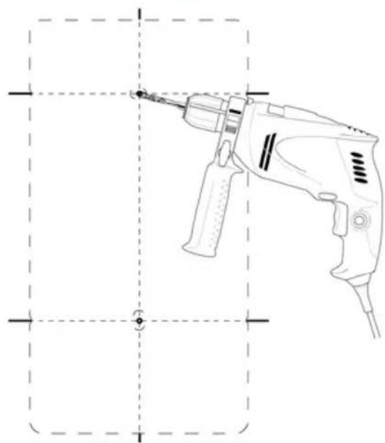
- Fit the product with the bottom insulation and secure it with a washer and a nut.
- Connect the pipes of the heating circuit to the connections of the fittings (no mechanical stress).
11.Fit the upper insulation.
5.3 Electrical connection
DANGER
ELECTRIC SHOCK
- Verify that the degree of protection against electric shock (protection class, double insulation) is not reduced by the type of electrical installation.
Failure to follow these instructions will result in death or serious injury.
DANGER
ELECTRIC SHOCK CAUSED BY LIVE PARTS
- Disconnect the mains voltage supply before performing the work and ensure that it cannot be switched on.
- Verify that no hazards can be caused by electrically conductive objects or media.
Failure to follow these instructions will result in death or serious injury.
- Connect the circulation pump and the actuator in accordance with the instructions of the manufacturer.
6 Commissioning
6.1 Commissioning the product
Verify that the thermometer ball valves are in 0^ setting.
- Perform a pressure test.
- Check all screwed connections for tightness.
- Set to ball valves to 45^ position for filling of the system.
- Fill the system and apply pressure.
- Set the ball valves to 0^ position.
6.1.1 Thermometer ball valves
| Thermometer ball valves | |||
| 0° N | Normal operation: Gravity brake active | ||
| 90° | Maintenance: Ball valve closed | ||
| 45° | Commissioning, filling, venting, flushing: Both ends open (gravity brake not active) | ||
7 Operation
Proper operation is only possible if the thermometer ball valves and the ball valves are open (0° setting, see chapter "Thermometer ball valves").
8 Maintenance
8.1 Maintenance intervals
| When Activity | |
| Monthly Perform a visual inspection of the heating system and verify tightness. | |
| If required Replace the circulation pump. | |
8.2 Maintenance activities
DANGER
ELECTRIC SHOCK CAUSED BY LIVE PARTS
- Disconnect the mains voltage supply before performing the work and ensure that it cannot be switched on.
Failure to follow these instructions will result in death or serious injury.
8.2.1 Replacing a defective circulation pump
- Close the red thermometer ball valve and the ball valve in the pump line (90° setting).
- Replace the circulation pump (see instructions of the manufacturer of the pump).
- Open the thermometer ball valve and the ball valve (0^ setting).
9 Troubleshooting
Any malfunctions that cannot be removed by means of the measures described in this chapter may only be repaired by the manufacturer.
Also observe the corresponding instructions of the manufacturer in the case of malfunctions of the circulation pump or the actuator.
| Problem Possible reason | Repair | |
| Noise in the system Air | in the system Vent the system | |
| Circulation pump not properly adjusted | Verify correct adjustment of the circulation pump | |
| Other malfunctions - Contact | AFRISO | service hotline |
10 Decommissioning, disposal
Dispose of the product in compliance with all applicable directives, standards and safety regulations.
Electronic components must not be disposed of together with the normal household waste.
- Disconnect the product from mains.
- Dismount the product (see chapter "Mounting", reverse sequence of steps).
- Dispose of the product.
11 Returning the device
Get in touch with us before returning your product.
12 Warranty
See our terms and conditions at www.daikin.com or your purchase contract for information on warranty.


156077 PGDK
156075 PGMK
Deutsch
4.3 Dimensions et raccordements
A. G1
B. G1 12
BESCHADIGING VAN HET PRODUCT
- Too0eTnOe To npoiov mvo apou ooknpoov aotc oepyaoiec.