
Radius 200L - Microphone ALTO - Free user manual and instructions
Find the device manual for free Radius 200L ALTO in PDF.
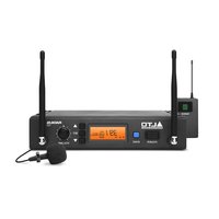
| Product Type | UHF Wireless Lavalier Microphone System |
| Brand | Alto |
| Model | Radius 200L |
| Frequency Band | UHF 520–937.5 MHz (depending on region) |
| Microphone Type | Lavalier microphone with bodypack transmitter |
| Receiver | Dual UHF True Diversity Receiver with two BNC antennas |
| Display | Backlit LCD display: frequency, channel, RF/AF levels, mute |
| Receiver Power Supply | 12 V, 1 A power adapter (center positive) |
| Transmitter Power Supply | 2 AA batteries (alkaline recommended) |
| Estimated Battery Life | Approximately 8 hours with alkaline batteries |
| Range | Up to 100 m (328 ft) line-of-sight |
| Audio Outputs | Balanced XLR (line/mic level) and unbalanced 6.35 mm |
| Line/Mic Selector | Yes, on rear panel of receiver |
| Squelch Control | Yes, adjustable to reduce background noise |
| Functions | Auto scan, button sync, manual/preset modes |
| Box Contents | Receiver, lavalier mic, bodypack transmitter, rack mount kit, 6.35 mm audio cable, 2 BNC antennas, power adapter, 2 AA batteries, user guide |
| Receiver Dimensions (approx.) | 48 x 4.4 x 15 cm (19 inches, 1U) |
| Receiver Weight (approx.) | 2 kg |
| Care and Cleaning | Clean with a soft dry cloth; avoid moisture; store in a dry place |
| Safety | Do not expose to water or extreme temperatures; use only the supplied adapter |
| Spare Parts and Repairability | Contact Alto Professional support or visit altoprofessional.com |
Frequently Asked Questions - Radius 200L ALTO
User questions about Radius 200L ALTO
0 question about this device. Answer the ones you know or ask your own.
Ask a new question about this device
Download the instructions for your Microphone in PDF format for free! Find your manual Radius 200L - ALTO and take your electronic device back in hand. On this page are published all the documents necessary for the use of your device. Radius 200L by ALTO.
USER MANUAL Radius 200L ALTO
User Guide (English)
Introduction
Features
All-in-one, easy-to-use wireless microphone system for the most demanding professional applications
Dual-antenna/dual-receiver True Diversity design for mission-critical, dropout-free operation
UHF band operation (520-937.5 MHz), regionally selected
- Receiver includes a high-visibility back-lit LCD display: Displays RF frequency and channel, AF and RF signal levels and other critical functions
- Radius 200: Hand-held condenser vocal microphone transmitter with integrated LCD display
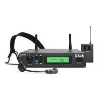
- Radius 200H: High-quality headset microphone and wireless belt-pack transmitter
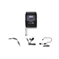
Radius 200L: High-quality lavalier/lapel microphone with included clip and wireless belt-pack transmitter
- Radius 200M: Wireless belt-pack transmitter and 1/4" (6.35mm) instrument cable
- Single-button scan feature for quickly identifying the optimal operating frequency
- Sync function automatically synchronizes transmitter and receiver frequency
- Squelch control for maximum clarity and dynamic range
- Front-panel rotary volume control
Balanced XLR and unbalanced 1 / 4 (6.35 mm) mic- or line-level outputs
Box Contents
Radius 200
Radius 200 Receiver
Radius HHT Condenser Microphone Transmitter
Rackmount and Coupling Brackets (screws included)
1/4" (6.35mm) Unbalanced Audio Cable (3 feet / 1 meter)
2 BNC antennas
Power Adapter
2 AA Batteries
User Guide
Safety & Warranty Manual
Radius 200H
Radius 200 Receiver
Radius HSM Headset Microphone Transmitter
Radius BPT Wireless Belt-Pack Transmitter
Rackmount and Coupling Brackets (screws included)
1/4" (6.35mm) Unbalanced Audio Cable (3 feet / 1 meter)
2 BNC antennas
Power Adapter
2 AA Batteries
User Guide
Safety & Warranty Manual
Radius 200L
Radius 200 Receiver
Radius LVM Lavalier Microphone Transmitter
Radius BPT Wireless Belt-Pack Transmitter
Rackmount and Coupling Brackets (screws included)
1/4" (6.35mm) Unbalanced Audio Cable (3 feet / 1 meter)
2 BNC antennas
Power Adapter
2 AA Batteries
User Guide
Safety & Warranty Manual
Radius 200M
Radius 200 Receiver
Radius BPT Wireless Belt-Pack Transmitter
Rackmount and Coupling Brackets (screws included)
1/4" (6.35mm) Instrument Adapter Cable
1/4" (6.35mm) Unbalanced Audio Cable (3 feet / 1 meter)
2 BNC antennas
Power Adapter
2 AA Batteries
User Guide
Safety & Warranty Manual
Support
For the latest information about this product (system requirements, compatibility information, etc.) and product registration, visit altoprofessional.com.
Important Safety Precautions
Please note: Alto Professional and inMusic are not responsible for the use of its products on the misuse of this information for any purpose. Alto Professional and inMusic are not responsible for the misuse of its products caused by avoiding compliance with inspection and maintenance procedures. Please also refer to the included safety and warranty manual for more information.
Cables
Make sure your cables are out of the way of performers, production crew, and audience so they will not trip over them.
Sound Level
Permanent hearing loss may be caused by exposure to extremely high noise levels. The U.S. Occupational Safety and Health Administration (OSHA) has specified permissible exposures to certain noise levels. According to OSHA, exposure to high sound pressure levels (SPL) in excess of these limits may result in hearing loss. When using equipment capable of generating high SPL, use hearing protection while such equipment is under operation.
| Hours per day | SPL (dB) | Example | |
| 8 | 90 | Small | gig |
| 6 | 92 | Train | train |
| 4 | 95 | Subway | train |
| 3 97 High level | desktop monitors | ||
| 2 | 100 | Classical | music |
| 1.5 | 102 | Riveting | machine |
| 1 | 105 | Machine | factory |
| 0.50 | 110 | Airport | |
| 0.25 or less 115 | Rock concert | ||
Features
Transmitter
Your Radius 200 includes one of the following transmitter systems:
- Radius 200: a hand-held condenser vocal microphone transmitter
- Radius 200H: a headset microphone and wireless belt-pack transmitter
- Radius 200L: a lavalier microphone and wireless belt-pack transmitter
- Radius 200M: a 1/4 (6.35mm) instrument adapter cable and wireless belt-pack transmitter
Condenser Microphone Transmitter (Radius 200)
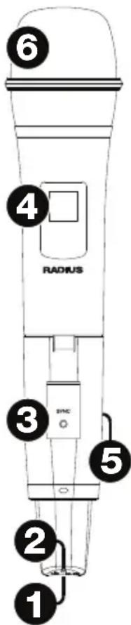
- Power/Mute Button: Press this button for 4 seconds to power the transmitter on or off. When the transmitter is on, press this button briefly to mute or unmute the microphone.
- Power/Mute LED: This light indicates the power or mute status:
Red light: The transmitter is on.
- Flashing red light: The transmitter is low on battery power.
- Blue light: The transmitter is muted.
- Flashing blue light: The transmitter is muted and low on battery power.
- Sync Button: Press this button to synchronize the transmitter with the receiver. See Operation to learn more.
- Display: This display shows the current channel and battery power level.
- Battery Compartment (not pictured): Insert 2 AA batteries into the compartment. Make sure the polarities of the batteries (+ and -) are correct.
- Grille: This mesh protects the microphone capsule and reduces noise from air and breath.
Belt-Pack Transmitter (for Radius 200H headset, Radius 200L lavalier microphone, or Radius 200M instrument cable)


- Power/Mute Button: Press this button for 2 seconds to power the transmitter on or off. Press this button briefly to mute or unmute the transmitter.
- Power/Mute LED: This light indicates the power or mute status:
Red light: The transmitter is on.
- Flashing red light: The transmitter is low on battery power.
- Blue light: The transmitter is muted.
- Flashing blue light: The transmitter is muted and low on battery power.
- Sync Button: Press this button to synchronize the transmitter with the receiver. See Operation to learn more.
- Display: This display shows the current channel and battery power level.
- Battery Compartment (not pictured): Insert 2 AA batteries into this compartment. Make sure the polarities of the batteries (+ and -) are correct.
- Microphone/Instrument Input (mini-XLR): Connect the included microphone or instrument cable to this input.
- Gain Selector: Use this switch to set the gain of the audio input to 10 dB, 0 dB, or -10 dB. For instruments with passive pickups, we recommend setting this to -10 dB. For instruments with active pickups, you may want to set this to 0 dB or -10 dB.
Receiver
Front Panel

- Power Button: Press this button to power the receiver on or off.
- Display: This display shows the current channel, frequency, and other settings. See Display for more information.
- Up/Down ( ) : Press one of these buttons to select the different modes (Manual, Autoscan, Preset). When searching for channels, press one of these buttons to move to the next-highest or next-lowest channel, respectively.
- Sync: Press this button to synchronize the receiver with the transmitter. See Operation to learn more.
- Set: Press this button to confirm your mode selection (Manual, Autoscan, Preset) or to set the current channel. See Operation to learn more.
- Volume Knob: Turn this knob to adjust the receiver's output level.
Display

- Manual: This indicator appears when the receiver is in Manual Mode, where you can select the channel manually. Use the Up/Down buttons to cycle between the different modes.
- Scan: This indicator appears when the receiver is in Autoscan Mode, where the receiver automatically selects the channel with the clearest and strongest reception.
- Preset: This indicator appears when the receiver is in Preset Mode, where you can select a Preset group of channels rather than having to scan the entire frequency band.
- Sync: This indicator appears when the transmitter and receiver are synchronized.
- GP (P1, P2, P3, P4): This is the current Preset group.
- CH (1-8): This is the current Preset Channel.
- CH (region-specific): This is the current channel number. The number of available channels depends on your region.
- Freq: This is the current frequency in MHz.
- Mute: This indicator appears when the audio signal is muted.
- RF: This meter shows the current level of reception between the transmitter and receiver.
- AF: This meter shows the current audio signal level sent from the receiver's audio outputs.
Rear Panel

- Antenna Terminal: Connect the included antennae to these terminals.
- Audio Output (XLR): Use a standard XLR cable to connect this balanced output to your guitar amplifier, mixer, PA system, etc.
- Audio Output (1/4" / 6.35 mm): Use a standard 1/4" (6.35 mm) cable to connect this unbalanced output to your mixer, PA system, etc.
- Line/Mic Selector: Use this switch to select whether the signal from the receiver's output is line-level or microphone-level. Set this switch to Line if you are connecting it to a balanced line-level input (e.g., a mixer's XLR or 1/4" TRS input) or an instrument amplifier's low-impedance active instrument input. Set this switch to Mic if you are connecting it to an instrument amplifier's high-impedance instrument-level input.
- Squelch: Turn this knob to adjust the noise floor level.
- Power Input: Use the included power adapter (12 V, 1 A, center positive) to connect this input to your power source.
Operation
To set up and use your Radius 200, follow the steps in this chapter in order. If you are setting up a system using multiple receiver-transmitter pairs, set up each pair one at a time, and keep each pair powered on as you set up others.
1. Set Up the Receiver
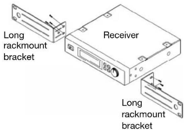
Optional: Connect Rackmount Pieces and/or Antennas
To use two receivers in a standard 19" rack, use the included rackmount brackets, coupling brackets, and screws.
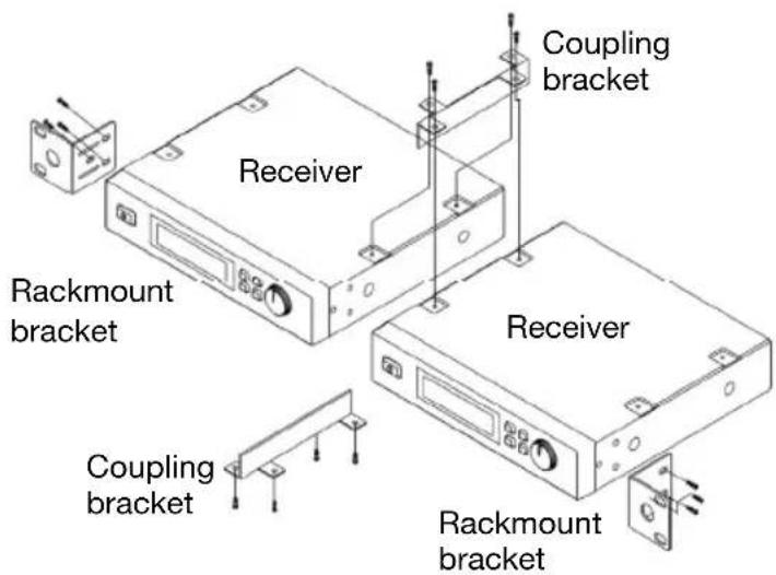
To use one receiver in a standard 19" rack, use two long rackmount brackets (sold separately) and screws.
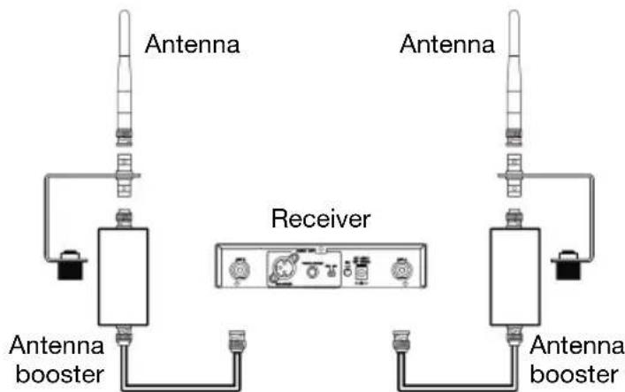
We highly recommend using the included antennas to improve and strengthen reception.
You can also use an antenna booster (sold separately) to further enhance the signal.
Set Up the Receiver's Connections, Mode, and Channel
- Use the included power adapter to connect the receiver's power input to your power source. The receiver will power on automatically.
- Use a standard XLR cable or 1/4 (6.35mm) to connect one of the receiver's audio outputs to your mixer or amplifier system. Do not use both audio outputs at the same time; this can result in signal loss or increased noise.
-
Set the Line/Mic Selector to the appropriate setting:
-
Set this switch to Line if you are connecting it to a balanced line-level input (e.g., a mixer's XLR or 1/4" (6.35mm) TRS input) or an instrument amplifier's low-impedance active instrument input.
-
Set this switch to Mic if you are connecting it to an instrument amplifier's high-impedance instrument-level input.
-
Set the receiver's channel using one of the following methods:
- Manual Mode
Important: Do not place two or more transmitters within range of the receiver when selecting a channel. Also, keep the transmitter at least 3 feet (1 meter) away from the receiver.
i. Use the receiver's Up or Down buttons to select Manual Mode. (You must press and hold each button for approximately 1 second to switch to the next mode.)
ii. Press and hold the Set button for approximately 1 second. The display's numbers will flash.
iii. Use the Up/Down buttons to select a channel.
iv. Press the Set button to lock the reception to that channel.
- Autoscan Mode
Important: If you are setting up a system using multiple receiver-transmitter pairs, keep each pair powered on as you set up others. This will prevent each pair from automatically selecting the same channel.
i. Use the receiver's Up or Down buttons to select Autoscan Mode (Auto). (You must press and hold each button for approximately 1 second to switch to the next mode.)
ii. Press and hold the Set button for approximately 1 second. The display's numbers will flash.
iii. Press the Up or Down button once. The receiver will automatically scan frequencies and select the first channel with strong, clear reception.
iv. Press the Set button to lock the reception to that channel.
- Preset Mode
i. Use the receiver's Up or Down buttons to select Preset Mode. (You must press and hold each button for approximately 1 second to switch to the next mode.)
ii. Press and hold the Set button for approximately 1 second. The display's numbers will flash.
iii. Use the Up/Down buttons to select a Preset group (P1, P2, P3, or P4).
iv. Press the Set button to lock the reception to that Preset group.
v. Use the Up/Down buttons to select a channel in that Preset group.
vi. Press the Set button to lock the reception to a channel in that Preset group.
Important: If there is any interference on the current Preset group's channels, repeat Steps iii-vi.
2. Set Up the Transmitter
Condenser Vocal Microphone Transmitter:
- Remove the transmitter's battery compartment cover and insert 2 AA batteries into the compartment. Make sure the polarities of the batteries (+ and -) are correct.
- Reattach battery compartment cover to the transmitter.
- Press the transmitter's Power Button for 4 seconds to power the transmitter on or off.
Wireless Belt-Pack Transmitter:
- Remove the transmitter's battery compartment door and insert 2 AA batteries into the compartment. Make sure the polarities of the batteries (+ and -) are correct.
- Press the transmitter's Power Button for 2 seconds to power the transmitter on or off.
3. Synchronize the Receiver and Transmitter
- Make sure the receiver and transmitter are within 3 feet (1 meter) from each other and powered on.
- Press and hold the Sync button on the transmitter until Sync flashes in the receiver's display.
- Press the Sync button on the receiver.
4. Adjust Your Levels and Settings
Gain Level: If you are using a wireless belt-pack transmitter, set its Gain Selector to 10 dB, 0 dB, or -10 dB to set the gain of the audio input.
Volume Level: Use the receiver's Volume Knob to set the audio signal level sent from the receiver's audio output to your mixer or amplifier system.
Squelch Level: Use the Squelch Knob to adjust the noise floor level, minimizing background or ambient noise during silent moments. Higher settings allow for greater noise reduction and dynamic range, but a setting that's too high can cause intentionally quieter sounds to be silenced along with the noise. Be sure to experiment with different settings to find an optimal balance.
Troubleshooting
Problem
The receiver does not produce any sound.
Solution
Make sure the receiver's power adapter is properly connected to the power input and a power source.
Make sure the transmitter's batteries are properly inserted and that their polarities (+) and (-) are correct.
Make sure the transmitter and receiver are set to the same frequency.
Make sure the receiver's audio output is properly connected to your mixer, amplifier system, etc.
Make sure the receiver and transmitter are within 328 feet (100 meters) and have a clear line of sight. Also, make sure the receiver is not immediately near any metal objects or devices that could cause RF interference (other wireless systems, TVs, radio, etc.).
Lower the setting of the receiver's Squelch knob.
There is audible interference in the transmission.
Make sure the receiver and transmitter are within 328 feet (100 meters) and have a clear line of sight. Also, make sure the receiver is not immediately near any metal objects or devices that could cause RF interference (other wireless systems, TVs, radio, etc.).
Make sure the receiver's antennae are properly attached to its antenna terminals.
If you are using multiple transmitter-receiver pairs, make sure the pairs are not using the same or adjacent frequencies.
The signal is distorted. Make sure the receiver is not immediately near any metal objects or devices that could cause RF interference (other wireless systems, TVs, radio, etc.).
Lower the setting of the receiver's Volume knob.
Technical Specifications
Hand-held condenser vocal microphone transmitter included with Radius 200.
Headset microphone and wireless belt-pack transmitter included with Radius 200H.
Lavalier/lapel microphone and wireless belt-pack transmitter included with Radius 200L.
1/4" (6.35mm) instrument adapter cable and wireless belt-pack transmitter included with Radius 200M.
Specifications are subject to change without notice.
Receiver
| UHF Band Operation | 520-937.5 MHz (region-specific) |
| Oscillator | PLL Synthesized |
| Frequency Stability | ±0.005% |
| Modulation | FM |
| Transmission Range | 328 feet / 100 meters |
| Signal-to-Noise Ratio | >100 dB (at 20 KHz deviation and 60 dBμV antenna input |
| Image & Spurious Rejection | 80 dB minimum |
| Receiving Sensitivity | At 2 uV over 52 dB/A SNR |
| Selectivity | >50 dB |
| AF Response | 80 Hz - 18 KHz |
| THD | <1% (at 1 KHz) |
| IF Frequency | 1st: 243.95 MHz / 2nd: 10.7 MHz |
| Dynamic Range | >100 dB |
| Tone Signal | 32.768 KHz |
| Audio Output 1 balanced XLR | 1 unbalanced 1/4" (6.35mm) |
| Display | High-visibility back-lit LCD with RF and AF meters |
| Power | Supply: 12 V, 1 A, center positive (adapter included) Consumption: 520 mA ±10 mA |
| Case | Half 19" EIA-rack metal case |
| Dimensions (width x depth x height) | 7.9" x 7.2" x 1.7" 20.0 cm x 18.3 cm x 4.2 cm |
| Weight | 2.1 lbs. 1.0 kg |
Transmitters
| UHF Band Operation | 520-937.5 MHz (region-specific) |
| Channel Selection | Synchronization with receiver |
| RF Power Output | 10 mW (maximum) |
| Oscillator | PLL Synthesized |
| Frequency Stability | ±0.005% |
| Deviation | ±20 KHz with limiting compressor |
| Spurious Emission | >60 dB below carrier frequency |
| THD | <1% (at 1 KHz) |
| Tone Signal | 32.768 KHz |
| Display | Hand-Held 2Migribharagent LCD Belt-Pack Transmitter: 2-digit 7-segment LCD |
| Power Hand-Held Microphone: 2.4 VDC (1.2V via 2 AA batteries) Belt-Pack Transmitter: 3 VDC (1.5V via 2 AA batteries) Consumption: 120 mA ±10 mA | |
| Dimensions (width x depth x height) | Hand-Held Microphone: 2.0" x 2.0" x 10.2" / 5.2 cm x 5.2 cm x 26.0 cm Headset Microphone: 1.5" x 0.5" x 0.5" / 3.8 cm x 1.3 cm x 1.3 cm Lavalier Microphone: 1.0" x 0.25" x 0.25" / 2.5 cm x 0.6 cm x 0.6 cm Belt-Pack Transmitter: 2.6" x 3.8" x 0.9" / 6.5 cm x 9.7 cm x 2.4 cm |
| Weight | Hand-Held Microphone: 0.5 lbs. / 0.2 kg Headset Microphone: 0.2 lbs. / 0.1 kg Lavalier Microphone: 0.1 lbs. / 0.05 kg Belt-Pack Transmitter: 0.2 lbs. / 0.1 kg |
Trademarks and Licenses
Alto Professional is a trademark of inMusic Brands, Inc., registered in the U.S. and other countries. All other product or company names are trademarks or registered trademarks of their respective owners.
altoprofessional.com
- User Guide (English)
- Introduction
- Features
- Box Contents
- Radius 200
- Radius 200H
- Radius 200L
- Radius 200M
- Support
- Important Safety Precautions
- Cables
- Sound Level
- Transmitter
- Condenser Microphone Transmitter (Radius 200)
- Receiver
- Front Panel
- Display
- Rear Panel
- Operation
- Set Up the Receiver
- Optional: Connect Rackmount Pieces and/or Antennas
- Set Up the Receiver's Connections, Mode, and Channel
- - Manual Mode
- - Autoscan Mode
- - Preset Mode
- Set Up the Transmitter
- Condenser Vocal Microphone Transmitter:
- Wireless Belt-Pack Transmitter:
- Synchronize the Receiver and Transmitter
- Adjust Your Levels and Settings
- Troubleshooting
- Problem
- Solution
- Technical Specifications
- Trademarks and Licenses
- altoprofessional.com
Brand : ALTO
Model : Radius 200L
Category : Microphone