MPKTRV3 - Other camera accessories SONY - Free user manual and instructions
Find the device manual for free MPKTRV3 SONY in PDF.
User questions about MPKTRV3 SONY
0 question about this device. Answer the ones you know or ask your own.
Ask a new question about this device
Download the instructions for your Other camera accessories in PDF format for free! Find your manual MPKTRV3 - SONY and take your electronic device back in hand. On this page are published all the documents necessary for the use of your device. MPKTRV3 by SONY.
USER MANUAL MPKTRV3 SONY
Operating Instructions ____ EN
Mode d'emploi F
Checking supplied accessories 6
Preparing 7
1 Preparing the adaptor 7
2 Preparing the video camera recorder 9
3 Attaching the video camera recorder to the marine pack.... 11
Recording 14
When the LEAK lamp flashes 15
Removing the video camera recorder 16
Note on O-ring 18
Underwater recording 20
Labeling parts and controls 21
Specifications 22
Features
- The MPK-TRV3 marine pack allows the following 8 mm video camera recorders to be used underwater.
CCD-TR1*/TR3*/TR8*/TR311*/TR330/TR403/TR413*/TR414*/TR420/TR440/TR490/TR506*/TR507*/TR555*/TR590/TR910*/TR940*/TR2200*/TR2300*/TR3000*/TR3300*/TR1E*/TR3E*/TR8E*/TR18E*/TR311E*/TR330E/TR340E/TR401E/TR402E/TR410E/TR411E*/TR412E*/TR420E/TR440E/TR490E/TR501E*/TR502E*/TR503E*/TR506E*/TR510E/TR511E*/TR512E*/TR520E/TR555E*/TR590E/TR610E*/TR620E*/TR640E*/TR710E*/TR720E*/TR730E*/TR740E*/TR760E*/TR810E*/TR820E*/TR825E*/TR840E*/TR845E*/TR910E*/TR920E*/TR1100E*/TR2200E*/TR2300E*/TR3000E*/TR3100E*/TR3200E*/TR3300E*/TR3400E*
TRV11/TRV12/TRV15*/TRV21/TRV25*/TRV30/TRV31*/TRV34*/TRV35*/TRV40/TRV41*/TRV44*/TRV51*/TRV65*/TRV70/TRV75*/TRV91*/TRV94*/TRV95*/TRV101*/TRV3E*/TRV10E/TRV11E/TRV12E/TRV13E*/TRV14E*/TRV15E*/TRV21E/TRV23E*/TRV24E*/TRV30E/TRV31E*/TRV35E*/TRV40E/TRV41E*/TRV44E*/TRV45E*/TRV51E*/TRV54E*/TRV55E*/TRV56E*/TRV60E/TRV61E*/TRV64E*/TRV65E*/TRV69E*/TRV70E/TRV81E*/TRV89E*/TRV91E*/TRV94E*/TRV95E*/TRV99E*/TRV101E*/TRV300E*
- Recording at a depth of 75 meters (246 feet) is possible.
-
The following operation can be performed underwater.
-
Power on/off
- Auto focusing on/off (models marked with *)
- Recording start/stop
- Power zooming
We recommend you use a wide-conversion lens (not supplied) when using the marine pack.

This mark indicates that this product is a genuine accessory for Sony video products. When purchasing Sony video products, Sony recommends that you purchase accessories with this “GENUINE VIDEO ACCESSORIES” mark.
On the video camera recorder
Take care not to expose the equipment to salty air. Do not drip water on the equipment.
- Do not open the marine pack while at sea or at the seaside. Preparations such as installing and checking the equipment should be made in a place with low humidity and no salty air.
- When a video camera recorder is used near the sea for a long time, we recommend that it is checked periodically by a Sony dealer.
- If the equipment becomes wet, take it immediately to the nearest Sony dealer for preventive maintenance.
On the video camera recorder power source
We recommend that you use battery packs with a large capacity. However, in some cases battery packs NP-99/4500/F930/F950 cannot be attached to the video camera recorder.
On the marine pack
- If you open and join the front and rear shells in a place with high temperature and high humidity, moisture condensation may occur when you put the marine pack in the water, causing the front glass to fog.
- The waterproof integrity of the marine pack is maintained by the O-ring, and the groove and surface where it touches. Be especially careful not to damage or deform that area. For details, see “Note on the O-ring” (page 18).
- Do not leave the marine pack under direct sunlight for a long period of time, otherwise the temperature in the marine pack may rise and the equipment inside may be damaged. If you cannot avoid leaving the marine pack under direct sunlight, be sure to cover the marine pack with a towel or other protection.
- Do not throw the marine pack into the water. Lower it gently into the water.
- Whenever you pick up the marine pack, handle the grip. If the underwater video light (not supplied) is attached to the marine pack, do not handle the underwater video light's arm.
On recording underwater
- Check that the equipment operates correctly and there is no water leak at a depth of about one meter (3 feet) before you dive deeper.
- Be sure to follow the safety rules for diving, such as diving period and depth.
- Remove the bubbles from the outside of the front glass.
Sony does not accept liability for damage to the video camera recorder, battery, etc. in the marine pack or for the loss of prerecorded material if water leak caused by incorrect operation occurs.
On maintenance
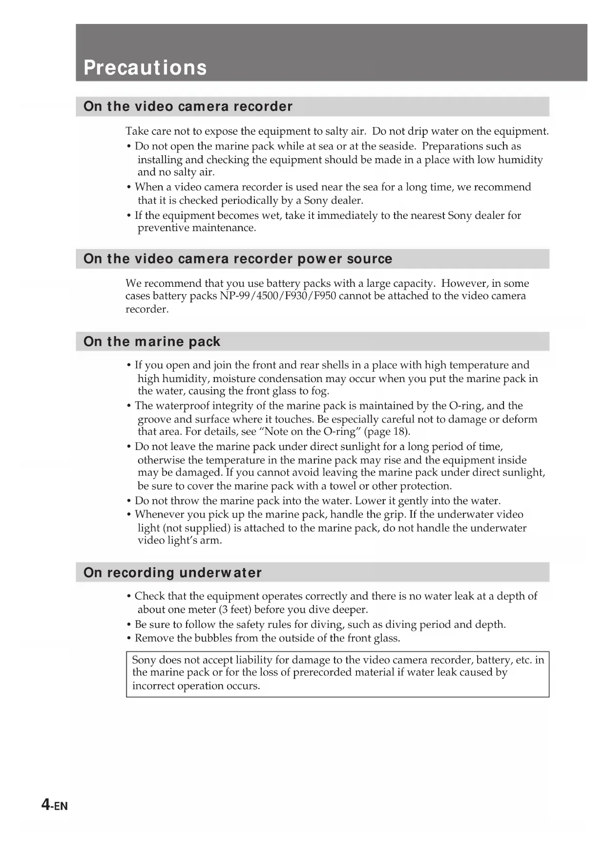
After recording in the sea, submerge the marine pack with the buckles tightly fastened in fresh water for a while to remove the sea water. Then rinse it with fresh water and wipe it with a soft cloth.
- Every time you use the marine pack and the video camera recorder underwater, clean the video camera recorder and the inside of the marine pack with a dry soft cloth. Do not use any type of solvent, such as alcohol or benzine for cleaning, as this may damage the finish.
- If water comes between the rear shell and the rubber part, remove the rubber and clean it with a dry soft cloth.
natural_image
Illustration of a hand pressing down on a device with a curved arrow indicating motion (no text or symbols)When you store the marine pack
- Coat the O-ring slightly with the supplied grease, and put it in the groove correctly. Join the front and rear shells then put in a cool place without fastening the buckles.
- Prevent dust from collecting on the O-ring.
- Avoid storing the marine pack in a cold, very hot or humid place, or together with naphthalene or camphor, as these conditions might damage the unit.
On transportation
- When transporting the marine pack, be sure to remove the video camera recorder from the marine pack.
- When transporting the marine pack by air or by car, use a marine pack carrying case (not supplied).
Checking supplied accessories
Check that the following accessories are supplied with your marine pack.
1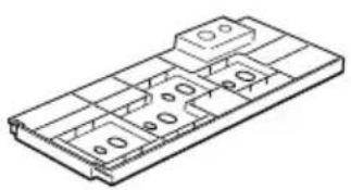 | 2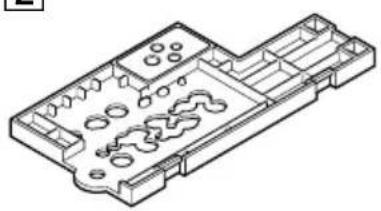 | 3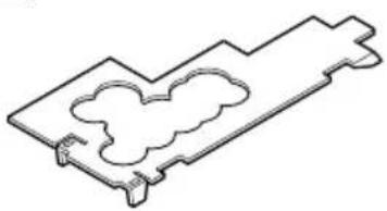 |
4 | 5 | 6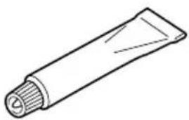 |
7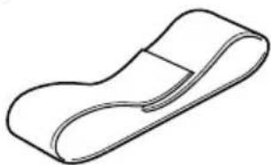 | 8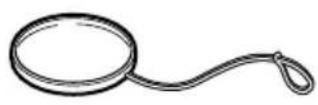 | 9 |
1 Adaptor A (1)
2 Adaptor B (1)
3 Adaptor C (1)
4 Mounting screw plate (1)
5 O-rings (2)
6 Grease (1)
7 Accessory belt (1)
8 Colour filter (1)
9 Viewfinder adaptor (1)
1 Preparing the adaptor
The adaptor and the position of the mounting screw plate depend on the video camera model. See the following page when attaching the adaptor and mounting screw plate.
Check the position for the video camera recorder you use.
| Video camera recorderCCD- | Position of the mounting screw plate on the adaptor | |
| Without a wide-conversion lens | With a wide-conversion lens | |
| TRV30/TRV40/TRV70/TRV30E/TRV40E/TRV60E/TRV70E | A1 | A2 |
| TR330/TR403/TR420/TR440/TR490/TR590/TR330E/TR340E/TR401E/TR402E/TR410E/TR420E/TR440E/TR490E/TR510E/TR520E/TR590E | A3 | |
| TR1/TR3/TR8/TR1E/TR3E/TR8E/TR18E | B1 B3 | |
| TR506/TR507/TR501E/TR502E/TR503E/TR506E/TR620E/TR720E/TR740E/TRV11/TRV12/TRV21/TRV34/TRV44/TRV10E/TRV11E/TRV12E/TRV14E/TRV21E/TRV24E/TRV44E | B2 B5 | |
| TRV94/TRV54E/TRV56E/TRV94E | B2 B9 | |
| TR3000/TR3000E | B3 B6 | |
| TR555/TR555E | B3 B7 | |
| TRV101/TRV101E | B3 | — |
| TR910/TR610E/TR710E/TR760E/TR810E/TR910E | B4 B6 | |
| TR2200/TR2300/TR3300/TR2200E/TR2300E/TR3100E/TR3300E/TR3400E/TRV31/TRV41/TRV51/TRV91/TRV31E/TRV41E/TRV51E/TRV61E/TRV81E/TRV91E | B4 B7 | |
| TRV64E/TRV820E/TRV825E/TRV920E | B5 B8 | |
| TR1100E/TR3200E/TRV300E | B5 B9 | |
| TR311/TR413/TR414/TR940/TR311E/TR411E/TR511E/TR512E/TR640E/TR730E/TR840E/TR845E/TRV15/TRV25/TRV35/TRV65/TRV75/TRV3E/TRV13E/TRV15E/TRV23E/TRV35E/TRV45E/TRV55E/TRV65E/TRV69E/TR412E | B5 B12 | |
| TRV95/TRV89E/TRV95E/TRV99E | B8 B9 | |
A, B — adaptor to be used.
1, 2, 3... — corresponding number on the adaptor.
Notes
- You should use the wide conversion lens VCL-0637H (not supplied) for the CCD-TRV95/TRV89E/TRV95E/TRV99E video camera recorder.
- The CCD-TRV101/TRV101E video camera recorder cannot be fitted with a wide conversion lens.
- When you attach a wide conversion lens to the CCD-TR820E/TR825E/TR1100E/TR2200/TR2200E/TR3100E/TR3200E/TRV10E/TRV11/TRV11E/TRV12/TRV12E/TRV21/TRV21E/TRV31/TRV31E/TRV41/TRV41E/TRV51/TRV51E/TRV61E/TRV81E/TRV91/TRV91E/TRV300E video camera recorders, you cannot attach the viewfinder adaptor.
Preparing
- When you attach a wide conversion lens to the CCD-TRV10E/TRV11/TRV11E/TRV12/TRV12E/TRV21/TRV21E video camera recorders, you cannot attach Sony battery NP-99/4500.
- When you attach a wide conversion lens to the CCD-TR1100E/TR2200/TR2200E/TR2300/TR2300E/TR3100E/TR3200E/TR3300/TR3300E/TR3400E/TRV89E/TRV95/TRV95E/TRV99/TRV99E/TRV300E video camera recorders, you cannot attach Sony battery NP-F930/F950.
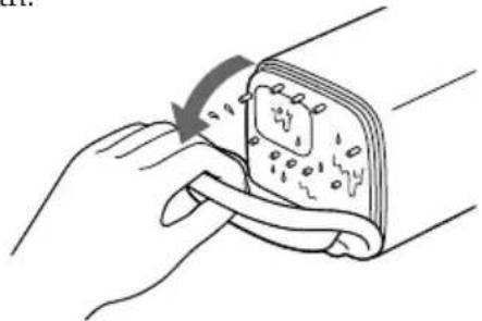
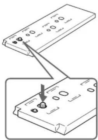
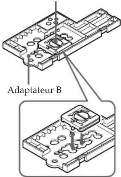
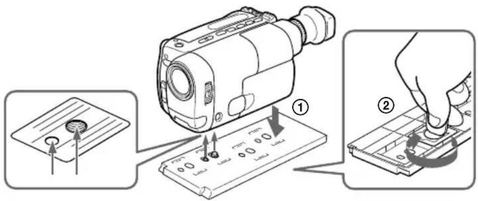
Attaching the mounting screw plate to the adaptor
Adaptor A Adaptor B
Mounting screw plate
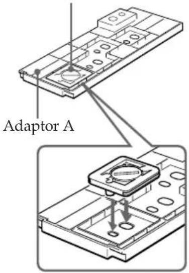
Mounting screw plate
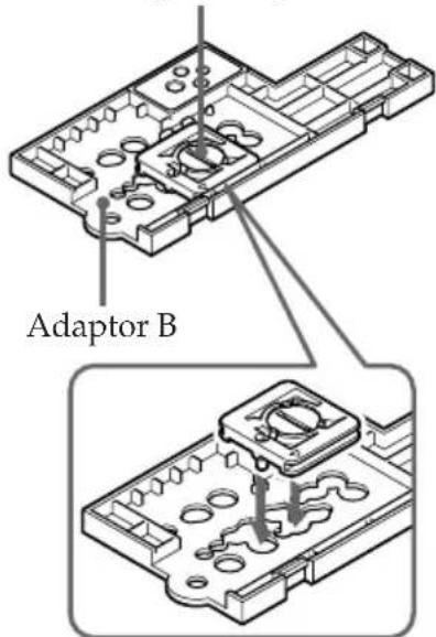
natural_image
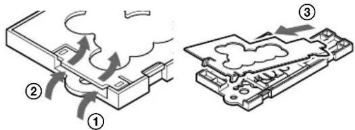
Diagram showing two steps of a mechanical component with holes and a downward arrow indicating motion (no text or symbols)Attach adaptor C to adaptor B.
Adaptor CTo disassemble after using
To detach adaptor C from adaptor B
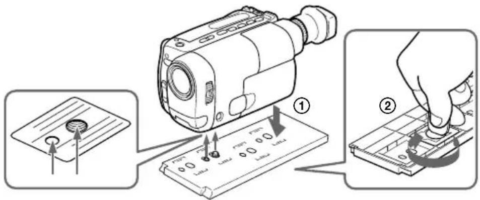
2 Preparing the video camera recorder
(1) Remove the lens cap, shoulder strap, filter, etc., from the video camera recorder.
(2) Attach a charged battery pack and insert a video cassette.
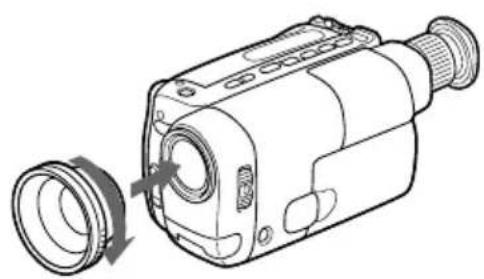
(3) Attach the wide conversion lens (not supplied).
By attaching the wide conversion lens, the shooting coverage becomes wider, and the subject size becomes smaller.
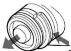
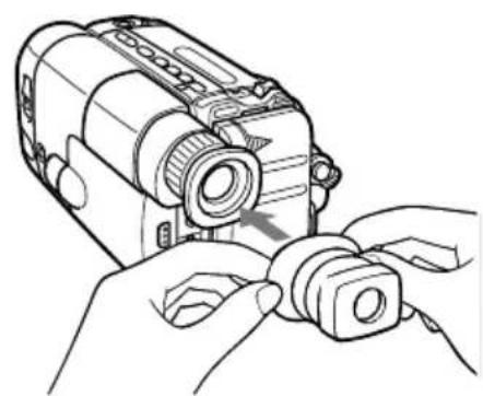
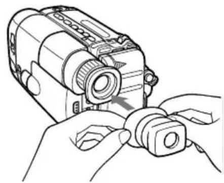
(4) Attach the Viewfinder adaptor.
If the viewfinder adaptor is loose when it is attached, bend the eyecup of the camcorder and attach it again.
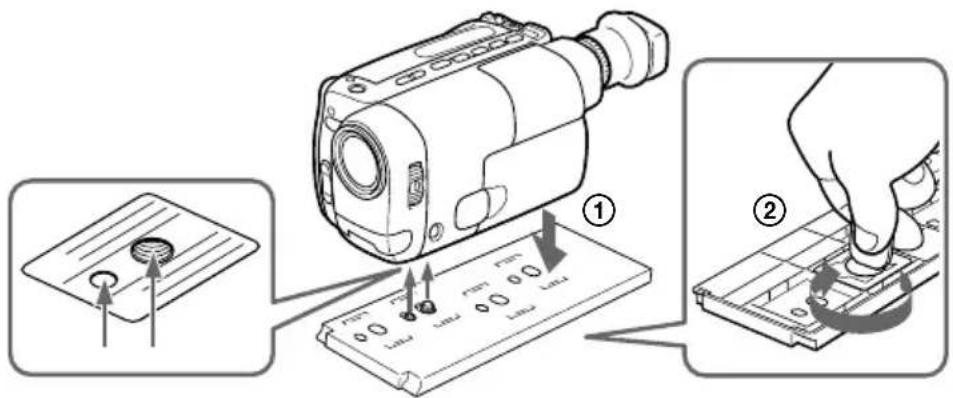
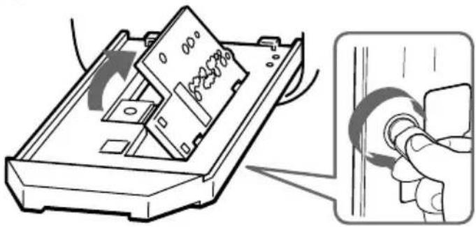
(5) When using adaptor A, attach it to the video camera recorder.
Check that the position of the mounting screw plate is correct (See pages 7). When using adaptor B, skip this step.
3
natural_image
Technical line drawing of a camera module with lens and adjustment knob (no text or symbols)4

natural_image
Line drawing of hands assembling or adjusting a camera module (no text or symbols visible)5

Preparing
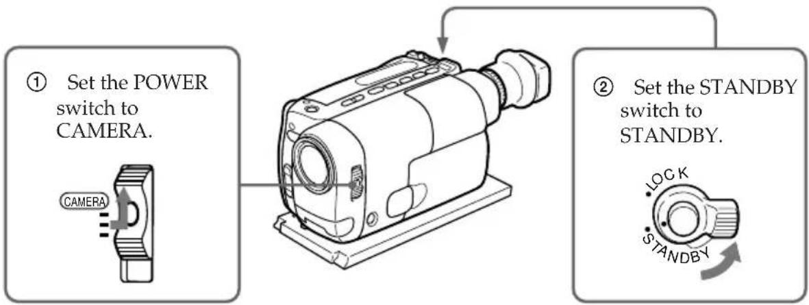
(6) Adjust the video camera recorder.
Refer to the operation manual of your video camera recorder.
flowchart
graph TD
    A["① Set the POWER switch to CAMERA."] --> B["Image of camera"]
    C["② Set the STANDBY switch to STANDBY."] --> D["Lock & Standby"]
The following adjustments are needed when your video camera recorder has the corresponding function.
Refer to the operation manual of the video camera recorder for details.
| White balance Normally set to ⚙ (outdoor). Set to ⚙- (indoor) for night diving. |
| Shutter speed Set where no indicator appears. |
| Program AE Set where no indicator appears. |
| Brightness Turn off the indicator. |
Notes
- On some video camera recorder models, you cannot adjust the focus with the button on the marine pack.
Set the focus to auto focus mode (see page 3).
- When the viewfinder adaptor is attached to the viewfinder of your video camera recorder, you get a wide view of what appears in the viewfinder screen.
However, the view may be distorted depending on the viewing angle.
3 Attaching the video camera recorder to the marine pack
(1) Attach the video camera recorder to the marine pack.
Check the position of the adaptor (See page 7).
When using adaptor A
① Connect the microphone cable to MIC. (The sound is recorded in monaural.)
③ Connect the remote control cable to ⬆ REMOTE.
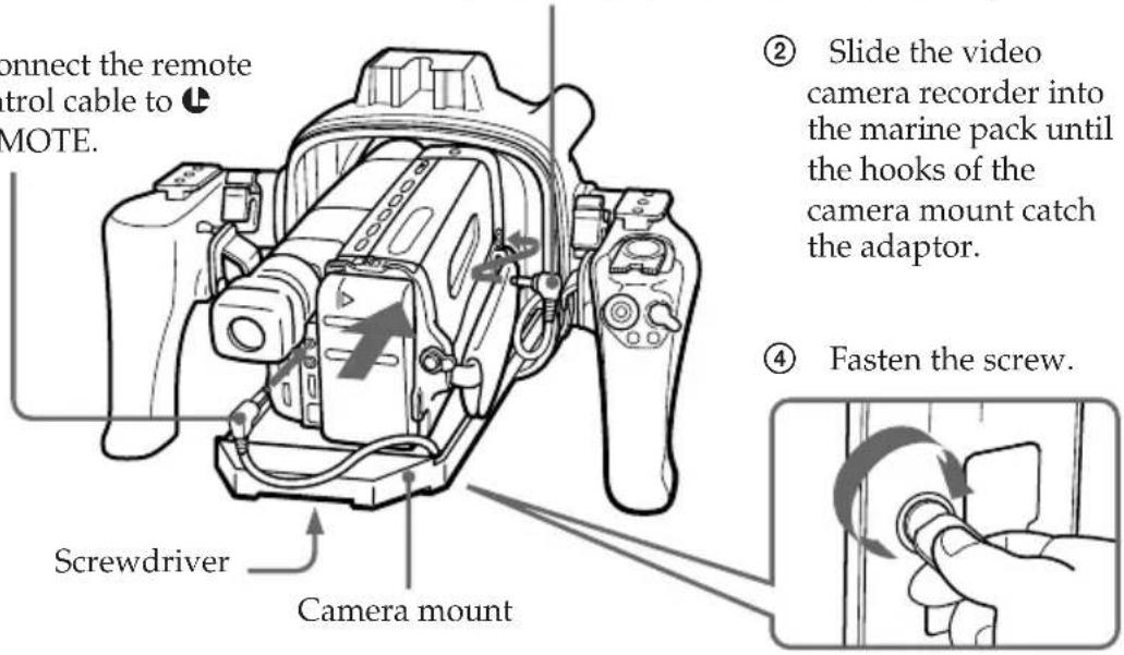
② Slide the video camera recorder into the marine pack until the hooks of the camera mount catch the adaptor.
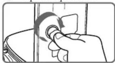
④ Fasten the screw.
natural_image
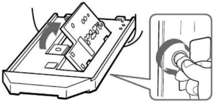
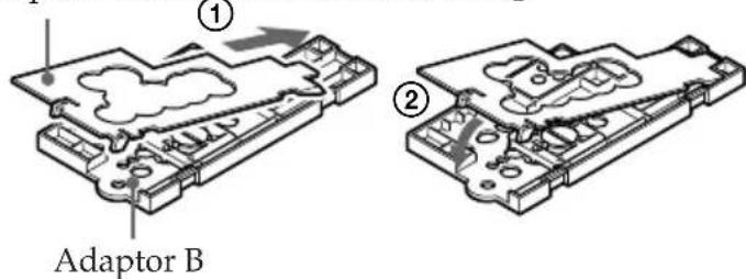
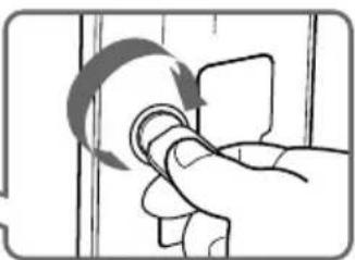
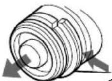
Illustration of a hand holding a doorbell with a curved arrow indicating rotation (no text or symbols)When using adaptor B
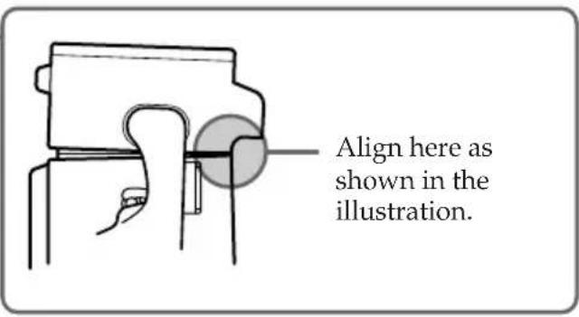
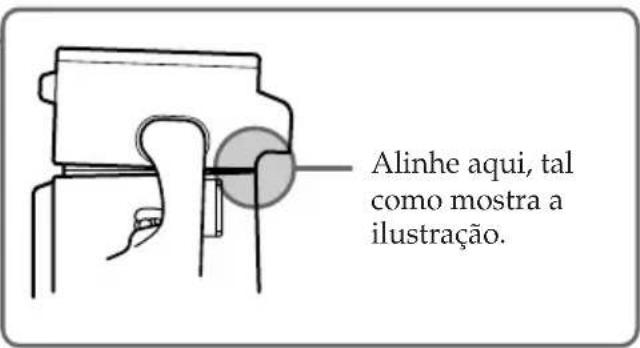
① Align the right side of the adaptor with the hooks of the camera mount, then push down the adaptor.
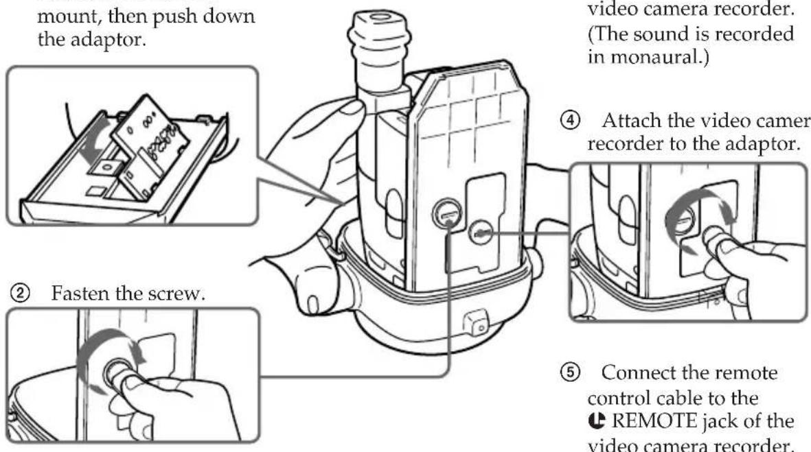
③ Connect the microphone cable to MIC jack of the video camera recorder. (The sound is recorded in monaural.)
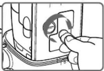
④ Attach the video camera recorder to the adaptor.
natural_image
Hand inserting a circular component into a device (no text or symbols visible)⑤ Connect the remote control cable to the ⬆ REMOTE jack of the video camera recorder.
Preparing
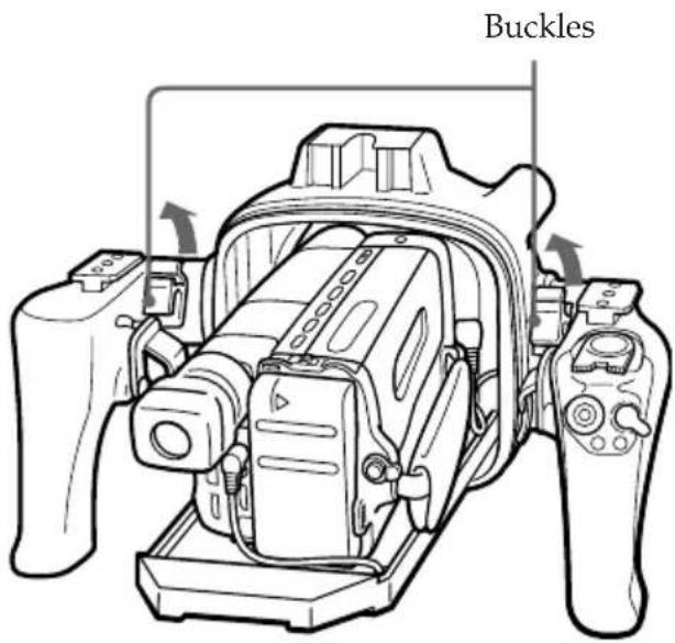
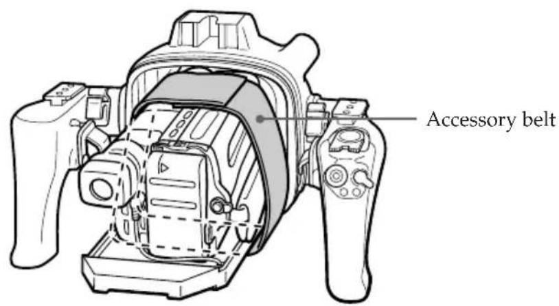
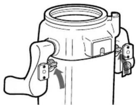
(2) Raise the buckles until they stop.
(3) Fasten the video camera recorder with the accessory belt.
When you fasten the video camera recorder with accessory belt, take care not to touch the zoom button.
2
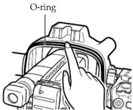
Check the O-ring and grease it slightly.
3
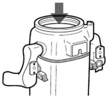
(4) Attach the front shell to the rear shell.
natural_image
Technical line drawing of a mechanical component with a downward arrow indicating force or direction (no text or symbols present)① Put the front shell on the rear shell.
natural_image
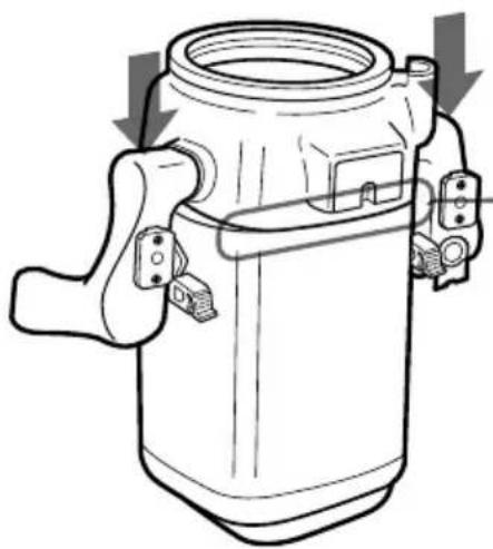
Technical line drawing of a mechanical device with no visible text or symbols② Press the top of both grips frimy.
natural_image
Technical line drawing of a mechanical component with no visible text or symbols③ Lower both buckles at the same time until they are locked. You will hear a click.
Now you ready for underwater recording.
Set the STANDBY/LOCK switch of the marine pack to LOCK.
If you set it to STANDBY, the battery may be used up before recording.
Recording
Check that the equipment operates correctly and that there is no water leak at a depth of about one meter (3 feet) before you dive deeper.
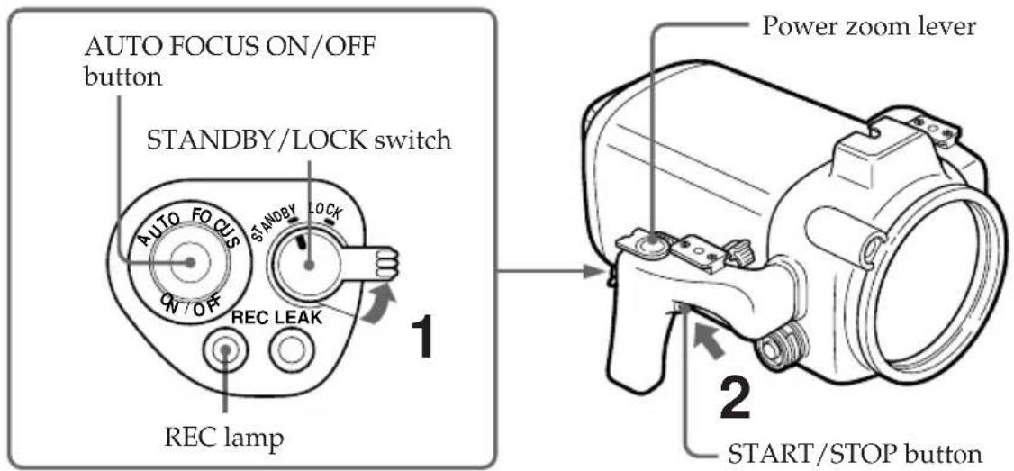
(1) Set the STANDBY/LOCK switch to STANDBY.
(2) Press START/STOP button to start recording.
The REC lamp (red) lights up during recording.
To stop recording
Press the START/STOP button.
To zoom
Slide the power zoom lever towards T for telephoto (subject appears closer) or W for wide-angle (subject appears farther away). The zooming speed can be changed on some video camera recorder models from a slow speed to faster by sliding the zooming lever a little more.
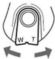
Wide-angle
Telephoto
When you set the power zoom lever to the full wide-angle position (macro), specks or bubbles on the front glass may come into focus. In this case, slide the power zoom lever a little towards T and return towards W.
To keep a subject in focus
After you focus on a subject, press AUTO FOCUS ON/OFF button to set the video camera recorder to manual focus mode.
Even if fish swim between the video camera recorder and the subject, you can still keep the subject in focus.
Note
On some video camera recorder models, the AUTO FOCUS ON/OFF button is not operative.
Set the video camera recorder to auto focus mode (see page 3).
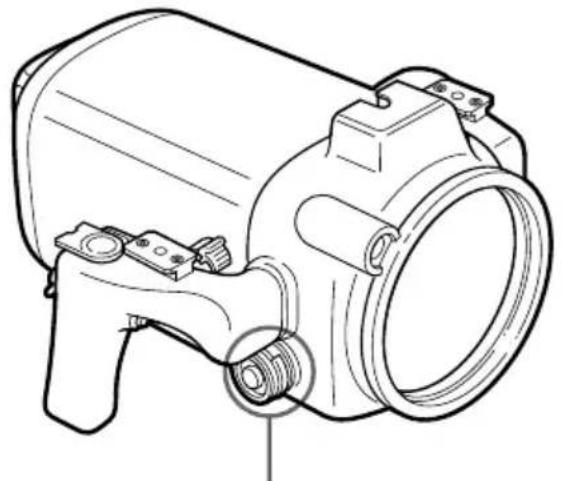
To attach/detach the lid of the video cable connector
A video cable connector is provided so that video equipment can be connected to the marine pack in the future.
When you reattach the lid, grease the O-ring of the lid before inserting it into the connector.
natural_image
Technical line drawing of a mechanical device with no visible text or symbolsTo detach To attach
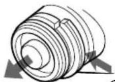
② pull out.
① While pressing here,
② press in.
① While pressing here,
Note
Do not remove the lid underwater.
When the LEAK lamp flashes
If water happen to leak in, the LEAK lamp (yellow) flashes.
In such a case, remove the marine pack from the water as soon as possible, keeping it horizontal. Be sure to surface following the safety rules for diving.
Dry the marine pack with a soft cloth and then open it.
To switch off the lamp, disconnect the remote control cable.
Check the cause of the leak.
If the video camera recorder is wet, take it to the nearest Sony dealer immediately.
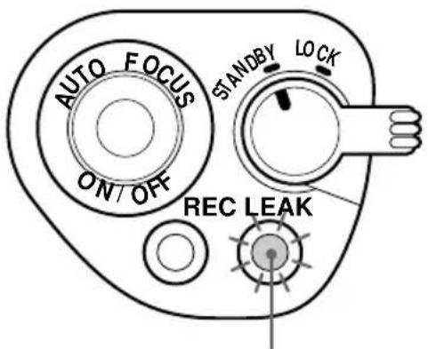
LEAK lamp (yellow)
Removing the camcorder
Before opening the marine pack, rinse it with fresh water and dry with a soft cloth.
Note
When you open the marine pack, follow this procedure to prevent the video camera recorder from getting wet.
• Dry the marine pack well.
- Wipe off any water between the front and rear shells with a towel.
• Make sure you are dry. Take care that no water drips from your diving suit.
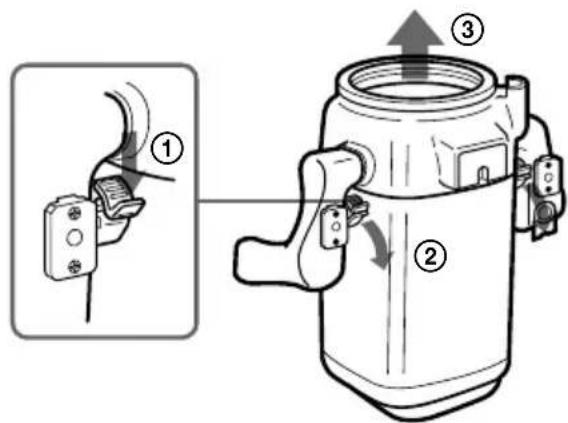
(1) Remove the accessories.
(2) Open the marine pack.
Unfasten both buckles and remove the front shell.
(3) Take the video camera recorder out of the front shell.
2
3
① Disconnect the remote control cable.
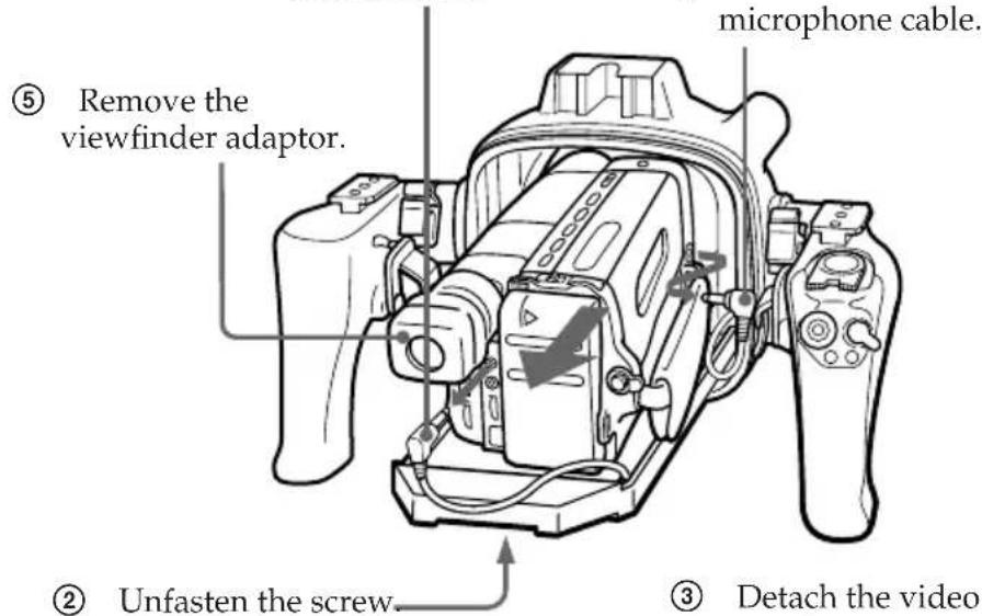
④ Disconnect the microphone cable.
(4) Insert the remote control plug and the microphone plug where they were.
(5) Remove the adaptor.
4
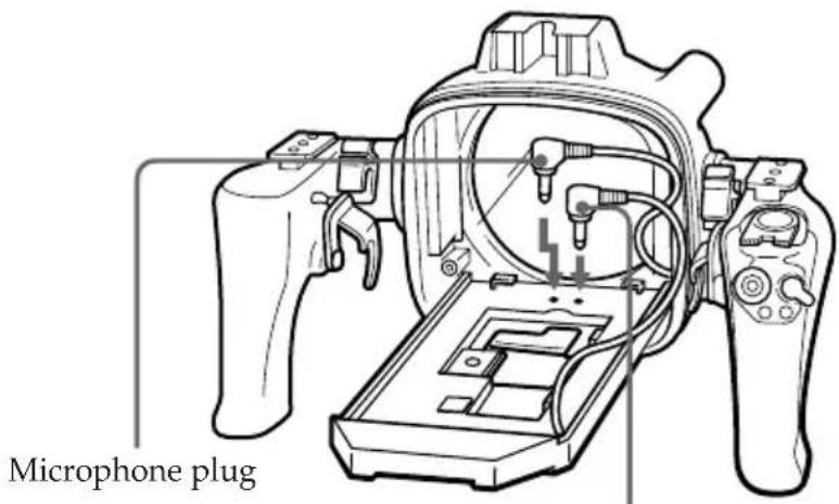
Remote control plug
5
Adaptor A
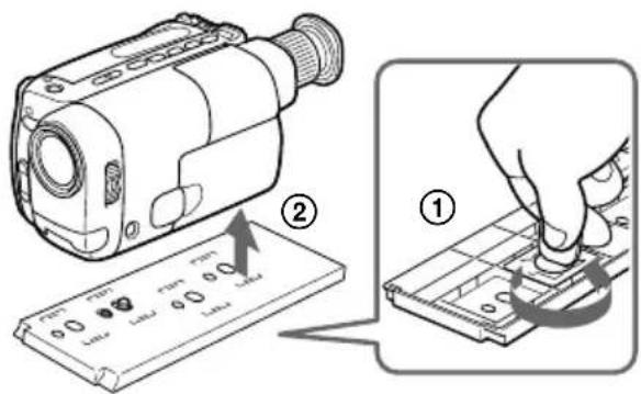
Adaptor B

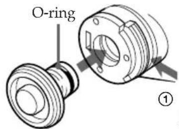
natural_image
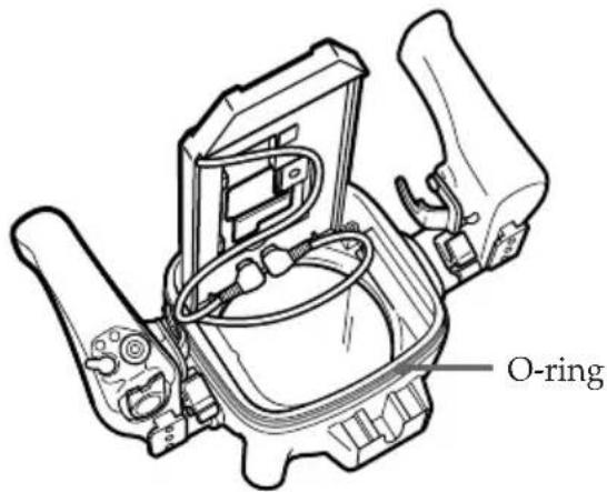
Diagram showing a device being processed with a magnified view of the internal components (no text or symbols present)Note on the O-ring
The O-ring assures the waterproof function of the marine pack. To maintain waterproof integrity, use it correctly. Incorrect handling may cause water to leak in.
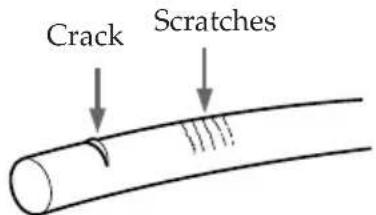
Check that there are no scratches or cracks
Scratches or cracks on the O-ring may cause water to leak in. If the O-ring is damaged in this way, replace it with a new one. Do not remove the O-ring from the groove with a metal tool or a tool with a sharp point.
Remove any dust, sand or hair from the O-ring
Make sure there is no dust, sand or hair on the O-ring, in the groove, or on the surface of the marine pack where the O-ring touches. If there is, clean them completely, or the O-ring and the surface of the marine pack may be damaged and water may leak in.
Grease the O-ring
The grease protects the O-ring from wear.
Check that there are no cracks or dust on the O-ring, then grease it using your finger. While greasing, double check that there are no cracks or dust.
Never use cloth or paper to apply grease because the fibers may cling.
Do not use any type of grease other than the supplied one, or it may damage the O-ring. If you run out of silicone grease (2-115-921-01) you can purchase it from your nearest Sony Service Center.
Do not twist the O-ring
Put the O-ring in the groove evenly. Never twist it.
Do not pinch the O-ring with the marine pack
When jointing the front and rear shells, take care not to pinch the O-ring between them. If this happens, not only will the O-ring be damaged, but water may leak in.
Storage
Put the supplied spare O-rings in the original carton and store it in a cool place.
- Do not expose the O-ring to direct sunlight.
- Do not place a heavy object on the O-ring.
- Do not fold the O-ring.
Useful life of the O-ring
Depending upon the maintenance and the length of use, we recommend changing the O-ring every one or two years.
The O-ring (3-952-928-01) can be replaced at your nearest Sony Service Center.
Underwater recording
Recording underwater is different from recording on land because it is affected by the clarity and depth of the water and the light conditions. The following are hints for good recording underwater.
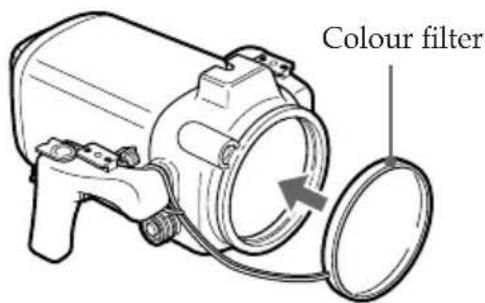
Colour characteristic underwater
Water absorbs light, especially red light, so that objects in deep water or in the distance are seen as bluish. The colour of objects is affected by the clarity of the water.
To record the subject with nearly actual colour, use the colour filter.
Best time for recording
The best recording time is about from 10:00 a.m. to 2:00 p.m. When the sun is its highest, optimum results can be obtained.
Subject size underwater
Since the refractive index underwater is higher than that in air, an object appears 1/4 more closer, and therefore larger. This phenomenon affects the lens on the video camera recorder as well as the human eye. Using a wide-conversion lens (not supplied) is recommended.
Camera work on slow and stable motion
When recording, keep your body stable.
An unstable shot will be magnified on the TV screen. Move the video camera recorder as slowly as possible. As most of the object underwater move, you can record a good programme without moving the video camera recorder.
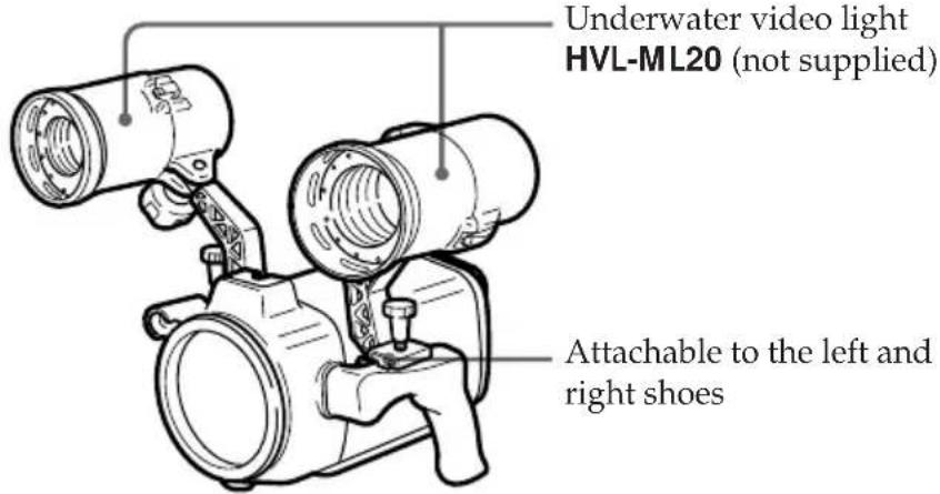
Underwater video light
In deep water or under rocks where direct sunlight does not reach, recording with an underwater video light is recommended.
To record at night, use a powerful underwater video light.
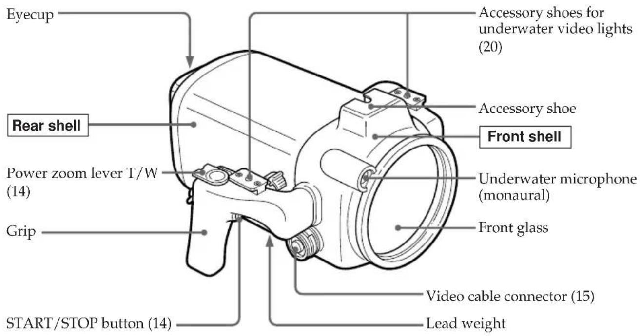
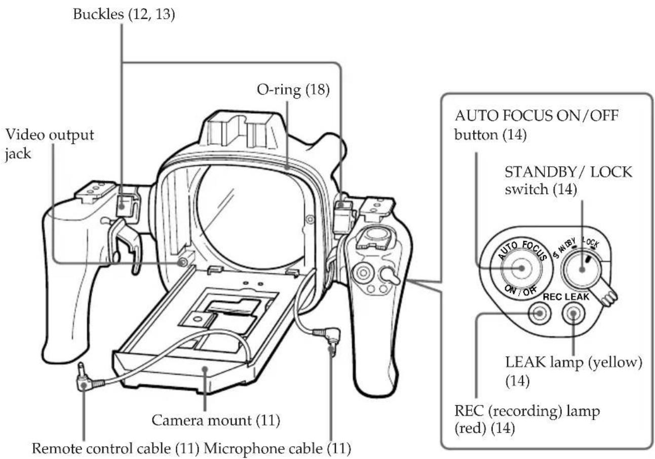
Labeling parts and controls
- For the use of each part or control, see the pages indicated in parenthesis.
Specifications
Compatible video camera recorder
See page 3.
Material
Aluminum alloy, glass, plastic, lead
Waterproofing
O-ring, 2 buckles
Usable depth
Up to 75 meters (246 feet)
Underwater microphone
Condenser microphone (monaural)
Controllable function
Power on/off, recording start/stop, auto focus on/off, power zooming
Dimensions
Approx. 337 · 201 · 327 mm (w/h/d)
(13^3/8 · 8 · 12^7/8 in.)
Mass
Approx. 8 kg (17 lb 10 oz)
Supplied accessories
Adaptor A (1)/B (1)/C (1)
Mounting screw plate (1)
O-rings (2)
Grease (1)
Accessory belt (1)
Colour filter (1)
Viewfinder adaptor (1)
Recommended accessories
Underwater video light HVL-ML20
Carrying case LCH-M40
Design and specifications are subject to change without notice.
Tables des matières
natural_image
Illustration of a hand pressing down on a device with a curved arrow indicating motion (no text or symbols)natural_image
Diagram showing two views of a device with holes and a downward arrow indicating a process (no text or symbols present)Adaptateur B
Plaque de montage
natural_image
Technical line drawing of a camera module with lens and adjustment knob (no text or symbols)4

natural_image
Line drawing of hands operating a camera with a cable (no text or symbols)5
Préparation
natural_image
Hand operating a mechanical device with a circular component, no visible text or symbolsnatural_image
Technical line drawing of a mechanical component with a downward arrow indicating force or direction (no text or symbols present)natural_image
Technical line drawing of a mechanical device with no visible text or symbolsnatural_image
Simple line drawing of a mechanical device with a circular component inserted (no text or symbols)natural_image
Technical line drawing of a mechanical component with no visible text or symbolsnatural_image
Technical line drawing of a mechanical device with no visible text or symbolsRetrait Insertion
natural_image
Technical line drawing of a threaded mechanical component with directional arrows indicating motion (no text or symbols)3
Adaptateur B

natural_image
Diagram showing a device being processed with a magnified view of the internal components (no text or symbols present)natural_image
Illustration of a hand pressing down on a wristband with a curved arrow indicating motion (no text or symbols)natural_image
Diagram showing two steps of a device with circular components and an arrow indicating a process (no text or symbols present)natural_image
Technical line drawing of a camera module with lens and adjustment knob (no text or symbols)4
natural_image
Line drawing of hands operating a camera with a cable (no text or symbols)5
Preparativos
natural_image
Illustration of a hand pressing down on a door with a curved arrow indicating rotation (no text or symbols)natural_image
Hand inserting a component into a device (no text or symbols visible)natural_image
Technical line drawing of a mechanical component with a downward arrow indicating force or direction (no text or symbols present)natural_image
Technical line drawing of a mechanical device with directional arrows indicating movement or force (no text or symbols present)natural_image
Technical line drawing of a mechanical component with no visible text or symbolsnatural_image
Technical line drawing of a mechanical device with no visible text or symbolsPara quitar Para colocar
3
① Desconecte el cable de control remoto.
Adaptador B
natural_image
Diagram showing a device with internal components and a close-up of a hand using a tool (no text or symbols present)natural_image
Diagram showing two steps of a mechanical component with holes and a downward arrow indicating motion (no text or symbols)natural_image
Technical line drawing of a camera module with lens and adjustment knob (no text or symbols)4
natural_image
Line drawing of hands operating a camera module with a clip (no text or symbols)5
natural_image
Illustration of a hand pressing down on a door with a curved arrow indicating rotation (no text or symbols)natural_image
Diagram of a device being placed on a base, showing a component with no visible text or symbols.② Aperte o parafuso.
natural_image
Hand holding a mechanical component with a circular arrow indicating rotation (no text or symbols)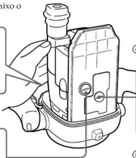
natural_image
Technical line drawing of a mechanical device with no visible text or symbolsnatural_image
Line drawing of a hand operating a mechanical component with a circular valve (no text or symbols)natural_image
Technical line drawing of a mechanical component with a downward arrow indicating force or direction (no text or symbols present)natural_image
Technical line drawing of a mechanical device with no visible text or symbols② Pressione o topo de ambas as pegas firmemente.
natural_image
Technical line drawing of a mechanical component with no visible text or symbolsnatural_image
Technical line drawing of a mechanical device with no visible text or symbolsPara desacoplar Para acoplar
② puxe para fora.
3
Adaptador B