
P 5500 M - Pump METABO - Free user manual and instructions
Find the device manual for free P 5500 M METABO in PDF.
| Product type | Surface pump |
| Brand | Metabo |
| Model | P 5500 M |
| Dimensions (L × W × H) | 480 × 245 × 300 mm |
| Weight (empty) | 12.3 kg |
| Supply voltage | 230 V ~, 50 Hz |
| Rated power | 1500 W |
| Maximum flow rate | 5500 l/h |
| Maximum discharge head | 55 m |
| Maximum discharge pressure | 5.5 bar |
| Maximum suction head | 9 m |
| Maximum water temperature | 50 °C |
| Protection rating | IP44 |
| Protection class | I |
| Suction connection | 1" (internal thread) |
| Discharge connection | 1" (internal thread) |
| Intended use | Transport of clean water (watering, irrigation, swimming pools, etc.) |
| Routine maintenance | Drain after use, clean filter, protect from frost |
| Safety instructions | Do not use for drinking water; do not run dry; use a 30 mA residual current circuit breaker |
| Spare parts and accessories | Connection kit, Hydromat, pressure cutoff, filters, etc. |
Frequently Asked Questions - P 5500 M METABO
User questions about P 5500 M METABO
0 question about this device. Answer the ones you know or ask your own.
Ask a new question about this device
Download the instructions for your Pump in PDF format for free! Find your manual P 5500 M - METABO and take your electronic device back in hand. On this page are published all the documents necessary for the use of your device. P 5500 M by METABO.
USER MANUAL P 5500 M METABO
natural_image
Line drawing of a portable electric vacuum cleaner with attached cable (no text or symbols)
(D) Originalbetriebsanleitung. 3
ENG Original operating instructions 8
F Instructions d'utilisation originales ..... 13
NL Origineel gebruik aanwijzing....19
ES Manual de instrucciones original ..... 24
DA Original brugsvejledning 30
SV Original bruksanvisning 35
SLO Izvirna navodila za uporabo. 40
FIN Alkuperäiskäyttöohje 45
DE EN
EG-KONFORMITÄTSERKLÄRUNGVEC-DECLARATION OF CONFORMITY
We herewith declare in our sole responsibility that this product complies with the following standards* in accordance with the regulations of the undermentioned Directives** issuing test office *** measured/guaranteed noise sound power level****
NL
Director Innovation, Research and Development
Dokumentationsbevollmächtigter/ responsible person for documentation/ Chargé de la documentation
Metabowerke GmbH
Metabo-Allee 1
D - 72622 Nürtingen
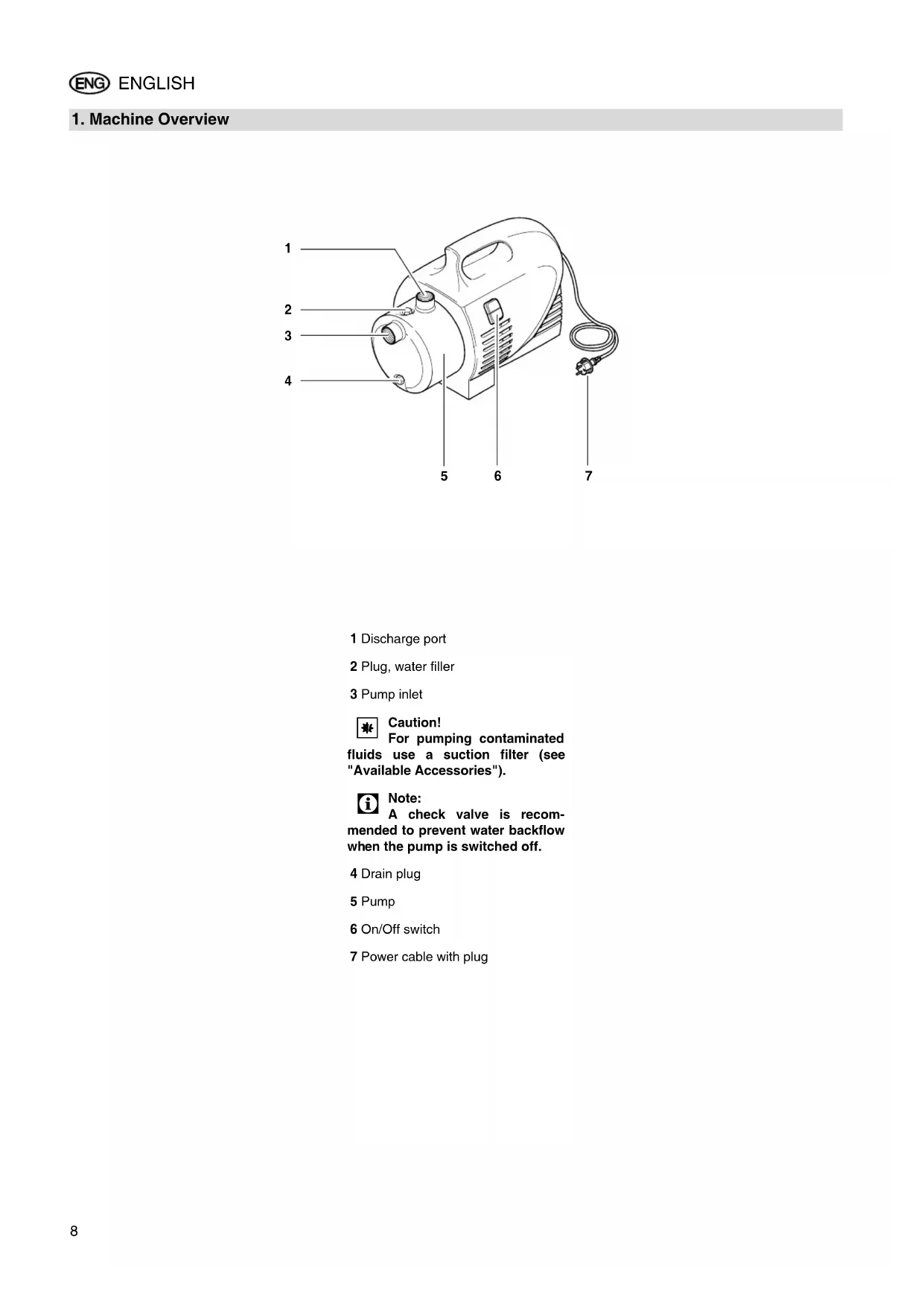
For pumping contaminated fluids use a suction filter (see "Available Accessories").

Note:
A check valve is recommended to prevent water backflow when the pump is switched off.
4 Drain plug
5 Pump
6 On/Off switch
7 Power cable with plug
Table of Contents
-
Machine Overview ......8
-
Please Read First!...... 9
-
Range of Application and Pumping Media ....9
-
Safety......9
4.1 Specified conditions of use .....9
4.2 General safety instructions .....9
- Prior to Operation......9
5.1 Installation....10
5.2 Suction line connection.....10
5.3 Discharge hose connection .....10
5.4 Mains connection....10
5.5 Filling the pump and priming.....10
- Operation....10
6.1 Commissioning ....10
6.2 Pump characteristic curve .....10
- Care and Maintenance......11
7.1 Periodic maintenance .....11
7.2 Danger of freezing .....11
7.3 Equipment dismounting and storing ....11
- Trouble Shooting .....11
8.1 Fault finding .....11
-
Repairs......11
-
Environmental Protection......11
-
Available Accessories......11/50
-
Technical Specifications......12
2. Please Read First!
- Read these instructions before use. Pay special attention to the safety instructions.
- Disregard of the operating instructions invalidates the manufacturer's warranty; the manufacturer is not liable for any damages resulting from such disregard.
- If you notice transport damage while unpacking, notify your supplier immediately. Do not operate the machine!
- Dispose of the packing in an environmentally friendly manner. Take to a proper collecting point.
- Keep these instructions for reference on any issues you may be uncertain about.
- If you lend or sell this machine be sure to have the instructions go with it.
3. Range of Application and Pumping Media
This equipment is intended for pumping clear water in domestic applications, such as
- irrigation,
- well, rain and service water pumping,
- draining of pools, garden ponds and water tanks.
The max. permissible temperature of the pumped medium is 35 °C.
4. Safety
4.1 Specified conditions of use
This equipment must not be used to supply drinking water or for pumping foodstuff.
Explosive, flammable or aggressive fluids and substances detrimental to health must not be pumped.
This equipment is not suitable for commercial or industrial use.
Alteration of the equipment or use of parts not approved by the equipment manufacturer is not permitted.
Any inexpert use the equipment is not as specified; it can cause unforeseen damage!
4.2 General safety instructions
Children, juveniles and persons not familiar with the instructions are not permitted to operate the pump.
When used in swimming pools and garden ponds and their range of protection, the regulations according to DIN VDE 0100-702, -738 are to be observed.
When used as domestic water supply any applicable local regulations pertaining to water supply and waste water disposal, plus DIN 1988 (where applicable) are to be observed.
The following residual risks do principally exist when operating pumps – they can not be fully eliminated even by employing safety devices.

Hazard by ambient conditions!
Do not expose to rain. Do not operate in damp or wet environment.
Do not direct water jet directly against the equipment or other electrical parts! Risk of fatal electric shock!
Do not use the pump in hazardous locations or near inflammable liquids and gases!

Danger: Hot water!
If the shut-off pressure of the pressure switch cannot be reached due to poor pressure conditions or a defective pressure switch the water can heat up within the pump as a result of internal circulation.
Through this the pump and the connection lines can become damaged or
leaky, allowing hot water to escape. Danger of scalding!
- Do not operate the pump against a closed pressure line for longer than 5 minutes.
- Unplug the pump and allow to cool. A specialist must check the system to make sure it is in perfect working order before it can be used again.

Danger! Risk of electric shock!
Always unplug before servicing.
Do not touch the plug with wet hands! To unplug always pull on the plug, not the power cable.
Do not buckle, squeeze, drag or drive over power cable and extension cables; protect from sharp edges.

Danger by pump failings!
Before each use check the equipment, especially the power cable, plug and electrical parts for possible damage. Risk of fatal electric shock!
A damaged pump must be workmanlike repaired before it can be used again.
Do not attempt to repair the equipment yourself! Only trained specialists are permitted to service or repair pumps.

Caution!
To avoid water damage, e.g.
flooded rooms, caused by pump malfunctions or defects:
• provide for suitable safety measures such as the following:
- alarm or
– collection tank with monitoring.
The manufacturer is not liable for any damage caused by:
– improper use of the pump;
– overloading of the pump through continuous operation;
– failure to operate and store the pump in a frost-free environment;
- unauthorised modification of the pump (repairs to electrical equipment may only be carried out by qualified electricians!);
- use of spare parts which have not been tested and approved by the manufacturer; or
– use of unsuitable installation materials (fittings, connection lines etc.).
Suitable installation materials:
– pressure-resistant(min. 10 bar)
- heat-resistant (min. 100°C).
5. Prior to Operation
The equipment is easily assembled and connected.
If in doubt, contact your specialist supplier or qualified electrician.
5.1 Installation
- The equipment must be placed on a plane and level surface, suitable of bearing the weight of the equipment fully filled with water.
- To prevent vibrations, the equipment should not be fastened with screws but placed onto an elastic base.
- The installation location should be well vented and protected from atmospheric exposure.
- When operated at garden ponds and pools the equipment must be set up safe against flooding and protected from falling into the water. Any additional legal requirements are to be observed.
5.2 Suction line connection

Note:
① Possibly further accessories may be required for connection (see "Available Accessories").

Caution!
The suction line needs to be installed in such manner that it does not exert mechanical force or distortion to the pump.

Caution!
When pumping contaminated fluids install a suction strainer to protect the pump from sand and dirt.

Note:
A check valve is recommended to prevent water backflow when the pump is switched off.
- All screw fittings need to be sealed with thread sealing tape; leakage places cause the priming of air and reduce or prevent the priming of water.
- The suction line should have at least 1" (25 mm) inner diameter; it must be non-buckling and vacuum-proof.
- Keep suction line as short as practical, since with increasing length the pump capacity is reduced.
- The suction line should raise towards the pump to prevent air locks.
- A sufficient water supply must be ensured, the foot valve at the end of the suction line must be submerged in water at all times.
5.3 Discharge hose connection

Note:
Possibly further accessories may be required for connection (see "Available Accessories").

Caution!
The discharge (or pressure) line needs to be installed in such manner that it does not exert mechanical force or distortion to the pump.
- All screw fittings should be sealed with thread sealing tape to prevent leakage.
- All parts of the pressure line must be resistant to internal pressure.
- All parts of the pressure line must be installed in a workmanlike manner.

Danger!
Improper installation and use of parts not resistant to internal pressure can cause the pressure line to break during operation. Risk of personal injury by liquid spurting from the line under high pressure!
5.4 Mains connection

Danger! Risk of electric shock! Do not operate the equipment in wet environment and only under the following conditions:
- Connect only to an earthed outlet that is properly installed, earthed and tested.
- Mains voltage and fuse protection must correspond to those stated in the "Technical Specifications".
- When operated at pools, garden ponds and similar locations, the equipment must be protected by a residual current operated device (RCD, 30 mA) (DIN VDE 0100 -702, -738 or equivalent applicable local regulations). We recommend the use of RCD's as a general precaution for personal protection.
- When operated outdoors the electrical connections must be splash-proof; they must not be placed in water.
- Use only extension cables of sufficient lead cross section (see "Technical Specifications"). Unroll cable reels fully.
5.5 Filling the pump and priming

Caution!
After installation, loss of water or priming of air the pump needs to be filled with water. Starting the pump without water causes damage!

Note:
The suction line does not need to be filled, the pump is self-priming. However, depending on length and diameter
of the suction line it may take some time until pressure has built up.
- Remove the water filler plug, complete with gasket.
- Slowly pour in clear water, until the pump is filled.
- To reduce the time needed for priming you can also fill the suction line.
- Replace the water filler plug, complete with gasket.
- Open pressure line (open tap or spray nozzle) for any air to escape during priming.
- Start equipment (see "Operation").
- Switch equipment OFF when water runs out steadily.
6. Operation
Pump and suction line must be connected and filled (see "Prior to Operation").

Caution!
Pump must not run dry. Ensure there is always sufficient pumping medium (water) available.
- If the motor does not start, no pressure is built up or similar effects are evident, switch the equipment OFF – and try to remove the fault (see "Trouble Shooting").
- If the pump should be blocked by a foreign object or the motor overheat, the motor protection will switch the motor off.
6.1 Commissioning

Note:
This pumps runs as long as the ON/OFF switch is switched ON.
- Plug power cable in.
- Switch pump on with the ON/OFF switch.
- Open pressure line (open tap or spray nozzle).
- Check to see that the water comes out!

Caution!
With a closed pressure line do not let pump run for more then 10 minutes, otherwise there could be damage by the water overheating in the pump.
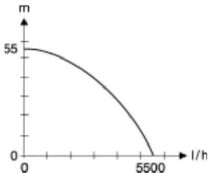
6.2 Pump characteristic curve
The pump characteristic curve shows which pump capacity is possible in dependence on the delivery head.
line
| l/h | m | |-----|----| | 0 | 55 | | 5500| 0 |Pump characteristic curve at 0.5 m suction head and 1" suction hose – for model:
P 5500 M
7. Care and Maintenance

Danger!
Prior to all servicing:
- Switch Off.
- Urplug.
- Ensure that pressure is relieved from equipment and connected accessories.
Repair and maintenance work other than described here must only be carried out by qualified specialists.
7.1 Periodic maintenance
- Check equipment and accessories, especially electrical parts and parts under pressure for possible damage; have repaired, if necessary.
- Check suction and pressure lines for leakages.
- If the pump capacity lessens clean suction strainer and filter cartridge (if installed), replace if necessary.
7.2 Danger of freezing

Caution!
Frost damages the pump and accessories, as both always contain water!
- When there is danger of freezing, dismount equipment and accessories and store at a freeze-proof location (see below).
7.3 Equipment dismounting and storing
- Switch equipment OFF and unplug.
- Open pressure line (open tap or spray nozzle) and drain water completely.
- Drain pump completely; to do so remove the drain plug from the pump
- Disconnect suction and pressure lines from the equipment.
- Store equipment in a frost-free space (at least 5^ C).
8. Trouble Shooting

Danger!
Prior to all servicing:
- Switch Off.
- Unplug.
- Ensure that pressure is relieved from equipment and connected accessories.
8.1 Fault finding
Pump does not run:
- No mains voltage.
- Check cables, plug, outlet and mains fuse.
- Mains voltage too low.
- Use only extension cables with sufficient lead cross section (see "Technical Specifications").
-
Motor overheated, motor protection relay tripped.
-
After cooling of the pump will switch ON again.
- Ensure sufficient ventilation, keep vent slots clear.
- Observe max. temperature of the pumped medium.
- Motor hums but does not start. - With the motor switched OFF, put screwdriver or similar through the fan cover's vent slots and turn the fan.
- Pump blocked or out of order.
- Disassemble pump and clean.
- Clean diffusor, replace if necessary.
- Clean impeller, replace if necessary.
Pump does not prime correctly or runs very noisily:
- Lack of water.
- Ensure there is a sufficient water supply.
- Suction line leaky.
- Seal suction line, tighten screw fittings.
- Suction head too high.
- Observe max.suction head.
- Installcheck valve, fill suction line with water.
- Suction strainer (accessory) blocked.
- Clean, replace if necessary.
- Check valve (accessory) blocked.
- Clean, replace if necessary.
- Water leaks between motor and pump, Ducone seal worn.
- Replace Ducone seal.
- Pump blocked or out of order.
- see above.
Pressure too low:
- Suction line leaky or too much suction head.
- see above.
- Pump blocked or out of order.
- see above.
9. Repairs
Danger!
Repairs to electric tools must only be carried out by a qualified electrician!
Electric tools in need of repair can be sent to an authorised service center in your country. See spare parts list for address.
Please attach a description of the fault to the electric tool.
For shipping:
- Drain pump completely (see "Equipment dismounting and storing").
- Ship equipment in original packing, if possible.
10. Environmental Protection
The packaging of the pump can be 100 % recycled.
Worn out power tools and accessories contain considerable amounts of valuable raw and plastic materials, which can be recycled.
These instructions are printed on chlorine-free bleached paper.
11. Available Accessories
For this equipment the following accessories are available at specialist dealers.
Note: Illustra
Illustrations and stock numbers can be found at the end of these instructions.
A Pump Installation Package, complete with double nipple, check valve, filter short, washable filter cartridge, spiral hose assembly 1 m, thread sealing tape.
B Hydromat HM 1,
for automatic starting when water is drawn and stopping when no water is drawn, keeps the pump from running dry.
C Hydrostop,
for automatic stopping when there
is a lack of water, prevents the
pump from running dry.
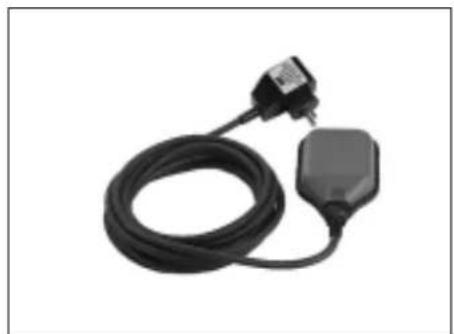
D D ry-running Stop Switch, with 10 m cable, keeps the pump from running dry when pumping from tank, pool, etc.
E Spiral Hose 1"
1) 1 m assembly, with quick release screw fitting at both ends;
2) 4 m, complete with quick release screw fitting and strainer with foot valve;
3) 7 m, complete with quick release screw fitting and strainer with foot valve.
F Fi Iter, 1" connection, short, complete with washable plastic filter cartridge.
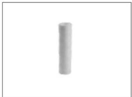
G Disp osable Filter Cartridge, short, for mechanical preliminary filtering of sand.
H Wa shable Filter cartridge, short, for mechanical preliminary filtering of sand, reusable.
I Acti vated Carbon Filter Cartridge, short, for use with chlorous water, removes odours or discolouring.
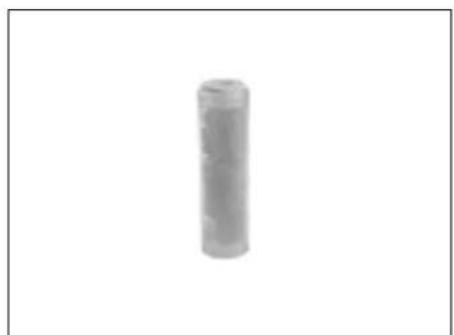
J Fi Iter Cartridge Poly, short, filled with polyphosphate, for calcif-
erous water supplied to water heat-ers.
K Pipe Nipple 150 mm, 1" male at both ends, galvanized, to connect pump and filter.
L Dou ble Nipple, 1" male at boths ends.
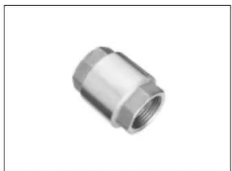
M Check Valve 1" female, prevents water backflow and pump running dry.
N Th read Sealing Tape, 12 m roll.
- Technical Specifications
| P 5500 M | ||
| Mains voltage | V | 230 ~ 1 |
| Frequency Hz 50 | ||
| Rated output W 1500 | ||
| Rated current A 6,7 | ||
| Fuse protection min. (time-lag or L-type circuit breaker) | A | 10 |
| Running capacitor | μF | 20 |
| Rated speed | min^-1 | 2800 |
| Pump capacity max. | l/h | 5500 |
| Delivery head max. | m | 55 |
| Delivery pressure max. | bar | 5,5 |
| Max. suction head | m | 9 |
| Temperature of the primed medium max. | °C | 50 |
| Ambient temperature | °C | 5 ... 40 |
| Degree of protection | IP 44 | |
| Degree of protection | I | |
| Insulation class | F | |
| Materials | ||
| Pump casing | Stainless steel | |
| Pump shaft | Stainless steel | |
| Impeller | Noryl – 5x | |
| Connections (female) | ||
| Pump inlet | 1" | |
| Discharge port | 1" | |
| Dimensions (without connections) | ||
| Length | mm | 480 |
| Width | mm | 245 |
| Height | mm | 300 |
| Weights | ||
| Dry weight | kg | 12,3 |
| Weight filled with water | kg | 14,3 |
| Noise emission values (at max. pressure) | ||
| Sound power level L_WAm | dB (A) | 75 |
| Sound pressure level L_WAd | dB (A) | 78 |
| Max. length of extension cable | ||
| at 3 x 1.0 mm2 lead cross-section | m | 30 |
| at 3 x 1.5 mm2 lead cross-section | m | 50 |
- Pomp verstopt of defect.
- zie hoger.
Druk te laag:
natural_image
Close-up of a mechanical component with coiled tubing and a cylindrical housing (no visible text or symbols)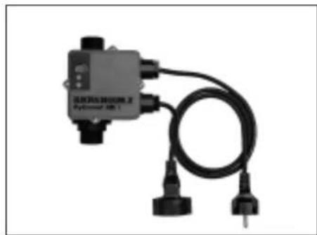
natural_image
Close-up of a black rectangular device labeled 'SINSHROOM.2' connected to two black electrical plugs (no visible text or symbols on the device body)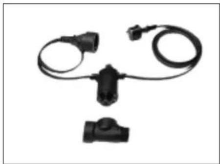
natural_image
Black automotive electrical plug and cable assembly (no text or symbols visible)A 090 304 0521 B 090 304 0424 C 090 305 2597
natural_image
Coiled black electrical plug with a small terminal block, isolated on white background (no text or symbols)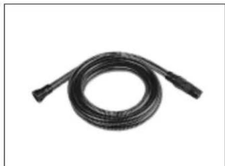
natural_image
Black flexible hose with two connectors, isolated on white background (no text or symbols)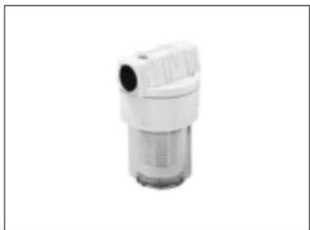
natural_image
White industrial filter or drain component with a cylindrical inlet and side port (no text or symbols visible)D 090 302 8521 E 1) 090 300 4231
2) 090 300 4258
3) 090 301 1858
F 090 305 0314
natural_image
Simple 3D-rendered vertical cylinder on white background (no text or symbols)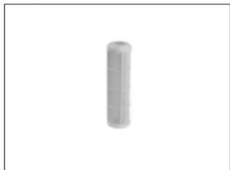
natural_image
Simple 3D-rendered cylindrical object with grid pattern, no text or symbols visible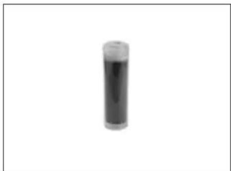
natural_image
Simple black cylindrical object with a lid, isolated on white background (no text or symbols)G 090 302 8432 H 090 302 8440 I 090 302 8475
natural_image
Simple cylindrical object with a flat top, isolated on white background (no text or symbols)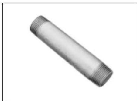
natural_image
Close-up of a metallic pipe fitting with threaded ends (no text or symbols visible)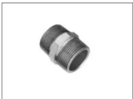
natural_image
Close-up of a metallic threaded pipe fitting (no text or symbols visible)J 090 302 8467 K 090 301 6817 L 090 301 8402
natural_image
Close-up of a metallic pipe fitting with threaded end (no text or symbols visible)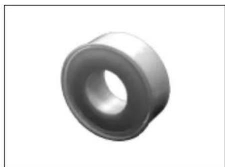
natural_image
3D rendered image of a mechanical bearing or washer (no text or symbols visible)M 090 302 8203 N 090 102 6319


- DE EN
- NL
- Table of Contents
- Please Read First!
- Range of Application and Pumping Media
- Safety
- Specified conditions of use
- General safety instructions
- Hazard by ambient conditions!
- Danger: Hot water!
- Danger! Risk of electric shock!
- Danger by pump failings!
- Caution!
- To avoid water damage, e.g.
- flooded rooms, caused by pump malfunctions or defects:
- Prior to Operation
- Installation
- Suction line connection
- Note:
- Discharge hose connection
- Danger!
- Mains connection
- Filling the pump and priming
- Operation
- Commissioning
- Pump characteristic curve
- Care and Maintenance
- Periodic maintenance
- Danger of freezing
- Equipment dismounting and storing
- Trouble Shooting
- Fault finding
- Pump does not run:
- Pump does not prime correctly or runs very noisily:
- Pressure too low:
- Repairs
- For shipping:
- Environmental Protection
- Available Accessories
- Druk te laag:
Brand : METABO
Model : P 5500 M
Category : Pump