
GS36NVWF0N - Freezer SIEMENS - Free user manual and instructions
Find the device manual for free GS36NVWF0N SIEMENS in PDF.
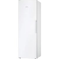


| Product Type | Freezer |
| Brand | Siemens |
| Model | GS36NVWF0N |
| Dimensions (H x W x D) | Approximately 185 x 60 x 65 cm |
| Net Weight | Approximately 75 kg |
| Power Supply | 220-240 V ~ 50 Hz |
| Climate Class | SN-T (ambient temperature from 10 °C to 43 °C) |
| Energy Class | E (according to EU regulation 2019/2016) |
| Annual Energy Consumption | Approximately 250 kWh |
| Freezing Capacity | Approximately 20 kg/24h |
| Power Failure Autonomy | Approximately 24 h |
| Number of Drawers | 6 drawers |
| Interior Lighting | Removable LED |
| Ice Making | Integrated ice maker (removable) |
| Quick Freeze Function | Yes (super freezing) |
| Open Door Alarm | Yes |
| Adjustable Feet | Yes |
| Door Reversibility | Yes (user changeable) |
| Door Gasket | User replaceable |
| Door Handle | User replaceable |
| Hinges | User replaceable |
| Available Spare Parts | Gaskets, handles, hinges, shelves, bins, LED lighting, ice maker |
| Repair Manual | Included in the manual |
Frequently Asked Questions - GS36NVWF0N SIEMENS
User questions about GS36NVWF0N SIEMENS
0 question about this device. Answer the ones you know or ask your own.
Ask a new question about this device
Download the instructions for your Freezer in PDF format for free! Find your manual GS36NVWF0N - SIEMENS and take your electronic device back in hand. On this page are published all the documents necessary for the use of your device. GS36NVWF0N by SIEMENS.
USER MANUAL GS36NVWF0N SIEMENS
4.3 Replacing the easy opening handle 11
4.3.1 Removing the easy opening handle 11 4.3.2 Installing the easy opening handle 11
4.4 Replacing the door panel and the door 12
4.4.1 Removing the door panel 12 4.4.2 Installing the door panel 14
4.5 Replacing the upper door panel (door with display) 15
4.5.1 Removing the door panel 16 4.5.2 Installing the door panel 17
4.6 Replacing the lower door panel 18
4.6.1 Removing the lower door panel 18 4.6.2 Installing the lower door panel 19
4.7 Replacing the handle 20
4.7.1 Removing the handle 20 4.7.2 Installing the handle 20
4.8 Replacing the container for spoiled food products 21
4.8.1 Removing the container for spoiled food products...21 4.8.2 Installing the container for spoiled food products.. 21
4.9 Replacing the dehumidifier 22
4.9.1 Removing the dehumidifier 22 4.9.2 Installing the dehumidifier 22
4.10 Replacing the LED lighting inside
4.10.1 Connecting the LED lighting 23 4.10.2 Mounting the LED lighting from the rear 24
ABOUT THIS DOCUMENT
1.1 Important information
1.1.1 Purpose
This manual is intended to help the user repair the device themselves, in accordance with the regulations for environmentally friendly design of devices (OT03.2021).
It contains information about the replacement of certain spare parts, including fuses and risks.
If you have any questions, please contact our customer service. We are not responsible for damage if the repair instructions have not been followed correctly.
1.2 Explanation of symbols
1.2.1 Danger
Warning: This symbol indicates a hazard. The symbol shows the severity of the danger.
Mounting and handling.

Repair
4.3 Removing the easy opening handle
Special tools:
Cross-head screwdriver PH2
N3nCKBaHe:
YpeBt E n3KIOUeH OT 3aXpaHbAHeTO. BpaTaTa e oTbopeHa.
4.3.1 CbJIHe Ha easy opening handle
- Cibanete kanaeTo Ha easy opening handle (1).
- Pa3BnIe DaBaTa BnHTa (2).
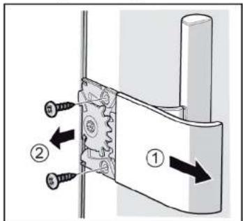
Easy opening handle e cbaneHa.
4.3.2 MoNTIpaHHe Ha easy opening handle
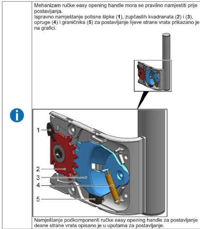
Mexaan3mbt Ha easy opening handle Tpa6ba Da 6bde npabnHn Hactpoen npenMOHTaKa. PpabnHTo paaonooKeHHe ha 6ytaHnna Ppbt (1), HaaBSeHnTe KaanpaTn (2) (3), npyKnHata (4) n orpaHnHnten (5) 3a MoHTax Ha BpTaTaTAt OtnBa e noKa3aHO Ha padkNata.

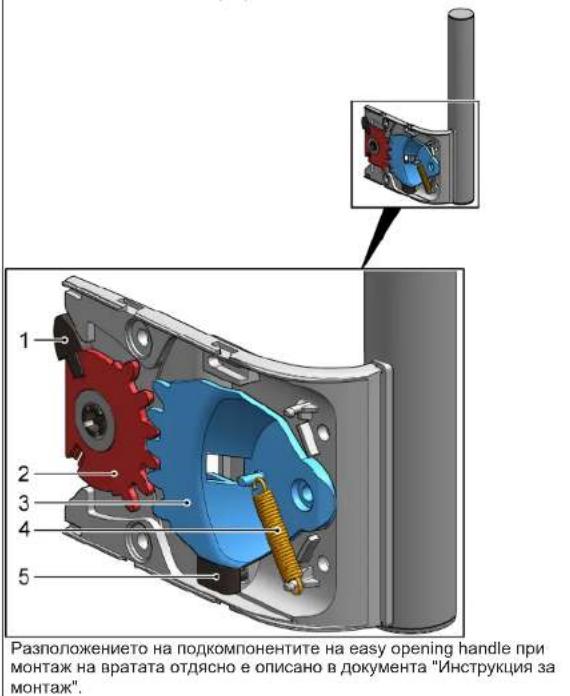
MoHTnpaTBeB6paTeHpei.

PemOH
4.4 CmHa Ha rohata naHt ha BpataTa
CneuaJIHHHCTpymeHTN:
HakpaHHK Torx TX20 6.3 MM (1/4") [00340865]

IPEADYNPEXKDEHNE
Teekn, o6emncTuypeu!
Place the device on the wall of the client, floor.
TS
Secure the component so that it does not fall.
Removal:
The device is equipped with a locking mechanism. The device filters are removed.
4.4.1 Removing and installing the door panels

Repair
- Place the device on the floor of the room.
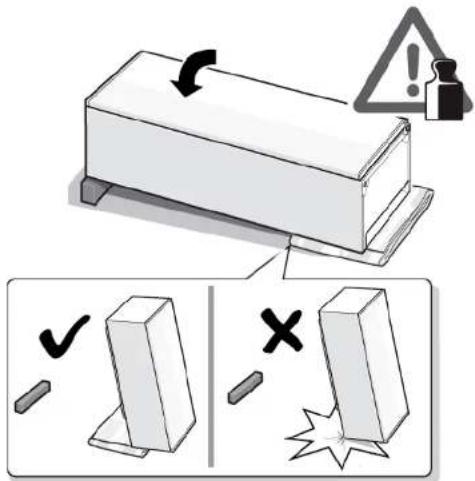
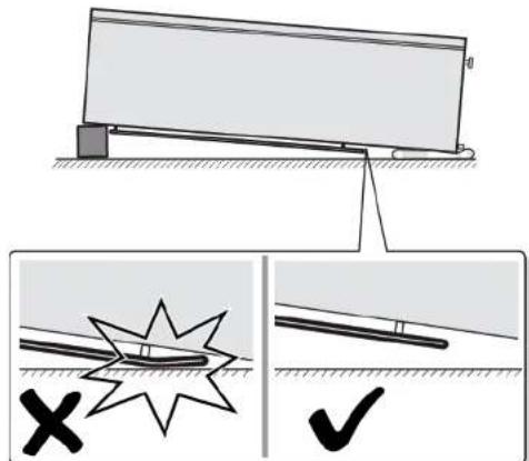
2.1. Press the cable of the upper panel from the side (1).
- Remove the cable of the upper panel (2).
- Press the cable of the upper panel (3).

Repair
3.1. Press the panel (1).
- Press the lower panel (2).
The upper panel of the door is pressed. 4.4.2 Installing the door panel
Mounting the tool.
Special tools:
Torx socket TX20 6.3 mm (1/4") [00340865]
WARNING
Risk of injury!
Injury to muscles or tendons
Improper use or handling of the tool can cause injury. Only qualified personnel should use this tool. Use only appropriate tools and equipment.
CAUTION
Sharp edges!
Risk of cuts
Wear protective gloves.
WARNING
Risk of injury from tool!
Bone fractures/cuts
Secure the tool before use.
Risk of falling parts during screw loosening!
Properly secure the component parts so they do not fall.
WARNING!
Risk of falling parts during screw loosening! Damage to the device or the customer's home may occur. Secure the component so it does not fall.

DANGER
Risk of electric shock from live parts!
Danger of electric shock in case of improper repair. Electrical parts must be repaired by a qualified electrician. After repair, a safety check must be carried out in accordance with VDE 0701 and the national regulations.
DANGER
Risk of electric shock from live parts!
Electric shock
Disconnect the device from the power supply for at least 60 seconds before opening or repairing.
Inspection:
The device is disconnected from the power supply. The device cover has been removed.

Repair
4.5.1 On the door leaf
- The installer must place the door on the opposite side.
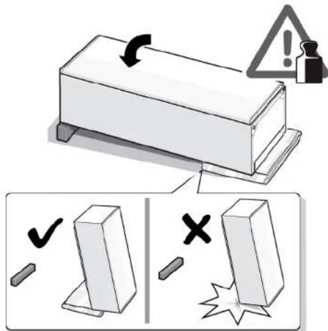
Mounting the return spring.

Repair
4.6 Removing the lower door leaf
Special tools:
Torx screwdriver TX20 6.3 mm (1/4") [00340865]
WARNING
Danger of injury!
Mounting the return spring.

Repair
4.8 Removing the container for contaminated food products
Requirement: The door is open.
4.8.1 Removing the container for contaminated food products
- Pull out the container for contaminated food products (1). 2. Remove the container for contaminated food products (2).
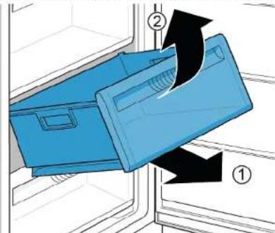
Container for charging and storing products outside.
4.8.2 Installation of containers for charging and storing products
Installation instructions.
Decontaminator outside.
4.9.2 Installation of the decontaminator
Installation instructions.

Repair
4.10 LED lighting signal
Special tools:
Flat screwdriver 2.4mm x 0.4mm x 60mm, in the kit [00341820]

The device is equipped with LED lighting that does not require maintenance. This lighting can be repaired only by specialists from the service department or by qualified technicians.


DANGER
Risk of electric shock from live parts. Danger to life from electric shock in case of improper handling.
Electrical equipment must be repaired by qualified electricians. Before repair, a safety check must be carried out according to VDE 0701 or in accordance with the national regulations.


DANGER
Shock hazard! Risk of electric shock!
Electric shock hazard
Disconnect the appliance from the power supply before cleaning or maintenance.


CAREFULLY
Sharp edges!
Installation
Wear protective gloves.
Removal:
Disconnect the appliance from the power supply. The cover is opened and the inner parts are exposed.
4.10.1 Replacing the LED lighting
- Replace the LED lighting as follows.
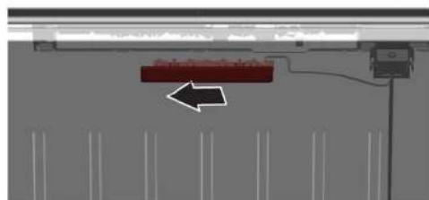
Disconnect the appliance from the power supply and the LED lighting is disconnected.
2. Remove the LED lighting.
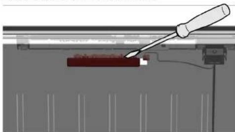

Repair
3. Replace the LED lighting, pressing it into place.
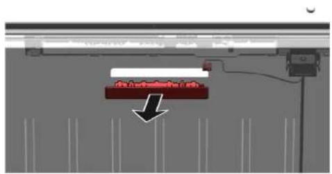
LED lighting installation. 4.10.2 Installation of LED lighting. Before installation, disconnect from power supply.
4.3 Replacing the easy opening handle 34
4.3.1 Removing the easy opening handle 34 4.3.2 Installing the easy opening handle 34
4.4 Replacing the upper door hinge 35
4.4.1 Removing the door hinge 35 4.4.2 Installing the door hinge 37
4.3 Replacing the easy opening handle
Special tools:
Phillips screwdriver PH2
Requirement:
The appliance is disconnected from the power supply. The door is open.
4.3.1 Removing the easy opening handle
- Remove the cover of the easy opening handle (1). 2. Unscrew the two screws (2).
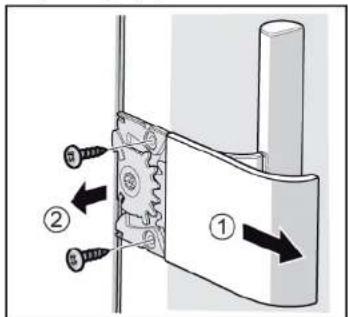

The easy opening handle is removed.
4.3.2 Installing the easy opening handle
4.3 Replacing the easy opening handle 56
4.3.1 Removing the Easy opening handle 56 4.3.2 Installing the Easy opening handle 56
4.4 Replacing the upper door hinge 57
4.4.1 Removing the door hinge 57 4.4.2 Installing the door hinge 59
4.5 Replacing the upper door hinge (door with indicator) 60
4.5.1 Removing the door hinge 61 4.5.2 Installing the door hinge 62
4.6 Replacing the lower door hinge 63
4.6.1 Removing the lower door hinge 63 4.6.2 Installing the lower door hinge 64
4.7 Replacing the shelf 65
4.7.1 Removing the shelf 65 4.7.2 Installing the shelf 65
4.8 Replacing the frozen food storage container 66
4.8.1 Removing the frozen food storage container 66 4.8.2 Installing the frozen food storage container 66
4.9 Replacing the ice maker 67
4.9.1 Removing the ice maker 67 4.9.2 Installing the ice maker 67
4.10 Replacing the LED upper lighting 68
4.3 Replacing the Easy opening handle
Special tools:
Make sure to secure the devices against slipping.

CAUTION
Danger of falling parts due to loose screws!
Risk of injury from falling parts. Make sure to secure the component against falling.

NOTE!
Danger of falling parts due to loose screws!
Make sure to secure the component against falling.
Presetting:
Make sure to secure the devices against slipping.


CAUTION
Danger of falling parts due to loose screws!
Risk of injury from falling parts. Make sure to secure the component against falling.

NOTE!
Danger of falling parts due to loose screws!
Secure the component to prevent it from falling.


DANGER
Secure the appliances to prevent them from slipping.

CAUTION
Risk of falling parts due to loose screws!
Risk of injury from falling parts. Secure the component to prevent it from falling.

NOTE!
Risk of falling parts due to loose screws!
Secure the component to prevent it from falling.
Presetting:
Repair hints - Freezer
1 Concerning this document. 116
1.1 Important information 116
1.1.1 Purpose 116 1.2 Explanation of symbols 116 1.2.1 Danger levels 116 1.2.2 Hazard symbols 116 1.2.3 Structure of the warnings 117 1.2.4 General symbols 117
Safety. 118
2.1 General Safety instructions 118
2.1.1 All domestic appliances 118
Tools and aids. 119
Repair 120
4.3 Replacing easy opening handle 124
4.3.1 Removing easy opening handle 124 4.3.2 Installing easy opening handle 124
4.4 Replacing door upper hinge 125
4.5 Replacing door upper hinge (door with display) 128
4.7 Replacing shelf. 133
4.7.1 Removing shelf 133 4.7.2 Installing shelf 133
4.8 Replacing frozen food container. 134
4.8.1 Removing frozen food container 134 4.8.2 Installing frozen food container 134
4.9 Replacing ice maker 135
4.9.1 Removing ice maker 135 4.9.2 Installing ice maker 135
4.10 Replacing LED top light 136
4.10.1 Removing LED light. 136 4.10.2 Installing top LED light 137
Concerning this document
1.1 Important information
1.1.1 Purpose
These repair hints support consumers in repairing appliances themselves, in accordance with the applicable eco-design regulation (as of 03/2021).
They contain information on how to exchange defined spare parts, including warnings and risks.
In case of questions, please contact our customer service. We will only be liable for damages if the repair hints have been followed properly.
1.2 Explanation of symbols
1.2.1 Danger levels
The warning levels consist of a symbol and a signal word. The signal word indicates the severity of the danger.
| Warning level Meaning | |
| Danger | Non-observation of the warning message will result in death or serious injuries. |
| Warning | Non-observation of the warning message could result in death or serious injuries. |
| Caution | Non-observation of the warning message could result in minor injuries. |
| Notice | Non-observation of the warning message could result in damage to property. |
Table 1: Danger levels
1.2.2 Hazard symbols
Hazard symbols are symbolic representations that give an indication of the kind of danger.
The following hazard symbols are used in this document:
| Hazard symbol Meaning | |
| ! | General warning message |
| Danger from electrical voltage | |
| Risk of explosion | |
| Danger of cuts | |
| Danger of crushing |
Concerning this document
| Hazard symbol Meaning | |
| Danger from hot surfaces | |
| Danger from strong magnetic field | |
| Danger from non-ionizing radiation |
Table 2: Hazard symbols
1.2.3 Structure of the warnings
Warnings in this document have a standardized appearance and structure.
Danger
Type and source of danger!
Possible consequences of ignoring the danger/warning.
Measures and prohibitions for preventing the danger.
The following example shows a warning that warns against electric shock due to live parts. The measure for avoiding the danger is mentioned.
Danger
Risk of electric shock due to live parts!
Death by electrocution
- Disconnect appliances from electrical supply at least 60 seconds before starting repairs.
1.2.4 General symbols
The following general symbols are used in this document:
| Gen. symbol Meaning | |
| 1 | Identification of a special tip (text and/or graphic) |
| i | Identification of a simple tip (only text) |
| Identification of a link to a video tutorial |
Table 3: General symbols
| Gen. symbol Meaning | |
| Identification of required tools | |
| Identification of required preconditions | |
| Identification of a condition (if ..., then ...) | |
| Identification of a result | |
| [Start] Identification of a key or button | |
| [00123456] Identification of a material number | |
| Status Identification of displayed text / window(in the appliance's display) | |
Safety
2.1 General Safety Instructions
2.1.1 All Domestic Appliances
Risk of electric shock due to live parts!
Errors by repairs involving electrical components can lead to electrical shock! - Disconnect the appliance from the mains for at least 60 seconds before starting work. After the repair, have a safety test performed according to VDE 0701 or country-specific regulations.
Risk of injury from sharp edges!
Wear protective gloves.
Risk of crushing during repair, maintenance, troubleshooting and service due to heavy and moving components.
Wear protective shoes. - Secure heavy components from falling down. - Do not stick body parts into moving components.
Risk to the appliance's safety / function! Only use original spare parts. Risk of damage to electrostatically sensitive components (ESDs)! - Do not touch the modules, including connections and conductor paths.

Tools and Aids
| Designation Details Images | ||
| Protection cloth [00342013] | 60 cm x 50 cm | ### |
| Phillips screwdriver PH2 | ||
| Torr Bit TX20 [00340865] | 6.3 mm (1/4") | |
| Slotted screwdriver | Blade 2.4 mm x 0.4 mm x 60 mm, in the kit [00341820] | ① |
Prerequisite: Door is open.
- Release door gasket from the groove on right and left corner.
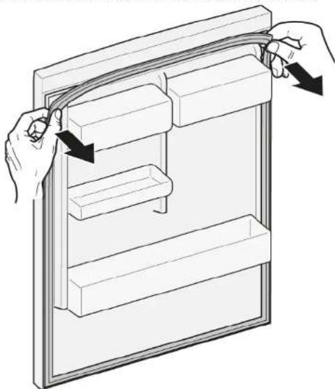
- Pull out door gasket from groove.
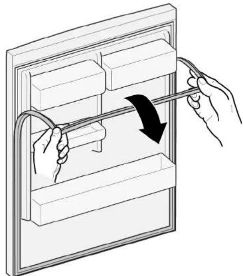

Door gasket is removed.
| Thickness of new door gasket may deviate slightly from thickness of old door gasket. This will not affect closing behavior and long-term function. | |
| If your appliance has adjustable hinges or hinge attachments, you can optimize the closing behavior subsequently. | |
| Small side holes in door gasket are functional (required for ventilation). These are not production faults. |

Repair
- Check groove for gasket for damage.
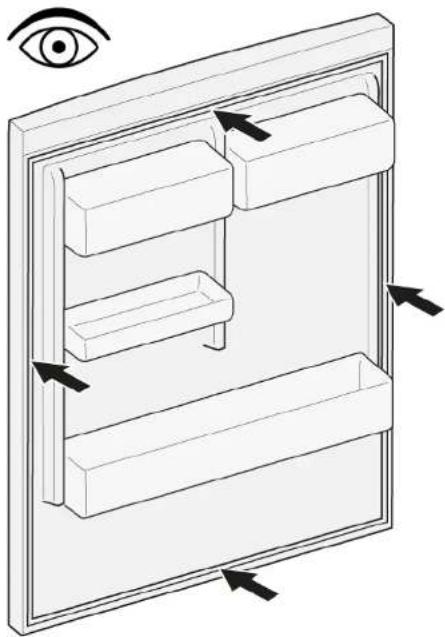
- If groove for gasket is damaged.
- Contact customer service.
- Slight deformation of door gasket is normal and does not affect its function. It is recommended to straighten door gasket before inserting it into appliance.
Heat door gasket with a hair dryer or hot water and manually reshape it.
- Push corners of gasket at the top and bottom to the groove.
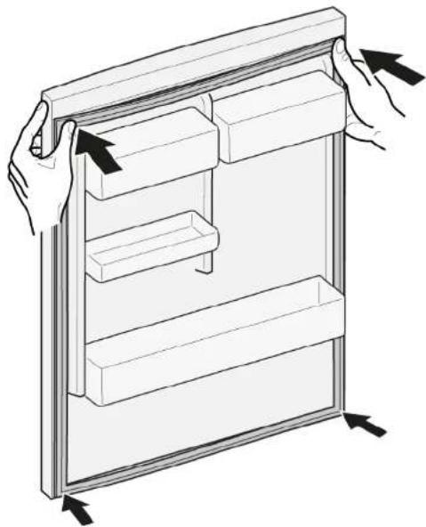

Repair
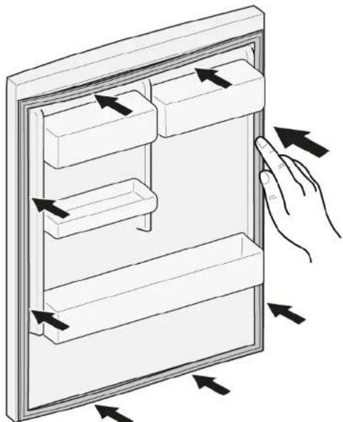
- Press whole gasket step by step into the groove.
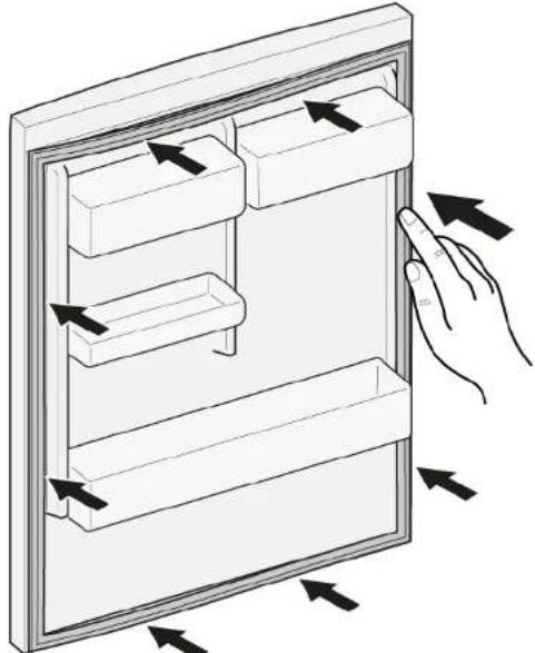

Door gasket is installed.
Slotted screwdriver Blade 10 mm x 1.6 mm x 200 mm
Prerequisite:
① Appliance is disconnected from power supply. Door is open.
4.2.1 Removing door handle
- Remove two screw caps (1).
- Unscrew two screws (2).
- Remove door handle (3).
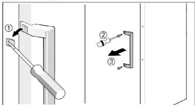

Door handle is removed.
Install in reverse order.

Repair
4.3 Replacing easy opening handle
Required tools:
Phillips screwdriver PH2 Prerequisite: Appliance is disconnected from power supply. Door is open.
4.3.1 Removing easy opening handle
- Remove easy opening handle cover (1).
- Unscrew two screws (2).
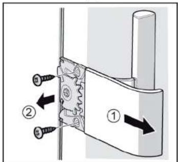

Easy opening handle is removed.
4.3.2 Installing easy opening handle
Install in reverse order.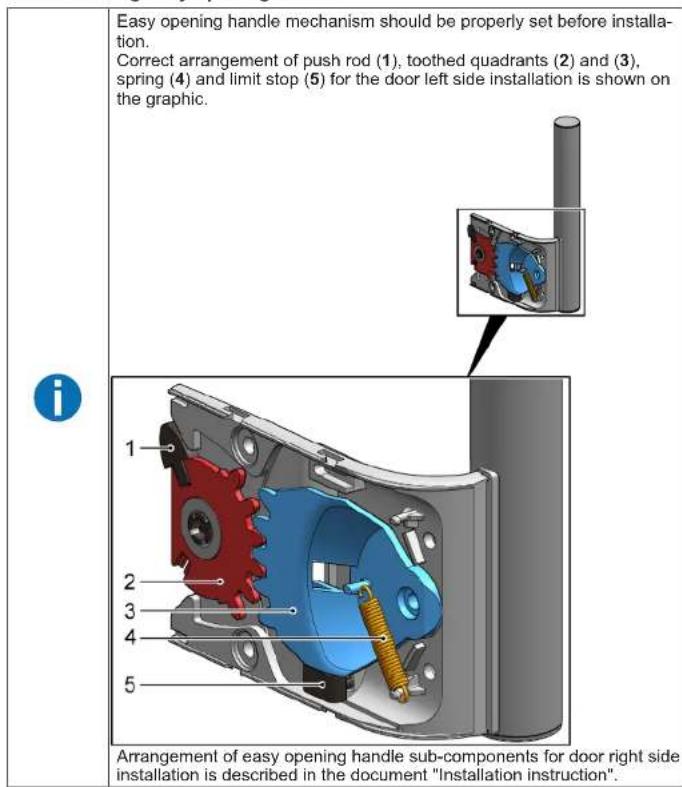

Repair
4.4 Replacing door upper hinge
Required tools:
Torx Bit TX20 6.3 mm (1/4") [00340865]

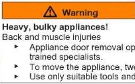
Heavy, bulky appliances!
Back and muscle injuries
- Appliance door removal operation should only be carried out by trained specialists. To move the appliance, two people are required. Use only suitable tools and equipment.


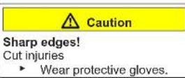
Sharp edges!
Cut injuries
Wear protective gloves.

Slipping of tilted appliances!
Bone fractures / crush injuries
Secure appliances against slipping

Risk of falling parts due to released screws!
ury because of falling parts.
- Secure component from falling down.

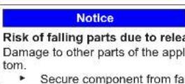
Risk of falling parts due to released screws!
Damage to other parts of the appliance or at customers home e.g. bot
tom.
- Secure component from falling down.
Prerequisite:
Appliance is disconnected from power supply. Appliance interior fittings are removed.
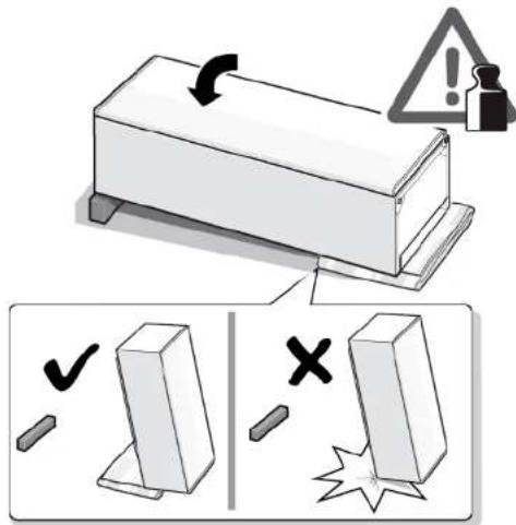
- Place appliance on the back side.
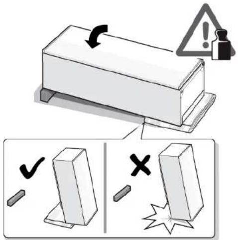
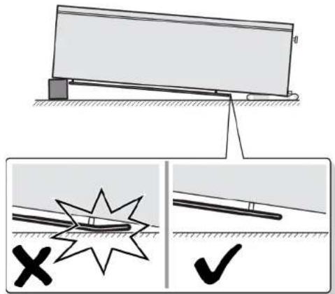
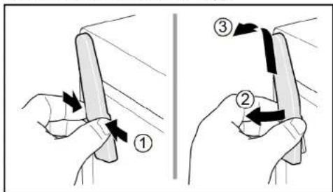
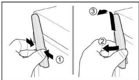
2.1. Press upper hinge cover on both sides (1).
- Move out upper hinge cover (2).
- Remove upper hinge cover (3).

Repair
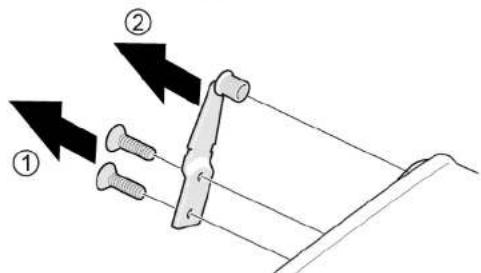
3.1. Unscrew two screws (1).
- Remove upper hinge (2).
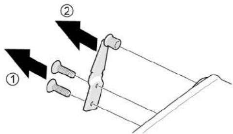
Door upper hinge is removed. 4.4.2 Installing door hinge Install in reverse order.

Repair
4.5 Replacing door upper hinge (door with display)
Required tools:
Torx Bit TX20 6,3 mm (1/4") [00340865]

Warning
Heavy, bulky appliances!
Back and muscle injuries
Appliance door removal operation should only be carried out by trained specialists. To move the appliance, two people are required. Use only suitable tools and equipment.

Caution
Sharp edges!
Cut injuries
Wear protective gloves.
Warning
Slipping of tilted appliances!
Bone fractures / crush injuries
- Secure appliances against slipping

Caution
Risk of falling parts due to released screws!
Injury because of falling parts.
Secure component from falling down.
Notice
Risk of falling parts due to released screws!
Damage to other parts of the appliance or at customer's home e.g. bottom.
Secure component from falling down.
- Danger
Risk of electric shock due to live parts!
Danger to life through electric shock in case of improper repair.
Danger to life through electric shock in case of improper repair
Electric parts should be repaired by a qualified electrician.
After the repair, have a safety test performed according to VDE 0701 or country-specific regulations.
Danger
Risk of electric shock due to live parts!
Death by electrocution
- Disconnect appliances from the electrical supply at least 60 seconds before starting repairs.
Prerequisite:
1. Appliance is disconnected from power supply. 2. Appliance interior fittings are removed.

Repair
- Place appliance on its back side.

Repair
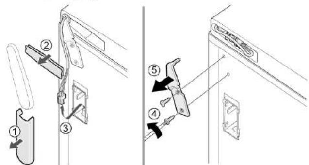
1. Press upper hinge cover on both sides (1). 2. Move out upper hinge cover (2). 3. Remove upper hinge cover (3).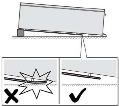
1. Remove cable box cover (1). 2. Remove cable protection (2). 3. Disconnect electrical connection (3). 4. Unscrew two screws (4). 5. Remove upper hinge (5).
Door upper hinge is removed.
Install in reverse order.

Repair
4.6 Replacing door lower hinge
Required tools:
Torx Bit TX20 6.3 mm (1/4") [00340865]
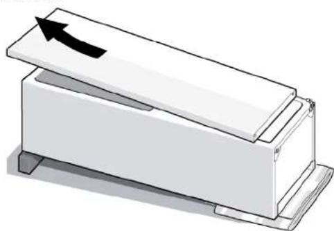
Prerequisite:
Appliance is disconnected from power supply. Appliance interior fittings are removed. Appliance is placed on the back side.

Upper hinge is removed. See page 128.
4.6.1 Replacing door lower hinge
- Remove door.
2.1. Unscrew the screw (1).
- Turn lower hinge out (2).
- Remove lower hinge (3).
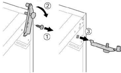

Lower hinge is removed.

Repair
Install in reverse order.

Repair
4.7 Replacing shelf
Prerequisite: Door is open.
4.7.1 Removing shelf
Pull out shelf.
Shelf is removed.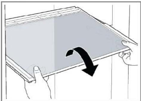
4.7.2 Installing shelf
Install in reverse order.

Repair
4.8 Replacing frozen food container
Prerequisite: Door is open.
4.8.1 Removing frozen food container
- Pull out frozen food container all the way (1). 2. Remove frozen food container (2).
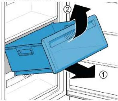
Frozen food container is removed.
4.8.2 Installing frozen food container
Install in reverse order.

Repair
4.9 Replacing ice maker
Prerequisite: Door is open.
4.9.1 Removing ice maker
- Pull out shelf frozen food container with ice maker (1).
- Release hooks (2).
- Remove ice maker (3).
Ice maker is removed.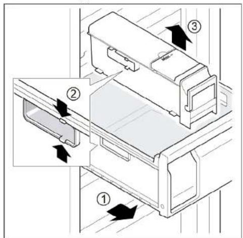
4.9.2 Installing ice maker
Install in reverse order.

Repair
4.10 Replacing LED top light
Required tools:
Slotted screwdriver Blade 2.4 mm x 0.4 mm x 60 mm, in the kit [00341820]

Your appliance features a maintenance-free LB
These lights may be repaired by customer service or authorized technicians only!

Danger
Risk of electric shock due to live parts!
Danger to life through electric shock in case of improper repair
Electric parts should be repaired by a qualified electrician.
After the repair, have a safety test performed according to VDE 0701 or country-specific regulations.

Danger
Risk of electric shock due to live parts!
Death by electrocution
- Disconnect appliances from electrical supply at least 60 seconds before starting repairs.


Caution
Sharp edges!
Cut injuries
Wear protective gloves.
Prerequisite:
Appliance is disconnected from power supply. Door is open. Upper interior fittings are removed.
4.10.1 Removing LED light
- Move the LED light to the left side.
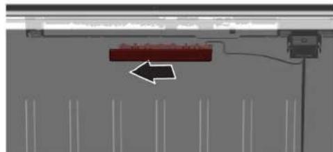
LED light electrical connection is disconnected.
- Release LED light hooks.
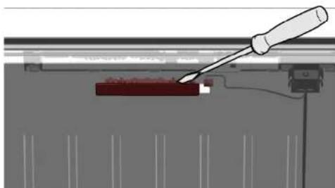

Repair
- Remove LED light moving it forward.
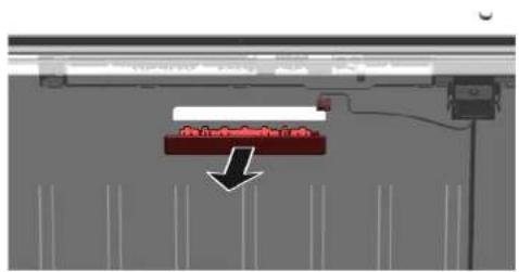
LED light is removed. 4.10.2 Installing top LED light Install in reverse order.
Remonditeave - Sögavkülmik
1 Regarding this document 139
1.1 Important information 139
1.1.1 Purpose 139 1.2 Explanation of symbols 139 1.2.1 Hazard levels 139 1.2.2 Hazard symbols 139 1.2.3 Structure of warnings 140 1.2.4 General symbols 140
Safety. 141
2.1 General safety instructions 141 2.1.1 All household appliances 141
Table 1: Safety devices
1.2.2 Ohusumbolid
Therefore m = 3/11 ;
DANGER
Therefore m = 3/11 ;
Risk of electric shock due to live parts!
4.3 Replacing the easy opening handle 418
4.3.1 Removing the easy opening handle 418 4.3.2 Installing the easy opening handle 418
4.4 Replacing the top door hinge 419
4.4.1 Removing the door hinge 419 4.4.2 Installing the door hinge 421
4.5 Replacing the top hinge (door or display) 422
4.5.1 Removing the hinge 423 4.5.2 Installing the door hinge 424
4.6 Replacing the bottom hinge 425
4.6.1 Replacing the bottom hinge 425 4.6.2 Installing the bottom hinge 426
Torx TX20 screwdriver 6.3 mm (1/4") [00340865]
Flathead screwdriver Blade 10 mm x 1.6 mm x 200 mm
Requirement:
4.3 Replacing the easy opening handle
Special tools:
Phillips screwdriver PH2. Requirement: The appliance is disconnected from the power supply. The door is open.
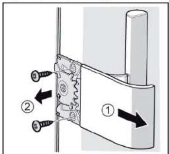
4.3.1 Removing the easy opening handle
- Remove the easy opening handle (1).
- Unscrew the two screws (2).

Torx TX20 6.3 mm (1/4") socket [00340865]

WARNING
Heavy, bulky appliances!
Risk of back injury and muscle strain
Torx TX20 6.3 mm (1/4") socket [00340865]

WARNING
Heavy, bulky appliances!
Risk of back injury and muscle strain
Cap torx TX20 6.3 mm (1/4") [00340865]

WARNING
Heavy, massive appliances!
Back injury and muscle strain
4.3 Replacing the easy opening handle 441
4.3.1 Removing the easy opening handle 441 4.3.2 Installing the easy opening handle 441
4.4 Replacing the upper door hinge 442
4.4.1 Removing the door hinge 442 4.4.2 Installing the door hinge 444
4.3 Replacing the easy opening handle
Special tools:
4.3 Replacing the easy opening handle 509
4.3.1 Removing the easy opening handle 509 4.3.2 Installing the easy opening handle 509
- Press the entire gasket into the groove bit by bit.

4.3 Replacing the easy opening handle
Required tools:
Phillips screwdriver PH2
Prerequisite:
The appliance is disconnected from the power supply. The door is open.
4.3.1 Removing the Easy opening handle
- Remove the cover for the Easy opening handle (1).
- Unscrew the two screws (2).
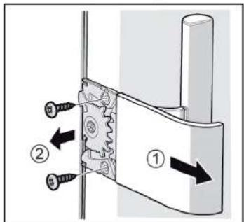

The Easy opening handle has been removed.
4.3.2 Installing the Easy opening handle
- ABOUT THIS DOCUMENT
- IMPORTANT INFORMATION
- PURPOSE
- EXPLANATION OF SYMBOLS
- DANGER
- REPAIR
- REMOVING THE EASY OPENING HANDLE
- CBJIHE HA EASY OPENING HANDLE
- MONTIPAHHE HA EASY OPENING HANDLE
- PEMOH
- CMHA HA ROHATA NAHT HA BPATATA
- IPEADYNPEXKDEHNE
- REMOVING AND INSTALLING THE DOOR PANELS
- WARNING
- CAUTION
- REMOVING THE LOWER DOOR LEAF
- REMOVING THE CONTAINER FOR CONTAMINATED FOOD PRODUCTS
- INSTALLATION OF CONTAINERS FOR CHARGING AND STORING PRODUCTS
- INSTALLATION OF THE DECONTAMINATOR
- LED LIGHTING SIGNAL
- CAREFULLY
- REPLACING THE LED LIGHTING
- REPLACING THE EASY OPENING HANDLE
- INSTALLING THE EASY OPENING HANDLE
- NOTE
- PRESETTING
- REPAIR HINTS - FREEZER
- CONCERNING THIS DOCUMENT
- DANGER LEVELS
- HAZARD SYMBOLS
- STRUCTURE OF THE WARNINGS
- GENERAL SYMBOLS
- SAFETY
- GENERAL SAFETY INSTRUCTIONS
- ALL DOMESTIC APPLIANCES
- TOOLS AND AIDS
- REMOVING DOOR HANDLE
- REPLACING EASY OPENING HANDLE
- REMOVING EASY OPENING HANDLE
- INSTALLING EASY OPENING HANDLE
- REPLACING DOOR UPPER HINGE
- REPLACING DOOR UPPER HINGE (DOOR WITH DISPLAY)
- NOTICE
- RISK OF ELECTRIC SHOCK DUE TO LIVE PARTS
- REPLACING DOOR LOWER HINGE
- REPLACING SHELF
- REMOVING SHELF
- INSTALLING SHELF
- REPLACING FROZEN FOOD CONTAINER
- REMOVING FROZEN FOOD CONTAINER
- INSTALLING FROZEN FOOD CONTAINER
- REPLACING ICE MAKER
- REMOVING ICE MAKER
- INSTALLING ICE MAKER
- REPLACING LED TOP LIGHT
- REMOVING LED LIGHT
- REMONDITEAVE - SÖGAVKÜLMIK
- OHUSUMBOLID
Brand : SIEMENS
Model : GS36NVWF0N
Category : Freezer