
AM540 - Multimeter FLUKE - Free user manual and instructions
Find the device manual for free AM540 FLUKE in PDF.
User questions about AM540 FLUKE
0 question about this device. Answer the ones you know or ask your own.
Ask a new question about this device
Download the instructions for your Multimeter in PDF format for free! Find your manual AM540 - FLUKE and take your electronic device back in hand. On this page are published all the documents necessary for the use of your device. AM540 by FLUKE.
USER MANUAL AM540 FLUKE
Limited Warranty and Limitation of Liability
Your Beha-Amprobe product will be free from defects in material and workmanship for three years from the date of purchase unless local laws require otherwise. This warranty does not cover fuses, disposable batteries or damage from accident, neglect, misuse, alteration, contamination, or abnormal conditions of operation or handling. Resellers are not authorized to extend any other warranty on the behalf of Beha-Amprobe. To obtain service during the warranty period, return the product with proof of purchase to an authorized Beha-Amprobe Service Center or to an Beha-Amprobe dealer or distributor. See Repair Section for details. THIS WARRANTY IS YOUR ONLY REMEDY. ALL OTHER WARRANTIES - WHETHER EXPRESS, IMPLIED OR STATUTORY - INCLUDING IMPLIED WARRANTIES OF FITNESS FOR A PARTICULAR PURPOSE OR MERCHANTABILITY, ARE HEREBY DISCLAIMED. MANUFACTURER SHALL NOT BE LIABLE FOR ANY SPECIAL, INDIRECT, INCIDENTAL OR CONSEQUENTIAL DAMAGES OR LOSSES, ARISING FROM ANY CAUSE OR THEORY. Since some states or countries do not allow the exclusion or limitation of an implied warranty or of incidental or consequential damages, this limitation of liability may not apply to you.
Repair
All Beha-Amprobe tools returned for warranty or non-warranty repair or for calibration should be accompanied by the following: your name, company's name, address, telephone number, and proof of purchase. Additionally, please include a brief description of the problem or the service requested and include the test leads with the meter. Non-warranty repair or replacement charges should be remitted in the form of a check, a money order, credit card with expiration date, or a purchase order made payable to Beha-Amprobe.
In-Warranty Repairs and Replacement – All Countries
Please read the warranty statement and check your battery before requesting repair. During the warranty period, any defective test tool can be returned to your Amprobe distributor for an exchange for the same or like product. Please check the "Where to Buy" section on amprobe.com for a list of distributors near you. Additionally, in the United States and Canada, in-warranty repair and replacement units can also be sent to an Amprobe Service Center (see address below).
Non-warranty Repairs and Replacement – Europe
European non-warranty units can be replaced by your Beha-Amprobe distributor for a nominal charge. Please check the "Where to Buy" section on beha-amprobe.com for a list of distributors near you.
Beha-Amprobe
Division and reg. trademark of Fluke Corp. (USA)
Germany* United Kingdom The Netherlands - Headquarters**
In den Engematten 14 52 Hurricane Way Science Park Eindhoven 5110
79286 Glottertal Norwich, Norfolk 5692 EC Son
Germany NR6 6JB United Kingdom The Netherlands
Phone: +49 (0) 7684 8009 - 0 Phone: +44 (0) 1603 25 6662 Phone: +31 (0) 40 267 51 00
beha-amprobe.de
beha-amprobe.com
beha-amprobe.com
*(Correspondence only – no repair or replacement available from this address. European customers please contact your distributor.)
**single contact address in EEA Fluke Europe BV
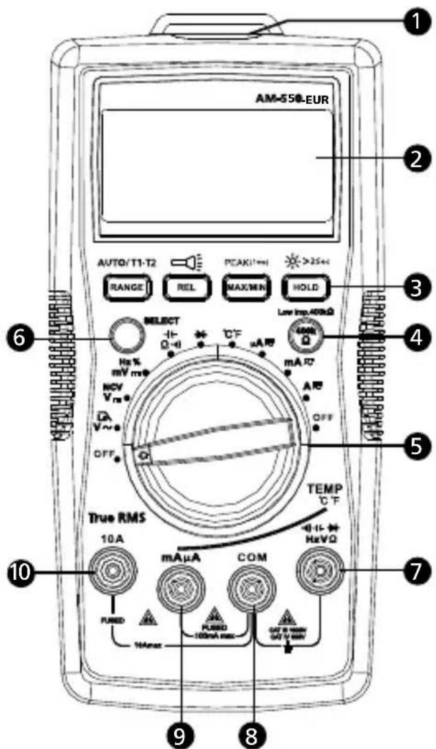
1 Flash light
② LCD Display
3 Push buttons (See making measurement for button functions)
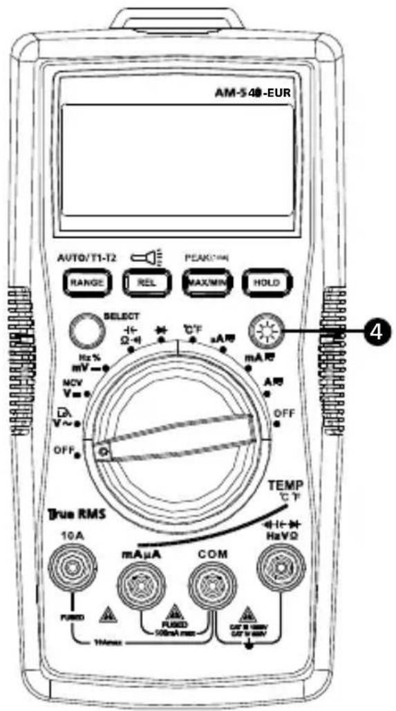
4 AM-550-EUR: Low-impedance button
AM-540-EUR: Backlight button
5 Rotary switch
6 SELECT button
⑦ Input terminal for voltage, diode, capacitance, resistance, continuity and temperature measurement
8 COM (return) terminal for all measurements
9 Input terminal for AC/DC mA/uA measurement
10 Input terminal for AC/DC A measurement to 10A
Screen Display
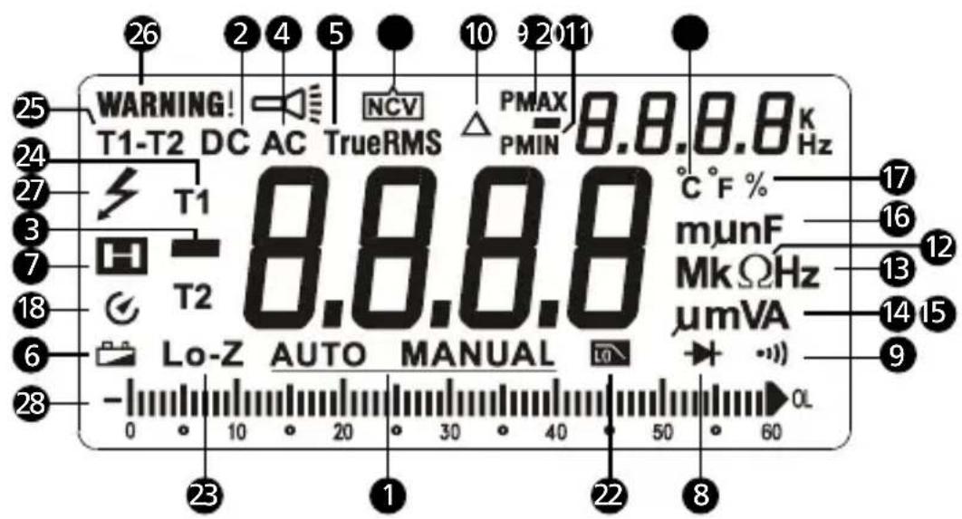
1 Auto- or Manual- range
2 Direct current
3 Negative reading
4 Alternate current
5 True-rms value
6 Low battery indicator
7 Data hold
8 Diode test
9 Continuity test
10 Relative zero mode
11 Non-contact Voltage detection mode
12 Measurement units for Resistance
13 Measurement units for Frequency
15 Measurement units for Current
14 Measurement units for Voltage
16 Measurement units for Capacitance
17 Duty cycle
18 Auto power off
19 Maximum / minimum reading memory
20 Positive / negative peak reading memory
21 Measurement unit for temperature
22 Low-pass filter
23 400KΩ low-impedance test (AM-550-EUR only)
24 Temperature measurement T1 or T2
25 Temperature measurement T1 - T2
26 Warning for error input terminals connection for test leads
27 Hazardous Voltage presence
28 Analog bar graph display
CONTENTS
SYMBOL....2
SAFETY INFORMATION ......2
UNPACKING AND INSPECTION ....3
FEATURES....4
MAKING MEASUREMENT ....5
Rotary Switch Positions 6
Function Buttons ....6
Measuring AC and DC Voltage 9
Low Pass Filter....9
Measuring Frequency / Duty Cycle....11
Measuring AC and DC Current 13
Measuring Resistance ....14
Measuring Continuity ....15
Measuring Capacitance 16
Measuring Diode....17
Measuring Temperature °C / °F 18
Non-Contact Voltage Detection....19
SPECIFICATIONS ....20
MAINTENANCE....24
BATTERY AND FUSE REPLACEMENT....25
SYMBOLS
 | Caution! Risk of electric shock. |
 | Caution! Refer to the explanation in this manual |
 | Alternating Current (AC) |
 | Direct Current (DC) |
 | The equipment is protected by double insulation or reinforced insulation |
 | Earth ground |
 | Audible tone |
 | Battery |
 | Complies with European directives |
 | Conforms to relevant Australian standards |
 | Canadian Standards Association (NRTL/C) |
 | Do not dispose of this product as unsorted municipal wasteContact a qualified recycler |
SAFETY INFORMATION
The meters comply with:
IEC/EN 61010-1 3rd Edition Pollution Degree 2, Measurement Category IV 600V and Measurement Category III 1000V
IEC/EN 61010-2-31 for test leads
EMC IEC/EN 61326-1
Measurement Category IV (CAT IV) is for measurements performed at the source of the low-voltage installation. Examples are electricity meters and measurements on primary overcurrent protection devices and ripple control units.
Measurement Category III (CAT III) is for measurements performed in the building installation. Examples are measurements on distribution boards,
circuit-breakers, wiring, including cables, bus-bars, junction boxes, switches, socket-outlets in the fixed installation, and equipment for industrial use and some other equipment, for example, stationary motors with permanent connection to the fixed installation.
⚠️ WARNING: Read before using
- To avoid possible electrical shock or personal injury, follow these instructions and use the Meter only as specified in this manual.
- Do not use the Meter or test leads if they appear damaged, or if the Meter is not operating properly. If in doubt, have the Meter serviced.
• Always use the proper function and range for measurements. - Before rotating the function range selection switch, disconnect test probe from circuit under test.
- Verify the Meter's operation by measuring on a known voltage source.
- Do not apply more than the rated voltage, as marked on the Meter, between the test probe or between any test probe and earth ground.
- Use the Meter with caution for voltages above 30 V ac rms, 42 V ac peak, or 60 Vdc. These voltages pose electrical shock hazards.
- Disconnect circuit power and discharge all high-voltage capacitors before testing resistance.
- Do not use the Meter around explosive gas or vapor.
- When using the test leads, keep your fingers behind the finger guards.
UNPACKING AND INSPECTION
Your shipping carton should include:
1 AM-540-EUR or AM-550-EUR Multimeter
1 Pair of test leads
2 Temperature probes
1 Temperature adaptor
1 Velcro strap
1 9V (6F22) battery (installed)
1 Users manual
1 Carrying case
If any of the items are damaged or missing, return the complete package to the place of purchase for an exchange.
FEATURES
The multimeter designed for professional HVAC technicians. The AM-540-EUR measures a complete range of electrical parameters and features. Key functions include: temperature, capacitance to check the motor startup capacitors, micro amps for flame sensor troubleshooting, and a low pass filter to take accurate measurements on variable frequency drives. With a built-in flashlight, and non-contact voltage detection, the AM-540-EUR is the choice multimeter for the professional HVAC technician. This meter is safety rated to CAT IV 600V and CAT III 1000V for the most advanced HVAC troubleshooting needs.
The Amprobe AM-550-EUR is a fully featured multimeter designed for professional electricians who need to maintain service or troubleshoot advanced electrical systems. True-rms sensing accurately measures voltage on systems affected by harmonics; built-in flashlight allows you to identify wires while working in dark conditions, and non-contact voltage detection allows for quick go-no-go checks without the need for an additional tool. The AM-550-EUR also features dual input temperature measurement, a low-impedance function to detect stray voltage, and a low pass filter to accurately take measurements on variable frequency drives. Safety rated to CAT IV 600V and CAT III 1000V for use in the most industrial applications.
- Measurements: AC/DC Voltage up to 1000V, ac/dc current, Resistance, Frequency, Capacitance, Temperature, duty cycle.
-
Special Functions:
-
Low Z - to detect "ghost" voltages (for AM-550-EUR only)
- Low pass filter for variable frequency drives
- Non-contact Voltage detection
- Audible continuity
-
Diode test
-
Dual reading backlit LCD display with analog bargraph
-
Events:
-
Data hold
- MAX / MIN memory
- Peak hold (crest)
- Relative zero mode
• Built-in flash light
- Built-in test leads storage and "third hand holder"
- Warning against improper test leads connection
• Auto and manual ranging
- Auto power off
- Low battery warning
- Velcro strap to hang a meter
• Safety: CAT IV 600V, CAT III 1000V
MAKING MEASUREMENT
△️ △️
- Use the proper function and range for measurements.
- To avoid possible electrical shock, personal injury or damages to the Meter, disconnect circuit power and discharge all high-voltage capacitors before testing resistance and diode.
-
Connecting test leads:
-
Connect the common (COM) test lead to the circuit before connecting the live lead;
• After measurement, remove live lead before removing the common (COM) test lead from the circuit -
Symbol "OL" is displayed on LCD when the measurement is out of range.
Rotary Switch Positions
| Switch Position M | Measurement Function |
| V / | AC voltage measurement / Low-pass filter (1kHz).Use SELECT button to select alternate function. |
| V_== / NCV | DC voltage measurement / Non-contact Voltage detection. Use SELECT button to select alternate function. |
| mV_m /Hz % | DC millivolt measurement / Frequency / Duty cycleUse SELECT button to select alternate function. |
| / -1(-·s) | Resistance / Capacitance / Continuity measurement.Use SELECT button to select alternate function. |
| Voltage measurement of diode PN junction (diode test). | |
| °C °F | Temperature measurement.Use SELECT button to select temperature unit °C or °F. |
| μA∞ mA∞10A∞ | AC or DC current measurement.Use SELECT button to select alternate function ac or dc |
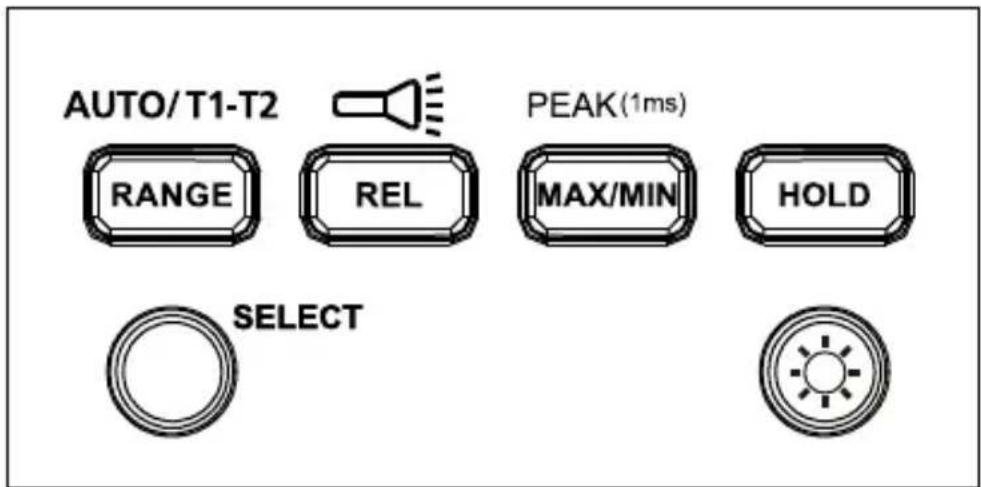
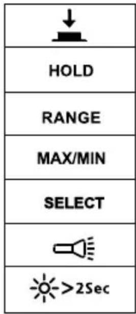
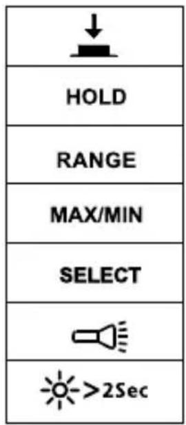
AM-540-EUR Function Buttons
| Button Measurement Function | |
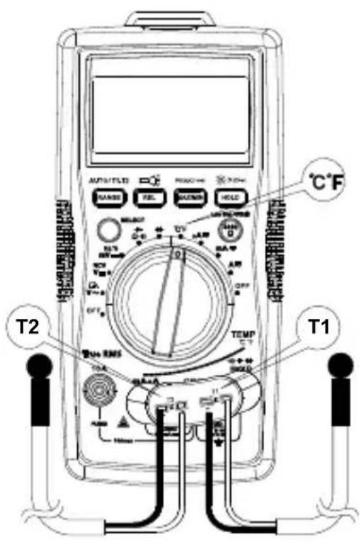
| SELECT | Press the yellow SELECT button to select alternate measurement functions on the rotary switch. |
| RANGE / AUTO T1-T2 | Manual or Auto range switching for voltage current, resistance and capacitance. The default setting is auto-ranging, press to switch to manual ranging. Press for 2 seconds to return to auto-ranging.T1 or T2 or T1-T2 function switching for temperature measurement. |
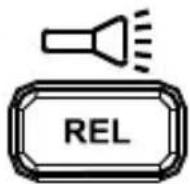
| REL / [IMAGE] | Relative mode △ Press >2 seconds to turn ON or turn OFF flash light. |
| MAX/MIN / PEAK(1ms) | Press to enter maximum / minimum reading memory mode. Press again for maximum reading; press again for minimum reading. Press >2 seconds to exit maximum/minimum reading mode.Press >2 seconds to enter Peak MAX/ Peak MIN mode. Press again for Peak MAX reading; press again for Peak MIN reading. Press >2 sec to exit Peak MAX/ Peak MIN reading mode. |
| HOLD Display | freezes present reading. |
 | Press >2 seconds to turn ON or turn OFF LCD backlight. |
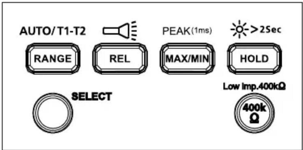
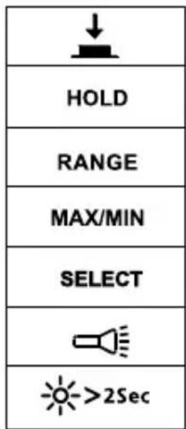
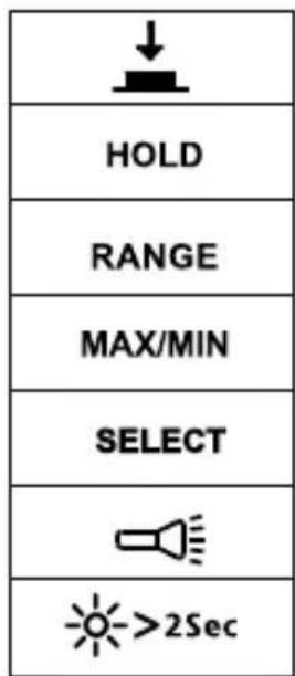
AM-550-EUR Function Buttons
| Button Measurement Function | |
| SELECT | Press the yellow SELECT button to select alternate measurement functions on the rotary switch. |
| RANGE / AUTO T1-T2 | Manual or auto range switching for voltage current, resistance and capacitance. The default setting is Auto ranging, press to switch to manual ranging. Press for 2 seconds to return to auto-ranging.T1 or T2 or T1-T2 function switching for temperature measurement. |
| REL / [IMAGE] | Relative mode △ Press >2 seconds to turn ON or turn OFF flash light. |
| MAX/MIN / PEAK(1ms) | Press to enter Maximum / minimum reading memory mode. Press again for maximum reading; press again for minimum reading. Press >2 seconds to exit maximum/minimum reading mode.Press >2 seconds to enter Peak MAX/ Peak MIN mode. Press again for Peak MAX reading; press again for Peak MIN reading. Press >2 seconds to exit Peak MAX/ Peak MIN reading mode. |
| HOLD / [IMAGE]>2Sec | Display freezes present reading / press >2 seconds to turn ON or turn OFF LCD backlight. |
| Low imp. 400kΩ | For voltage measurement functions only. Press and hold the button to change the input impedance of V and COM terminal to 400kΩ. Release 400kΩ button to return to normal input impedance of V and COM terminal (around 10MΩ). |


Dual Display
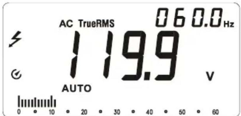
AC Voltage measurement
Primary display shows ac voltage.
Secondary display shows frequency.
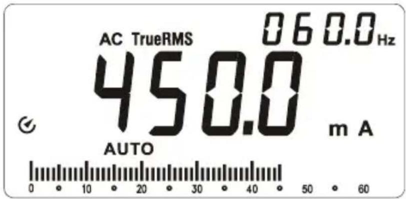
AC Current measurement
Primary display shows ac current.
Secondary display shows frequency.
Auto Power OFF
Auto power off: Approximately 15 minutes.
When the Meter is in auto power off mode, press any button to resume normal operation.
REL Measurement (V, A, Ω and +Measurement)
The Meter will calculate the values based on the stored value when set to related mode Display value under RELΔ Mode = Measured Value - Reference Value
Note: Entering relative mode is not allowed when the Meter displays "OL".
Incorrect Input Terminal Connection Warning
To alert you about the incorrect connection of input terminals, the Meter will display "Warning" and buzzer will sound when test leads are falsely inserted to terminals which are not for measurement of the selected functions.
| Function selected WARNING – Incorrect Terminal Connection | |
| V, Ω, +, -, +, Hz, %, △ | 10A, mA μA |
| mA μA°C °F | 10A |
| 10A | mA μA |
Hazardous Voltage Warning
LCD screen displays ♂ when the Meter detects a voltage ≥30 Vac or ≥42 V dc.
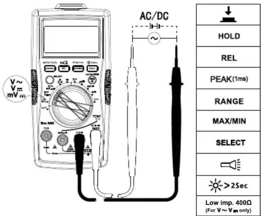
Measuring AC and DC Voltage
⚠️ To avoid personal injury or damage to the Meter, do not apply voltage higher than 1000V ac and 1000V dc. Buzzer will sound when detect a voltage higher than 1000V ac and 1000V dc.
Low Pass Filter
4
- To avoid personal injury or damage to the Meter, do not use low pass filter function to verify the presence of hazardous voltage in the circuit. Always use Voltage function to verify hazardous voltages.
- Do not apply voltage higher than 1000V.
Measuring AC voltage with Low Pass Filter:
Turn rotary switch to V\~ position and press SELECT button for Low Pass Filter mode, symbol is displayed on screen.
Making measurement under ac voltage mode by a low pass filter can block voltage above 1KHz. Low pass filter can be used to measure composite sine wave signal generated by inverter and variable frequency motor drives.

Note: The Meter goes into manual mode when Low Pass Filter mode is enabled. Auto-range mode is not available for Low Pass Filter option.
Measuring Frequency / Duty Cycle
⚠️ To avoid personal injury or damage to the Meter, do not apply voltage higher than 1000V.
- Frequency / Duty Cycle function
Step 1: Turn the rotary switch to Hz % position. Use SELECT button for Hz or duty cycle measurement.
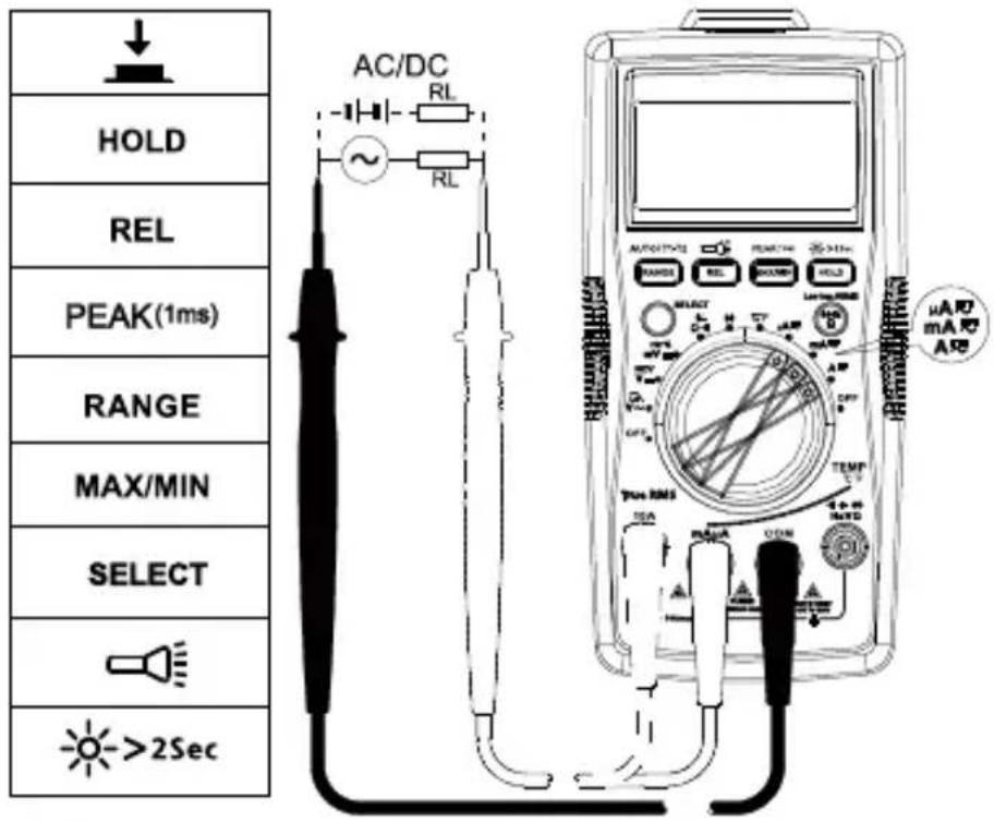
Step 2: Connect test leads to the circuit. Connecting diagram see below.
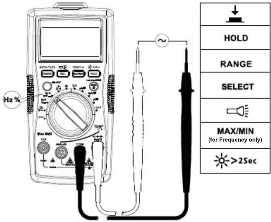
- Measuring Frequency by using ac Voltage function
Step 1: Turn the rotary switch to V\~ position.
Step 2: Connect test leads to the circuit. Connect the common (COM) test lead to the circuit before connecting the live lead (connecting diagram refer to "Measuring AC Voltage").
Primary display shows ac Voltage measurement reading. Secondary display shows Frequency measurement reading.
- Measuring Frequency by using ac current function
Step 1: Turn the rotary switch to A or mA or 10A position.
Step 2: Connect the test leads to the correct input 10A/mA μA current terminal and to the circuit before powering the circuit under test (connecting diagram refer to "Measuring AC Current").
Primary display shows ac current measurement reading. Secondary display shows Frequency measurement reading.
Measuring AC and DC Current
Press SELECT button to select ac or dc current measurement function.
To avoid personal injury or damage to the Meter:
-
Do not attempt to make an in-circuit current measurement when the open-circuit potential to earth ground exceeding 1000V
-
Switch to proper function and range for your measurement.
-
Do not place the test probe in parallel with a circuit when the test leads are connected to the current terminals.
-
Connect the test leads to the correct input 10A/mA μA current terminal and to the circuit before powering the circuit under test.
-
For current range from 8-10A, do not measure current for more than 20 minutes. Wait for 10 minutes before taking another measurement
-
After measurement, switch OFF the circuit's power before removing test leads from the circuit.
Measuring Resistance
⚠️ Disconnect circuit power and discharge all high-voltage capacitors before testing resistance.
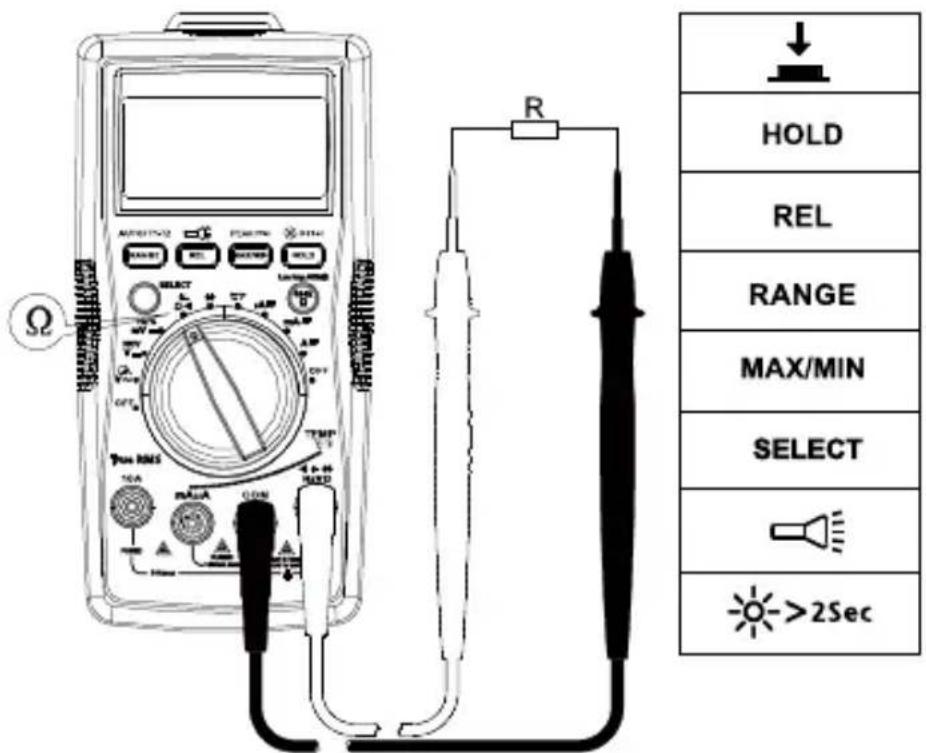
Note: On a higher resistance measurement (>1MΩ), the measurement may take a few seconds to get stable reading.
Over range or open circuit indication: OL
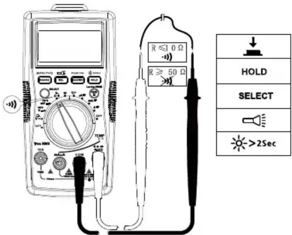
Measuring Continuity
⚠️ Disconnect circuit power and discharge all high-voltage capacitors before testing continuity.
Press SELECT button for continuity function.
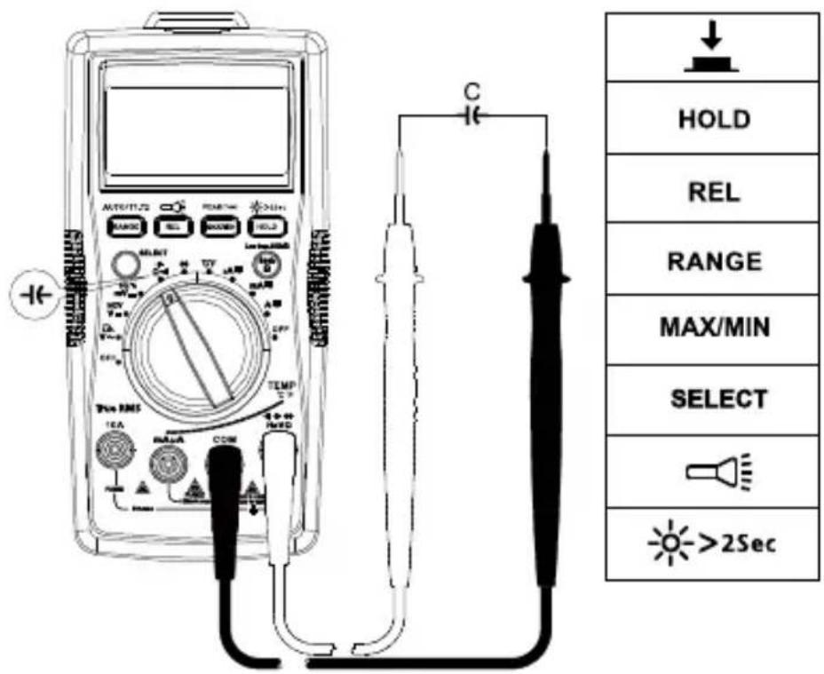
Measuring Capacitance
⚠️ Disconnect circuit power and discharge all high-voltage capacitors before measuring capacitance. Use dc Voltage function to check the capacitors are discharged.
Press SELECT button for capacitance measurement function.
Measuring Diode
⚠️ Disconnect circuit power and discharge all high-voltage capacitors before testing diode.
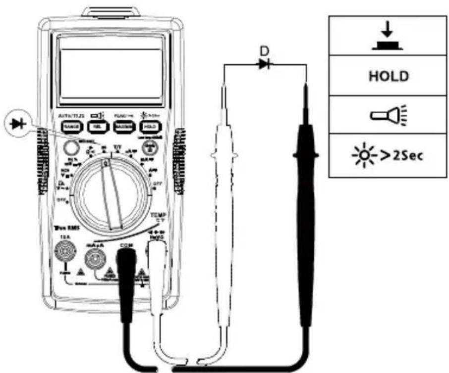
Note: A typical junction Voltage drops 0.5 V to 0.8 V.
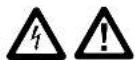
Measuring Temperature °C / °F
-
To avoid personal injury or damage to the Meter, do not apply the temperature probe to any live conductive parts.
-
Temperature sensor K-type (nickel-chromium/nichrosi) thermocouple is suitable for temperature measurement below 230^ C ( 446^ F).
Measurement steps:
Step 1: Turn the rotary switch to °C/°F position. The display will show "OPEN". Press SELECT button for conversion to °F measurement.
Step 2: Connect the temperature probe (K-type) to the Meter and to the surface to be measured. Two temperature surface points can be measured at the same time by using the provided temperature probes.
Step 3: Press RANGE button to select temperature measurement T2 or T1-T2 (the default temperature measurement is T1).
Non-Contact Voltage Detection (NCV Mode)
#
- To avoid personal injury or damage to the Meter, do not test on uninsulated high voltage wires.
- Buzzer will sound and screen will display "OL" when detecting ac Voltage above 90V ac.
- Do not test on hazardous live wires higher than 750V ac.
- Before and after hazardous voltage measurements, test the Meter by approaching to a known source such as a line ac Voltage or outlet to determine proper operation.
- At NCV mode, no test lead connections are required for NCV measurement.
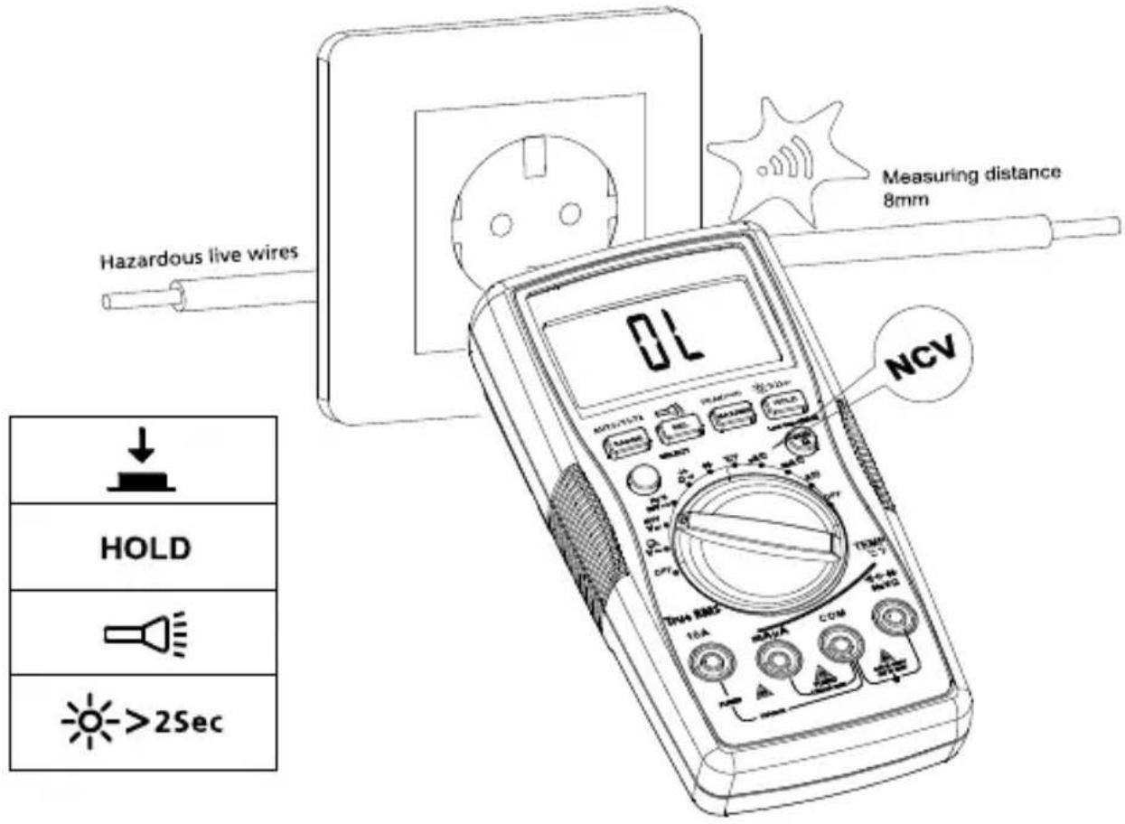
Buzzer will sound when the detected voltage is ≥90V , and the buzzer will be on. The distances between the wire and the meter should be ≤8mm .
Ambient temperature: 23°C ±5°C (73.4°F ±9°F); Relative temperature: ≤75%
Accuracy: ±(% of reading + digits)
Maximum voltage between input terminal and earth ground:
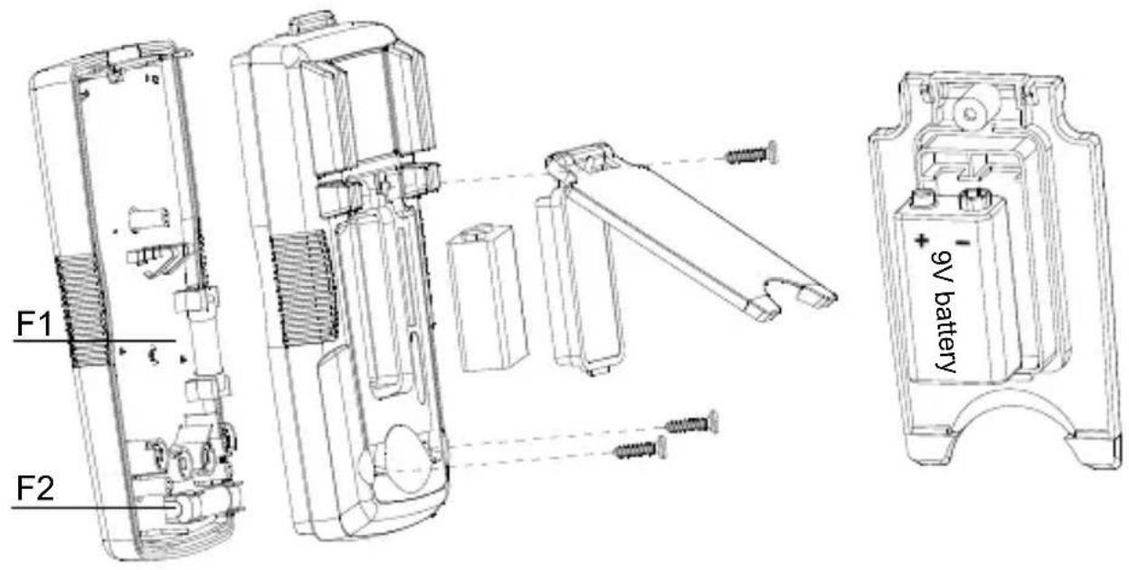
Fuse for mA μA input: F1 0.5A H 1000V fast-fuse, (Φ6.3×32)mm

Fuse for 10A input: F2 11A H 1000V fast-fuse, (Φ10×38)mm
Maximum display: Digital 5999 counts, updates 3/seconds.
Analog pointer display: 61 segments. Updates 20 times/seconds.
Over-range indication: OL
Range: Automatic and Manual
Altitude: Operating ≤ 2000m
Operating temperature: 0°C\~+40°C (32°F\~104°F)
Relative humidity: 0°C\~+30°C (32°F\~86°F) ≤75%; +30°C\~+40°C (86°F\~104°F) ≤50%
Storage temperature: -10°C\~+50°C (14°F\~122°F)
Electromagnetic compatibility: In an RF filed of 1V/m = Specified accuracy ± 5%
Battery: 9V, 6F22, NEDA1604 or equivalent
Low battery indication:
Dimensions (L x W x H): 182 mm x 90 mm x 45 mm (7.2 in x 3.5 in x 1.8 in)
Weight: Approximately 354g (0.78 lb) with batteries installed
- DC Voltage Measurement
| Range Resolution Best Accuracy | ||
| 600.0mV 0.1mV | ±(0.5%+3 LSD) | |
| 6.000V 1mV | ±(0.5%+2 LSD)60.00V 10mV | |
| 600.0V 100mV | ||
| 1000V 1V ±(1.0%+2 LSD) | ||
Input impedance: Around 10MΩ ;
Overload protection: ±1000V
2. AC Voltage Measurement
| Range Resolution | Accuracy | ||
| 45Hz – 400Hz(AM-540-EUR / AM-550-EUR) | 400Hz – 1kHz(AM-550-EUR) | ||
| 6.000V 1mV | ±(1.0%+3LSD) ±(2%+3 LSD) 60.00V 10mV | ||
| 600.0V 100mV | |||
| 1000V 1V | ±(1.2%+3LSD) | ±(2.5%+3 LSD) | |
Overload protection: 1000V rms
Input impedance: Around 10MΩ
Frequency response: 45Hz–400Hz (AM-540-EUR), 45Hz – 1kHz (AM-550-EUR)
AM-540-EUR: Average detecting, True-rms indication. rms indication.
AM-550-EUR: True-rms.
Note: Frequency (on secondary display) may not be displayed if the measured voltage is below 20% of the display voltage range.
3. Low Pass Filter
| Range Resolution Accuracy | ||
| 6.000V 0.001V | 45 to 200Hz ± (2%+40 LSD)200 to 440Hz ± (6%+40 LSD) | |
| 60.00V 0.01V | ||
| 600.0V 0.1V | ||
| 1000V | 1V | |
Block ac voltage signals above 1KHz
Overload protection: 1000Vp
4. Frequency Measurement
| Range Resolution Accuracy | ||
| 60.00Hz | 0.01 Hz | ±(0.1%+3 LSD) |
| 600.0Hz | 0.1 Hz | |
| 6.000kHz 1 Hz | ||
| 60.00kHz | 10 Hz | |
| 600.0 kHz | 100Hz | |
| 6.000MHz | 1KHz | ±(0.1%+3 LSD) |
| 60.00MHz | 10KHz | |
Overload protection: 1000Vp
5. Duty Cycle
| Range Resolution Accuracy | ||
| 10%~90% 0.01% | ±(1.2%+30 LSD) | |
Overload protection: 1000Vp
6. DC Current Measurement
| Range Resolution Accuracy | |||
| μA | 600.0μA 0.1 | μA | ±(1.0%+2LSD) |
| 6000μA 1μA | |||
| mA | 60.00mA 10 | μA | ±(1.2%+3 LSD) |
| 500.0mA 0.1 | mA | ||
| 10 A 1 | 0.00A 10mA ±(1.5%+3 LSD) | ||
Overload protection:
mA /μA range:F1 fuse, 0.5A H 1000V fast-fuse, (Φ6.3×32)mm
10 A range:F2 fuse, 11A H 1000V fast-fuse, (Φ10×38)mm
7. AC Current Measurement
| Range Resolution | Accuracy | ||
| 45Hz – 400Hz (AM-540-EUR / AM-550-EUR) | 400Hz – 1KHz (AM-550-EUR) | ||
| μA | 600.0μA 0.1 μA | ±(1.2%+5 LSD) ±(2%+5 LSD) | |
| 6000μA | 1μA | ||
| mA | 60.00mA 10 μA | ±(1.5%+5 LSD) ±(3%+5 LSD) | |
| 500.0mA | 0.1mA | ||
| 10 A | 10.00A | 10mA | ±(2%+5 LSD) ±(4%+5 LSD) |
Overload protection:
μA mA range: F1 0.5A H 1000V fast-fuse, (Φ6.3×32)mm
10 A range: F2 11A H 1000V fast-fuse, (Φ10×38)mm
Frequency response: 45Hz – 400Hz(AM-540-EUR), 45Hz – 1KHz (AM-550-EUR)
Note: Frequency (on secondary display) may not be displayed if the measured current is below 20% of the display current range.
8. Resistance Measurement
| Range Resolution Accuracy | ||
| 600.0Ω 0.1Ω | ±(1.2%+2 LSD) | |
| 6.000kΩ 1Ω | ±(1.0%+2 LSD)60.00kΩ 10Ω | |
| 600.0kΩ 100Ω | ||
| 6.000MΩ 1kΩ | ±(1.2%+2 LSD) | |
| 60.00MΩ 10kΩ | ±(1.5%+2 LSD) | |
Open circuit voltage: Around 0.5V
Overload protection: 1000Vp
9. ⋅): Continuity ➤: Diode Measurement
| Range | Resolution Accuracy | |
| 0.1Ω | Open circuit voltage is around -3V dc.Resistance >50Ω, buzzer will not sound.Resistance ≤10Ω, buzzer will sound. | |
| 1mV | Display range is 0V to 2.8V. Normal voltage is around 0.5V to 0.8V for silicon PN junction. | |
Overload protection: 1000Vp
10. Capacitance Measurement
| Range Resolution | Accuracy | |
| 60.00nF | 10pF | Under REL status: ±(3%+5 LSD) |
| 600.0nF 100pF | ±(3%+5 LSD) | |
| 6.000μF | 1nF | |
| 60.00μF | 10nF | |
| 600.0μF 100nF | ±(4%+5 LSD) | |
| 6000μF 1μF | ±(5%+5 LSD) | |
| 60mF | 10μF | Not specified |
Overload protection: 1000Vp
11. Temperature Measurement
| Range Resolution Accuracy | ||
| -40 – 40°C | +8 LSD) 1°C | ±(2%+8 LSD) |
| >40 – 400°C ±(1% | ||
| >400 – 1000°C ±2.5% | ||
| -40 – 104°F | +12 LSD) 2°F | ±(2%+12 LSD) |
| >104 – 752°F ±(1% | ||
| >752 – 1832°F ±2.5% | ||
Overload protection: 1000Vp
K-type (nickel-chromium/nichrosi) thermocouple must be used for temperature measurements.
MAINTENANCE AND REPAIR
If the Meter fails to operate, check battery, test leads, etc., and replace as necessary.
Double check the following:
- Replace the fuse or battery if the meter does not work.
- Review the operating instructions for possible mistakes in operating procedure.
Quick check on 0.5A FUSE:
Step 1: Turn the rotary switch to mA position.
Step 2: Use a multimeter with continuity function to verify the fuse continuity for the fuse of mA/ A terminal. Connect the test leads to mA/ A terminal and COM terminal.
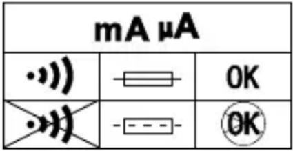 |
Continuity buzzer activates: the fuse is OK
Continuity buzzer is not activated: the fuse is burnt. Replace the fuse as specified.
F1 0.5A H 1000V fast-fuse, (6.3×32)mm
Quick check on 10A FUSE:
Step 1: Turn the rotary switch to A position.
Step 2: Use a multimeter with continuity function to verify the fuse continuity for the fuse of 10A terminal. Connect the test leads to 10A terminal and COM terminal.
| A | ||
| ·)) | - | OK |
| ·) | - | OK |
Continuity buzzer activates: the fuse is OK
Continuity buzzer is not activated: the fuse is burnt. Replace the fuse as specified.
F2 11A H 1000V fast-fuse, (Φ10×38)mm
Except for the replacement of the battery, repair of the meter should be performed only by an Authorized Service Center or by other qualified instrument service personnel.
The front panel and case can be cleaned with a mild solution of detergent and water. Apply sparingly with a soft cloth and allow to dry completely before using. Do not use aromatic hydrocarbons, gasoline or chlorinated solvents for cleaning.


WARNING
To avoid shock, injury, or damage to the Meter:
Disconnect test leads before opening case.
Use ONLY fuses with the amperage, interrupt, voltage, and speed ratings specified.
Replacing BATTERY follow below steps:
- Disconnect the test lead probe from measuring circuit.
- Turn the Meter to OFF position.
- Remove the screws from the battery cover and open the battery cover
- Remove the batteries and replace with one 9V (6F22) or equivalent. The battery cover provides the correct polarity fitting construction design. Install the battery in the battery cover.
- Put the battery cover back and re-fasten the screw.
Battery: 9V (6F22) Battery or equivalent
Replacing FUSE follow below steps:
- Disconnect the test lead probe from measuring circuit.
- Turn the Meter to OFF position.
- Remove the screws from the enclosure and open the enclosure.
- Remove the broken fuse and replace with new specified fuse.
- Put the enclosure back and re-fasten the screw.
Fuse ratings:
mA /μA input terminal: F1 fuse, 0.5A H 1000V fast-fuse, (Φ6.3×32)mm
10 A input terminal: F2 fuse, 11A H 1000V fast-fuse, (Φ10×38)mm
Mesure de capacité
Misure di capacità
45 Hz - 1 kHz (AM-550-EUR)
45 Hz - 1 kHz (AM-550-EUR)
| HOLD |
| REL |
| PEAK(1ms) |
| RANGE |
| MAX/MIN |
| SELECT |
| Low imp. 400Ω(For V~Vm only) |
Filtro de paso bajo
#

45 Hz - 1 kHz (AM-550-EUR)
45 Hz - 1 kHz (AM-550-EUR)
©2017 Amprobe Test Tools.
Meting capaciteit
AM-550-EUR: True-rms.
AM-540-EUR
AM-550-EUR
DCyfrowy multimetr
KONSERWACJA I NAPRAWA
AM-540-EUR AM-550-EUR Digital Multimeter
Användarhandbok
©2017 Amprobe Test Tools.
Med enerett. Trykt i Kina.
Begrenset garanti og ansvarsbegrensning
Amprobe-produktet skal være uten defekter i materiale og utførelse i ett år fra kjøpsdatoen med mindre lokale lover krever noe annet. Denne garantien dekker ikke sikringer, éngangsbatterier eller skader som skyldes uhell, vanskjøtsel, misbruk, endring, forurensning, eller unormale driftsforhold eller håndtering. Forhandlere har ikke rett til å forlenge garantier på vegne av Amprobe. For å få service i garantiperioden må du returnere produktet med kjøpsbevis til et autorisert Amprobe-servicesenter eller til en Amprobe-forhandler eller -distributør. Se avsnittet Reparasjon for mer informasjon. DENNE GARANTIEN ER DITT ENESTE BOTEMIDDEL. ALLE ANDRE GARANTIER – ENTEN DIREKTE, INDIREKTE ELLER LOVBESTEMTE – INKLUDERT UNDERFORSTÅTTE GARANTIER OM EGNETHET FOR ET SPESIELT FORMÅL ELLER SALGBARHET, FRASKRIVES HERVED. PRODUSENTEN SKAL IKKE VÆRE ANSVARLIG FOR SPESIELLE, INDIREKTE, TILFELDIGE SKADER ELLER F∅LGESKADER ELLER TAP, UANSETT ÅRSAK ELLER TEORI. Siden noen stater eller land ikke tillater fraskrivelse eller begrensning av en garanti eller av tilfeldige skader eller følgeskader, er det mulig at denne ansvarsbegrensningen ikke gjelder for deg.
Reparasjon
SPESIFIKASJONER....20
VEDLIKEHOLD....24
BYTTE BATTERI OG SIKRING....25
SYMBOLER
Målingskapasitans
VEDLIKEHOLD OG REPARASJON
AM-540-EUR
AM-550-EUR
©2017 Amprobe Test Tools.
Koko (P x L x S) 182mm x 90mm x 45mm
AM-540-EUR AM-550-EUR Multímetro digital
Manual do utilizador
10/2017, Rev.4
©2017 Amprobe Test Tools.
ESPECIFICAÇÕES......20
MANUTENÇÃO ....24
45 Hz - 1 kHz (AM-550-EUR)
AM-540-EUR AM-550-EUR Digital Multimeter
Brugervejledning
10/2017, Rev.4
©2017 Amprobe Test Tools.
Alle rettigheder forbeholdes. Trykt i Kina.
Low-pass filter....9
Måling af kapacitet
AM-550-EUR: Virkelig rms.
Visit beha-amprobe.com for
- Catalog
- Application notes
• Product specifications - User manuals
Beha-Amprobe®
beha-amprobe.com
c/o Fluke Europe BV
Science Park
Eindhoven 5110
NL-5692 EC Son
Tel.: +49 (0) 7684 8009 - 0

Please Recycle