MKX50135mmT2.9 - Lens FUJIFILM - Free user manual and instructions
Find the device manual for free MKX50135mmT2.9 FUJIFILM in PDF.

User questions about MKX50135mmT2.9 FUJIFILM
0 question about this device. Answer the ones you know or ask your own.
Ask a new question about this device
Download the instructions for your Lens in PDF format for free! Find your manual MKX50135mmT2.9 - FUJIFILM and take your electronic device back in hand. On this page are published all the documents necessary for the use of your device. MKX50135mmT2.9 by FUJIFILM.
USER MANUAL MKX50135mmT2.9 FUJIFILM
E MK18-55mmT2.9/MK50-135mmT2.9
X MKX18-55mmT2.9/MKX50-135mmT2.9
E MK18-55mmT2.9/MK50-135mmT2.9
X MKX18-55mmT2.9/MKX50-135mmT2.9
EMK18-55mmT2.9/MK50-135mmT2.9

text_image
FUJINON ① ② ③ ④ ⑤ ⑥ ⑦ ⑧ ⑨ ⑯ ⑮ ⑯ ⑰ ⑱ ⑲ ⑳ ⑪ ⑫ ⑬ ⑭ ⑮ ⑯XMKX18-55mmT2.9/MKX50-135mmT2.9
text_image
FUJINON 1 2 3 4 5 6 7 8 9 10 11 12 13 14 15 16 17 18 19natural_image
Technical line drawing of a long, multi-lens optical lens with a detached clip (no text or symbols)text_image
Technical diagram of a mechanical device with numbered components for identificationtext_image
Technical diagram of a camera assembly with numbered components for identificationX 三脚座の取り付け
text_image
Technical diagram showing a camera lens assembly with labeled parts and directional arrows indicating motion or adjustment.text_image
Diagram of a camera lens with numbered parts and directional arrows indicating motion or adjustment.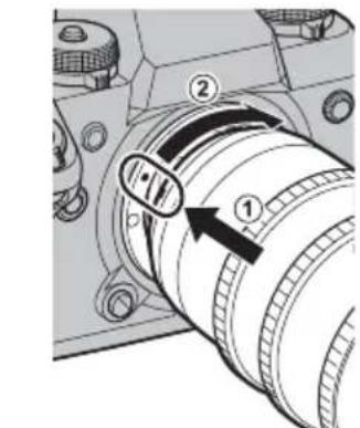
text_image
Technical diagram of a mechanical component with numbered parts and directional arrows indicating motion or movement.natural_image
Technical line drawing of a camera lens assembly with no visible text or symbolsレンズフード取り付けつまみ
■取り付け
natural_image
Simple line drawing of a circular object inside a rounded rectangle (no text or symbols)E MK18-55mm
X MKX18-55mm
natural_image
Simple geometric diagram with concentric rectangles and a central circle (no text or symbols)EMK50-135mm
X MKX50-135mm
操作方法
text_image
Technical diagram of a mechanical device with numbered components and directional arrows indicating motion or flow.X
text_image
Technical diagram of a camera lens with numbered parts and directional arrows indicating motion or assembly.E
text_image
Diagram of a camera lens assembly with numbered parts and directional arrows indicating motion or adjustment.X
text_image
Diagram of a camera lens with labeled parts and directional arrows indicating adjustment or insertion stepsフランジバックの調整
E http://www.fujifilm.com/support/optical_devices/tv_cine/resources/
X http://www.fujifilm.com/support/digital_cameras/compatibility/index.html
アフターサービスについて
http://www.fujifilm.com/support/optical_devices/tv_cine/pdf/index/Tv_Cine_Lenses_Contact_Us.pdf
http://www.fujifilm.com/contact/
Introduction
Thank you for your purchase of this product. Be sure that you have read this manual and understood its contents before using the camera. Keep the manual where it will be read by all who use the product.
About This Manual
This manual includes instructions for the following FUJINON cinema lenses: the E-mount MK18-55mm T2.9/MK50-135mmT2.9 and the X-mount MKX18-55mmT2.9/MKX50-135mmT2.9.
Symbols
This icon marks information that should be read to prevent damage to the product.
This icon marks additional information that may be helpful when using the product.
E This icon marks instructions for E-mount MK18-55mmT2.9/MK50-135mmT2.9 lenses.
X This icon marks instructions for X-mount MKX18-55mmT2.9/MKX50-135mmT2.9 lenses.
Instructions not marked with either of the above icons apply to both E- and X-mount lenses.
For Your Safety
Be sure to read these notes before use
Safety Notes
Thank you for your purchase of this product. For repair, inspection, and internal testing, contact your Fujifi Im dealer.
- Make sure that you use the lens correctly. Read these safety notes and the camera Owner's Manual carefully before use.
• After reading these safety notes, store them in a safe place.
About the Icons
The icons shown below are used in this document to indicate the severity of the injury or data can result if the information indicated by the icon is ignored and the product is used incorrectly as a result.
| WARNING | This icon indicates that death or serious injury can result if the information is ignored. | |
| CAUTION | This icon indicates that personal injury or material damage can result if the information is ignored. |
The icons shown below are used to indicate the nature of the instructions which are to be observed.
| Triangular icons tell you that this information requires attention ("Important"). | |
| Circular icons with a diagonal bar tell you that the action indicated is prohibited ("Prohibited"). | |
| Filled circles with an exclamation mark indicate an action that must ("Required"). |
The symbols on the product (including the accessories) represent the following:
| ~ | AC |
| = | DC |
| Class II equipment (The construction of the product is double-insulated.) |
E MK18-55mmT2.9 / MK50-135mmT2.9
| WARNING | |
| Do not touch the threads on the front or rear of the product. Failure to observe this precaution could result in injury. | |
| Should the product be damaged in a fall or other accident, do not touch the broken parts. Failure to observe this precaution could result in injury. | |
| Do not place on unstable surfaces. The product may fall, causing injury. | |
| Do not view the sun through the lens or camera viewfnders. Failure to observe this precaution can cause permanent visual impairment. | |
| CAUTION | |
| Do not leave in locations subject to very high temperatures. Do not leave the product in a closed vehicle or direct sunlight. Failure to observe this precaution can cause fi re or burns. | |
| Keep out of the reach of small children. This product could cause injury in the hands of a child. | |
| Keep the sun out of the frame when shooting backlit subjects. Sunlight focused into the camera when the sun is in or close to the frame can cause fi re or burns. | |
| When the product is not in use, replace the lens caps and store out of direct sunlight. Sunlight focused by the lens can cause fi re or burns. | |
| Do not carry the camera or lens while they are attached to a tripod. The product can fall or strike other objects, causing injury. | |
MX18-55mmT2.9 / MKX50-135mmT2.9
| WARNING | |
| Do not use in the bathroom or shower | Do not immerse in or expose to water, to observe this precaution can cause a fire or electric shock. |
| Do not disassemble | Do not disassemble (do not open the case).Failure to observe this precaution can cause fire, electric shock, or injury due to product malfunction. |
| Do not touch internal parts | Should the case break open as the result of a fall or other accident, do not touch the exposed parts.Failure to observe this precaution could result in electric shock or in injury from touching the damaged parts. Remove the camera battery immediately, taking care to avoid injury or electric shock, and take the product to the point of purchase for consultation. |
| Do not place on unstable surfaces. The product may fall, causing injury. | |
| Do not view the sun through the lens or camera view fi nders. Failure to observe this precaution can cause permanent visual impairment. | |
| CAUTION | |
| Do not use or store in locations that are exposed to steam, or smoke or are very humid or extremely dusty. Failure to observe this precaution can cause fire or electric shock. | |
| Do not leave in direct sunlight or in locations subject to very high temperatures, such as in a closed vehicle on a sunny day. Failure to observe this precaution can cause fire. | |
| Keep out of the reach of small children. This product could cause injury in the hands of a child. | |
| Do not handle with wet hands. Failure to observe this precaution can cause electric shock. | |
| Keep the sun out of the frame when shooting backlit subjects. Sunlight focused into the camera when the sun is in or close to the frame can cause fire or burns. | |
| When the product is not in use, replace the lens caps and store out of direct sunlight. Sunlight focused by the lens can cause fire or burns. | |
| Do not carry the camera or lens while they are attached to a tripod. The product can fall or strike other objects, causing injury. | |
Failure
For Customers in the U.S.A.
Tested To Comply With FCC Standards
FOR HOME OR OFFICE USE

FCC Statement: This device complies with P the FCC Rules. Operation is subject to the following two conditions: (1) This device may not cause harmful interference, and (2) this device must accept any interference received, including interference that may cause undesired operation.
CAUTION: This equipment has been tested and found to comply with the limits for a Class B digital device, pursuant to Part 15 of the FCC Rules. These limits designed to provide reasonable protection against harmful interference in a residential installation. This equipment generates, uses, and can radiate radio frequency energy and, if not installed and used in accordance with the instructions, may cause harmful interference to radio communications. However, there is no guarantee that interference will not occur in a particular installation. If this equipment does cause harmful interference to radio or television reception, which can be determined by turning the equipment off and on, the user is encouraged to try to correct the interference by one or more of the following measures: • Reorient or relocate the receiving antenna.
- Increase the separation between the equipment and receiver.
- Connect the equipment into an outlet on a circuit different from that to which the receiver is connected.
- Consult the dealer or an experienced radio/TV technician for help.
- You are cautioned that any changes or modifications not expressly approved in this manual could void the user's authority to operate the equipment.
Notes on the Grant: To comply with Part 15 of the FCC Rules, this product must be used with a Fujifi Im-specific ed ferrite-core A/V cable, USB cable, and DC supply cord.
For Customers in Canada
CAN ICES-3 (B)/NMB-3(B)
CAUTION: This Class B digital apparatus complies with Canadian ICES-003.
IMPORTANT SAFETY INSTRUCTIONS
- Read these instructions.
- Keep these instructions.
- Heed all warnings.
- Follow all instructions.
-
Do not use this apparatus near water (excluding waterproof products).
-
Clean only with a dry cloth.
- Do not block any ventilation openings. Install in accordance with the manufacturer's instructions.
- Do not install near any heat sources such as radiators, heat registers, stoves, or other apparatus (including amplifiers) that produce heat.
- Protect the power cord from being walked on or pinched particularly at plugs, convenience receptacles, and the point where they exit from the apparatus.
- Only use attachments/accessories specified by the manufacturer.
- Unplug this apparatus during lightning storms or when unused for long periods of time.
- Refer all servicing to qualified service personal. Servicing is required when the apparatus has been damaged in any way, such as power supply cord or is damaged, liquid has been spilled or objects have fallen into the apparatus, the apparatus has been exposed to rain or moisture, does not operate normally, or has been dropped.
Disposal of Electrical and Electronic Equipment in Private Households
In the European Union, Norway, Iceland and Liechtenstein: This symbol on the product, or in the manual and in the warranty, and/or on its packaging indicates that this product shall not be treated as household waste. Instead it should be taken to an applicable collection point for the recycling of electrical and electronic equipment.
By ensuring this product is disposed of correctly, you will help prevent potential negative consequences to the environment and human health, which could otherwise be caused by inappropriate waste handling of this product.
The recycling of materials will help to conserve natural resources. For more detailed information about recycling this product, please contact your local city office, your household waste disposal service or the shop where you purchased the product.
In Countries Outside the European Union, Norway, Iceland and Liechtenstein: If you wish to discard this product, including the batteries or accumulators, please contact your local authorities and ask for the correct way of disposal.
Australian RCM

Product Care
- When using a lens hood, do not pick up or hold the camera using only the hood.
- Use a blower to remove dust and lint from the glass surfaces of the lens or filter. To remove smudges and fingerprints, apply a small amount of lens cleaner to a soft, clean cotton cloth or lens-cleaning tissue and clean from the center outwards using a circular motion, taking care not to leave smears or touch the glass with your fingers.
- Never use organic solvents such as paint thinner or benzene to clean the lens.
- Attach the front and rear caps when the lens is not in use.
- Store the lens and filter in cool, dry locations to prevent mold and rust. Do not store in direct sunlight or with naphtha or camphor moth balls.
- Keep the lens dry. Rusting can cause irreparable damage. Wipe off rain and water droplets.
- Leaving the lens near a heater or in other extremely hot locations could cause damage or warping.
- There may be a case that the glasses of the lens mist when the lens is carried from a cool place to a place of high temperature and high humidity. To avoid a mist on the glasses, before moving the lens, let the lens adjust to the ambient temperature of the place where the lens will be used.
- Keep the lens signal contacts clean (☒ lenses only).
Lens Features
These lenses are for movies.
E MK18-55mmT2.9/MK50-135mmT2.9
These fully manual lenses E-mounts have no electronic contacts. There is no exchange between the camera and lens.
X MKX18-55mmT2.9/MKX50-135mmT2.9
These fully manual lenses X-mounts are equipped with electronic contacts. Data can be exchanged between the camera and lens.
The lens may not perform as expected and some features may not be available with older versions of the camera firmware. Be sure to update the camera firmware to the latest version. Instru viewing the camera firmware version and updating camera firmware are available from the following website:
http://www.fujifilm.com/support/digital_cameras/software/#firmware
If you do not have access to a computer, support is available from the local distributor listed in the "FUJIFILM Worldwide Network" material provided with your camera.
Supplied Accessories
E MK18-55mmT2.9/MK50-135mmT2.9
- Front lens cap (Part No. BU00006892-1**)
- Rear lens cap (Part No. BB00038220-1**)
- Lens hood (MK18-55mm: Part No. BU00007497-1**/MK50-135mm: Part No. BU00007584-1**)
- Lens hood cap (Part No. 057B00742627*)
- Wrapping cloth (Part No. FZ00010454-1**)
- Zoom lever (Part No. 047B00160740*)
- Support foot ×1 (25.5 mm/M3, for support rod attachment, Part No. BB00038388-1**)
- Extension foot ×2 (17.95 mm, for support rod attachment, Part No. BB00035717-1**)
X MKX18-55mmT2.9/MKX50-135mmT2.9
- Front lens cap (Part No. BU00006892-1**)
- Rear lens cap (Part No. BB00036846-1**)
- Lens hood (MKX18-55mm: Part No. BU00007497-1**/MKX50-135mm: Part No. BU00007584-1**)
- Lens hood cap (Part No. 057B00742627*)
- Wrapping cloth (Part No. FZ00010454-1**)
- Zoom lever (Part No. 047B00160740*)
- Support foot ×1 (18 mm/M5, for support rod attachment, Part No. BB00041810-10*)
- Tripod collar foot (Part No. BF00019594-1**)
The part numbers in parentheses are required when ordering spares or replacements.
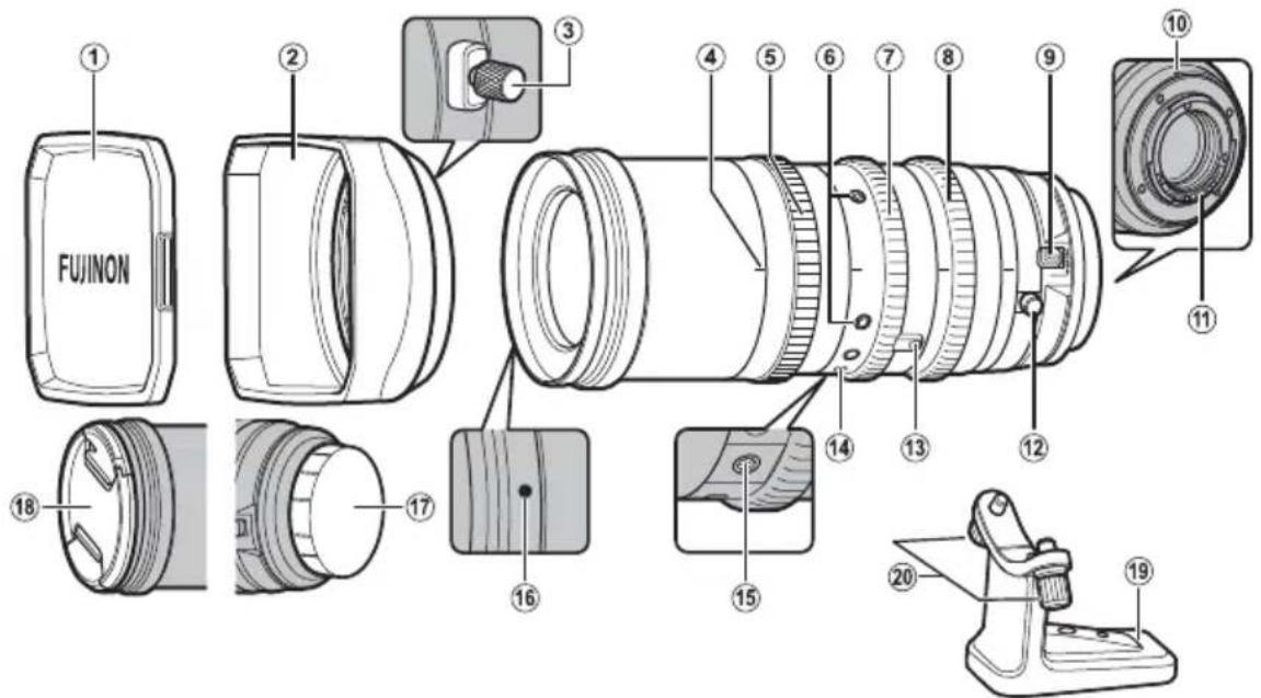
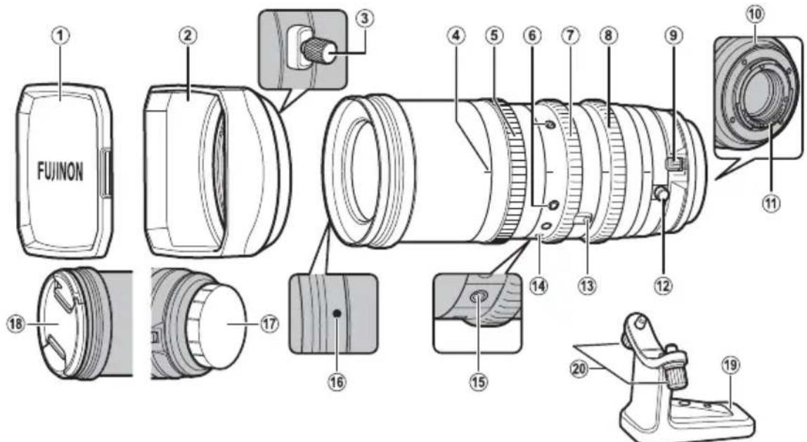
Parts of the Lens
E MK18-55mmT2.9/MK50-135mmT2.9

text_image
FUJINON ① ② ③ ④ ⑤ ⑥ ⑦ ⑧ ⑨ ⑯ ⑮ ⑯ ⑰ ⑱ ⑲ ⑳ ⑪ ⑫ ⑬ ⑭ ⑮ ⑯X MKX18-55mmT2.9/MKX50-135mmT2.9
text_image
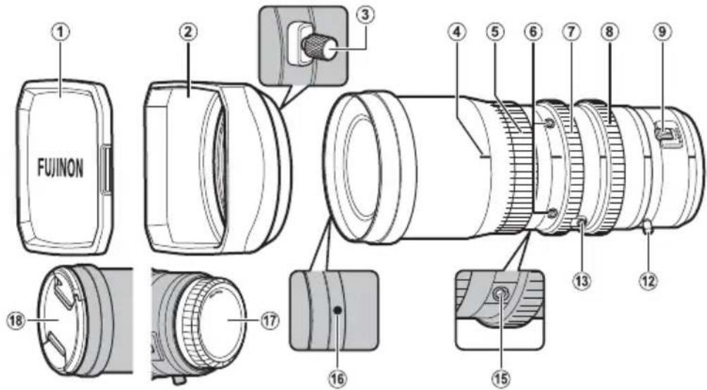
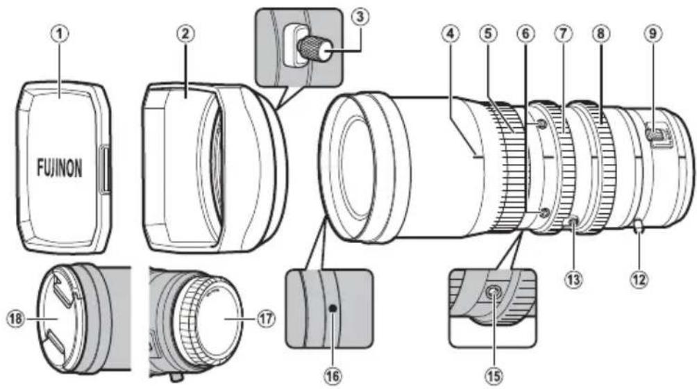
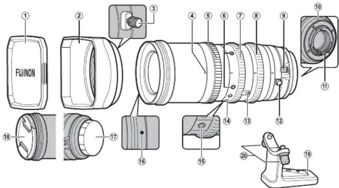
FUJINON ① ② ③ ④ ⑤ ⑥ ⑦ ⑧ ⑨ ⑩ ⑪ ⑫ ⑬ ⑭ ⑮ ⑯ ⑰ ⑱ ⑲ ⑳ ㉑ ㉒ ㉓ ㉔ ㉕ ㉖ ㉗ ㉘ ㉙ ㉚ ㉛ ㉜ ㉝ ㉞ ㉟ ㉳① Lens hood cap
② Lens hood ( EN-7)
③ Hood lock knob
④ Lens index
⑤ Focus ring
⑥ Service tap sockets ×4 (M3, depth 3 mm)
⑦ Zoom ring
⑧ Aperture ring
⑨ Macro ring with macro switch
⑩ Mounting mark *
* X only.
⑪ Lens signal contacts *
⑫ F.f (fl ange focus) ring with F.f lock knob
⑬ Zoom lever socket ×1 (M3, depth 2.8 mm)
⑭ Tripod foot mounting position index *
⑮ Support foot socket
⑯ Hood mounting mark
⑰ Rear lens cap
⑱ Front lens cap
⑲ Tripod collar foot *
⑳ Tripod foot mounting screw *
Attaching Accessories
E X Attaching the Zoom Lever
The zoom lever attaches to the zoom lever socket. Screw the lever securely into the socket.
E Attaching Support and Extension Feet
The support foot is used when attaching the lens to a support rod (available separately from third-party suppliers). The support foot attaches to the support foot socket.
Example
① Lens
② Camera
③ Support rod
④ Support/extension foot
Use extension feet if the support foot is not long enough.
X Attaching the Support Foot
The support foot is used when attaching the lens to a support rod (available separately from third-party suppliers). The support foot attaches to the support foot socket.
Example
① Lens
② Camera
③ Support rod
④ Support foot
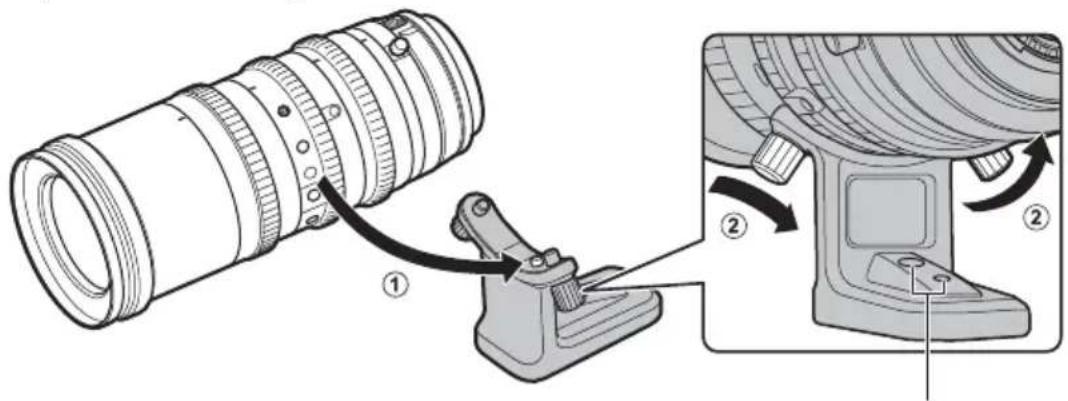
Attaching the Tripod Collar Foot
Align the pin on the tripod collar foot with the tripod foot mounting position index on the lens and tighten the tripod foot mounting screws.
text_image
Technical diagram showing a camera lens assembly with labeled parts and directional arrows indicating motion or adjustment.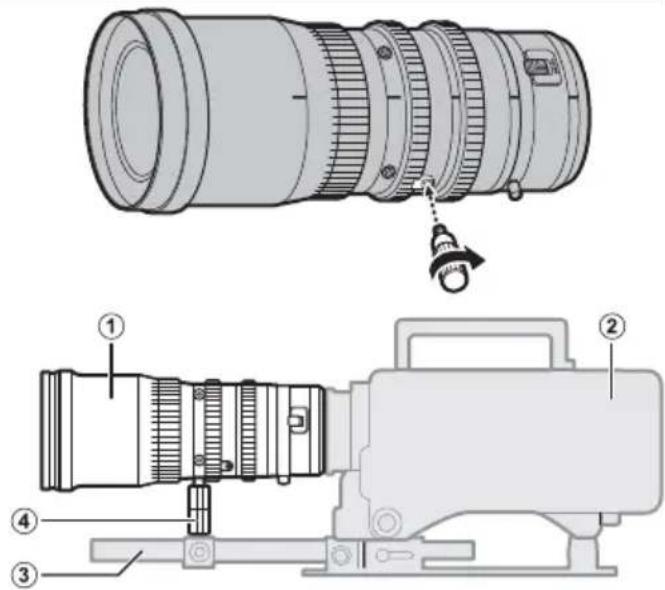
text_image
Technical diagram of a camera lens assembly with numbered parts and labeled parts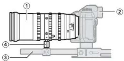
text_image
Technical diagram of a camera module with numbered components for identificationWhen attaching the tripod collar foot to a tripod, use these marks as a guide to the location of the tripod attachment screws.
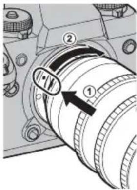
Attaching the Lens to the Camera
Example
text_image
Diagram of a camera lens with numbered parts and directional arrows indicating motion or adjustment.X Example

text_image
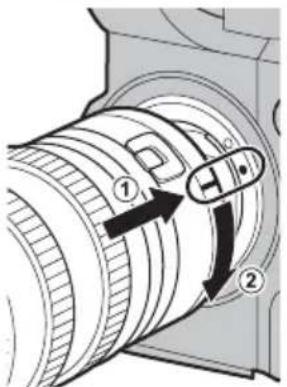
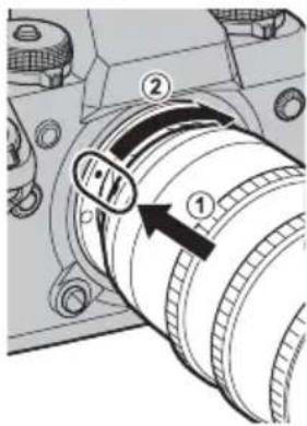
Technical diagram of a mechanical component with numbered parts and directional arrows indicating motion or movement.1 Remove the body cap from the camera and the rear cap from the lens.
2 Place the lens on the mount, keeping the lens index (E) or mounting mark (X) aligned with the mounting mark on the camera body.
① Note that in some cases there may not be a mounting mark on the camera body (E only).
- When attaching lenses, ensure that dust or other foreign matter does not enter the camera.
- Be careful not to touch the camera's internal parts.
- Rotate the lens until it clicks into place.
- Do not press the lens release button while attaching the lens.
Before using the lens for the first time or after attaching it to a different camera, measure the flange-back distance (EN-9).
The procedure for attaching the lens may differ depending on the camera.
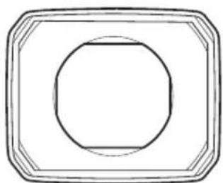
The Lens Hood
E X Example
text_image
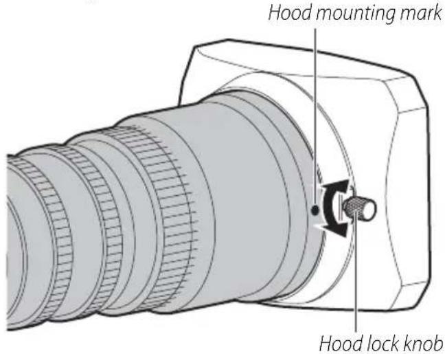
Hood mounting mark Hood lock knob■ Attaching the Hood
- Loosen the hood lock knob by rotating it cou clockwise.
- Slide the hood onto the lens until it contacts the raised ridge.
- Rotate the hood to align the lock knob with the hood mounting mark on the lens.
- Tighten the lock knob.
■ Removing the Hood
- Loosen the hood lock knob by rotating it cou clockwise.
- Slide the hood straight forward off the lens.
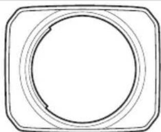
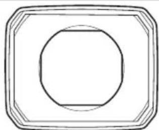
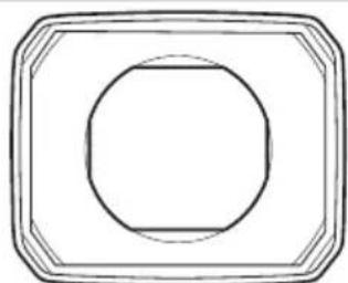
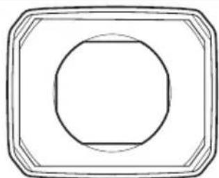
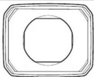
Hoods for different lenses have different shapes. Be sure to use the correct hood.
Use the lens hood cap with the lens hood.
Using the wrong hood may cause vignetting or other undesired results.
natural_image
Simple line drawing of a circular object inside a rounded square frame (no text or symbols)EMK18-55mm
X MKX18-55mm
natural_image
Simple geometric diagram with a circle inside a rounded rectangle (no text or symbols)EMK50-135mm
X MKX50-135mm
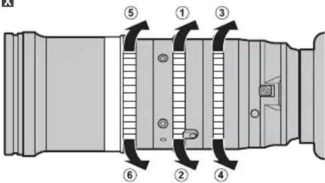
Lens Controls
! Be sure to remove any water before use to prevent it entering the lens.
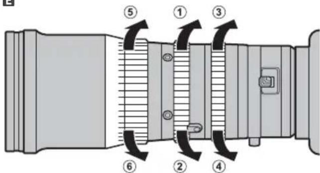
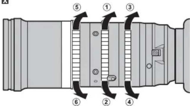
EX Zoom
Rotate the zoom ring to zoom out (①), increasing the area visible in the frame, or zoom in (②) on your subject so that it fills a larger area of the frame.
EX Aperture
Rotate the aperture ring to stop aperture down (③), raising the f-number and narrowing the aperture, or stop aperture up (④) to lower the f-number and widen the aperture.
EX Focus
Rotate the focus ring to adjust focus. Rotate the ring to reduce (⑤) or increase (⑥) the focus distance.
E
text_image
Technical diagram of a mechanical device with numbered components and directional arrows indicating motion or flow.X
text_image
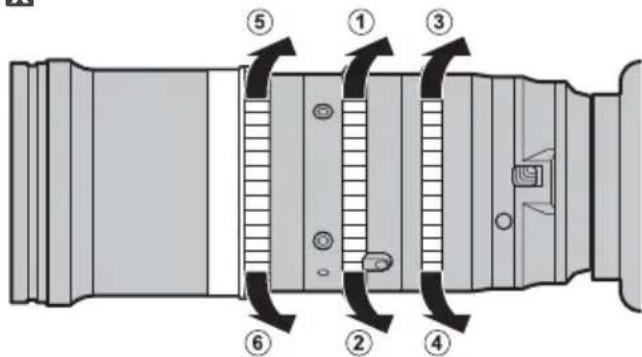
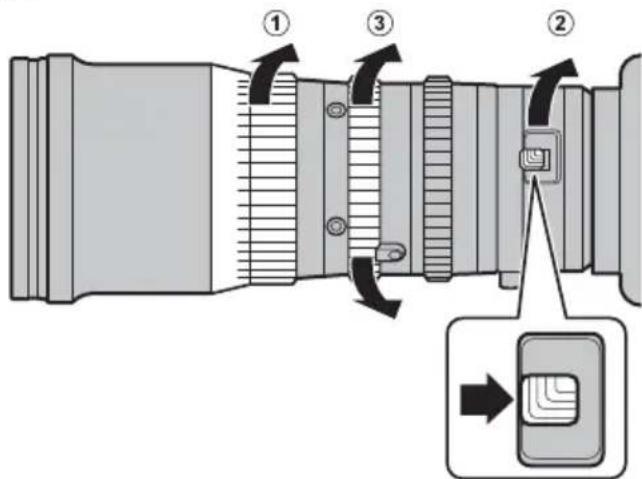
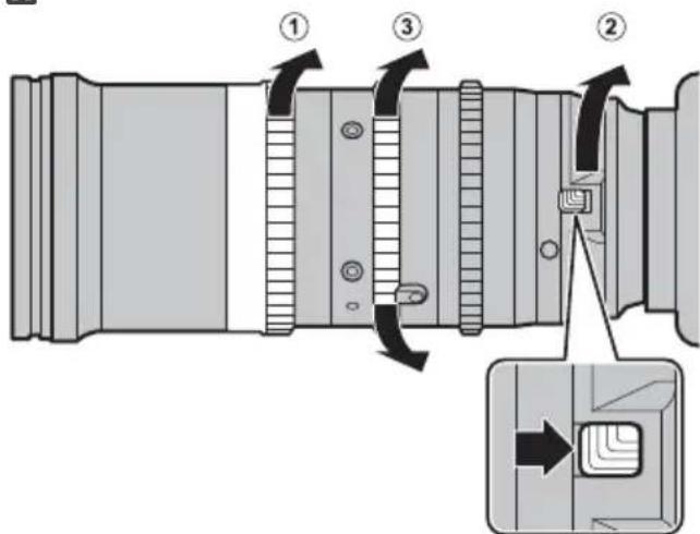
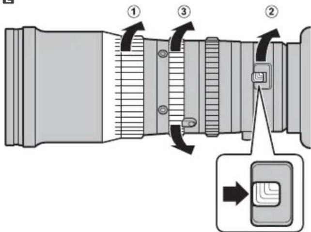
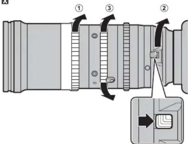
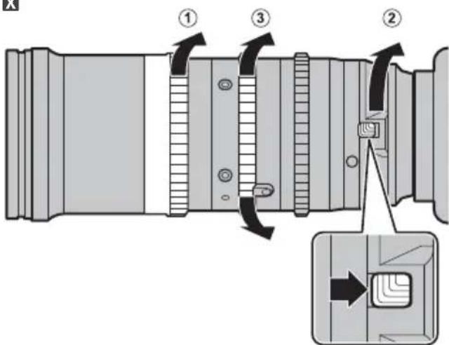
Technical diagram of a camera lens assembly with numbered parts and directional arrows indicating motion or assembly.EX Macro Zoom
① Rotate the focus ring to the minimum focus distance.
② Slide the macro switch as shown and keep it in this position while rotating the macro ring as far as it will go in the direction shown.
③ Rotate the zoom ring to choose a focus position.
Note: The lens can be used with the macro ring positioned between the macro and normal positions, but in this case the minimum focus distance and the focus range will be also be between those of the macro and normal positions.
Ending macro zoom: Rotate the macro ring in the direction opposite to that shown until the macro switch clicks back into place.
E
text_image
Diagram of a camera lens with numbered parts and directional arrows indicating motion or assembly stepsX
text_image
Technical diagram of a camera lens with numbered components and directional arrows indicating assembly stepsAdjusting the Flange Back Distance
The flange back distance is the distance between the lens mounting flange and the focal plane. It can vary depending on the camera and even such factors as the ambient temperature. If the flange back distance is incorrect, the camera will not focus at the correct distance when you zoom in or out. To correct the flange back distance, follow the steps below.
E X Preparation
1 Ready your subject. You can use a "Siemens star", a pattern of black-and-white radiating spokes available at http://www.fujifilm.com/support/optical_devices/tv_cine/resources/. If you are unable to access the Internet, you can use a high-contrast subject such as a black-and-white calendar.
2 Attach the lens to the camera and select maximum aperture.
Selecting maximum aperture reduces depth of field, making it easier to adjust focus. You will need to focus as accurately as possible when adjusting the fl ange back distance.
E X Performing the Adjustment
1 Loosen the F.f lock knob by rotating it counterclockwise.
2 Zoom all the way out.
3 Using the F.f lock knob, rotate the F.f ring to focus on the Siemens star. Find the position at which the black-and-white spokes are sharpest.
4 Zoom all the way in.
5 Focus on the Siemens star.
6 Zoom all the way out and see if the focus position is the same as it was in Step 3.
7 Repeat Steps 2-6 two or three times. The adjustment is complete when the optimal focus position is the same at all focal lengths. If it is not, further adjustment is required and you will need to return to Step 2.
8 Tighten the F.f lock knob securely when the adjustment is complete.
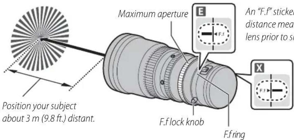
text_image
Position your subject about 3 m (9.8 ft.) distant. Maximum aperture An "F.f" sticker distance meas lens prior to sh F.f lock knob F.f ringAn "F.f" sticker showing the reference fl ange back distance measured at the factory is placed on the lens prior to shipment.
In dark locations, increase the camera's ISO sensitivity before performing the adjustment.
Third-Party Accessories
Up-to-date information on compatible third-party accessories is available at the following websites:
E http://www.fujifilm.com/support/optical_devices/tv_cine/resources/
X http://www.fujifilm.com/support/digital_cameras/compatibility/index.html
Repairs and Servicing
E Purchasers of the MK18-55mmT2.9/MK50-135mmT2.9 are referred to the following URL:
http://www.fujifilm.com/support/optical_devices/tv_cine/pdf/index/Tv_Cine_Lenses_Contact_Us.pdf
X Purchasers of the MKX18-55mmT2.9/MKX50-135mmT2.9 are referred to the information sheet included with the product or to the following URL:
http://www.fujifilm.com/contact/
Introduction
X MKX18-55mmT2.9 / MKX50-135mmT2.9

AVERTISSEMENT

E MK18-55mmT2.9/MK50-135mmT2.9
X MKX18-55mmT2.9/MKX50-135mmT2.9
http://www.fujifilm.com/support/digital_cameras/software/#firmware
E MK18-55mmT2.9/MK50-135mmT2.9
X MKX18-55mmT2.9/MKX50-135mmT2.9
E MK18-55mmT2.9/MK50-135mmT2.9
text_image
FUJINON ① ② ③ ④ ⑤ ⑥ ⑦ ⑧ ⑨ ⑯ ⑭ ⑮ ⑯ ⑰ ⑱ ⑲ ⑳ ⑪ ⑫ ⑬ ⑭ ⑮ ⑯X MKX18-55mmT2.9/MKX50-135mmT2.9

text_image
FUJINON ① ② ③ ④ ⑤ ⑥ ⑦ ⑧ ⑨ ⑩ ⑪ ⑯ ⑮ ⑰ ⑱ ⑲ ⑳ ⑰ ⑱ ⑲ ⑳ ⑰ ⑱ ⑲ ⑳ ⑰ ⑱ ⑲text_image
Technical diagram of a mechanical device with numbered components for identificationExemple
text_image
S ① ② ③ ④Exemple
text_image
Technical diagram showing a camera lens assembly with labeled parts and directional arrows indicating motion or adjustment.text_image
Diagram of a camera lens with numbered parts and directional arrows indicating motion or adjustment.X Exemple
text_image
Technical diagram of a mechanical component with numbered parts and directional arrows indicating motion or movement.natural_image
Technical line drawing of a camera lens assembly (no text or symbols)natural_image
Simple line drawing of a circular object inside a rounded square frame (no text or symbols)EMK18-55mm
X MKX18-55mm
natural_image
Simple geometric diagram with concentric rectangles and a central circle (no text or symbols)EMK50-135mm
X MKX50-135mm
text_image
E ⑤ ① ③ ⑥ ② ④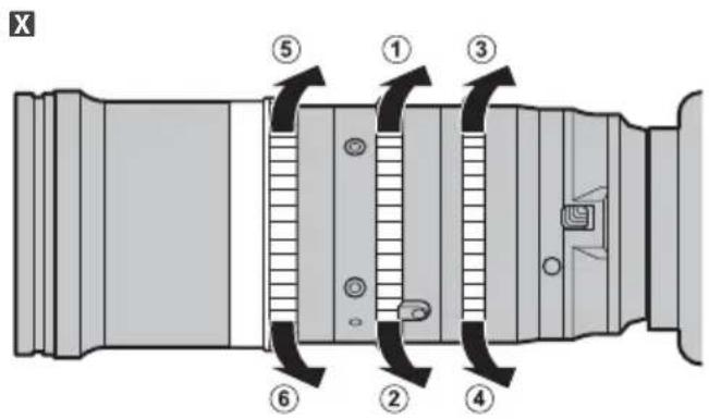
text_image
X ⑤ ① ③ ⑥ ② ④E X Zoom macro
text_image
a bague ① ③ ② male eront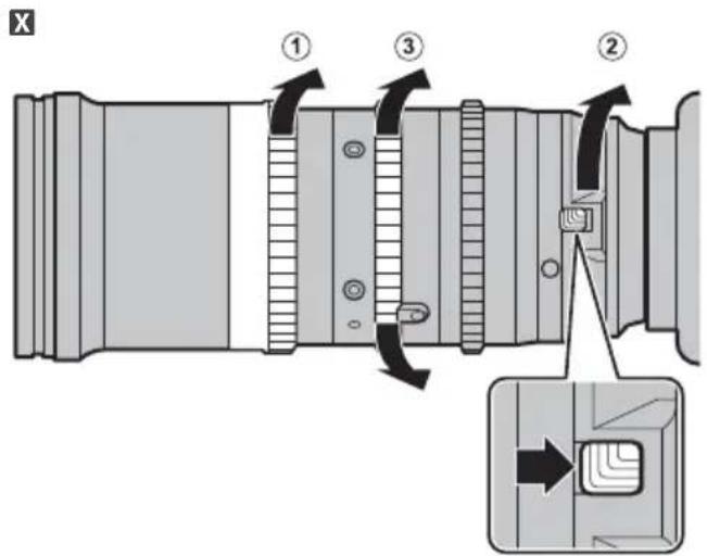
text_image
Technical diagram of a camera lens assembly with numbered parts and directional arrows indicating assembly stepsE http://www.fujifilm.com/support/optical_devices/tv_cine/resources/
X http://www.fujifilm.com/support/digital_cameras/compatibility/index.html
E MK18-55mmT2.9/MK50-135mmT2.9
X MKX18-55mmT2.9/MKX50-135mmT2.9
http://www.fujifilm.com/support/digital_cameras/software/#firmware
E MK18-55mmT2.9/MK50-135mmT2.9
X MKX18-55mmT2.9/MKX50-135mmT2.9
E MK18-55mmT2.9/MK50-135mmT2.9

text_image
FUJINON ① ② ③ ④ ⑤ ⑥ ⑦ ⑧ ⑨ ⑯ ⑮ ⑯ ⑰ ⑱ ⑲ ⑳ ⑪ ⑫ ⑬ ⑭ ⑮ ⑯X MKX18-55mmT2.9/MKX50-135mmT2.9

text_image
FUJINON 1 2 3 4 5 6 7 8 9 10 11 12 13 14 15 16 17 18 19natural_image
Technical line drawing of a long, multi-lens optical lens with a detached clip (no text or symbols)text_image
an ① ② ④ ③Beispiel
text_image
an ① ② ④ ③Beispiel
text_image
Technical diagram showing a camera lens assembly with labeled parts and directional arrows indicating motion or adjustment.text_image
Diagram of a camera lens with numbered parts and directional arrows indicating motion or adjustment.X Beispiel
text_image
Technical diagram of a mechanical component with numbered parts and directional arrows indicating motion or movement.natural_image
Simple line drawing of a circular object inside a rounded square frame (no text or symbols)EMK18-55mm
X MKX18-55mm
natural_image
Simple geometric diagram with a circle inside a rounded rectangle (no text or symbols)EMK50-135mm
X MKX50-135mm
Objektivsteuerung
text_image
Technical diagram of a mechanical device with numbered components and directional arrows indicating motion or flow.X
text_image
Technical diagram of a camera lens assembly with numbered parts and directional arrows indicating componentsE X Makro Zoom
text_image
Diagram of a camera lens with numbered parts and directional arrows indicating assembly or adjustment.X
text_image
Technical diagram of a camera lens with numbered components and directional arrows indicating assembly stepsE http://www.fujifilm.com/support/optical_devices/tv_cine/resources/
X http://www.fujifilm.com/support/digital_cameras/compatibility/index.html
X MKX18-55mmT2.9 / MKX50-135mmT2.9
ADVERTENCIA

E MK18-55mmT2.9/MK50-135mmT2.9
X MKX18-55mmT2.9/MKX50-135mmT2.9
http://www.fujifilm.com/support/digital_cameras/software/#firmware
E MK18-55mmT2.9/MK50-135mmT2.9
X MKX18-55mmT2.9/MKX50-135mmT2.9
E MK18-55mmT2.9/MK50-135mmT2.9

text_image
FUJINON ① ② ③ ④ ⑤ ⑥ ⑦ ⑧ ⑨ ⑯ ⑮ ⑯ ⑰ ⑱ ⑲ ⑳ ⑪ ⑫ ⑬ ⑭ ⑮ ⑯X MKX18-55mmT2.9/MKX50-135mmT2.9

text_image
FUJINON ① ② ③ ④ ⑤ ⑥ ⑦ ⑧ ⑨ ⑩ ⑪ ⑫ ⑬ ⑭ ⑮ ⑯ ⑰ ⑱ ⑲ ⑳ ㉑ ㉒ ㉓ ㉔ ㉕ ㉖ ㉗ ㉘ ㉙ ㉚ ㉛ ㉜ ㉝ ㉞ ㉟ ㉳natural_image
Technical line drawing of a long, multi-lens optical lens with a detached clip (no text or symbols)text_image
Technical diagram of a mechanical device with numbered components for identificationEjemplo
text_image
Technical diagram of a camera module with numbered components for identificationEjemplo
text_image
Technical diagram showing a camera lens assembly with labeled parts and directional arrows indicating motion or adjustment.text_image
Diagram of a camera lens with numbered parts and directional arrows indicating motion or adjustment.X Ejemplo

text_image
Technical diagram of a mechanical component with numbered parts and directional arrows indicating motion or movement.natural_image
Simple line drawing of a circular object inside a rounded square frame (no text or symbols)EMK18-55mm
X MKX18-55mm

natural_image
Simple geometric diagram with concentric rectangles and a central circle (no text or symbols)EMK50-135mm
X MKX50-135mm
text_image
X ⑤ ① ③ ⑥ ② ④EX Zoom macro
text_image
Technical diagram of a camera lens assembly with numbered parts and directional arrows indicating assembly stepsE http://www.fujifilm.com/support/optical_devices/tv_cine/resources/
X http://www.fujifilm.com/support/digital_cameras/compatibility/index.html
X MKX18-55mmT2.9 / MKX50-135mmT2.9
E MK18-55mmT2.9/MK50-135mmT2.9
X MKX18-55mmT2.9/MKX50-135mmT2.9
http://www.fujifilm.com/support/digital_cameras/software/#firmware
E MK18-55mmT2.9/MK50-135mmT2.9
X MKX18-55mmT2.9/MKX50-135mmT2.9
E MK18-55mmT2.9/MK50-135mmT2.9
text_image
FUJINON ① ② ③ ④ ⑤ ⑥ ⑦ ⑧ ⑨ ⑮ ⑯ ⑰ ⑱ ⑲ ⑳ ⑪ ⑫ ⑬ ⑭ ⑮ ⑯ ⑰X MKX18-55mmT2.9/MKX50-135mmT2.9
text_image
FUJINON 1 2 3 4 5 6 7 8 9 10 11 12 13 14 15 16 17 18 19text_image
Diagram illustrating camera lens adjustment steps with labeled parts and directional arrows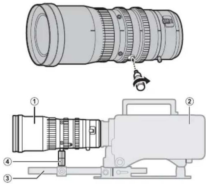
text_image
Technical diagram of a camera lens assembly with numbered parts and labeled parts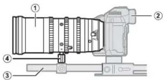
text_image
Technical diagram of a camera with numbered components for identificationtext_image
Diagram of a camera lens mechanism with labeled parts and directional arrows indicating rotation or movement.x 示例

text_image
Technical diagram of a mechanical component with numbered parts and directional arrow indicating motion or movementnatural_image
Simple line drawing of a circular object inside a rounded square frame (no text or symbols)EMK18-55mm
X MKX 18-55 mm
natural_image
Simple geometric diagram with concentric rectangles and a central circle (no text or symbols)EMK50-135mm
X MKX50-135mm
镜头控制
text_image
Technical diagram of a mechanical device with numbered components and directional arrows indicating motion or flow.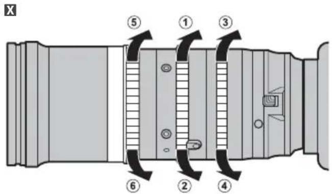
text_image
X ⑤ ① ③ ⑥ ② ④EX 微距变焦
text_image
E ① ③ ② →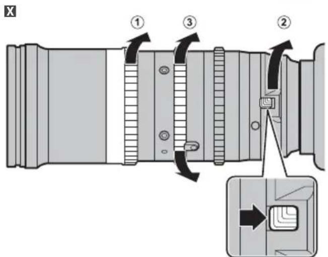
text_image
Technical diagram of a camera lens assembly with numbered parts and directional arrows indicating motion or assembly steps.调整镜后距离
E http://www.fujifilm.com/support/optical_devices/tv_cine/resources/
X http://www.fujifilm.com/support/digital_cameras/compatibility/index.html
维修与保养
E 购买 MK18-55mmT2.9/MK50-135mmT2.9 的用户可参阅以下 URL:
http://www.fujifilm.com/support/optical_devices/tv_cine/pdf/index/Tv_Cine_Lenses_Contact_Us.pdf
X 购买 MKX18-55mmT2.9/MKX50-135mmT2.9 的用户可参阅本产品随附的信息页或以下 URL:
http://www.fujifilm.com/contact/
仕様 /Specifications
The MK 18-55 mmT2.9 and MK 50-135 mmT2.9 have the same external dimensions.
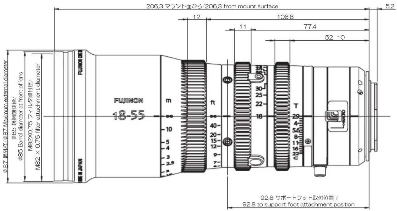
text_image
206.3 マウント面から/206.3 from mount surface 12 106.8 11 77.4 52 10 5.2 φ87 最外径/φ87 Maximum external diameter φ85 簃鋼前側徑/ φ85 Barrel diameter at front of lens M82×0.75 フィルタ取付径/ M82 × 0.75 filter attachment diameter FUJINON 18-55 m ft 40- 20- 15- 12- 9- 7- 2 E J P A N T 29 4 5.6 8 11 16 22 92.8 サポートフット取付位置 / 92.8 to support foot attachment positionThe MKX 18-55 mmT2.9 and MKX 50-135 mmT2.9 have the same external dimensions.
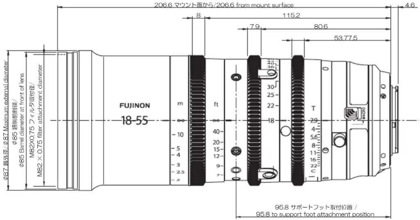
text_image
206.6 マウント面から/206.6 from mount surface 8 115.2 7.9 80.6 53.77.5 4.6 φ87 長外径/φ87 Maximum external diameter φ85 境側前側径/ φ85 Barrel diameter at front of lens M82×0.75 フィルタ取付径/ M82 × 0.75 filter attachment diameter FUJINON 18-55 m ft 40- 20- 15- 12- 9- 7- 18 30 25 22 36 T 2.9 4- 5.6 8- 11- 16- 22- c HA090 95.8 サポートフット取付位置 / 95.8 to support foot attachment positionFUJIFILM Worldwide Network
Purchasers of the MK18-55mmT2.9/MK50-135mmT2.9 are referred to the following URL: http://www.fujifilm.com/support/optical_devices/tv_cine/pdf/index/Tv_Cine_Lenses_Contact_Us.pdf
Purchasers of the MKX18-55mmT2.9/MKX50-135mmT2.9 are referred to the information sheet included with the product or to the following URL:
http://www.fujifilm.com/contact/
FUJIFILM
富士フイルム株式会社