PFDS 120 A2 - Welding machine PARKSIDE - Free user manual and instructions
Find the device manual for free PFDS 120 A2 PARKSIDE in PDF.
| Product Type | Flux-Cored Wire Welder |
| Brand | Parkside |
| Model | PFDS 120 A2 |
| Max Welding Current | 120 A |
| Supply Voltage | 230 V ~ 50 Hz |
| Max Wire Spool | 1 kg |
| Welding Mask Included | Yes |
| Overload Protection | Yes |
| Welding Current Adjustment | Yes, variable |
| Wire Feed Speed | Adjustable |
| Weight | Approximately 8 kg |
| Maintenance and Cleaning | Clean regularly, check cables and connections |
| Safety | Thermal protection, welding screen |
| Warranty | 2 years |
| Compliance | CE, EN 60974-1, EN 60974-10 |
| Usage | Arc welding with flux-cored wire, no gas required |
Frequently Asked Questions - PFDS 120 A2 PARKSIDE
User questions about PFDS 120 A2 PARKSIDE
0 question about this device. Answer the ones you know or ask your own.
Ask a new question about this device
Download the instructions for your Welding machine in PDF format for free! Find your manual PFDS 120 A2 - PARKSIDE and take your electronic device back in hand. On this page are published all the documents necessary for the use of your device. PFDS 120 A2 by PARKSIDE.
USER MANUAL PFDS 120 A2 PARKSIDE
FLUX CORED WIRE WELDER PFDS 120 A2
Introduction
Residual risk
KEEP OUT OF THE REACH OF CHILDREN!
-
Intendeduse
-
Delivery contents
-
Parts description
-
Safety notes
- Technical specifications

Note:
- Danger sources from lightarc welding

ATTENTION!
after a few hours, if sufficient

Danger from welding sparks:
Dangers from arc welding:
Danger from electrical shock:
Danger from electromagnetic fields:
Danger from welding smoke:
Welding-screen-specific safety notes
-
Environments with increased electrical risks
-
Welding in confined spaces
-
Adding up of open-circuit voltages
Use of shoulder slings
-
Protection from radiation and burns
-
Protective clothing
EMC device classification
Before use
Assembly
- Assembling the welding mask
- Inserting the flux-cored wire
A WARNING!
Commissioning
-
Switching the device on and off
-
Setting the welding current
| Voltage (V) | Wire feed | Welding current |
- Setting the wire feed

WARNING!
Overload protection
Welding mask
WARNING! HEALTH HAZARD!
Welding
WARNING!
Please proceed as follows once you have electrically connected the welding device:
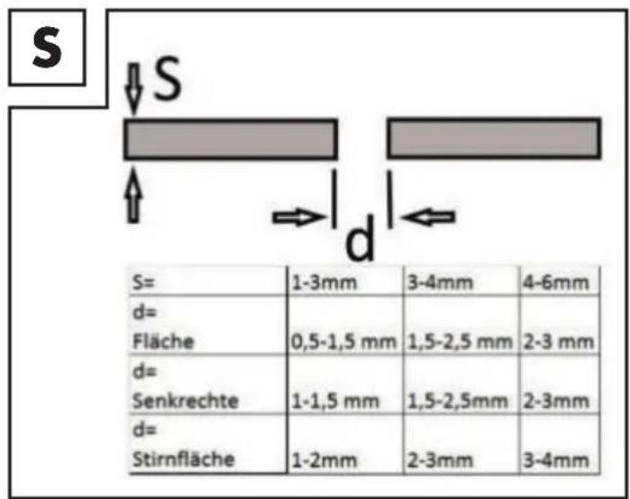
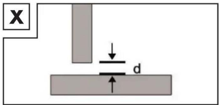
Flat butt welds

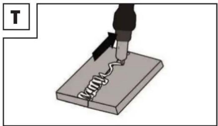
- Creating a weld
Forehand welding
Backhand welding
Welded joints
Butt welds
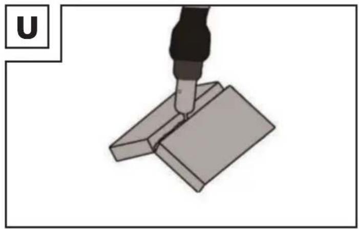
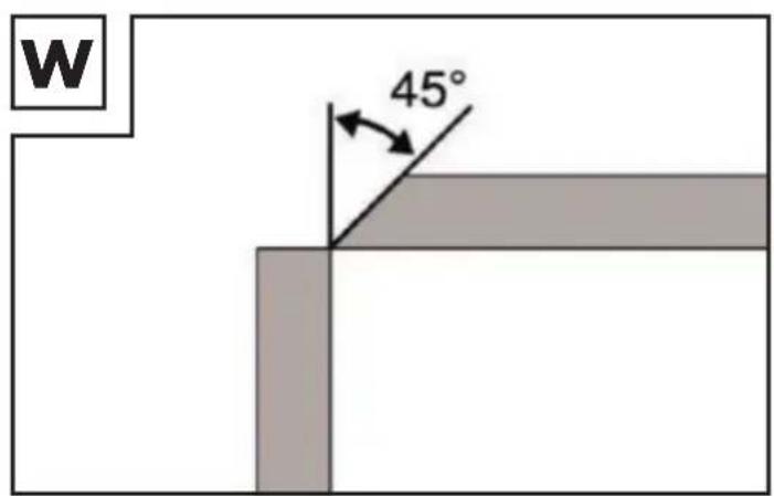
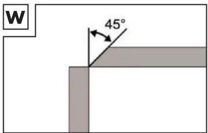
Welds on the outer edge
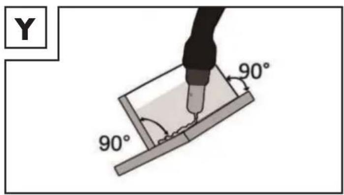
Welds on an inner corner
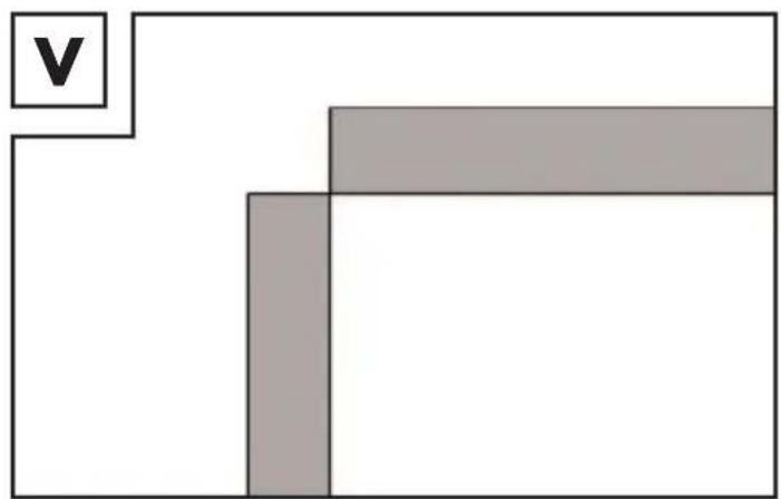

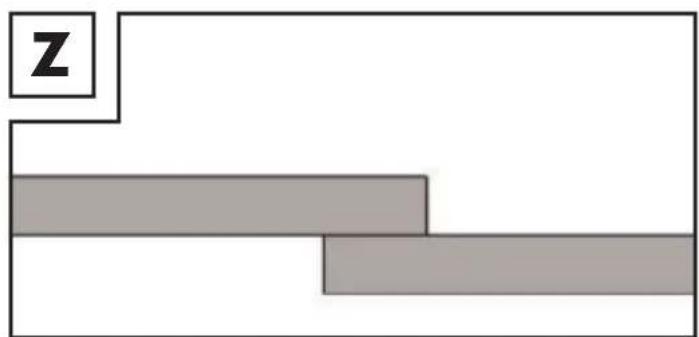
Overlap welds
Fillet weld connections
- Maintenance and cleaning
Flux cored wire welder
EC low-voltage directive
EU directive on electromagnetic compatibility
RoHS directive
Information about recycling and disposal
Don't waste, recycle!


EN 60974-1:2012 EN 60974-10:2014/A1:2015
EU Declaration of Conformity
C.M.G.GmbH Katharina-Loth-Str.15 66386 St. Ingelbert Telefon: +49 6894 9989750 Telefax: +49 6894 9989729
Warranty and service information
Creative Marketing & Consulting GmbH warranty
- Extent of warranty
Warranty conditions
- Processing of warranty claims
Warranty period and statutory warranty claims
Address:
C. M. C. GmbH

Note:

Service
How to contact us:
GB/IE
IAN 345149_2004
RISQUE POUR LA SANTÉ !
Soudage

AVERTISSEMENT
VULDRAAD LASAPPARAAT PFDS 120 A2
- Inleiding
Restrisico
BUITEN HET BEREIK VAN KINDEREN HOUDEN!
WAARSCHUWING RISICO VOOR DE GEZONDHEID!
Overlappende lasverbindingen
Hoeklasverbindingen